

ID 2021 2.0 July 2018
User Manual QT250 and QT800
with Dual CAN and Failsafe options

Table 1: Document history for User Manual QT250 and QT800
Document
ID
Revision
Author
Changes
Approved
by
Date
2021
1.0
SKO
Based on 1372 with
adjustments.
Updated version
with Failsafe option
May 2018
2021
2.0
SKO
Added information
on Dual CAN
July 2018
Copyright © 2018, Eltorque AS
This document is submitted in confidence and contains proprietary information which shall not be
reproduced or transferred to others for the purpose, tender or any other intensions without written
permission of Eltorque AS

User Manual QT250 and QT800, ID 2021 2.0 July 2018
Page 3 of 86
Table of Contents
Chapter 1 Introduction ............................................................................................................................................................... 7
1.1 System Overview ........................................................................................... 7
1.2 Description .................................................................................................... 8
1.3 Features ......................................................................................................... 9
1.4 Area of use .................................................................................................... 9
1.5 Technical support information .................................................................. 10
1.6 Reader groups ............................................................................................. 10
1.7 Notation used in this manual ..................................................................... 10
1.8 Related documentation .............................................................................. 11
1.9 Disclaimer .................................................................................................... 11
1.10 Terms and abbreviations ............................................................................ 11
1.11 About this user manual .............................................................................. 13
Chapter 2 HSE Information.................................................................................................................................................... 15
2.1 Care and cleaning of actuator .................................................................... 15
2.2 Disposal and waste handling ..................................................................... 15
Chapter 3 Product Description ........................................................................................................................................... 17
3.1 QT250 and QT800 actuators ..................................................................... 17
3.2 Actuator control system examples ............................................................ 18
3.3 Technical specification ............................................................................... 19
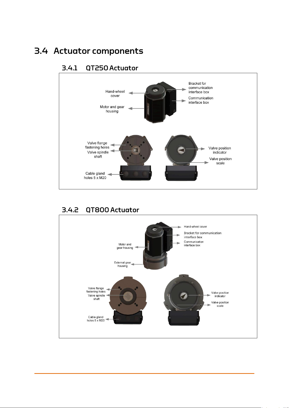
3.4 Actuator components ................................................................................. 21
3.4.1 QT250 Actuator --------------------------------------------------------------------- 21
3.4.2 QT800 Actuator --------------------------------------------------------------------- 21
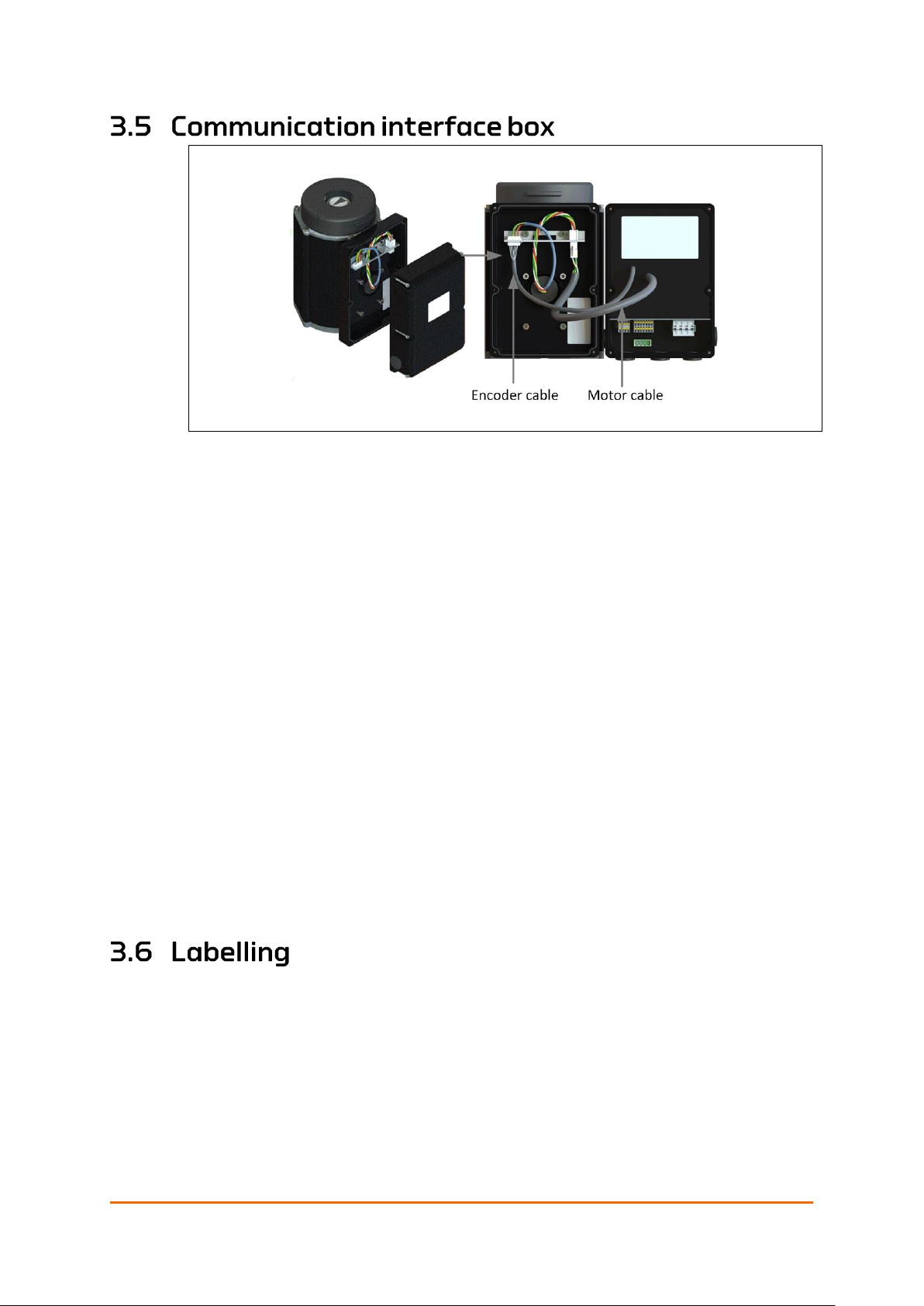
3.5 Communication interface box ................................................................... 22
3.6 Labelling ...................................................................................................... 22
3.7 Cabling ......................................................................................................... 23
3.8 Storage ......................................................................................................... 23
3.9 Engineering information ............................................................................. 24
3.9.1 Power circuit design --------------------------------------------------------------- 24
3.9.2 Duty performance ------------------------------------------------------------------ 24
3.9.3 Endurance ------------------------------------------------------------------------------ 25
3.9.4 Shielding considerations -------------------------------------------------------- 25
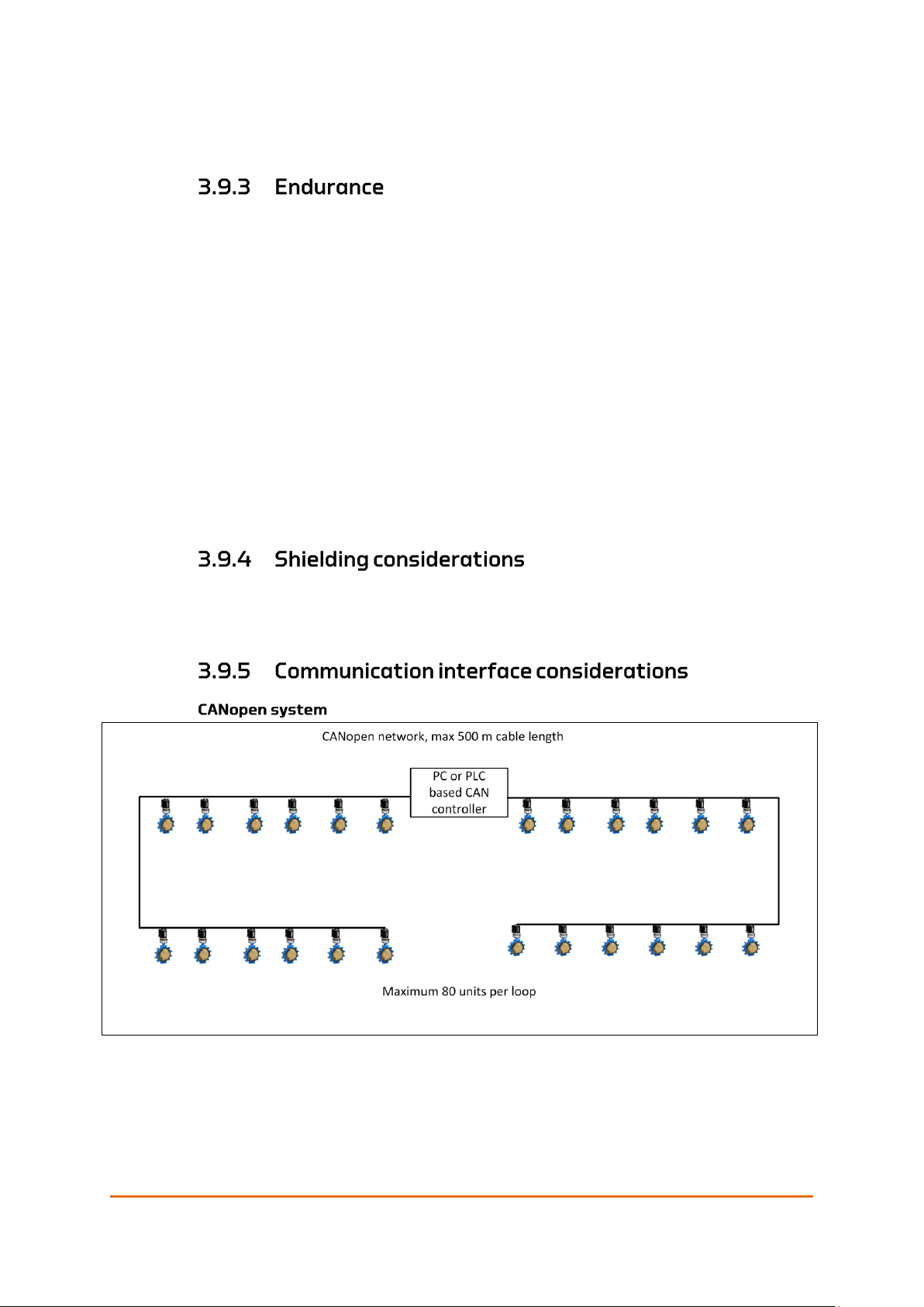
3.9.5 Communication interface considerations ------------------------------- 25
3.9.6 Installations with Eltorque Hybrid Marine Cable --------------------- 27
3.9.7 Orientation ----------------------------------------------------------------------------- 28
3.9.8 Space requirements ---------------------------------------------------------------- 28
3.9.9 Mounting -------------------------------------------------------------------------------- 31
3.9.10 Additional information adaption actuator/valve --------------------- 31
3.9.11 Torque considerations for valve and actuator ------------------------- 31
3.9.12 Closing time --------------------------------------------------------------------------- 31
3.9.13 Configuration ------------------------------------------------------------------------- 32
Chapter 4 Mounting and Installation .............................................................................................................................. 33
4.1 Mounting the actuator on the valve .......................................................... 33
4.2 Mounting procedure QT250 and QT800 ................................................... 33
4.3 Valve flange fastening holes ...................................................................... 34
4.4 Cable connection overview ......................................................................... 35

Table of Contents
Page 4 of 86
User Manual QT250 and QT800, ID 2021 2.0 July 2018
4.5 Cable glands ................................................................................................ 36
4.6 Power supply connection............................................................................ 37
4.7 Grounding (earthing) .................................................................................. 39
4.8 Communication connection interfaces ...................................................... 39
4.8.1 Connection procedure ------------------------------------------------------------ 39
4.8.2 CANopen interface connection ----------------------------------------------- 39
4.8.3 Digital interface connection --------------------------------------------------- 41
4.8.4 Analog interface connections ------------------------------------------------- 42
Chapter 5 Operation .................................................................................................................................................................. 43
5.1 Manual operation ........................................................................................ 43
5.2 Error alarms and error handling ................................................................ 44
5.2.1 GENERAL alarm ---------------------------------------------------------------------- 44
5.2.2 POSITION UNDEFINED alarm --------------------------------------------------- 44
5.2.3 TEMPERATURE alarm -------------------------------------------------------------- 45
5.2.4 TORQUE alarm ------------------------------------------------------------------------ 45
5.3 Troubleshooting .......................................................................................... 46
Chapter 6 Maintenance ............................................................................................................................................................ 49
6.1 Maintenance overview ................................................................................ 49
6.2 Inspection .................................................................................................... 49
6.3 Tightening of bolts ..................................................................................... 49
6.4 Lubrication................................................................................................... 49
6.5 Care and cleaning of anodizing ................................................................. 49
Chapter 7 Technical Details.................................................................................................................................................. 51
7.1 Surface treatment ....................................................................................... 51
7.2 Communication interface ........................................................................... 51
7.2.1 CANopen interface ----------------------------------------------------------------- 51
7.2.2 Digital interface ---------------------------------------------------------------------- 51
7.2.3 Analog interface --------------------------------------------------------------------- 53
Chapter 8 Ordering Information and Recommended Spare Parts ................................................................ 55
Dual CAN Option .................................................................................................................................................. 59
A.1 Terms and abbreviations ............................................................................ 59
A.2 Product description ..................................................................................... 59
A.2.i. Differences from standard to Dual CAN actuator -------------------- 60
A.3 Actuator control system examples ............................................................ 60
A.4 Engineering information ............................................................................. 61
A.4.i. Cabling considerations ----------------------------------------------------------- 61
A.5 Mounting and installation .......................................................................... 61
A.6 Operation ..................................................................................................... 62
A.7 Ordering information .................................................................................. 62
A.8 Technical details ......................................................................................... 63
A.8.i. Dual CAN ------------------------------------------------------------------------------- 63
Failsafe Option ...................................................................................................................................................... 65
B.1 Terms and abbreviations ............................................................................ 66
B.2 Disposal and waste handling ..................................................................... 66
B.3 Product Description .................................................................................... 66
B.3.i. Differences from standard to failsafe actuator ----------------------- 67
B.3.ii. Failsafe actuator components ------------------------------------------------- 67
B.4 Planning ....................................................................................................... 68
B.4.i. Installation plan --------------------------------------------------------------------- 68

Table of Contents
User Manual QT250 and QT800, ID 2021 2.0 July 2018
Page 5 of 86
B.4.ii. Maintenance plan ------------------------------------------------------------------- 68
B.4.iii. Storage ----------------------------------------------------------------------------------- 68
B.4.iv. Battery charge ------------------------------------------------------------------------ 69
B.4.v. Space requirements ---------------------------------------------------------------- 69
B.5 System interface .......................................................................................... 71
B.6 Mounting and installation .......................................................................... 71
B.6.i. Opening the actuator to access connectors ---------------------------- 72
B.7 Operation ..................................................................................................... 72
B.7.i. Operation of the hand-wheel -------------------------------------------------- 72
B.7.ii. Actuator states ----------------------------------------------------------------------- 72
B.7.iii. LED indication ------------------------------------------------------------------------ 73
B.7.iv. Troubleshooting overview ------------------------------------------------------ 74
B.8 Maintenance ................................................................................................ 74
B.8.i. Battery discharge and charge ------------------------------------------------- 74
B.8.ii. Changing battery on the UPS unit ------------------------------------------- 75
B.9 Ordering information .................................................................................. 79
Torque and Screw Recommendations .................................................................................................... 81
C.1 Eltorque torque recommendations ............................................................ 81
C.2 Mounting screws and lubrication .............................................................. 81
C.3 M4 screws on communication interface box ............................................ 82
Earthing Methods in Maritime Installations ....................................................................................... 83

Table of Contents
Page 6 of 86
User Manual QT250 and QT800, ID 2021 2.0 July 2018
This page is left intentionally blank
User Manual QT250 and QT800, ID 2021 2.0 July 2018
Page 7 of 86
The Eltorque Lifelong Intelligent control concept provides maintenance-free,
configurable eco-friendly and fully electric actuators with real-time feedback.
The Eltorque actuators are divided in two main families:
• QT-series of actuators are ideal for quarter-turn valves such as butterfly and
ball-valves.
• MT-series of actuators are multi-turn actuators optimized for linear valves
such as globe valves, and with a form factor that make the MT-series ideal for
manifold actuation.
The Eltorque actuators are fully electric and can be connected in series. They
offer a plug and play solution with low installation costs and high level of
security. By combining the Eltorque actuators with the Eltorque Hybrid Marine
Cable, the cost of installation is even further reduced.
The Electric bus connected actuator installation eliminates the cable clutter,
transportation loss, air or oil leakage associated with conventional actuator
The use of permanent magnet-based motor technology and efficient electric,
mechanics and firmware design guarantee an eco-friendly and cost-efficient
ownership.
Eltorque actuators have a proven track record of lifelong maintenance-free
operation with 15 years of proven operation.
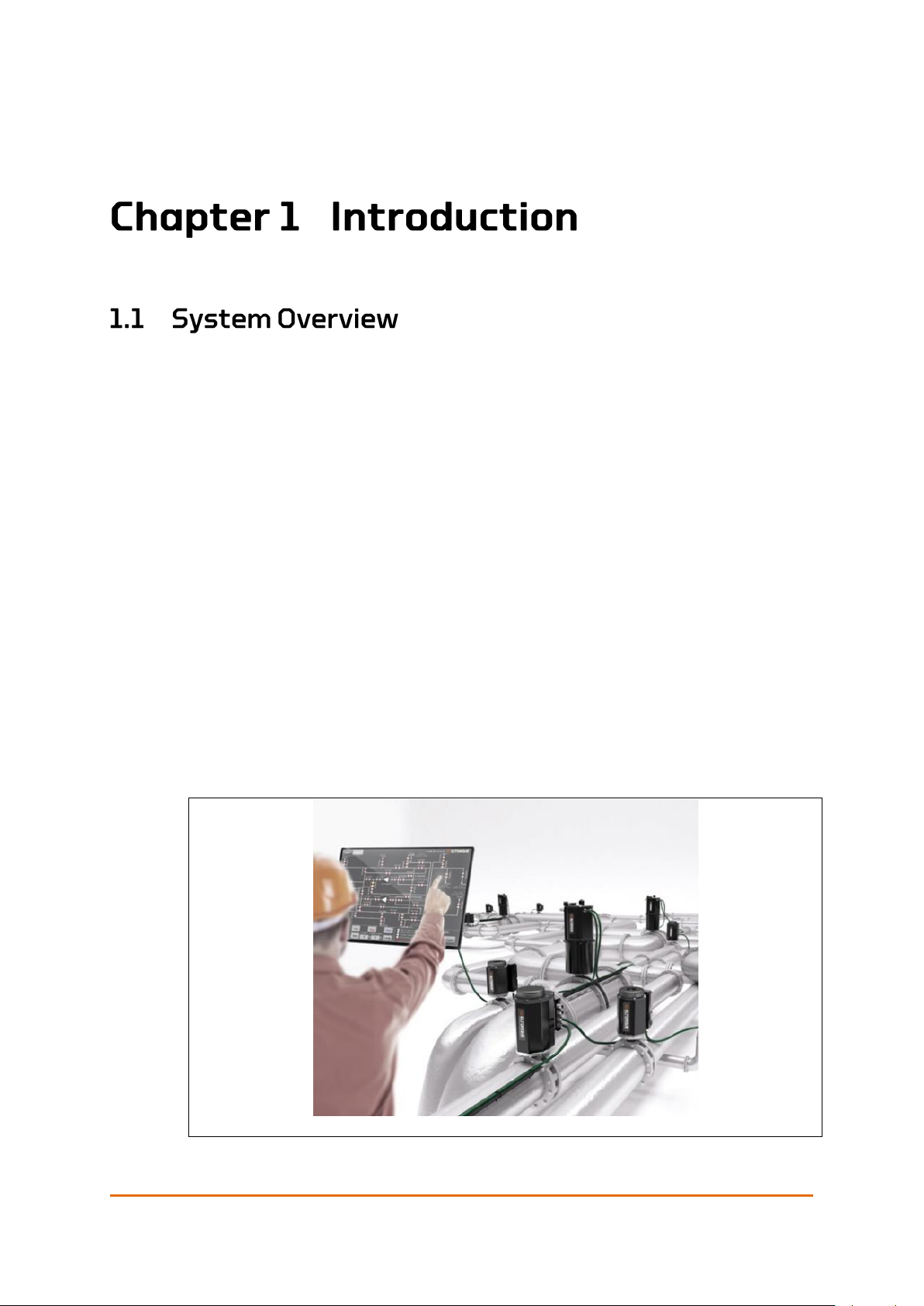
Figure 1: System overview example

Introduction
Page 8 of 86
User Manual QT250 and QT800, ID 2021 2.0 July 2018
The QT250 and QT800 described in this manual are part of the QT series. This
series is characterized by their quarter-turn movement and low energy
consumption along with their small footprint. They are suited for butterfly, ball
and other quarter-turn valves.
The QT250 and QT800 actuators are available in different versions with
corresponding User Manuals:
Table 2: Product overview
A= Plain actuator, B= with Failsafe option, R1= with Dual CAN, R2= with Failsafe
and Dual CAN, H= Actuator with cable glands for Eltorque Hybrid Marine Cable.
Product
Product id
User Manual
QT250 2.5 CANopen Actuator
250.120.5A and 250.120.5AH
Doc ID 2021
QT250 2.5 Digital/Analog Actuator
250.150.5A
QT800 2.5 CANopen Actuator
800.120.5A and 800.120.5AH
QT800 2.5 Digital/Analog Actuator
800.150.5A
QT250 2.5 CANopen Failsafe Actuator
250.120.5B and 250.120.5BH
QT800 2.5 CANopen Failsafe Actuator
800.120.5B and 800.120.5BH
QT250 2.5 Dual CAN Actuator
250.120.5R1 and 250.120.5R1H
QT800 2.5 Dual CAN Actuator
800.120.5R1 and 800.120.5R1H
QT250 2.5 Dual CAN and Failsafe
Actuator
250.120.5R2 and 250.120.5R2H
QT800 2.5 Dual CAN and Failsafe
Actuator
800.120.5R2 and 800.120.5R2H
QT250 1.0 CANopen Actuator
250.120.1and 250.120.1H
Doc ID 1372
QT250 1.0 Digital Actuator
250.110.1
QT250 1.0 Analog Actuator
250.130.1,
QT250 1.0 Modbus Actuator
250.140.1 and 250.140.1H
QT800 1.0 CANopen Actuator
800.120.1and 800.120.1H
QT8001.0 Digital Actuator
800.110.1
QT800 1.0 Analog Actuator
800.130.1
QT800 1.0 Modbus Actuator
800.140.1and 800.140.1H
QT250 1.0 CANopen Actuator - Open
Deck
250.121.1 and 250.121.1H
QT250 1.0 Digital Actuator- Open Deck
250.111.1
QT250 1.0 Analog Actuator- Open Deck
250.131.1
QT250 1.0 Modbus Actuator- Open
Deck
250.141.1 and 250.141.1H
QT800 1.0 CANopen Actuator- Open
Deck
800.121.1 and 800.121.1H
Introduction
User Manual QT250 and QT800, ID 2021 2.0 July 2018
Page 9 of 86
Product
Product id
User Manual
QT800 1.0 Digital Actuator- Open Deck
800.111.1
QT800 1.0 Analog Actuator- Open Deck
800.131.1
QT800 1.0 Modbus Actuator- Open
Deck
800.141.1 and 800.141.1H
QT250 CANopen 2.4 EX Actuator
EX250.125.4 and EX250.125.4H
Doc id 1193
QT800 CANopen 2.4 EX Actuator
EX800.125.4 and EX800125.4H
This User Manual describes the standard 2.5 version with the options for Dual
CAN and Failsafe.
The Eltorque actuators provides a wide range of attractive features:
• Optimized single-axis architecture, ensuring a compact and low-weight
actuator.
• Accurate real-time magnetic position control with no mechanical limit
switches, ensuring maintenance-free operation.
• Few spare parts - low lifetime costs.
• Easy setup and commissioning – low installation cost.
• Specific alarms including over-torque and temperature – providing high
operation safety.
• Robust implementation of CANbus protocol ensuring a reliable bus
connection.
• Reduced power consumption that gives a greener profile.
• Self-lock feature which allows movements from the motor, but immediately
locks movements from the valve side.
• Fast and precise motor that reduces the closing time.
• Low start-up load which enables a high number of actuators per power fuse.
• Remote programming via the CAN bus protocol on the Hybrid Marine Cable.
• Specific alarms including over-torque and temperature – providing high
operation safety.
• Option for Dual CAN see Appendix A on page 59.
• Option for Failsafe operation see 0 on page 64
Eltorque actuators are an ideal choice in a wide range of Maritime and Onshore
systems such as:
• Cargo handling
• Bilge and ballast

Introduction
Page 10 of 86
User Manual QT250 and QT800, ID 2021 2.0 July 2018
• Tank gauging
• SPS system
• Anti-heeling systems
• RSW systems
• Bulk handling
• Fuel systems
• Hydro power and district heating
• Waste water treatment
• HVAC system
• Fire water system
• Oil Production system, oil transfer line
If you require technical support outside of this manual, we recommend that you
use the support functions available on the web-site or contact us via e-mail.
If you have feedback to this manual, that should also be routed through e-mail.
Eltorque AS
Julianus Holms veg 34
7071 Trondheim
Norway
Web: www.eltorque.no
e-mail: info@eltorque.no
Phone: +47 74 85 55 20
Fax: +47 74 85 55 12
The following reader groups have been defined for this User Manual:
• Project and engineering personnel
• Installation personnel
• Operators
• Supervisors
• Technical support personnel
• Technical management personnel
The following notations have been used in this manual:
Bold is used for commands and menu selection.
Italic is used to give emphasis to information. It is also used for names of
documents referred to in the manual.
Note! Note is used to draw attention to important or helpful information
Caution! A caution is used when there is a danger that the equipment is damaged
if you do not follow the instructions.

Introduction
User Manual QT250 and QT800, ID 2021 2.0 July 2018
Page 11 of 86
Warning is used to draw attention to information of very high importance,
for example to avoid injuries to personnel.
This User Manual QT250 and QT8001 is related to the following documentation:
Table 3: Related documentation
Document
Document ID
Hybrid Marine Cable product datasheet
Eltorque document ID 1946
Eltorque E3C Manual
Eltorque document ID 1687
Guidelines for earthing in maritime
installations
Published by the Norwegian Electrical
Safety Directorate. Available on net or
supplied by Eltorque on request.
System Integrators Manual CANopen
Interface
Eltorque document ID 1691
User Manual
QT250 2.4 EX
QT800 2.4 EX
Eltorque document ID 1193
User Manual QT250 and QT800
1
Eltorque document ID 1372
Note! 1 See Table 2: Product overview on page 8 for specification of the relevant User
Manuals for the QT250/QT800 series.
The information contained in this document is subject to change without prior
notice. Eltorque AS shall not be liable for errors contained herein or for incidental
or consequential damages about the furnishing, performance, or use of this
document. It is the customer’s responsibility to verify that he has the latest
revision available by checking the document area of www.eltorque.no
Table 4: Terms and abbreviations
Term
Description
ABS
American Bureau of Shipping.
AFD
Asbestos Free Declaration.
Analog Control
Step-less control utilizing analog signals, e.g. 4-20 mA. Allows positioning of the
valve actuator between Open and Closed.
BTO
Break to open. The torque required to unseat the closed valve.

Introduction
Page 12 of 86
User Manual QT250 and QT800, ID 2021 2.0 July 2018
Term
Description
CAN/CAN bus
Controller Area Network.
CAN bus is a fieldbus which allows communication between a maximum of 127
actuators connected to the same network. It is not a “master-slave” network (ref.
Modbus), hence all the nodes in the network can actively send messages at their
own initiative. Communication is prioritized meaning that urgent messages are
transmitted and received before information with lower priority. Compared to
Modbus, CAN bus has quite a few advantages:
− More reliable communication
− More nodes per network
− More control and configuration features are available
− Higher performance
CANopen
CANopen is a higher-level protocol and is running on top of the CAN protocol for
all Eltorque actuators.
The standard consists of an addressing scheme for the nodes on the CAN bus
and several small protocols for communicating with each node. In terms of the
OSI model, CANopen implements the levels above, including the network layer.
CCS
Central Control System.
Communication
Interface Box
Electronic device controlling the actuator according to signals from an overall
control system such as a PLC or other type of electronic controller.
Configuration
The set-up of parameters, which affects the actuator’s performance and
behavior.
Digital Control
Simple control utilizing relays, on/ off switches and indicators. Allows only Open
or Closed functionality for a valve actuator.
DNV GL
Det Norske Veritas Germanischer Lloyd.
E3C
Eltorque Common Configuration Controller.
E-VCI
Eltorque Valve Control Interface
E-VCS
Eltorque Valve Control System offers a dedicated control system
for operation of Eltorque actuators.
Eltorque Valve Control System is suitable for installations where the operator
requires full control of all valves and pumps, and in addition monitor level,
temperature, flow and pressure.
Hazardous area
Area in which the permanent or periodical presence of explosive substances
causes a risk of explosion.
Products described in this manual are not suitable for use in hazardous areas.
Eltorque can deliver actuators for use in such areas if required. Please contact
your local representative for further details.
HMI
Human Machine Interface.
HSE
Health, Safety and Environment.
HVAC
Heath, ventilation and air condition
IACS
International Association of Classification Societies
IAS
Integrated Automation System.
ICS
Integrated Control System.
IMO
International Maritime Organization
LR
Lloyd’s Register.
MAST
Maximum allowable stem torque/thrust.
MD
Material Declaration.
MEPC
The Marine Environment Protection Committee

Introduction
User Manual QT250 and QT800, ID 2021 2.0 July 2018
Page 13 of 86
Term
Description
OSI model
Open Systems Interconnection model. The model is a conceptual model that
standardizes communication systems without regard to the underlying internal
structure. The model partitions a communication system into abstraction layers.
Out of range
Definition of position. The outgoing shaft is outside the defined position area.
PF
Power factor
PCB
Printed circuit board.
PLC
A Programmable Logic Controller is a digital computer used for automation of
industrial processes, such as control of machinery on factory assembly lines,
measurement and control of process plants etc.
RSW
Refridgerated sea water system
SDoC
Supplier Declaration of Conformity.
SOLAS
Safety Of Life At Sea – conversion under IMO concerning safety for personnel and ships at
sea.
SPC
Statistical process control
VA
Voltampere
UPS
Uninterruptable power supply.
Valve
A valve is a device that controls the flow of materials (gases, fluidized solids,
slurries, or liquids) by opening, closing, or partially obstructing various
passageways.
Actuator
A device for control of valves in various process control systems.
Valve top
flange
The flange on top of the valve which integrates the actuator. Key parameters to
be aware of are summarized in 3.3 Technical specification on page 19. As an
example, butterfly valves typically comprise four screw holes for the flange
integration and a square stem for valve operation.
Within range
Definition of position. The outgoing shaft is within the defined position area.
This user manual describes the guidelines for installation, setup and operation of
QT250 and QT800 in a valve control system. The valid products for this manual
are listed in Table 2: Product overview on page 8.
Chapter 1 introduces the product and this manual.
This chapter is intended for all reader groups.
Chapter 2 informs on health, safety and environment issues.
The reader group for this chapter is for supervisors, technical support and
technical management personnel.
Chapter 3 gives a product description including the mechanical construction of
the actuator, technical specifications and a functional description. There is also
an overview of technical issues that should be considered in the design and
planning phase for the installation.
The reader group for this chapter is supervisors, project and planning personnel.

Introduction
Page 14 of 86
User Manual QT250 and QT800, ID 2021 2.0 July 2018
Chapter 4 covers the mechanical installation on valves and the electrical
installation of power and control signal.
The reader group for this chapter is installation personnel.
Chapter 5 covers the use of the actuator such as how to use the manual
emergency operation. There is also an overview of error messages and a
troubleshooting overview.
The reader group for this chapter is operators.
Chapter 6 covers maintenance, inspection and repair of the actuator.
The reader group for this chapter is operators, technical support and
management personnel.
Chapter 7 gives more in-depth technical information on the product.
The reader group for this chapter is technical support and management
personnel.
Chapter 8 gives ordering information.
The reader group for this chapter is technical support and management
personnel.
Appendix A describes the Dual CAN option, how to install and operate an
actuator with this option. The reader group for this chapter is installation
personnel, operators, support personnel and management personnel.
Appendix B describes the Failsafe option, how to install and operate an actuator
with this option. The reader group for this chapter is installation personnel,
operators, support personnel and management personnel.
Appendix C gives an overview of torque recommendations for actuator bolts.
The reader group for this chapter is installation personnel.
Appendix D includes the document “Earthing Methodology in Maritime
Installations” The reader group for this chapter is installation personnel,
technical support and technical management personnel.

User Manual QT250 and QT800, ID 2021 2.0 July 2018
Page 15 of 86
This chapter includes safety information that the user needs to know to operate
the equipment without doing harm to personnel or the environment.
The operation of the equipment is safe provided that the recommended
operating procedures are followed. There are specific hazards however
that need to be addressed so that the user knows how to deal with them.
Electrical installations shall be designed and installed by personnel with
certifications according to applicable laws and regulations. Ensure that all
such work is done according to applicable laws and regulations.
Service must always be performed by trained personnel.
All batteries and electronic equipment may contain substances harmful to the
environment. After removing used equipment, return them for disposal
according to local governmental guidelines.
Caution! Do not use ammonia, alkaline cleaners, lye or strong acid for cleaning as
this can damage the protective anodized layer of the product surface.
Caution! Do not use high pressure power washer directly on the actuators as the
product is not IP69K rated.

HSE Information
Page 16 of 86
User Manual QT250 and QT800, ID 2021 2.0 July 2018
This page is left intentionally blank
User Manual QT250 and QT800, ID 2021 2.0 July 2018
Page 17 of 86
The QT250 and QT800 are the most sold products in the Eltorque portfolio. They
have been used on a various of vessel types on butterfly and ball valves. The
QT800 is based on the QT250, with an additional gearbox to further increase the
output torque. They are equipped with a magnetic position sensor that gives a
correct position feedback, even after a power outage. Both can be manually
operated by the means of a fixed hand wheel located under the cover on top of
the actuator without the need for external tools. Both QT250 and QT800 can be
delivered with the Failsafe option described in 0 on page 64 and the CAN Dual
option described in Appendix A on page 59.
The QT250 actuator is suitable for valves with torque requirements between 100250 Nm, while the QT800 is suitable for 320-800 Nm. Both can be delivered with
CANopen, Analog and Digital communication.
Note! For actuators equipped with Failsafe and/or Dual CAN options, these are only
available with the CANopen communication interface.
The actuators are designed to be operational during a temporary submerged
situation, see details for housing in Table 5: System performance parameters for
QT250 and QT800 actuators on page 19.
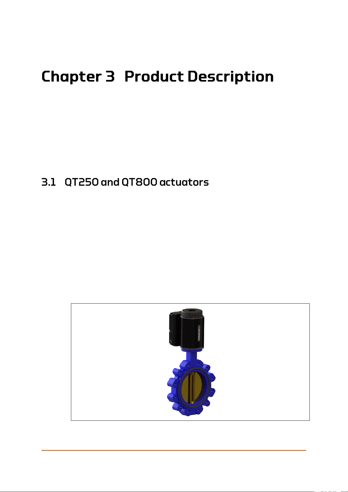
Figure 2: Actuator mounted on a valve
Caution! Remember to have the actuator checked by Eltorque after all submerged
situations to keep the warranty.

Product Description
Page 18 of 86
User Manual QT250 and QT800, ID 2021 2.0 July 2018
The actuator must be integrated with the main control system in one of two
ways:
• Directly to the main control system. In this case it is important to consider
the communication protocol.
• Through a stand-alone sub-system delivered by Eltorque. This is a
standardized hardware and software platform tailored for Eltorque actuators.
The solutions illustrated below show a bus connection with the Eltorque Hybrid
Marine Cable. This cable can be used with the CANopen and Dual CAN
communication interface. In addition, Eltorque actuators support Digital and
Analog connections.
Figure 3 below shows Eltorque actuators that are connected to a cabinet with
Eltorque valve control system (E-VCS). In this example, pump starters are also
connected to the E-VCS. Other equipment, such as sensors can also be connected
to the E-VCS. The E-VCS includes an HMI interface on the cabinet and can also
support an HMI interface on main control level.
Figure 3: Eltorque Valve Control System (E-VCS) with valve and pump control
Figure 4 below shows Eltorque actuators that are connected directly to a
customer specific PLC, PC or other control unit. In addition, Eltorque actuators
support digital and analog connections. On system level, the PLC, PC or
Controller must be compliant with Eltorque communication protocol according to
Eltorque System Integrators Manual.

Product Description
User Manual QT250 and QT800, ID 2021 2.0 July 2018
Page 19 of 86
Figure 4: Eltorque actuator loop connected to Integrated Automation Control System (IAS
or ICS)
Table 5: System performance parameters for QT250 and QT800 actuators
QT250
QT800
Valve flange and max
allowed rated torque
options
100, 150 or 250 Nm
320, 480 or 800 Nm
Closing time options
0-90 movement:
12, 15, or 20 seconds
0-90 movement:
42, 52.5 or 70 seconds
Valve spindle adaptor
SQ17
depth 38 mm/1.50 in
SQ27
depth 45 mm/1.77 in
Max. allowed valve
flange and related
torque
(Ref. ISO5211) 2001E
F05
F07
F10
F10
F12
125
250
500
500
1000
Valve applications
Quarter-turn
Examples:
Butterfly DN50-DN200 PN16
Floating Ball DN65-DN100 CL150
Quarter-turn
Example:
Butterfly DN150-DN200 CL150
Weight
11 kg/24.3 lb
20 kg/44.1 lb
Dimensions (HxWxD)
229 x 156 x 209 mm
9.02 x 6.14 x 8.23 in
333 x 200 x 239 mm
13.11 x 7.87 x 9.41 in
Manual operation –
number of turns
21 turns on hand wheel =
90 movement on valve
73 turns on hand wheel =
90 movement on valve
Color
Black
Housing
IP66 and IP x8 (10 m – 100 hours/32 ft 9.7 in – 100 hours).
Corrosion protected aluminum and steel enclosure.
Should not be exposed to corrosive chemicals.
Storage temperature
5 – 35C/41 – 95F

Product Description
Page 20 of 86
User Manual QT250 and QT800, ID 2021 2.0 July 2018
QT250
QT800
Operating temperature
With Failsafe option
-25 to 55C/-13 to 131F
0 to 45C/32 to 113F
Temperature protection
Motor current is switched off in case of over-heating.
Power supply
1-phase,110 – 240V AC, 50/60 Hz, Max 240 VA
Power consumption
Opening and closing
with max torque1
100 VA, PF 0.79
Power consumption
Standby1
9 VA, PF 0.37
Duty performance
According to AN 15714-
1 / IEC 60034-1
Class A – 10 cycles per hour/52 – 15 min.
Endurance
According to EN 157122
Classes A and B – 10 000 cycles per lifetime.
Cable glands
Up to five M20 glands allows bus connection of power supply and
signal wiring. Use IP68 (10 m 72 hours) cable glands for all wires.
Communication
Interfaces options
CANopen allows positioning and other extended control of the
actuator. The absolute maximum theoretical number of devices allowed
on the bus is 127, but the actual number of nodes is limited by the
baud-rate and the cable quality. Eltorque recommends a maximum of
80 nodes on 500 m/1660ft cable.
Digital 2 DI (Open-Close) and 3 D0 (Open-Close-Alarm.)
Analog Al (Set position) A0 (Feedback position) and D0 (Alarm) (4-20
mA) AI/A0 signal.
Position sensor
Resolution: 360°/12bit = 0.35156°/bit
Integral Non-Linearity (INL): typ. ± 0.8°
Differential Non-Linearity (DNL): ± 0.176°
Output shaft accuracy: 1%
Position feedback not corrupted by power outage.
Configuration
USB connection to PC with Eltorque E3C. Special configuration cable is
needed, see E3C User Manual.
Configurable parameters
Open and Closed positions. Actuator speed, torque and valve position
regions. Inverted IO or bus parameters depending on the applied
communication interface.
Manual operation
Standard feature using fixed hand-wheel. Mechanical valve position
indicator. No need for external tools.
Cover of handwheel
Can be removed and refitted without tools. Protects mechanism against
mechanical damage and foreign objects. The actuator must not be
lifted by the top cover.
Self-lock
The QT250 and QT800 are equipped with a mechanical self-locking
device that locks the valve to the target position when the actuator
movement command is completed.
Certification/type
approval
All valid certificates are listed on www.eltorque.no – support – technical
support – certificates.
1 Earlier versions of the QT250 and QT800 have other values for power consumption, see Table 2:
Product overview on page 8 for information on the correct documentation to consult.
Product Description
User Manual QT250 and QT800, ID 2021 2.0 July 2018
Page 21 of 86
Bottom view
Bottom view Top view
Figure 5: QT250 external construction
Bottom view Top view
Figure 6: QT800 external construction
Product Description
Page 22 of 86
User Manual QT250 and QT800, ID 2021 2.0 July 2018
Figure 7: Communication interface box – CANopen
The communication interface box provides connectors for power, control signals
and configuration media.
The interface box is by default delivered in three versions:
• CANopen – interface using the CAN (Controller Area Network)
communications standard. Eltorque recommends a maximum of 80 nodes
on 500 m/1660 ft. cable.
The actuator can also be delivered with Dual CAN. Standard CANopen is
described in the main parts of this User Manual while Dual CAN is described
in Appendix A on page 59 and onwards.
• Digital – interface allowing simple Open and Close operation of valves.
Actuators with Digital Interface can be controlled directly from a
conventional panel with buttons/switches and indicator lamps. Alternatively,
it can be controlled from a PLC with digital inputs and outputs.
• Analog – interface allowing regulating valves where positioning of the valve
is needed. The actuator provides continuous feedback of its actual position,
for comparison between desired and actual position. Both positioning and
feedback signals are analog 4-20 mA. The Analog Interface also has a digital
Alarm output, which is trigged by failures in both actuator and valve.
If a Modbus interface is required, please contact your Eltorque representative.
More technical details on the different communication interfaces is given in
Chapter 7 Technical Details on page 51.
The label on the actuator housing states the type of communication interface
used in the unit as well as the specifications for torque, temperature, power
supply and IP rating.
The production serial number and the production date are also included.
When the communication interface box has been removed you can see labels
with interface details.

Product Description
User Manual QT250 and QT800, ID 2021 2.0 July 2018
Page 23 of 86
Figure 8: Actuator labels
The cabling specifications depend on the type of communication interface to be
used.
The QT250 and QT800 control box has five threaded M20 holes for cable glands.
When ordering it is important to consider factors like cable type and size, as the
cable glands have a limited cable entry range. Eltorque standard cable glands can
accommodate a cable between 8-14 mm/0.32 – 0.55 in.
To maintain the Eltorque actuator’s IP encapsulation, it is important to use the
correct rated cable glands, see Table 5 on page 19 and chapter 4.5 on page 36.
The actuators have an EMC class A approval according to DNVGL– CG-0339
without the use of EMC glands. They are therefore by default delivered with nonEMC glands. If you require EMC glands, please notify your sales contact when
ordering.
The default glands for the different communication interface boxes and ordering
information is given in Chapter 8.
If your actuator cannot be installed immediately, it must be stored it in a dry
place until you are ready to install and connect cables. The actuator does not
come prepared for long time outdoors storage when arriving from Eltorque.
Details on storage temperature is found in Table 5: System performance
parameters for QT250 and QT800 actuators on page 19.
If the actuator can be mechanically installed, but not cabled, please ensure that
all glands and gland holes are thoroughly tightened to avoid ingress of moist.
The actuator’s IP rating is not valid until correctly installed.
Eltorque cannot accept responsibility for deterioration caused on site if the
actuator has been opened in ways not described as required in this manual. In
principle, the product should be powered within three years after production to
prevent components from derating. All actuators are thoroughly tested before
shipping to give trouble-free operation, if installed and commissioned properly.

Product Description
Page 24 of 86
User Manual QT250 and QT800, ID 2021 2.0 July 2018
Electrical installations shall be designed and installed by personnel with
certifications according to applicable laws and regulations. Ensure that all
such work is done according to applicable laws and regulations.
It important to consider the number of actuators in both the power loop and the
signal loop when using bus-based communication. The loop list should be
finalized and approved before installation of the cable is started.
In case of power loss, none of the actuators in that power loop can be remotely
operated. In case of a signal loss, none of the actuators on that signal loop can
be remotely operated. Manual operation is however possible in both scenarios.
With the Dual CAN and the Failsafe options the system security in case of a
power or signal loss is largely enhanced. More details are found in Appendix A
Dual CAN Option on page 59 and in Appendix B Failsafe Option on page 65.
The power consumption varies depending on whether the actuator is in standby
mode or is running, see Table 5: System performance parameters for QT250 and
QT800 actuators on page 19.
Eltorque actuators may be used according to IEC 60034-1 duty type S2
Industrial Valves – Actuators, chapter 4.7:
For class A - ON/OFF operation, duty performance is defined as the minimum
number of cycles per hour, where "one cycle consists of nominal 90° angular
travel in both directions (i.e. 90° to open + 90° to close), based on an average
load of at least 30 % of the rated torque with the ability to transmit 100 % of the
rated torque for at least 5 % at each end of travel, with a cumulative operating
time not exceeding 15 minutes in one hour." (EN 15714-2, chapter 4.7.2.2, a.).
For class B - inching/positioning, duty performance is defined as the minimum
number of starts per hour, where "one start consists of a movement of at least 1°
in either direction, with a load of at least 30 % of the rated torque. The cyclic
duration factor (i.e. the ratio between the running period and total period)
shall be not less than 25 % (e.g. 1 s. running and 3 s. resting)" (EN 15714-2,
chapter 4.7.2.2, b.)
For classes C and D - modulating and continuous modulating, duty performance
is defined as the minimum number of starts per hour, where "one start consists
of a movement of at least 1°. in either direction, with a load of at least 30 % of
the rated torque" (EN 15714-2, chapter 4.7.2.2, c.).
Rotating electrical machines, chapter 4.2:
Duty type S2: "Operation at constant load for a given time, less than that
required to reach thermal equilibrium, followed by a time de-energized and at
Product Description
User Manual QT250 and QT800, ID 2021 2.0 July 2018
Page 25 of 86
rest of sufficient duration to re-establish machine temperatures within 2 K of the
coolant temperature." (IEC 60034-1, chapter 4.2.2)
Eltorque actuators may be used classes A and B – 10 000 cycles per lifetime.
Endurance is defined according to EN 15714-2, chapter 4.1 and Annex A.
For classes A and B - ON/OFF operation and inching/positioning, endurance
defines the minimum number of cycles to be endured per life time, where "one
cycle consists of nominal 90°. angular travel in both directions (i.e. 90° to open +
90° to close), based on an average load of at least 30 % of the rated torque with
the ability to transmit 100 % of the rated torque for at least 5 % at each end of
travel, with a cumulative operating time not exceeding 15 minutes in one hour."
(EN 15714-2, chapter 4.1.2, b.)
For class B - inching/positioning, duty performance is defined as the minimum
number of starts per hour, where "one start consists of a movement of at least 1°
in either direction, with a load of at least 30 % of the rated torque.
The cyclic duration factor (i.e. the ratio between the running period and total
period) shall be not less than 25 % (e.g. 1 sec running and 3 sec resting)" (EN
15714-2, chapter 4.7.2.2, b.)
Shielded cables and appropriate cable glands should be used if the actuator is
installed near to or connected in the same network as equipment emitting high
levels of disturbances.
Figure 9: CANopen bus network
Note! Eltorque recommends a maximum of 80 nodes on 500 m/1660 ft cable.
Note! The cable between the nodes can be maximum 500m with bus speed with the
Eltorque Hybrid Marine Cable. For other data rates and cable lengths check with
Eltorque service department.

Product Description
Page 26 of 86
User Manual QT250 and QT800, ID 2021 2.0 July 2018
Table 6: Cable requirements and recommendations for CANopen system
Cable parameter
Cable requirements and recommendations
Number of conductors
1 (GND) + twisted pair for CAN_H and CAN_L signals
Length related
resistance / Cross
section
Length related resistance;
typical 70 mΩ/m Max 100 m/m
70 mΩ/ 3ft 3.37 in Max 100 m/3ft 3.37 in
Normally equivalent to 0.5–1.5 mm2/0.02 – 0.06 in2
Cable length (affects
communication speed)
Maximum 500 m/1650 ft.
Shield
EMC glands are not mandatory but is recommended in case
the actuator is placed in conjunction with equipment
emitting high levels of disturbances.
Termination resistor
Nominal 120 Ω Both ends of the signal loop must have the
correct impedance. Use the internal resistor by setting the
terminal jumper in position ON, see Figure 26: CANopen
connection interface terminals on page 40.
For the analog interface, both the input and the outputs are passive. Analog has
two outputs. One Alarm output and one Position output (4 to 20 mA) (see Table
7 for details).
Table 7: Relay outputs – analog interfaces
Function
Value
Rated voltage
24 VAC/VDC
Max. switching voltage
24 VAC/VDC
Rated current
1A
Limiting continuous current
1A
Breaking capacity
Max. 48 VA (1A)
For the digital interface, the digital outputs are passive, and the digital inputs are
active with a 5 V/20 mA rating. The digital output must be powered (see Table 8
for details).
Table 8: Relay outputs – digital interfaces
Function
Value
Rated voltage
48V AC/VDC
Max. switching voltage
48V AC/VDC
Rated current
1A
Limiting continuous current
1A
Breaking capacity
Max. 48 VA (1A)

Product Description
User Manual QT250 and QT800, ID 2021 2.0 July 2018
Page 27 of 86
Table 9: Cable requirements and recommendations digital and analog systems
Cable parameter
Required/ Recommended
Number of conductors
6 recommended twisted pair.
Cross section
0.5 - 1.5 mm2/0.0197 – 0.0591 in2.
Shield
Not mandatory but is recommended in case the
actuator is placed in conjunction with equipment
emitting high levels of disturbances.
Bus connection of actuators is undoubtedly the most cost-effective installation
methodology. Eltorque has developed a ground-breaking Hybrid CANbus/Power
cable especially designed for maritime applications.
Figure 10: Bus connection of actuators
The Eltorque Hybrid Marine Cable combines signal and power cable in a hybrid
cable with maritime type approval. The cable can only be used for installations
with CANopen communication interface box. When this cable is used, only two
cable glands are required, see Chapter 8 Ordering Information and
Recommended Spare Parts.
Figure 11: Hybrid Marine Cable
Further description of the Hybrid Marine Cable is found in the Hybrid Marine
Cable datasheet, Eltorque document ID 1982. The datasheet is available on
www.eltorque.no – Products – System components.
With traditional cabling, four cable glands are required to accommodate both
power and signal cables. When ordering please inform if you intend to use the
Hybrid Marine cable or a standard cable.

Product Description
Page 28 of 86
User Manual QT250 and QT800, ID 2021 2.0 July 2018
The actuator can freely be mounted both vertically standing or horizontally lying
to the side. An upside-down hanging position should be avoided.
Figure 12: QT250 dimensions
Figure 13: QT800 dimensions
During planning, please ensure sufficient space above and around the actuator
for installation, service and manual operation.

Product Description
User Manual QT250 and QT800, ID 2021 2.0 July 2018
Page 29 of 86
There must be a minimum of 150 mm/5.9 in space above and to the sides of the
actuator to accommodate room for installation, operation and service. In front of
the communication interface box there should be at least 200 mm/7.9 in.
Figure 14: QT250 Space requirements for installation, service and manual operation -
side view
Figure 15: QT250 Space requirements for installation, service and manual operation – top
view

Product Description
Page 30 of 86
User Manual QT250 and QT800, ID 2021 2.0 July 2018
Figure 16: QT800 Space requirements for installation, service and manual operation –
side view
Figure 17: QT800 Space requirements for installation, service and manual operation – top
view

Product Description
User Manual QT250 and QT800, ID 2021 2.0 July 2018
Page 31 of 86
The actuators provide fastening holes of different dimension to facilitate
mounting on different types of valves, see details in Figure 20 on page 34 and
Figure 21 on page 35.
When the actuator and the valve do not have a natural match, it is necessary to
use an adaptor. There are various adaptors available, but the two most common
ones are the square reducer and the flange + stem adapter. When buying
actuator and valves together from Eltorque, this is handled by our project
personnel. If you order just the actuator take care to verify the critical
dimensions and whether the valve has parallel or standard configuration. Square
reducers might be necessary. Always use two pieces with QT250. The QT800
only has room for one. The type of reducer to be used depends on the valve type,
please contact your Eltorque representative or Eltorque support for further
details.
Figure 18: QT250 and QT800 Settings for closed position.
The setting for closed position can be changed by using E3C, see Eltorque E3C
Manual.
The actuator must have sufficient torque to operate the valve in all situations
with an acceptable safety margin. Valve type, temperature, operating pressure,
medium density and viscosity and the medium’s effect on the valve friction are
among the variables that need to be evaluated. A change in any of these
variables may change the required operating torque. Preferable a torque table
with all parameters should be used, but for an electrical actuator, the output
torque is constant, reducing the considerations to be made. Using the break to
open (BTO) value usually gives a correctly sized actuator. The break to open
torque is defined as the torque required to move the valve out of the seat.
Be aware that the MAST of the valve needs to be verified to prevent damage to
the stem. Eltorque can assist with the necessary experience in selecting the
correct actuator size for the valve.
For the QT250 and QT800, the closing time is configurable within a predesigned
interval. The opening and closing profiles are shown in Table 5: System
performance parameters for QT250 and QT800 actuators on page 19.

Product Description
Page 32 of 86
User Manual QT250 and QT800, ID 2021 2.0 July 2018
The actuator is configured from a computer and it is delivered with the
configuration specified by the customer. Eltorque provides the E3C
configuration software which runs on a standard PC and the corresponding User
Manual E3C Software.
The software can be downloaded from the Eltorque website www.eltorque.no –
Technical Support – Software.
The Eltorque Configuration Cable is needed to connect the actuator to the
configuration PC/PLC. It must be ordered separately, see Chapter 8 Ordering
Information and Recommended Spare Parts on page 55.
User Manual QT250 and QT800, ID 2021 2.0 July 2018
Page 33 of 86
Keep hands away from the valve flanges
1. Apply multi-purpose corrosion protection grease on the valve spindle to ease
mounting and avoid corrosion.
2. Make sure that the valve and actuator are placed in the same position (closed).
3. Lift the actuator onto the valve; align its valve adapter with the valve spindle
and lower the actuator onto the valve flange.
4. Ensure that the spindle and valve mounting holes fit directly to the actuator.
5. In cases where square reducers are needed always insert two pieces with
QT250. The QT800 only has room for one.
6. Check that the actuator is correctly positioned on the valve. The actuator’s
interface box should be placed in the same direction as the piping direction,
see Figure 19.
If square reducers are needed, se chapter 3.9.10 Additional information
adaption actuator/valve on page 31.
7. Remove the top cover and use the hand wheel to turn the actuator and align
the fastening holes of the valve flanges, see chapter 5.1Manual operation.
8. Insert the fastening screws and use washers according to specifications. For
screw dimensions see Figure 20 and Figure 21.
Tighten fastening screws to the specified torque, see Table 22: Screw torque on
page 81.
Caution! Do not lift the actuator by the top cover.
Mounting and Installation
Page 34 of 86
User Manual QT250 and QT800, ID 2021 2.0 July 2018
Figure 19: Piping direction
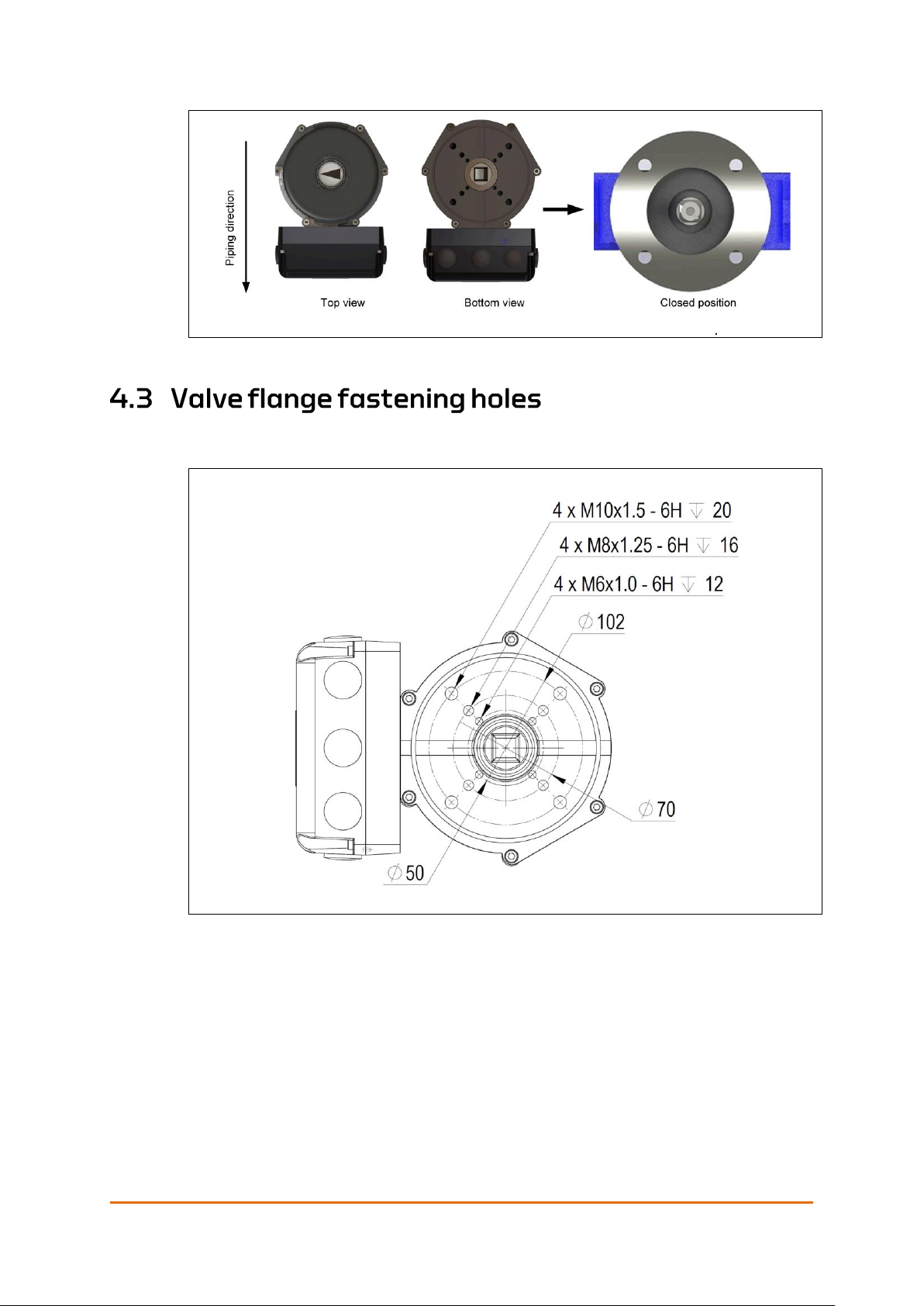
The actuator provides fastening holes of different dimension to facilitate
mounting on different types of valves.
Figure 20: QT250 Valve flange fastening holes
Mounting and Installation
User Manual QT250 and QT800, ID 2021 2.0 July 2018
Page 35 of 86
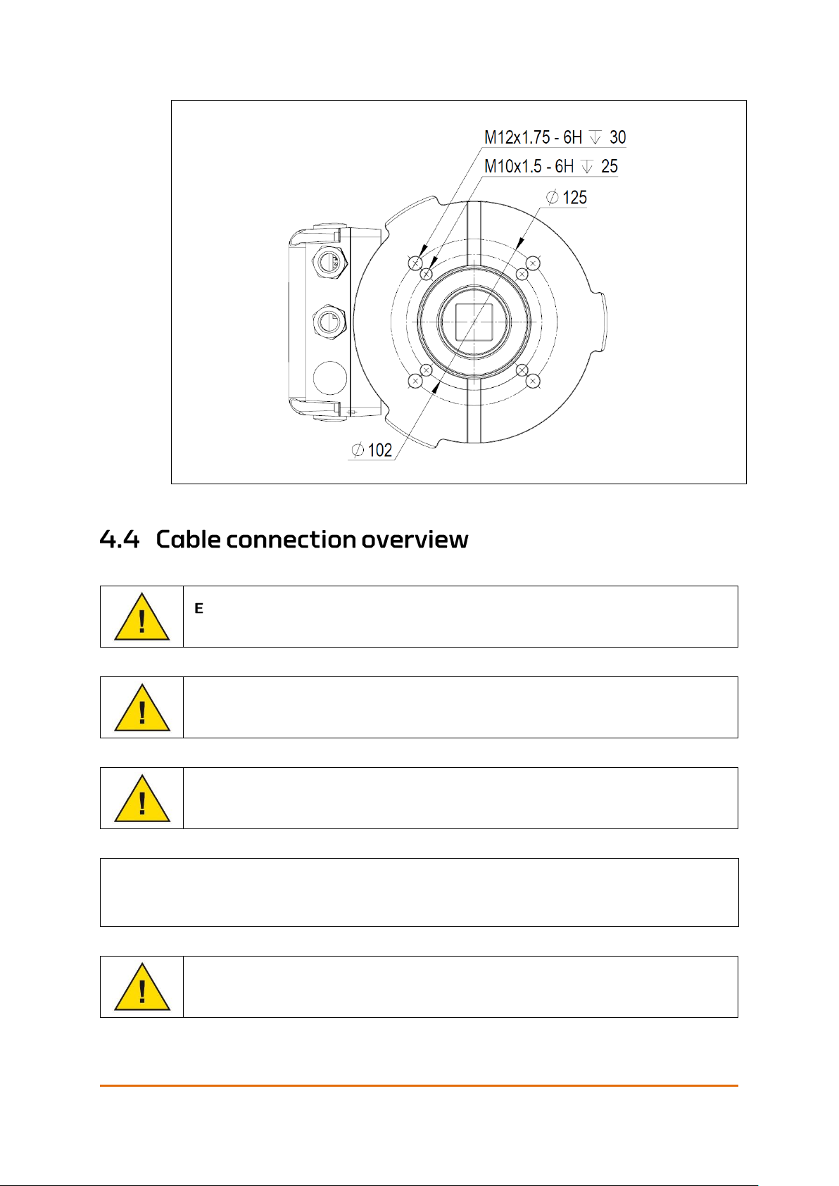
Figure 21: QT800 Valve flange fastening holes
nsure that electricians have certifications according to applicable laws
and regulations before being allowed to do any work on installations.
The supply voltage must be 1-phase, 110 – 240V AC, 50/60 Hz,
Max 240 VA.
Make sure the fuses are disconnected before you open the
Communication Interface Box.
If ferrules are used the sole responsibility for a correct installation lies on
the installing party.
Caution! When using stranded wires, make sure that all wire strands are properly
fastened in the spring connector. Using ferrules is not recommended.
Mounting and Installation
Page 36 of 86
User Manual QT250 and QT800, ID 2021 2.0 July 2018
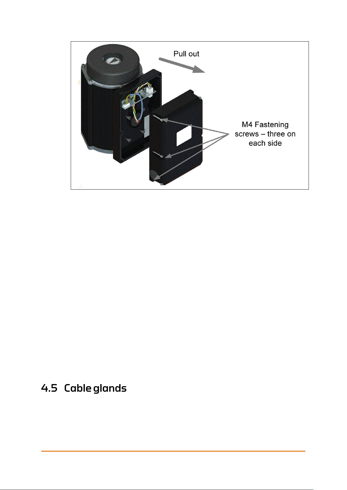
Figure 22: Removing the communication interface box
1. Loosen the six fastening screws (three on each side) on the
communication interface box, see Figure 22 above.
2. Remove the box by pulling it straight out.
3. Install the required cable glands, see section 4.5.
4. Strip all wire-ends to 8 – 9 mm/0.31 – 0.35 in.
5. Install the power supply cables through the cable glands on the right side
and connect them to the L, N and G/ PE terminals, see section 4.6.
6. Install the control signal cables through the cable glands on the left and
connect them according to the type of communication interface box used
in the installation. See section 4.8.
7. Connect the configuration medium to X2 configuration connector if
applicable.
Note! When re-assembling the communication interface box with the actuator, make
sure that no wires are jammed between the surfaces and that the screws are
cross-tightened. It is also recommended to apply some seal lubrication on the
gasket to ensure that the actuator remains water proof.
8. Replace the box and tighten the fastening screws to the specified torque.
See Table 22: Screw torque on page 81. Also see the note above.
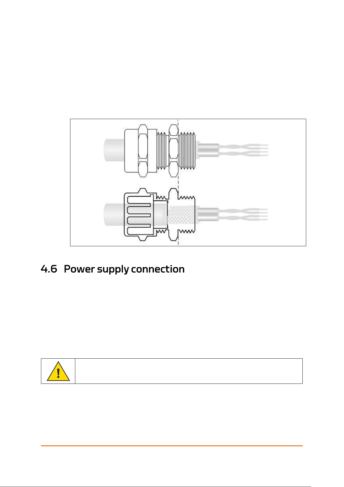
For trouble-free operation, it is important to install the glands and cable
correctly. Eltorque’s IP certification may be voided if the instructions of the
glands are not followed.
Note! Support the cable to prevent it from twisting
• Ensure that the correct cable and gland are at hand.
Mounting and Installation
User Manual QT250 and QT800, ID 2021 2.0 July 2018
Page 37 of 86
• Be sure to allow sufficient length striped cable.
• Pass the cable through the cable gland and ensure that the cable is correctly
positioned in the gland. Eltorque recommends having a 5mm cable edge
over the end of the gland.
• Hold the body of the gland in position with a spanner (24mm / 0.94 in.) or
wrench to prevent rotation and tighten the back-nut to min 5Nm, maximum
15Nm.
• Finalize the gland installation with a visual verification to ensure correct
positioning of all parts.
• For other glands follow the instructions from the supplier.
Figure 23: Mounting of cable gland
Note! Connection of the power supply is identical for all types of communication
interface box for QT250 and QT800 actuators.
Each actuator has a double power supply connector enabling bus power
connection of multiple actuators. Verify that the voltage levels are in accordance
to the products requirements.
All terminals can accommodate:
• Fine-stranded conductor
0.25 … 2.5 mm²/0.0098 - 0.0984 in2.
If ferrules are used the sole responsibility for a correct installation lies on
the installing party.
Mounting and Installation
Page 38 of 86
User Manual QT250 and QT800, ID 2021 2.0 July 2018
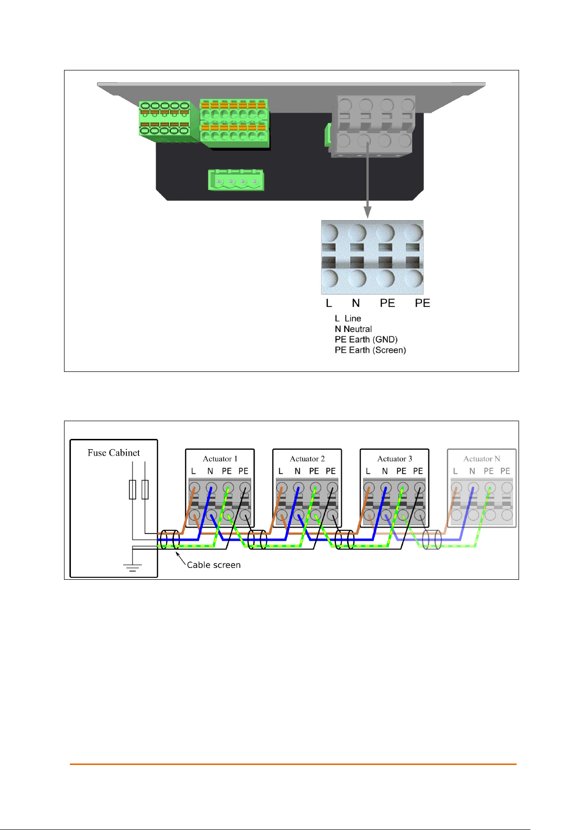
Figure 24: Power supply connection QT250 and QT800
Figure 25: Multiple actuators with bus power connection
Refer to Appendix D Earthing Methods in Maritime Installations on page 83 for
information on connection of screen for the last actuator in the loop (actuator N).
Mounting and Installation
User Manual QT250 and QT800, ID 2021 2.0 July 2018
Page 39 of 86
For maximum personnel and equipment protection, the installation shall
comply with “Guidelines for earthing in maritime installations” published
by The Norwegian Electrical Safety Directorate. Failing to do so may void
the warranty.
Exception: Field equipment shall be grounded through the supply cable.
All bare metal wires, screens or others not covered by the terminal shall be
thoroughly covered in a shrink tube to avoid unintended contact between wires,
housing or similar.
Only one conductor is allowed in each terminal of a terminal block/row for
external connections. This is not related to terminals that are integrated parts of
internal components of the equipment (such as relays and contactors).
Also see Appendix D Earthing Methods in Maritime Installations on page 83.
Note! Not following the recommended earthing guidelines may result in unwanted
system behavior.
• Strip the wire-end to 8 –9 mm (0.31in – 0.35in).
• Insert the wires according to the labelling.
All terminals can accommodate wires of cross section
0.5 – 2.5 mm2/0.02 - 0.10 in2. The cable must follow the ISO 11898-2 standard.
If ferrules are used the sole responsibility for a correct installation lies on
the installing party.
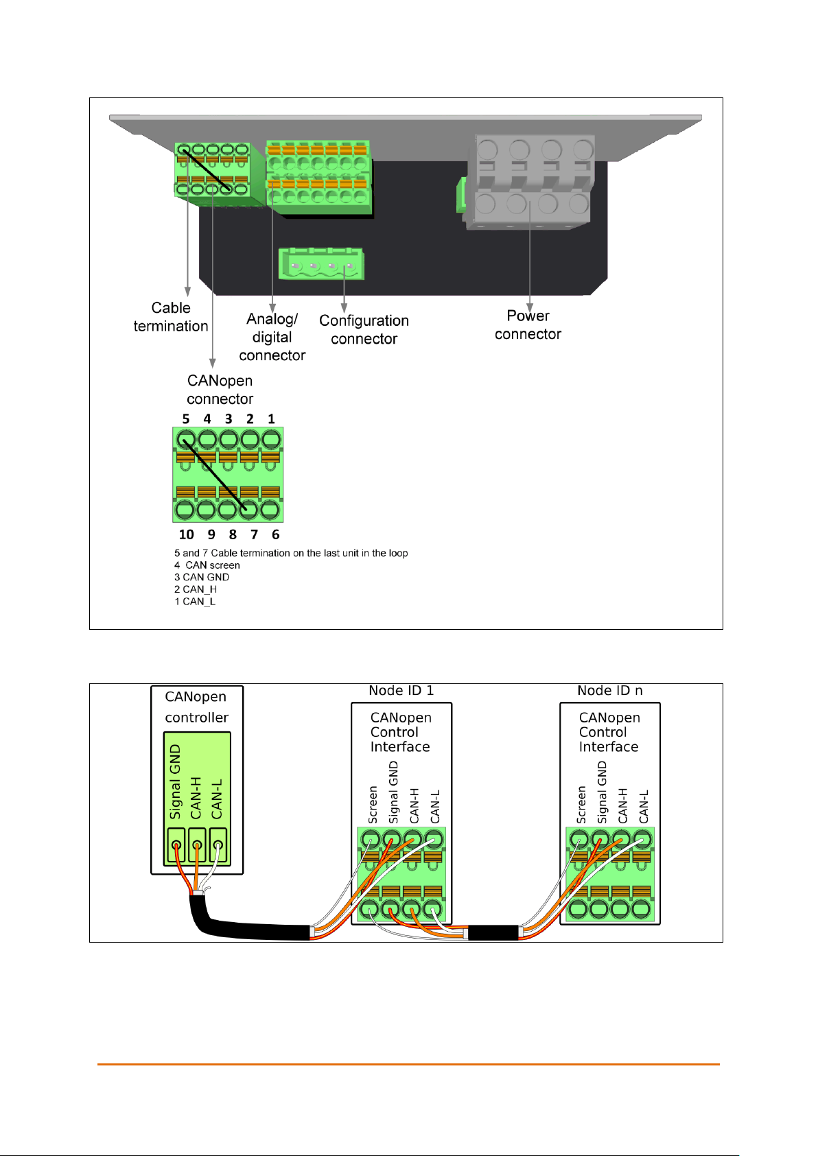
Note! The cable termination is set on the last unit in the loop by using a 0.75mm
2
wire
and connect pin 5 with pin 7 on the CANopen connector, see Figure 26.
For information on how to set the node ID, please consult the Eltorque E3C
Manual.
Mounting and Installation
Page 40 of 86
User Manual QT250 and QT800, ID 2021 2.0 July 2018
Figure 26: CANopen connection interface terminals
Figure 27: Example of CANopen network connections

Mounting and Installation
User Manual QT250 and QT800, ID 2021 2.0 July 2018
Page 41 of 86
Specifications for IOs are given in chapter 7.2.2 Digital interface on page 51.
Figure 28: Digital connection interface terminals
The digital interface can be used in various control circuits as shown below:
Figure 29: Digital interface options
Caution! The Common input terminal (#1 on X1) is active and has an internal power
supply of 15 V/ 50 mA. Do not attempt to connect an external supply to this
terminal as it can damage the communication interface box. Digital outputs
are passive and need external power supply for operation of equipment.

Mounting and Installation
Page 42 of 86
User Manual QT250 and QT800, ID 2021 2.0 July 2018
Specifications for IOs are given in chapter 3.7.1
Figure 30: Analog connection interface terminals
Figure 31: Example of 4-20 mA analog control circuit.

User Manual QT250 and QT800, ID 2021 2.0 July 2018
Page 43 of 86
Eltorque actuators can be operated in several ways:
• As part of a system directly via IAS.
• Via an Eltorque E-VCS which controls the unit.
• Using the E3C tool, which is described in the EC3 Manual.
• Emergency operation where you can operate the actuator manually.
• Failsafe operation is described in Appendix A on page 59.
The control commands and procedures depend on the type of control system
that is used. In this chapter the manual emergency operation is described.
In case of power failure, control system error or another fault preventing normal
operation of the actuator, it is possible to manually operate the actuator without
the need of additional tools.
Table 10: Input and output torque for handwheel
Input torque on handwheel
Output torque on actuator
QT250
QT800
1 Nm
75 Nm
225 Nm
2 Nm
150 Nm
450 Nm
3 Nm
225 Nm
675 Nm
4 Nm
300 Nm
900 Nm
Note! A manual operation will most likely result in an error message in the system.
1. Remove the hand-wheel cover by grabbing the tabs and pulling it straight
up.
2. Turn the hand-wheel clockwise to close or counter-clockwise to open the
valve. The valve position can be seen on the visual indicator in the center of
the hand-wheel and reference is made to the scale, see Figure 33: Position
scale.
Caution! Do not subject the hand wheel to more than the valve MAST or maximum
4Nm on the handwheel, as you may damage the actuator or valve. Below is
a table showing approximate output torque on input torque.

Operation
Page 44 of 86
User Manual QT250 and QT800, ID 2021 2.0 July 2018
3. When the manual operation is completed, refit the hand-wheel cover by
pressing it down until it stops against the actuator’s top cover.
Figure 32: Manual operation of the actuator
Figure 33: Position scale
The following subsections describe what triggers an alarm, reactions from the
actuator and how the alarm is reset.
• Trigger conditions: One or more of the alarms POSITION UNDEFINED,
TEMPERATURE or TORQUE is active.
• Reaction from actuator: None for the GENERAL alarm itself, but the other
alarms that are active have reactions.
• Reset conditions: The alarms POSITION UNDEFINED, TEMPERATURE and
TORQUE must be inactive.
• Trigger conditions: The outgoing shaft of the actuator is out of range.
• Reaction from actuator: None besides an active alarm.
• Reset conditions: The outgoing shaft must be run back within range.

Operation
User Manual QT250 and QT800, ID 2021 2.0 July 2018
Page 45 of 86
Valve percent position is a [0%, 100%] value. A value of 0% corresponds to
CLOSED position, while a value of 100% corresponds to an OPEN position. Seen
from the top of the actuator, the outgoing shaft moves in a counter-clock-wise
(CCW) direction from CLOSED position to OPEN position (see Figure 33: Position
scale on page 44.
A position encoder is connected to the outgoing shaft of the actuator and maps
positions from 0° to 359° on the outgoing shaft. For each unit, correct CLOSED
and OPEN positions for the valve must be configured in the firmware of the
actuator for proper functionality.
The position encoder reads out the absolute positional information. This means
that if the outgoing shaft is moved while the actuator is powered off, the correct
position is still shown when the actuator is powered on again.
• Trigger conditions: The alarm is activated when the temperature of the
actuator is near the max operating temperature of the internal electronics.
This may happen if the environmental temperature is higher than the max
rated temperature for the actuator or if the actuator has been run with a
higher duty cycle than specified in section 3.3.
• Reaction from actuator: The voltage to the motor is cut off if the
temperature increases above the max operating temperature of the internal
electronics. The motor can run again when the temperature alarm is inactive.
• Reset conditions: The temperature must decrease well below the max
operating temperature of the internal electronics.
• Trigger conditions: The actuator has been running but has stopped
unexpectedly. This may be caused by too high braking torque on the
outgoing shaft or failure in the motor control and feedback system.
• Reaction from actuator: The actuator stops running.
• Reset conditions: A new position command (OPEN, CLOSE, GOTO, STOP).
The motor can then run again, given that the trigger conditions for the alarm
has disappeared.

Operation
Page 46 of 86
User Manual QT250 and QT800, ID 2021 2.0 July 2018
The Eltorque actuator is a robust maintenance-free product, but you might
encounter some issues with the unit. Below is a list of the most common issues
that may occur and how to solve them. If you still have problems, please contact
Eltorque support for further help.
Table 11: Troubleshooting overview
Problem description
Cause and solution
No response from the actuator either on the
control system or if you connect with E3C.
No change in resistance on the hand wheel if
you cycle the power supply.
No power supply, check fuses and wiring.
Supply voltage can be checked using a voltage
meter.
L-N voltage should be 1-phase,110 – 240V AC,
50/60 Hz, Max 240 VA.
The actuator’s alarm output is active, on a bus
system it gives torque alarm.
The actuator attempts to move valve when a
control signal is given.
The valve operation torque is too high, please
check the torque by manual operation.
Be aware that foreign objects in the pipe can
block the valve and that valve torque changes
over time.
OR
The actuator torque has been set too low,
increase it by using the E3C configuration
software as described in the Eltorque E3C
Manual.
On bus control systems, torque can be adjusted
via the bus communication.
The actuator can operate the valve, but the
operation time is longer or shorter than desired.
Change the actuator’s speed by using the E3C
configuration software as described in the
Eltorque E3C Manual.
On bus control systems, speed can be adjusted
via the bus communication.
The actuator’s alarm output is active, on a bus
system it gives temperature alarm.
The actuator responds normally to control
signals.
The actuator’s internal temperature is
10 C/50 F or less from the motor current shut-
down limit.
If possible, allow the actuator to cool down by
leaving it in standby mode for 15 minutes or
more.
The actuator’s alarm output is active, on a bus
system it gives torque alarm.
The actuator responds only with a small position
change
The encoder cable is not properly connected or
could be damaged. Check the cable and
connector for corrosion or damage.
The actuator’s alarm output is active, on a bus
system it gives temperature alarm.
The actuator does not respond to control
signals.
The actuator has over-heated and the motor
current is shut down to prevent damage.
Make sure the surrounding temperature is within
limits and that the duty type requirements are
followed. See section 3.3Technical specification
on page 19 for more details.
The actuator with bus interface does not
respond to control signals.
The actuator responds normally when tested
with E3C.
Incorrect bus settings, please check the
configuration described in the Eltorque E3C
Manual.
OR
Bus control system is not wired or configured
correctly.

Operation
User Manual QT250 and QT800, ID 2021 2.0 July 2018
Page 47 of 86
Problem description
Cause and solution
The actuator with digital or analog interface
does not respond normally to control signals.
The actuator responds normally when tested
with E3C.
Incorrect digital or analog inversion settings,
please check the configuration described in the
Eltorque E3C Manual.
OR
The digital or analog control system is not wired
or configured correctly.
The actuator does not respond neither to control
signals nor when tested with E3C.
Restart the actuator (power on/off).
Verify the power supply with a voltage meter. If
the power is OK, the communication interface
box is defect and must be replaced.
After replacement of interface, the actuator does
not operate correctly.
The interface has not been configured correctly,
please refer to chapter 3.8 Configuration.
Contact the local Eltorque agent for support if
required.

Operation
Page 48 of 86
User Manual QT250 and QT800, ID 2021 2.0 July 2018
This page is left intentionally blank
User Manual QT250 and QT800, ID 2021 2.0 July 2018
Page 49 of 86
The QT250 and QT800 actuators are in principle maintenance-free. All bearings
and gears are lifetime lubricated and components are designed to last
throughout the actuator’s lifetime. It is however recommended that the actuator
is inspected regularly to reveal any damages caused by for example mechanical
impact or corrosion.
• Inspection
• Lubrication
• Care and cleaning of anodizing
• Maintenance of battery in a Failsafe system, see chapter B.8 Maintenance on
page 74.
• The actuators should be regularly inspected once a year:
- Check that the bolts connecting the actuator and valve together are
fastened according to required torque.
- Check that the top cover gasket and operation shaft are lubricated. If they
seem to be dry, follow the procedure in 6.4.
- Check for corrosion or other physical damage.
- Perform a test run for each actuator from the control unit.
• If the actuator has been submerged to sea water, Eltorque recommends that
the unit is inspected for damage by Eltorque qualified personnel.
See Appendix C Torque and Screw Recommendations on page 81.
The top cover gasket and manual operation shaft seal should be lubricated if
they appear to be dry. Use suitable silicone lubricants for O-rings such as
MOLYKOTE 55 O-RING grease or Super Lube silicone lubricating compound.
For cleaning purposes use organic solvents such as mild soap or detergent,
alcohol, acetone or MEK (methyl ethyl ketone).
Caution! Do not use ammonia, alkaline cleaners, lye or strong acid for cleaning
Caution! Do not use high pressure power washer directly on the actuators as the
product is not IP69K rated.

Maintenance
Page 50 of 86
User Manual QT250 and QT800, ID 2021 2.0 July 2018
This page is left intentionally blank
User Manual QT250 and QT800, ID 2021 2.0 July 2018
Page 51 of 86
Eltorque actuators have been designed to withstand harsh environments. All
products have undergone and passed severe 700 hrs. salt mist tests according to
DNVGL-CG-0339. Different types of surface treatment have been used.
Aluminum parts are typically anodized or CED coated, and steel parts are treated
with Dacromet and painted.
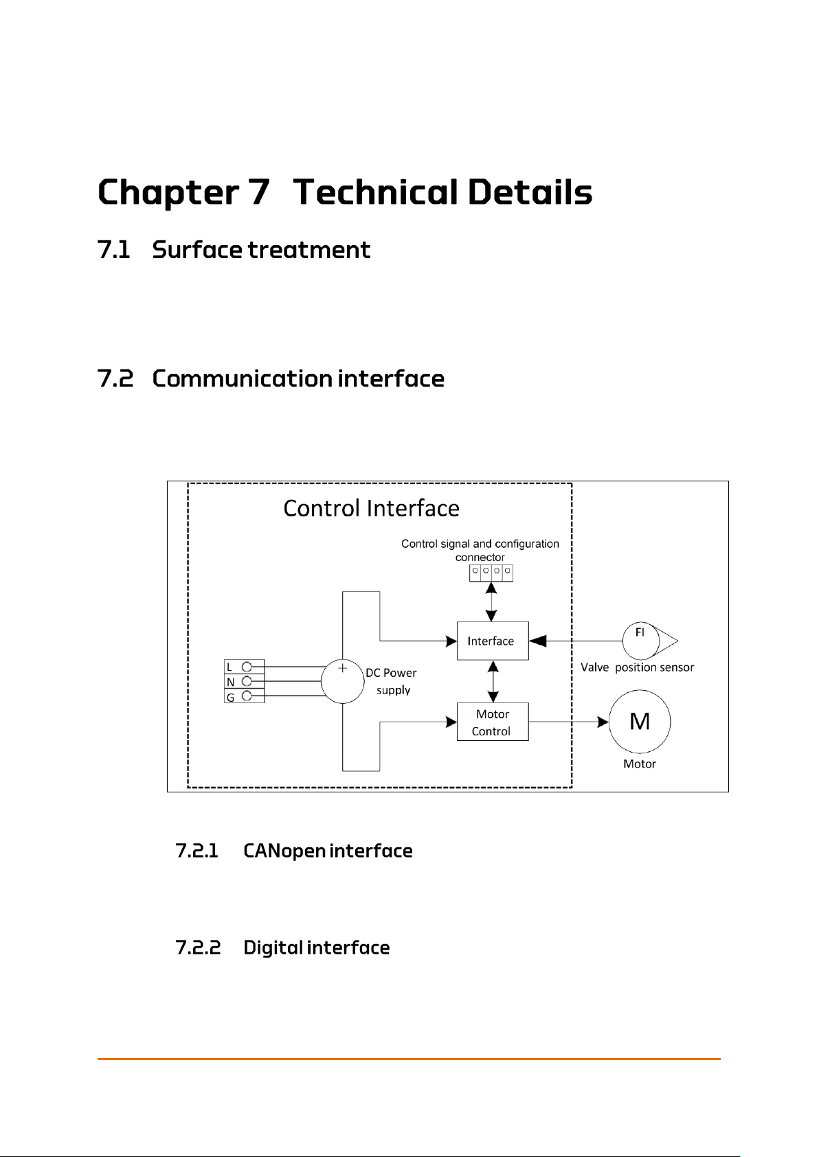
The Eltorque communication interface consists of three main modules:
1. Power supply
2. Motor control
3. Interface
Figure 34: Communication interface schematics
For more technical information about the Eltorque CANopen communication,
refer to the “System Integrators Manual CANopen interface” ID 1691.
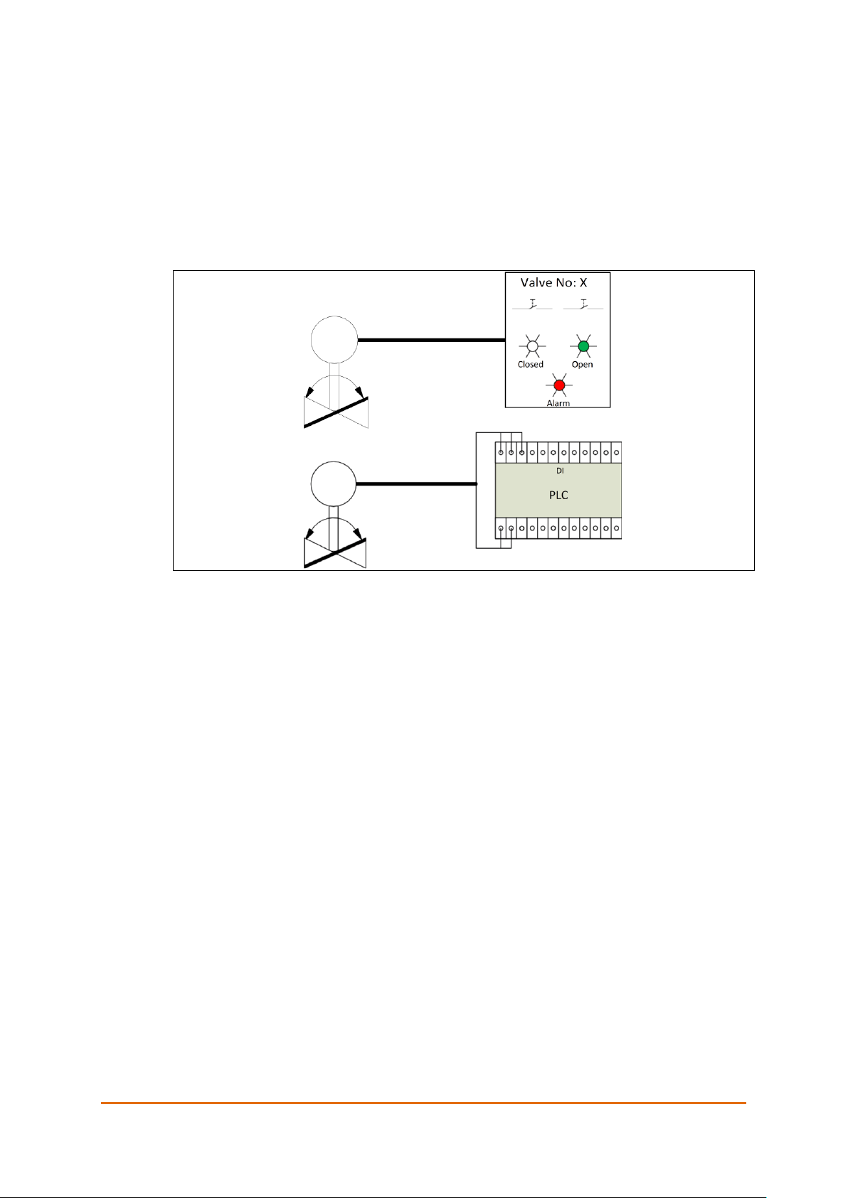
The following functions are available:
• CLOSE and OPEN command (inputs):
Technical Details
Page 52 of 86
User Manual QT250 and QT800, ID 2021 2.0 July 2018
- Is trigged by a positive edge followed by an active signal for at least 100
Ms.
- The actuator stops and sets ALARM status if OPEN signal is activated
during a CLOSE command, or CLOSE signal is activated during an OPEN
command.
• CLOSED signal and OPEN signal (outputs)
• ALARM signal (output)
- Activated if GENERAL ALARM is triggered.
Figure 35: Digital control using buttons and lamps or PLC
As shown on the illustration above, actuators with digital interface can be
controlled directly from a conventional panel with buttons/ switches and
indicator lamps. Alternatively, it can be controlled from a controller with Digital
inputs and outputs. This allows extended functionality in terms of automatic
control and visual user interface on display.
In case both the Close and Open signals are active simultaneously, the actuator
opens. Both input and output signals can use pulses of minimum 100ms length
or constant signals.
The outputs provide feedback of the actuator’s status, such as Closed, Open
and/or Alarm.
The following failure scenarios trigger an alarm:
• Manual emergency operation
• Valve position out of defined operation area
• Valve blocked
• High temperature
• Power failure (if alarm output is inverted)
• 4 – 20 mA control signal is lost

Technical Details
User Manual QT250 and QT800, ID 2021 2.0 July 2018
Page 53 of 86
Figure 36: Analogue level and flow control.
Note! The accuracy of an actuator with analog interface is +/- 5%, (if the control signal
is 12 mA/ 50%, the valve position is in the range of 45-55%).
If a higher accuracy is needed, please consider a CANbus interface with accuracy
of +/- 0.5% instead.

Technical Details
Page 54 of 86
User Manual QT250 and QT800, ID 2021 2.0 July 2018
This page is left intentionally blank

User Manual QT250 and QT800, ID 2021 2.0 July 2018
Page 55 of 86
For spare parts, not in the list below, please contact your local Eltorque
representative.
Eltorque can deliver SDoC, MD and AFD. With reference to IMO Resolution MEPC
269(68), SOLAS Reg. II-/3-5 and IACS SC 249 or latest valid revision.
2
Figure 37: Actuator spare parts
Table 12: CANopen actuators
Part No.
Description
Comment (text in BOM)
250.120.5A
QT250 2.5 CANopen Actuator1
QT250 2.5 CANopen
Actuator
250.120.5AH
QT250 2.5 CANopen Actuator for
Hybrid Marine Cable 2
QT250 2.5 CANopen
Actuator 2
800.120.5A
QT800 2.5 CANopen Actuator1
QT800 2.5 CANopen
Actuator
800.120.5AH
QT800 2.5 CANopen Actuator for
Hybrid Marine Cable 2
QT800 2.5 CANopen
Actuator 2

Ordering Information and Recommended Spare Parts
Page 56 of 86
User Manual QT250 and QT800, ID 2021 2.0 July 2018
Table 13: Digital/analog actuators
Part No.
Description
Comment (text in BOM)
250.150.5A
QT250 2.5 Digital/Analog Actuator3
QT250 2.5 Digital/Analog
Actuator
800.150.A
QT800 2.5 Digital/Analog Actuator3
QT800 2.5 Digital/Analog
Actuator
1
with: 1blind cable gland, IP68, Non-EMC, RoHS
+ 4 standard Eltorque cable glands. Nickel plated brass, IP68, Non-EMC, RoHS. Clamping
range 8 – 14mm/0.32- 0.55 in.
2
with 3 blind cable glands, IP68, Non-EMC, RoHS
+ 2 Eltorque cable glands. Nickel plated brass. IP68, Non-EMC, RoHS. Clamping range 8 –
14mm/0.32- 0.55 in.
3
with 5 blind cable glands, IP68, Non-EMC
As standard the interface box is delivered with non-EMC glands. If you require
EMC glands, please notify your sales contact when ordering, or at the latest 2
working weeks prior to delivery.
When the communication interface box is replaced, it must be re-configured by
using E3C. The Eltorque Configuration Cable which is needed to connect to the
actuator must be ordered separately if not already at hand.
Table 14: CANopen interface boxes
Part No.
Description
Comment (text in BOM)
250.020.5A
QT250 2.5 CANopen Communication
Interface Box1
QT250 2.5 CANopen
Interface
250.020.5AH
QT250 2.5 CANopen Communication
Interface Box for Hybrid Marine Cable2
QT250 2.5 CANopen
Interface
800.020.5A
QT800 2.5 CANopen Communication
Interface Box1
QT800 2.5 CANopen
Interface
800.020.5AH
QT800 2.5 CANopen Communication
Interface Box for Hybrid Marine Cable2
QT800 2.5 CANopen
Interface
Table 15: Digital/analog interface boxes
Part No.
Description
Comment (text in BOM)
250.050.5A
QT250 2.5 Digital/Analog
Communication Interface Box3
QT250 2.5 Digital/Analog
Interface
800.050.5A
QT800 2.5 Digital Communication
Interface Box3
QT800 2.5 Digital
Interface
1
with: 1 blind cable gland, IP68, Non-EMC, RoHS
+ 4 standard Eltorque cable glands. Nickel plated brass, IP68, Non-EMC, RoHS. Clamping
range 8 – 14mm/0.32- 0.55 in.
2
with 3 blind cable glands, IP68, Non-EMC, RoHS
+ 2 standard Eltorque cable glands. Nickel plated brass. IP68, Non-EMC, RoHS. Clamping
range 8 – 14mm/0.32- 0.55 in.
3
with 5 blind cable glands, IP68, Non-EMC

Ordering Information and Recommended Spare Parts
User Manual QT250 and QT800, ID 2021 2.0 July 2018
Page 57 of 86
Table 16: Accessories
Part No.
Description
Comment (text in BOM)
30003
QT250 and QT800 Protective Cover for
handwheel.
QT250 and QT800
Protective Cover
900.000
Service kit with Configuration Cable
Service kit QT-series
900.001
Eltorque Configuration cable for QTseries actuators
Config. Cable QT-series
35036
QT250 and QT800 Actuator label
Label 60 x 80 mm
Premium Extra
3 Motor Unit
Table 17: Motor units
Part No.
Description
Comment (text in BOM)
250.000.5A
QT250 2.5 Motor Unit
QT250 2.5 Motor Unit
800.000.5A
QT800 2.5 Motor Unit
QT800 2.5 Motor Unit

Ordering Information and Recommended Spare Parts
Page 58 of 86
User Manual QT250 and QT800, ID 2021 2.0 July 2018
This page is left intentionally blank

User Manual QT250 and QT800, ID 2021 2.0 July 2018
Page 59 of 86
The Eltorque QT250 and QT800 actuators are available with more than one
safety/emergency solution.
The standard product comes with:
• An emergency hand wheel for manual operation
• A self-lock function that ensures that the actuator is kept in position.
Additionally, the following options are available:
• A Dual CAN option, providing a more robust CAN network.
• A Failsafe option, providing and UPS back-up battery.
This appendix describes the Dual CAN option. The Failsafe option is described in
0 on page 64.
Note! It is not possible to upgrade an already installed standard actuator with Failsafe
or Dual CAN options. This must be included when ordering.
Table 18: Terms and abbreviations
Term
Description
Dual CAN
Each unit acts as a repeater and writes and reads on both CAN modules. One
special feature of the Dual CAN is that it separates a defective unit/segment from
the rest of the ring so that the remaining network can continue working as
normal.
With the Dual CAN option, redundancy support is improved, which makes the
actuator system more robust to errors.
A small hardware modification in the CAN interface improves the redundancy
support and makes a loop of actuators more robust to short circuits in the cable.
The actuators can be connected in a bus topography like before, but the Dual
CAN interface also enables a ring topography. This allows a redundant PLC to be
connected at the other end, which in turn makes it possible to retain full control
of all actuators in the event of a signal cable failure (short circuit, breakage etc.).
In previous CAN interfaces, which the Dual CAN is based on, signals pass
through the node directly. A signal cable failure between any two nodes here
would take down the whole loop. However, by introducing the Eltorque Dual
CAN, the nodes may instead isolate a signal cable failure and continue to
operate.
The Dual CAN function is an add-on feature to the following actuators:
• QT250/800 2.5 CANopen Actuator

Ordering Information and Recommended Spare Parts
Page 60 of 86
User Manual QT250 and QT800, ID 2021 2.0 July 2018
• QT250/800 2.5 CANopen Failsafe Actuator
The dual can option introduces some important changes to the product. By
replacing a single CAN driver with a Dual CAN driver, the product gives the
possibility for redundancy with several PLCs. If needed the faulty unit/signal
cable segment, is automatically isolated from the rest. As each node both reads
and writes on both inputs, more than one PLC can be used to control the ring.
Note! Due to its design, some latency will occur in each node. This results in lower
number of nodes per loop compared to a standard CAN node.
The Dual CAN option opens new solutions on a system level. Below is an example
of a system with improved redundancy compared with a standard system. The
actuators should be integrated through a stand-alone sub-system delivered by
Eltorque.
The solution illustrated in Figure 38 shows a ring connection with the Eltorque
Hybrid Marine Cable and Dual CAN communication from two sides. The Eltorque
Dual CAN actuators are connected to a cabinet with Eltorque valve control system
(E-VCS). In this example, pump starters are also connected to the E-VCS. Other
equipment, such as sensors can also be connected to the E-VCS. The E-VCS
includes an HMI interface on the cabinet and can also support an HMI interface
on main control level.
Figure 38: Eltorque Dual CAN Valve Control System (E-VCS) with valve and pump control

Ordering Information and Recommended Spare Parts
User Manual QT250 and QT800, ID 2021 2.0 July 2018
Page 61 of 86
The total number of nodes in a ring configuration is less than with a bus
configuration.
Note! For the ring configuration, Eltorque recommends no more than 75 nodes on 500
m Hybrid marine cable.
Table 19: Cable requirements and recommendations for Dual CAN system
Cable parameter
Cable requirements and recommendations
Cable length
With Hybrid Marine
Cable
Maximum 500 m/1650 ft.
For other cable lengths and number of nodes contact your local
Eltorque representative and we will help you to get the correct set-up.
Cable termination
For Hybrid Marine cable nominal 120 Ω.
Both Dual CAN inputs on the actuator must be impedance matched to
the characteristic impedance of the cable used. When projected by
Eltorque this is handled by our project personnel.
The Dual CAN actuator is mounted and connected in the same way as the
standard actuators, see Chapter 4 Mounting and Installation on page 33. The
power connections are done in the same way as for the standard actuators, see
Figure 24: Power supply connection QT250 and QT800 on page 38.
Note! There must be a termination between pins 5 and 10 on the Dual CAN connector,
see Figure 39. The termination cable must be connected on all nodes in the ring.
If not connected the Dual CAN interfaces are unterminated, implying that the
impedance is not matched to the cable.
The Dual CAN actuators are delivered with two internal 120 Ω termination
resistors and the termination is set on the actuator by using a 0.75mm2 wire and
connect pin 5 to pin 10 on the Dual CAN connector.

Ordering Information and Recommended Spare Parts
Page 62 of 86
User Manual QT250 and QT800, ID 2021 2.0 July 2018
Figure 39: Dual CAN connectors
The Dual CAN actuator is operated in the same way as the standard actuators,
see Chapter 5 Operation on page 43.
Eltorque can deliver SDoc, MD and AFD. With reference to IMO Resolution MEPC
269(68), SOLAS Reg. II-/3-5 and IACS SC 249or latest valid revision.
Part No.
Description
Comment (text in BOM)
250.120.5R1
QT250 2.5 CANopen Actuator with Dual
CAN option1
QT250 2.5 Dual CAN
Actuator
250.120.5R1H
QT250 2.5 CANopen Actuator with Dual
CAN option for Hybrid Marine Cable 2
QT250 2.5 Dual CAN
Actuator
800.120.5R1
QT800 2.5 CANopen Actuator with Dual
CAN1
QT800 2.5 Dual CAN
Actuator
800.120.5R1H
QT800 2.5 CANopen Actuator with Dual
CAN option for Hybrid Marine Cable 2
QT800 2.5 Dual CAN
Actuator

Ordering Information and Recommended Spare Parts
User Manual QT250 and QT800, ID 2021 2.0 July 2018
Page 63 of 86
Part No.
Description
Comment (text in BOM)
250.120.5R2
QT250 2.5 Dual CAN and Failsafe
Actuator1
QT250 2.5 Dual CAN and
Failsafe
250.120.5R2H
QT250 2.5 Dual CAN and Failsafe
Actuator for Hybrid Marine Cable 2
QT250 2.5 Dual CAN and
Failsafe
800.120.5R2
QT800 2.5 Dual CAN and Failsafe
Actuator1
QT800 2.5 Dual CAN and
Failsafe
800.120.5R2H
QT800 2.5 Dual CAN and Failsafe
Actuator Hybrid Marine Cable 2
QT800 2.5 Dual CAN and
Failsafe
900.001
Eltorque Configuration cable for QTseries actuators
Config. Cable QT-series
1
with: 1blind cable gland, IP68, Non-EMC, RoHS
+ 4 standard Eltorque cable glands. Nickel plated brass, IP68, Non-EMC, RoHS.
Clamping range 8 – 14mm/0.32- 0.55 in.
2
with 3blind cable glands, IP68, Non-EMC, RoHS
+ 2 standard Eltorque cable glands. Nickel plated brass. IP68, Non-EMC, RoHS.
Clamping range 8 – 14mm/0.32- 0.55 in.
The Dual CAN actuator handles the CAN signal in a different way compared to
the standard CANopen actuator. The redundancy support is improved and makes
an actuator system more robust to errors. The Dual CAN actuator is otherwise
identical to the Gen 2.5 actuator.

Ordering Information and Recommended Spare Parts
Page 64 of 86
User Manual QT250 and QT800, ID 2021 2.0 July 2018
This page is left intentionally blank

User Manual QT250 and QT800, ID 2021 2.0 July 2018
Page 65 of 86
The Eltorque QT250 and QT800 actuators are available with more than one
safety/emergency solution.
The standard product comes with:
• An emergency hand wheel for manual operation
• A self-lock function that ensures that the actuator is kept in position.
Additionally, the following options are available:
• A Dual CAN option, providing a more robust CAN network.
• A Failsafe option, providing and UPS back-up battery.
This appendix describes the Failsafe option. The Dual CAN option is described in
Appendix A Dual CAN Option on page 59.
Note! It is not possible to upgrade an already installed standard actuator with Failsafe
or Dual CAN options. This must be included when ordering.
Figure 40: Actuator with Failsafe option

Failsafe Option
Page 66 of 86
User Manual QT250 and QT800, ID 2021 2.0 July 2018
Table 20: Terms and abbreviations
Term
Description
Fail
Power-loss and/or signal loss. Detection of fail initiates failsafe procedure
Failsafe
actuator
An actuator that performs a pre-programmed failsafe procedure when fail is
detected
Failsafe
procedure
When a fail is detected, the failsafe actuator performs a procedure, depending on
the configuration and setup:
− Fail-to-close
− Fail-to-open
− Fail-maintain
Fail-maintain
Keep position when fail is detected
Fail-to-close
Move to closed when fail is detected
Fail-to-open
Move to opened when fail is detected
IAS
Integrated automation system
Power-loss
Power supply is insufficient to supply required power to actuator operating
interface
Signal-loss
Physical damage on signal wire(s). Detectable in actuator operating Interface as
signal loss
SOC
State of charge
SOH
State of health
UPS
Uninterruptible power supply
All batteries and electronic equipment may contain substances harmful to the
environment. After removing used equipment, return them for disposal
according to local governmental guidelines.
The failsafe electrical actuator is based on the QT250 and QT800 model. The
main difference is that an UPS (battery and UPS management system) has been
added. With this added feature, it is possible to have the actuator go to a
predefined position in case of signal or power interruption. The focus in this
chapter is on these new components and the associated functionality changes
these components introduce to the actuator.
Note! The failsafe actuator is only available for the CANopen protocol.
The embedded failsafe actuator supports the following failsafe procedures:
• Fail-maintain: The actuator immediately stops and keeps the position. The
self-lock device supports this procedure.
• Fail-to-open: The actuator moves to the valve open position.
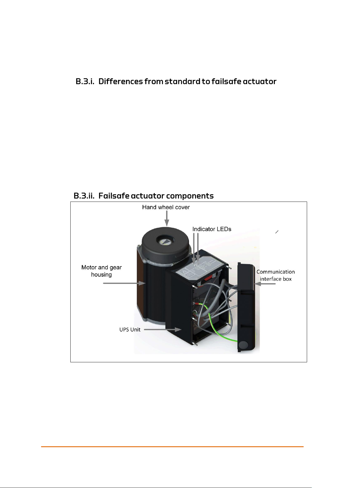
Failsafe Option
User Manual QT250 and QT800, ID 2021 2.0 July 2018
Page 67 of 86
• Fail-to-close: The actuator moves to the valve closed position.
A lead acid battery is selected for the UPS due to robust and well-proven
technology.
The failsafe module introduces changes to the overall actuator appearance and
function. The following limitations are important to consider during the design
phase.
• Location class for temperature is reduced from class D to class A when the
option failsafe is selected.
• Space needs increased, see Appendix B.4.v Space requirements on page 69.
• The battery needs a maintenance plan to maintain operationally ready, and to
be certain that the battery health’s is reported correctly. This is a requirement
from DNV GL and is needed to give alarms on battery change time.
• Storage conditions and charging of batteries in storage. A power plan must
be established concerning the installation of the failsafe actuator.
Figure 41: Actuator with Failsafe option
The bottom views for the motor and gear housing and the communication
interface box are identical to the standard version shown in Figure 5 and Figure 6
on pages 21and 21.
Failsafe Option
Page 68 of 86
User Manual QT250 and QT800, ID 2021 2.0 July 2018
The failsafe actuator is currently designed to operate quarter-turn valves, in areas
of the ship that comply with location class A for temperature.
When installing the failsafe actuator there are certain aspects to consider. Due to
it being a solution with a battery, it cannot sit without external power after
installation for an unlimited time. The product comes with the battery not
connected, and in this way if stored properly, the battery can be without power
for up to 6 months. When installed, the product enters service state and has
deep sleep mode giving a battery lifetime of up to 2 months. This state is cleared
during commissioning. The actuator is then NOT able to go back to deep sleep
mode unless the battery and power connector is detached and attached again.
But it can be put in service mode and idle mode, giving up to 1 week of battery
lifetime.
Based on this information, Eltorque recommends and accepts two ways of
installation.
1. The actuator is installed without the battery connected, not commissioned
and the power is removed for a longer period.
a. The battery is stored in a suited location awaiting permanent power feed.
The battery is installed at a later stage, but no longer than 2 months from
permanent power supply. The battery needs to be charged according to
the required specifications if storage is over the recommendations.
b. If the storage conditions when mounted on the actuator is within the
recommendations, the battery can be installed, but not connected in the
actuator. This solution requires the battery to be connected and charged
within 4 months.
2. The actuator is installed with the battery, is commissioned and the power is
kept on, or as a minimum the power is turned on and the battery recharged
every week. Alternatively, this solution can be used for up to two months if
the actuator is in deep sleep mode.
Eltorque recommends that, independent of the battery status, the battery is
replaced every 5 years during classifications to secure proper functionality when
needed.
All deviations to ideal conditions reduces the battery life time.
For the failsafe unit (with actuator or as standalone) the following storing
conditions are recommended
• The storing temperature should be 15°C/59°F.
• Battery must be fully charged before storage.
• The battery should be charged with CC/CV charging algorithm (900mA
constant current (CC) up to 14.7V. When the charging voltage reaches 14.7V
keep the voltage constant (CV) and stop charging when the charging current
reaches 90mA or after 32 hours total CC/CV charging time

Failsafe Option
User Manual QT250 and QT800, ID 2021 2.0 July 2018
Page 69 of 86
• Battery maintenance charging interval must be done every 12 months.
When the Failsafe actuator is in use, it should have maintenance charging. There
should be a timer on the charger. The Failsafe actuator must be configured to
charge either once a week or when the voltage drops below 12.5V.
Recommended charging voltage is 13.6V. If the temperature rises above 40°C, it
must be reduced to 13.2V.
For more details, please refer to the System Integrators Manual.
Figure 42: QT250 Dimensions with Failsafe option
During planning, please ensure sufficient space above and around the actuator
for installation, service and manual operation.
There must be a minimum of 150 mm/5.90 in space above and to the sides of
the actuator to accommodate room for installation, operation and service. In
front of the communication interface box there should be at least 200 mm/7.9
in.
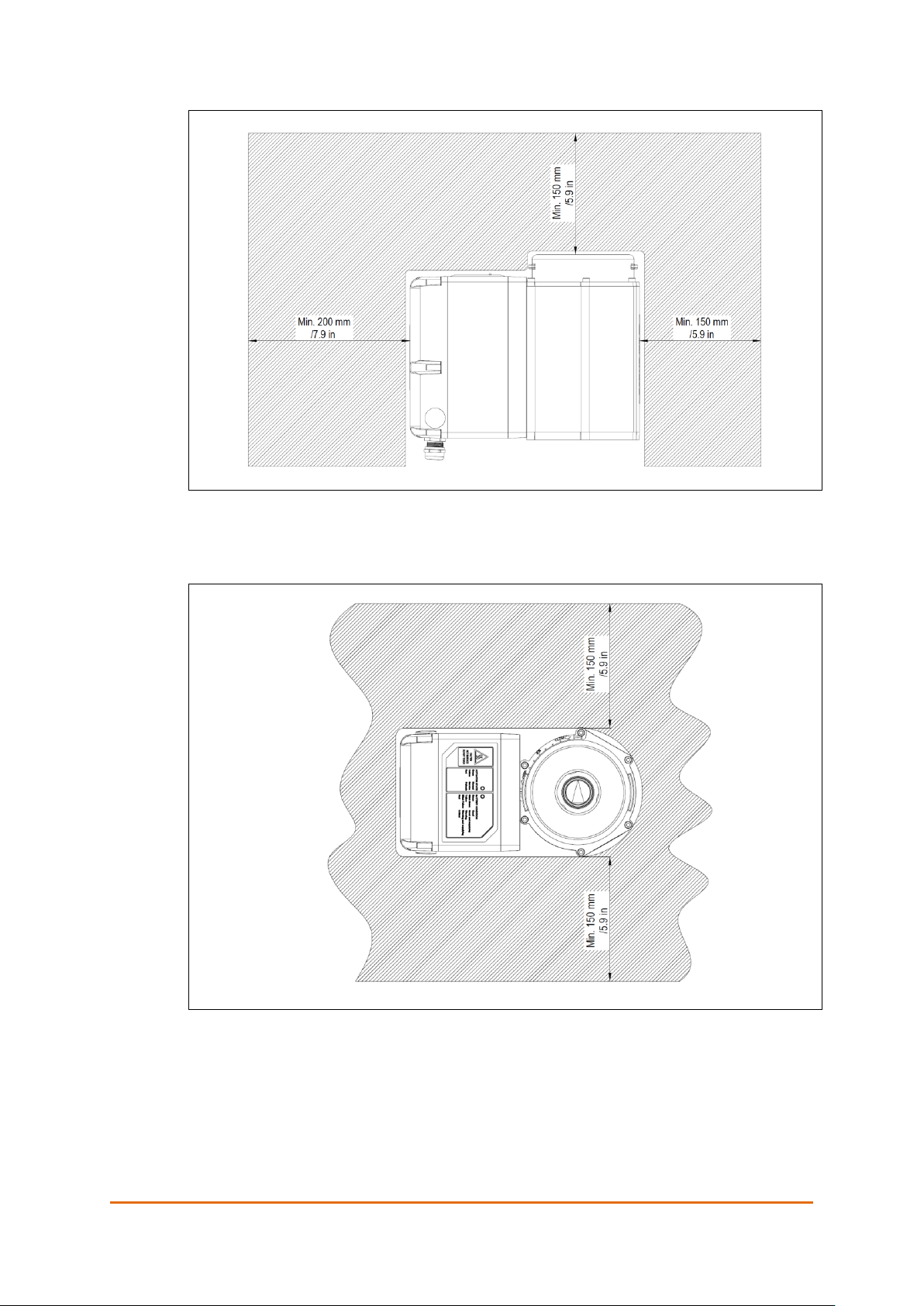
Failsafe Option
Page 70 of 86
User Manual QT250 and QT800, ID 2021 2.0 July 2018
Figure 43: QT250 and QT800 with Failsafe - Space requirements for installation, service
and manual operation
Figure 44: QT250 and QT800 with Failsafe - Space requirements for installation, service
and manual operation

Failsafe Option
User Manual QT250 and QT800, ID 2021 2.0 July 2018
Page 71 of 86
The following information is reported from the actuator to IAS:
• State (normal, failsafe or service)
• Communication with UPS lost
• Communication with UPS restored
• Communication with IAS restored
• PSU voltage low
• PSU voltage good
• Battery voltage low (SOC)
• Battery voltage good (SOC)
• Battery warning (SOH)
• Battery failure (SOH)
• Temperature high
• Temperature warning
• Temperature OK
• Temperature
• UPS error timeout counter
• Configuration checksum error
The IAS sends the following instructions and signals to the actuator:
• Set failsafe state (for test purposes)
• Clear failsafe state
• Set service state
• Clear service state
• Go-ahead signal for battery maintenance procedure (battery discharge)
• Heartbeat
Also see System Integrator’s Manual for CANopen interface for more information.
The Failsafe actuator is mounted and installed in the same way as a standard
actuator, see Chapter 4 Mounting and Installation on page 33. There are however
some changes:
• There are routines to follow for the storage and installation caused by battery
considerations, see information in section B.4.i Installation plan on page 68.
• There are considerations to make when you open the actuator, see B.6.i
below.
• Connection of the battery cable see B.8.ii on page 75, steps 12 – 16.
Note! The interface communication box is fastened to the failsafe module with nuts
instead of screws.
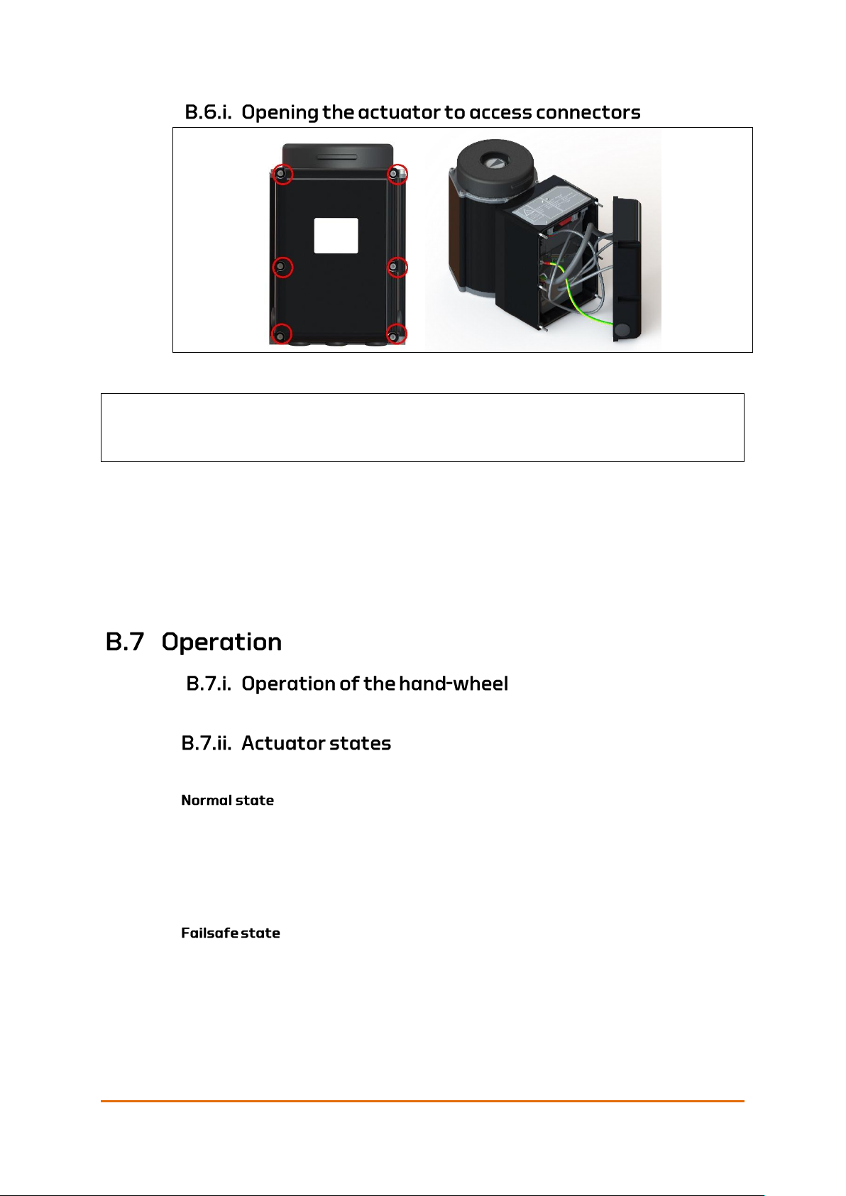
Failsafe Option
Page 72 of 86
User Manual QT250 and QT800, ID 2021 2.0 July 2018
Figure 45: QT250 – opening the failsafe actuator
Remove the six hexagon socket cap nuts holding the interface to the actuator.
The nuts are circled in red in the illustration. Remove the nuts by turning them
counterclockwise. Place the nuts in a secure location.
Required equipment:
• 4mm Hexagon Key
See Manual operation on page 43.
The Failsafe actuator has three states: Normal, failsafe and service.
This is the state the actuator is in when everything is good. If failsafe state or
service state has been activated, normal state is only resumed if failsafe or
service is cleared from the IAS.
In normal state, the UPS operates in normal mode. Normal mode for UPS means
charging (when the actuator is idle) or standby.
The actuator moves to the pre-configured failsafe position in the following cases.
• The power is lost.
• The communication signal is lost.
The actuator may also be configured to move to the pre-configured failsafe
position for internal errors in the actuator, such as:
Caution! The interface and failsafe module are loose when the nuts are removed.
Make sure not to drop the interface, or to let it hang by the cables.

Failsafe Option
User Manual QT250 and QT800, ID 2021 2.0 July 2018
Page 73 of 86
• Communication with internal UPS module is lost.
• Temperature within the actuator is too high.
• The battery for the internal UPS needs service or the battery state of charge
is below the set minimum value.
•
The failsafe state must be reset from the IAS.
If the hand wheel is turned, the actuator goes to service state. This state must be
reset from the IAS to resume the actuator to normal state after manual operation
is finished.
For more details, please refer to the System Integrators Manual.
The service state is activated remotely via the IAS, or locally by operating the
hand wheel. The service state makes the actuator accessible for inspection or
service and prohibits the failsafe state if any failsafe criteria is fulfilled. Thus, the
service state also facilitates manual operation.
Once the service state is no longer required, it is cleared remotely via the IAS.
The actuator then resumes normal or failsafe state, whichever that was active
prior to service.
B.7.iii.
The indicator LEDs are positioned at the top of the UPS unit. The label describes
the LED indications. Table 8-21 shows how the battery condition and the actuator
states are indicated by the two LEDs on the actuator.
Figure 46: QT250 and QT800 –indicator LEDs

Failsafe Option
Page 74 of 86
User Manual QT250 and QT800, ID 2021 2.0 July 2018
Table 8-21: LED indication.
Message
LED1
LED2
Battery Health Good
Green
-
Battery Health Good and
supplying
Blink Green
Battery Health Under Warning
Yellow
-
Battery Health Under Warning
and supplying
Blink Yellow
Battery Health Under Critical
Red
-
Actuator Normal
-
Green
Actuator Service
-
Yellow
Actuator Failsafe
-
Red
Problem description
Cause and solution
The actuator has been in Failsafe mode for a
longer period.
The battery must be recharged, see
B.8.i below
Lead acid batteries need to be discharged regularly as a maintenance routine.
This helps prolonging the battery life time.
A battery test and maintenance plan must be implemented according to the
battery manufacturer’s recommendations. For lead acid batteries, this implies
that the batteries must be completely discharged on a regular basis.
Battery discharge of lead acid batteries must only take place while the ship is at
port, for example during system revision shutdowns or as part of ship
maintenance routines. It implies that the actuator is nonoperational during this
procedure. The discharge routine is expected to take approximately 24 hours
and should be carried out once a year.
For more details, please refer to the System Integrators Manual.
The following procedure should be performed once a year.
1. Set the actuator in service mode.
2. Send the command «Start Battery Deep Cycle Test” (see System Integrators
Manual).
3. The actuator automatically charges the battery to 100%.
4. The bit «BATTDIS» in Failsafe index 0x25000 Status 2 indicates that the
test is performed.
5. When the battery reaches 0% the «BATTDIS» is automatically cleared, the
SOH value is updated, and the battery is recharged.
6. When the battery has reached the lower limit for SOC, service mode can be
cleared, and the actuator resumes normal operation.

Failsafe Option
User Manual QT250 and QT800, ID 2021 2.0 July 2018
Page 75 of 86
This procedure describes how to change the battery in Eltorque QT250 Failsafe
actuator.
Parts of this procedure also applies to first time installation the Failsafe actuator
as the battery cable must be connected - see steps 12 – 16.
Procedure
Step
Description
Illustration
1
Enable service mode either from the actuator control panel, or by rotating the handwheel of
the actuator.
Make sure that the actuator service indicator light is yellow on all actuators that the battery
change procedure is going to be performed on before proceeding to the next step.
2
Turn off the power going to all actuators that the battery change procedure is going to be
performed on.
3
Remove the six hexagon socket cap
nuts holding the interface to the
actuator.
The nuts are circled in red in the
illustration.
Remove the nuts by turning them
counterclockwise. Place the nuts in a
secure location.
The interface and failsafe module are
loose when the nuts are removed: Make
sure that the interface and failsafe
module do not fall off.
Required equipment:
− 4mm Hexagon Key
4
Remove the interface as shown in the
illustration.
Make sure to not drop the interface, or
to let it hang by the cables.

Failsafe Option
Page 76 of 86
User Manual QT250 and QT800, ID 2021 2.0 July 2018
Procedure
Step
Description
Illustration
5
Disconnect the battery cable connector
marked by a yellow circle in the
illustration.
6
Disconnect the rest of the cable
connectors marked by yellow circles in
the illustration.
7
Place the interface in a secure location to avoid any damage to it.
8
Remove the four M3 hex socket head
screws holding the battery bracket by
turning them counterclockwise. The
screws are circled red in the illustration.
Place the screws and connector in a
secure location.
Required equipment:
− 2,5mm Hexagon Key.

Failsafe Option
User Manual QT250 and QT800, ID 2021 2.0 July 2018
Page 77 of 86
Procedure
Step
Description
Illustration
9
Remove the battery by sliding it out of
the frame.
Replace the battery and slide the new
battery into the frame.
10
Fasten the battery holding bracket with
the four M3 hex socket head screws by
turning them clockwise. Tighten the
screws to 1,2Nm and lubricate the
threads using Molykote 1000 or similar
lubricant containing MoS2. Make sure
that the grounding connectors are
placed as shown in the illustration
before tightening the screws. The
screws are circled red in the illustration.
Required equipment:
− 2,5mm Hexagon Key.
11
Hold the interface close to the actuator
and connect the connectors marked by
yellow circles in the illustration. The two
equal connectors are distinguished by
the color on the cable sleeve. The cable
with the blue sleeve connects to the
cable with the blue sleeve, and the cable
with the black sleeve connects to the
PCB.

Failsafe Option
Page 78 of 86
User Manual QT250 and QT800, ID 2021 2.0 July 2018
Procedure
Step
Description
Illustration
12
Connect the battery connector marked
by a yellow circle in the illustration.
13
Place the interface back on the actuator.
Make sure no cables get caught on the
sealing surface between the interface
and the actuator. Make sure to not drop
the interface, or to let it hang by the
cables.
14
Fasten the interface with the six hexagon socket cap nuts by turning them clockwise. Note
the correct sequence for tightening of the nuts. See Appendix C Torque and Screw
Recommendations on page 81.
15
Turn on the power going to the actuators.
16
Disable service mode from the actuator control system. Make sure that the actuator state
indicator light is green on all actuators that have received a new battery.

Failsafe Option
User Manual QT250 and QT800, ID 2021 2.0 July 2018
Page 79 of 86
For spare parts, not in the list below, please contact your local Eltorque
representative.
Eltorque can deliver SDoc, MD and AFD. With reference to IMO Resolution MEPC
269(68), SOLAS Reg. II-/3-5 and IACS SC 249or latest valid Revision..
Figure 47: Actuator with embedded Failsafe UPS unit.
Part No.
Description
Comment (text in BOM)
250.120.5B
QT250 2.5 CANopen Actuator with
Failsafe option1
QT250 2.5 CANopen FS
Actuator
250.120.BH
QT250 2.5 CANopen Actuator with
Failsafe option for Hybrid Marine Cable 2
QT250 2.5 CANopen FS
Actuator
250.220.5B
QT250 Failsafe battery unit
QT250 2.5 CANopen FS
Module
800.120.5B
QT800 2.5 CANopen Actuator with
Failsafe option1
QT800 2.5 CANopen FS
Actuator
800.120.BH
QT800 2.5 CANopen Actuator with
Failsafe option for Hybrid Marine Cable 2
QT800 2.5 CANopen FS
Actuator
250.120.5R2
QT250 2.5 Dual CAN and Failsafe
Actuator1
QT250 2.x Dual CANopen
and Failsafe
250.120.5R2H
QT250 2.5 Dual CAN and Failsafe
Actuator for Hybrid Marine Cable 2
QT250 2.x Dual CANopen
and Failsafe
800.120.5R2
QT800 2.5 Dual CAN and Failsafe
Actuator1
QT800 2.x Dual CANopen
and Failsafe
800.120.5R2H
QT800 2.5 Dual CAN and Failsafe
Actuator Hybrid Marine Cable 2
QT800 2.x Dual CANopen
and Failsafe
800.220.5B
QT800 Failsafe battery unit
QT250 2.5 CANopen FS
Module
900.001
Eltorque Configuration cable for QTseries actuators
Config. Cable QT-series
17023982
Battery for Failsafe module
Battery 12V, 9Ah lead,
NS12-9G
1
with: 1blind cable gland, IP68, Non-EMC, RoHS
+ 4 standard Eltorque cable glands. Nickel plated brass, IP68, Non-EMC, RoHS. Clamping
range 8 – 14mm/0.32- 0.55 in.
2
with 3blind cable glands, IP68, Non-EMC, RoHS
+ 2 standard Eltorque cable glands. Nickel plated brass. IP68, Non-EMC, RoHS. Clamping
range 8 – 14mm/0.32- 0.55 in.

Failsafe Option
Page 80 of 86
User Manual QT250 and QT800, ID 2021 2.0 July 2018
This page is left intentionally blank

User Manual QT250 and QT800, ID 2021 2.0 July 2018
Page 81 of 86
The following table lists recommended torque values and minimum thread
engagement when mounting the Eltorque actuators.
Table 22: Screw torque
Thread
size
Tightening
torque.
(Nm)
Min. thread
engagement.
(mm/in.)
M4
3.4
NA
M5
5.1
7.5/0.30
M6
8.9
9/0.35
M8
21.1
12/0.47
M10
41.5
15/0.59
M12
70.7
18/0.70
M16
172.6
24/0.94
M20
336.2
30/1.18
• Use A4-80 screw material and quality.
• Use washer under bolt head/between bolt head and mounting flange.
Requirements: DIN 125A, minimum 200HV, A4.
• Lubricate washer surface and underside of bolt head with a lubricant
resulting with a friction coefficient 0.08 to 0.14 between bolt head and
washer. The lubricant must not contain aluminum, zinc or copper. To
prevent galling when using stainless steel fasteners, lubricant containing
MoS2 is recommended.
• Use thread lock Loctite 222 or similar, on bolt threads. Be sure that the
amount applied is enough, so no water can get into thread holes after the
bolt is inserted. The thread-lock’s main purpose in this application is to
serve as a barrier, preventing sea-water to act as a catalyst between bolts
and threads in the actuator base.

Torque and Screw Recommendations
Page 82 of 86
User Manual QT250 and QT800, ID 2021 2.0 July 2018
Lubricate threads with a lubricant giving friction coefficient between 0.08 to
0.14. To prevent galling when using stainless steel fasteners, lubricant
containing MoS2 is recommended.
Stainless steel fasteners tend to gall while being tightened. The risk of galling or
thread seizing can be reduced by:
• Using recommended lubrication.
• Tighten the screws in the sequence indicated in the figure below.
• Tighten fasteners with low rpm’s; without interruptions.
• Apply only light pressure, see Table 22: Screw torque on page 81.
Figure 48: Tightening sequence for M4 screws

User Manual QT250 and QT800, ID 2021 2.0 July 2018
Page 83 of 86
All bare metal wires, screens or others not covered by the terminal shall be fully
covered in shrink tube to avoid unintended contact between wires, housing or
similar.
Only one conductor is allowed in each terminal of a terminal block/row for
external connections. This is not related to terminals as integrated part of
internal components (e.g. relays, contactors) of the equipment. Two conductors
may in certain cases be used in one approved type ferrule connected to one
terminal. Contact Eltorque for approval.
• PE Earth shall be connected to the PE Earth bar in the cabinet and at the
actuator housing. PE earth shall preferably not be routed via the PCB to the
housing but go directly. The PCB shall be earthed to the actuator housing
from own cable.
• Outer braided screen shall be connected to PE earth at both ends. Heat Shrink
Tubing shall be used on visible wires inside actuator.
• Inner Screen shall be connected to IE/IS earth in the control cabinet. The
other end shall be floating in the actuator (floating thru for several items in
same loop). Heat Shrink Tubing shall be used to isolate the inner screen and
make sure that it is not in direct contact with anything inside actuator.
1. The inner screen needs to be terminated inside the actuator housing.
Products that doesn’t have enough terminals available in the connector
needs a separate connector. We recommend using Wago 221 or
equivalent.
2. It is important that the outer screen is cut and not connected to the
housing for the connection between two actuators on different power
loops. Shrink tube shall be used to cover all bare wires.
3.

Earthing Methods in Maritime Installations
Page 84 of 86
User Manual QT250 and QT800, ID 2021 2.0 July 2018


Phone: +47 7485 5520
info@eltorque.no
 Loading...