

Page 1

Documentation
Measurement and Control
Type: ELT-GP1
Content
1. Installation instructions
2. Data sheets
3. Declarations of conformity
Page 2

eltherm GmbH
info@eltherm.com
BU-020
Operating Instructions for
Revision 6
20.12.2018
BU-020
Operating Instructions for
Temperature Controller ELT-GP1
(Part No. 008Q520)
Ernst-Heinkel-Str. 6-10
57299 Burbach
T.: +49 2736 4413-0
F.: +49 2736 4413-50
Temperature Controller ELT-GP1
Page 3
BU-020
Operating Instructions for
Revision 4
20.12.2018
Temperature Controller ELT-GP1
Contents
1. Product Description .......................................................................................................... 3
1.1 Function ............................................................................................................................... 3
1.2 Control and Display ............................................................................................................. 3
2. Technical Data .................................................................................................................. 4
2.1 Terminal Connection Plan ................................................................................................... 4
2.2 Terminals: Explanation ........................................................................................................ 5
3. General Safety Instructions ............................................................................................... 6
3.1 Proper use ........................................................................................................................... 6
3.2 Hazards of electrical power ................................................................................................. 6
3.3 Modifications to the temperature controller ...................................................................... 6
4. Installation ....................................................................................................................... 7
4.1 Mounting ............................................................................................................................. 7
4.2 Installation ........................................................................................................................... 7
5. Settings and Operation ..................................................................................................... 8
5.1 Setting the temperature set-point (Target Temperature) .................................................. 8
5.2 Setting the bottom and top temperature limits (Low Limit and High Limit) ...................... 8
6. Optional Features ............................................................................................................. 9
6.1 Other housing designs ......................................................................................................... 9
6.2 Digital temperature display (ELT-ONA) ............................................................................... 9
6.3 Analogue Output (ELT-OAA) ................................................................................................ 9
6.4 Factory Optional Features ................................................................................................. 10
6.5 Analogue Output , Option ELT-OAA .................................................................................. 10
6.6 External Set Point .............................................................................................................. 10
Please read this manual carefully before using this product. Warranty claims cannot be
considered in case of damage caused by failure to comply with these operating
instructions! This documentation was compiled with utmost care, however, we cannot
guarantee for its correctness in every respect.
Instructions for use and useful or important information.
Immediate hazard which can lead to death, serious injury or considerable material
damage.
This User's Manual is intended to familiarize you with the product, the safety instructions, mounting
and installation, operation and setting, and any optional features.
Contents subject to change. ELTHERM GmbH accepts no liability for any errors in this documentation.. No liability whatsoever will be
accepted for damage incurred in direct connection with the supply or use of this documentation, unless there is a legal obligation.
Disclosure and copying of this document and the use and divulgence of its contents are not permitted , unless expressly authorized.
Failure to comply will result in liability for damages. All rights in respect of a patent or registered trademark being granted reserved.
Page 2 of 10
Page 4
BU-020
Operating Instructions for
Revision 4
20.12.2018
eltherm
Germany
modu
ELT-GP1
BETRIEB
HEIZEN
ALARM
20°
0°
100°
80°
60°
40°
c
d
e
f
2
3
4
5
6
Temperature Controller ELT-GP1
1.
Product Description
1.1 Function
In control and monitoring mode, the unit regulates connected heaters to a given set-point (i.e.
target temperature). Monitoring is done based on preset temperature limits. If a limit is
exceeded or is not reached, potential-free contacts are switched (K3). The unit can be
configured for four different types of controller in the factory.
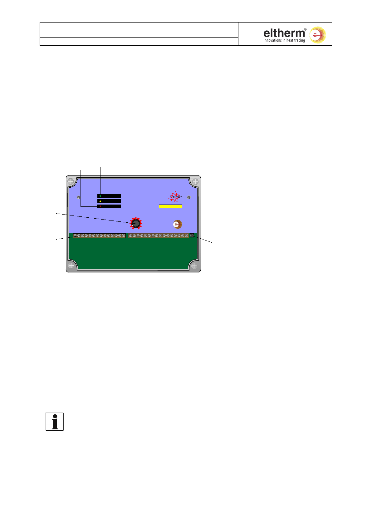
1.2 Control and Display
Fig. 1: Control and display
Pos. 1: Potentiometer for adjusting the set-point.
Pos. 2: Terminal strip for all inputs and outputs (see chapter 2.4 ‘Terminal Connection Plan’).
Pos. 3: Control key:
To switch the display from actual to target (set-point) value (if optional display is
present).
To input the bottom temperature limit (Low Limit) and the top temperature limit (High
Limit) for the permissible actual temperature.
Pos. 4: LED ‘Operation’. Lights up green when input voltage is present.
Pos. 5: LED ‘Heat’. Lights up yellow when the heater is switched on.
Pos. 6: LED ‘Alarm’
Lights up red when there is a fault at the temperature probe.
Flashes if the preset temperature limit is exceeded or is not reached.
The LED´s ‘Heat’ and ‘Alarm’ have another meaning when adjusting the set-point (refer to
chapter 5 ‘Settings and Operation’).
Page 3 of 10
Page 5
BU-020
Operating Instructions for
Revision 4
20.12.2018
Mains voltage:
230 V, 50 Hz
Power consumption:
max. 5 VA
Temperature measuring
range:
-51°C to +870°C
Controller range:
0°C to 200°C (standard configuration)
Hysteresis
2 K
Accuracy:
(1.5°C+1.5% of meas.r.)
Resolution (internal):
0.1°C (Pt100)
0.4°C (thermocouples)
Meas. current (Pt100):
approx. 0.75 mA
Controller cycle time:
approx. 1.2 s
Housing:
Plastic-walled housing with transparent cover, Pg-cable gland
Int. protection
IP 67
Ambient conditions:
0°C to 50°C,
max. 90% rel. humidity (non-condensing)
Dimensions:
180 x 130 x 75 mm (W x H x D)
Connections:
30 cage pull-terminal screws à 2.5 mm²
Inputs:
(see chapter 2.4 Terminal Connection Plan)
Outputs:
(see chapter 2.4 Terminal Connection Plan)
Interface:
(see chapter 2.4 Terminal Connection Plan)
1
2
+
-
NETZ
SSR 0-10VAnalog DigIn
Pt 100/J/KBus
G
I U
E2E1
G
3
4 5
6
7
8 9 10
11 121314
30
29
2827
26
25
24232120 2215
16 17
18 19
L
L N N PE PE
K1 K1K2K2 K3
K3 K4K4
+
-
+
-
-
+ +
-
RELAIS
2.
Technical Data
Temperature Controller ELT-GP1
with Pt100:
with thermocouple type K:
with thermocouple type J:
±(0.5°C+0.5% of meas.r.)
±(1.0°C+1.0% of meas.r.)
±
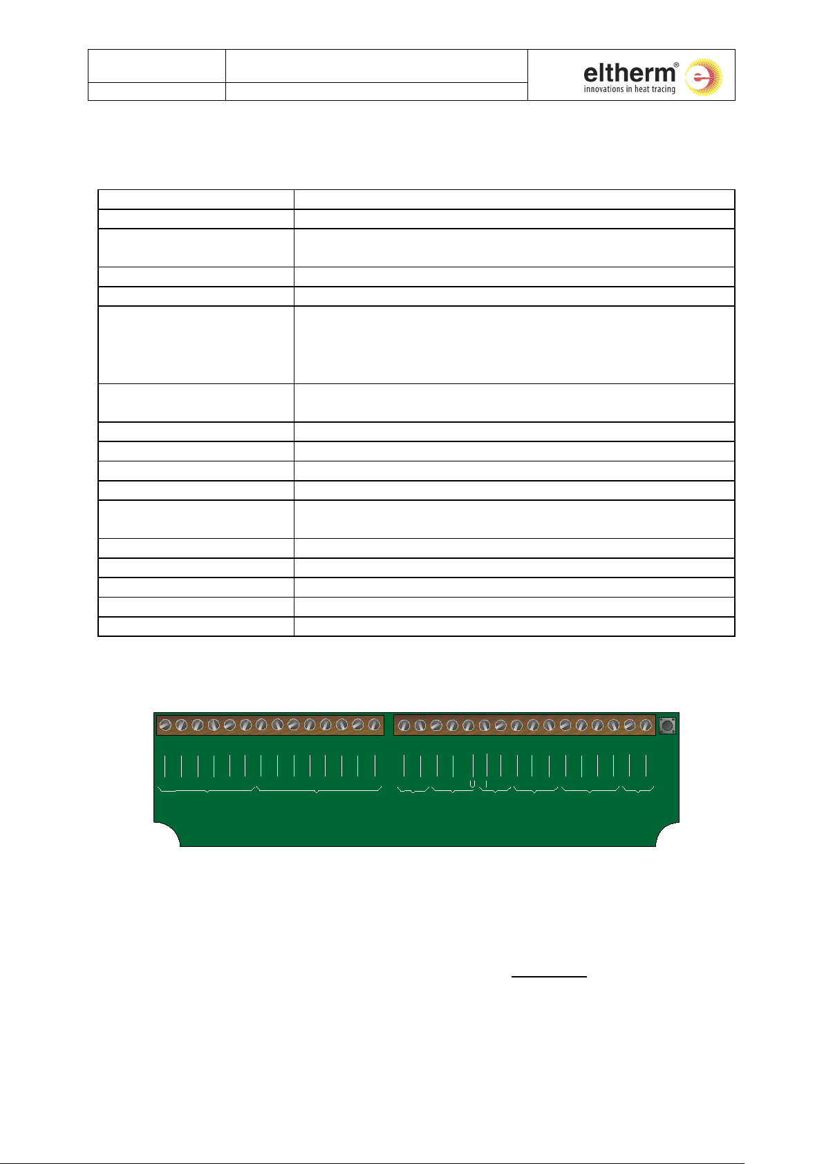
2.1 Terminal Connection Plan
Fig. 2: Terminals
The controller can be configured for various types of controllers in the factory. Depending on the
type of controller, the outputs may have different functions. The following types of controller are
available from the factory:
• 2-position controller (conventional or PID) with hysteresis (normal case)
• PID-controller with PWM (= Pulse-Width-Modulation) output (quasi-continuous)
• PID-continuous controller
Where there are differences in the outputs, you will find the abbreviations ‘2-position’, ‘PID-PWM’
and ‘PID-cont.’ in Table 1.
Page 4 of 10
Page 6

BU-020
Operating Instructions for
Revision 4
20.12.2018
Terminal No.
Name
Meaning
1 L Mains connection for the unit (phase conductor).
2 L Second "L" terminal. Possible use: The heater is to be connected directly to the unit. In this case: Jumper from
2 to 7.
3 N Mains connection for the unit (neutral conductor).
4 N Second "N" terminal. Possible use: The heater is to be connected directly to the unit. In this case:
heater at terminals 8 and 10.
5
PE
Mains protective conductor.
6
PE
Second "PE" terminal, e.g. for connecting the protective conductor for the heater.
7 (2-position)
K1
Contacts 7 + 8 as normally open contacts. Input of load relay K1, max. 16A / 230VAC. Phase connection from
mains.
8 (2-position)
K1
Contacts 7 + 8 as normally open contacts. Output of load relay K1, max. 16 A / 230VAC. Phase connection of
heater.
7,8(PID-PWM)
(PID-cont.)
K1
Contacts 7 + 8 as normally closed contacts, max. 16 A / 230VAC. Open when the preset high temperature limit
is exceeded (High Limit).
9 (2-position)
K2
Optional, if the phase and neutral conductors are to be switched (e.g. BeNeLux countries): Contacts 9 + 10 as
normally open contacts. Input of load relay K2, max. 16 A / 230VAC. Neutral conductor from mains.
10 (2-position)
K2
Optional, (see above). Contacts 9 and 10 as normally open contacts. Output of load relay, max. 16 A / 230VAC.
Neutral conductor of the heater.
9,10 (PID-PWM)
(PID-cont.)
K2
Optional, see: 7,8 (PID-PWM)
(PID-continuous)
11, 12
K3
Optional. Contacts 11 + 12 as normally closed contacts, max. 8 A / 230VAC. Open in case of probe breakage or
when the preset high temperature limit is exceeded or the preset low temperature limit is not reached.
13, 14
K4
Optional. Contacts 13 and 14 as normally open contacts, max. 8 A / 230VAC. Close when the preset high
temperature limit is exceeded (High Limit).
15,16(2position)
+, -
SSR-output, 12V, max. 30 mA for connection of a solid state relay for heater ON / OFF.
15, 16 (PIDPWM)
+, -
SSR-output, as PWM (Pulse-Width-Modulation) -signal, 12V, max. 30 mA for connection of a solid state relay
15, 16 (PIDcont.)
+, -
not used.
17 (2-position)
(PID-PWM)
U
Optional. Electrically isolated analogue output, Voltage: 0 - 10V (between terminals 17 and 19), proportional
to the actual temperature, referred to the preset control range, Max.power: 250 mW.
18 (2-
(PID-PWM)
I
Optional. Electrically isolated analogue output, current drain: 0 - 20mA (between terminals 18 and 19),
17 (PID-cont.)
U
Optional. Electrically isolated analogue output as manipulated variable, Voltage: 0 - 10V (between terminals 17
and 19). 5V would e.g. correspond to half power.
18 (PID-cont.)
I
Optional. Electrically isolated analogue output as manipulated variable, current drain:
0 - 20mA (between terminals 18 and 19). 10mA would e.g. correspond to half power.
19 G Common reference potential for terminals 17 and 18.
20 + Electrically isolated bus interface. Pay attention to polarity to avoid communication error.
21 - see above
Digital In
Optional. Electrically isolated digital input, voltage: 10 - 30VDC (at terminals 22 and 24) Function: External
heater is not being supplied with current, it is just being monitored).
23
Digital In
E2
No function at present.
24 G Common reference potential for terminals 22 and 23.
25 + Pt100 , two-wire system: terminals 26 and 27, jumper between 25 and 26 and between 27 and 28.
26 + Pt100 , three-wire system: jumper between 25 and 26, left connection to 26, right pair to 27 and 28.
27 - Pt100 , four-wire system: left pair to 25 and 26, right pair to 27 and 28.
28 - Thermocouple, type J or K: terminals 26 (+) and 28 (-).
29, 30
+, -
Set-point input, voltage: 0 - 10VDC. Function: External set-point adjustment. The applied voltage must be
proportional to the temperature set-point (target temperature), referred to the preset control range.
Temperature Controller ELT-GP1
2.2 Terminals: Explanation
A) Without using the second load relay K2 (normal case): Connect the heater at terminals 4 and 8.
B) With use of the second load relay K2 (e.g. for BeNeLux countries): jumper from 4 to 9 and connection of the
position)
22
E1
probe short (in the case of a Pt100) and for probe interruption (in the case of a thermocouple). Also open
proportional to the actual temperature, referred to the preset control range. Max. output: 250 mW.
controller enable:
If voltage is present: controller is in automatic mode. If no voltage is present: controller is in standby mode (i.e.
Table 1
Page 5 of 10
Page 7

BU-020
Operating Instructions for
Revision 4
20.12.2018
Temperature Controller ELT-GP1
3.
General Safety Instructions
3.1 Proper use
In its standard configuration, the temperature controller ELT-GP 2 is a two-position controller
used to control electric heaters. The controller also indicates temperature deviations of the
heater and any faults which may occur in the temperature probes used for this purpose. Any
other use above and beyond that is deemed improper use. Your temperature controller is
state of the art and has been built in compliance with recognized safety regulations. Its
assembly and use can nevertheless constitute a hazard to persons or cause impairment of the
unit and other material damage. The temperature controller must only be used when it is in
technically perfect working order, for the purpose for which it is intended, in awareness of all
safety and hazard aspects and in compliance with the information given in the User's Manual.
3.2 Hazards of electrical power
Work on electrical equipment must only be done by a qualified electrician or by duly trained
personnel under the instruction and supervision of a qualified electrician, in accordance with
all applicable electrical standards and regulations.
3.3 Modifications to the temperature controller
Do not modify the equipment or the software without the manufacturer's prior authorization.
Failure to comply will render all warranty claims null and void and we cannot give any
guarantees for trouble-free operation of the controller.
Page 6 of 10
Page 8

BU-020
Operating Instructions for
Revision 4
20.12.2018
Temperature Controller ELT-GP1
4.
Installation
4.1 Mounting
The housing is designed for wall mounting. Drill four holes, ∅ 4 mm, using the mounting template.
Attach housing with screws (not included). Glands are directed downwards.
4.2 Installation
Read chapter 3 ‘General Safety Instructions’ carefully prior to installation.
MORTAL DANGER!
Before connecting the mains lead, you must switch off all power to the complete control
cabinet!
First connect the ground conductor (green-yellow colour-coding) to the unit. Then connect the live
wires. Connect all necessary conductors (see chapter 2.4 ‘Terminal Connection Plan’).
Before putting the unit into operation, check that all contact screws at the terminal strips are
tight!
Page 7 of 10
Page 9

BU-020
Operating Instructions for
Revision 4
20.12.2018
Temperature Controller ELT-GP1
5.
Settings and Operation
All position numbers given here refer to Figure 1 in chapter. 2.2 ‘Controls And Displays’.
5.1 Setting the temperature set-point (Target Temperature)
• With the help of a screwdriver, or similar, briefly tap the control key (Pos. 3). The
controller is now in setup mode for the setting the set-point
• Adjust the set-point by turning the potentiometer (Pos. 1).
• Tap the control key (Pos. 3) again to take over the set-point which you have just set.
The turning range of the potentiometer corresponds with the preset temperature control
range. Example: Temperature range: 0°C – 200°C; Left limit stop of the poti: 0°C; Right limit
stop of the poti: 200°C
5.2 Setting the bottom and top temperature limits (Low Limit and High Limit)
The temperature limits are set by means of a touch-combination of the control key (Pos. 3).
Whilst setting is being done, the two bottom LED`s (‘HEAT, ALARM’; Pos. 5 and 6) indicate the
respective setting status. Setting is done as follows:
• Press the control key (Pos. 3) for approx. 3 seconds. The controller switches to limit input
mode.
• When the input mode is active, the two bottom LED`s (Pos. 5 and 6) light up.
• Press the control key (Pos. 3) briefly. The LED ‘HEAT’ (Pos. 5) lights up continuously and the
LED ‘ALARM’ (Pos. 6) flashes.
• Set the bottom temperature limit (Low Limit) by turning the potentiometer (Pos. 1).
• Press the control key (Pos. 3) briefly. The limit which has been set (Low Limit) is
automatically stored by the controller.
• The LED ‘HEAT’ (Pos. 5) now flashes and the LED ‘ALARM’ (Pos. 6) lights up continuously.
• Now set the top temperature limit (High Limit) by turning the potentiometer (Pos. 1).
• After setting, press the control key (Pos. 3) again briefly. Both LED`s (‘HEAT, ALARM’, Pos.
5 and 6) light up continuously.
• The controller is now in input mode for inputting the temperature set-point. After setting
the temperature limits, the set-point has to be reset (see chapter 5.1 ‘Setting The
Temperature Set-Point’).
• Tap the control key (Pos. 3). again briefly. The newly set values are now stored and taken
over by the controller. The controller has now returned to control and monitoring status
(normal status).
Whilst setting is being done, the controller continues to work in control and monitoring mode.
After you have set the temperature limits, monitoring of the bottom temperature limit (Low Limit) is
stopped until the actual temperature initially reaches the bottom temperature limit (Low Limit) or
exceeds.
Page 8 of 10
Page 10

BU-020
Operating Instructions for
Revision 4
20.12.2018
Digital display flashes:
Bottom or top temperature limit (Low Limit, High Limit) not
reached or exceeded respectively.
E01:
Short in the temperature probe
(for Pt100 only)
E02:
Conductor broken in the temperature probe
Temperature Controller ELT-GP1
6.
Optional Features
6.1 Other housing designs
Another housing model is available for ELT-GP1 for connection of heaters with two cold ends,
which has the necessary Pg-cable glands.
6.2 Digital temperature display (ELT-ONA)
The three-digit temperature display is limited to a range of -51 to +870 °C .
The following settings are displayed with the digital display module:
- Actual temperature of the heater.
- Temperature set-point and bottom (Low Limit) or top (High Limit) temperature limit in the
respective setting mode of the controller (see chapter 5 ‘Settings And Operation’).
- Error messages:
Install the digital temperature display as follows:
Before you install the digital temperature display in the controller, disconnect the controller
from the power supply.
• Remove the transparent cover of the housing.
• Screw the front plate off the controller.
• Insert the additional PCB in the space provided for it (see Fig. 4). Proceed with extreme
caution when doing so. Make sure that none of the plug connections are bent or damaged.
• After putting it into place, secure the PCB with locking screws at the threaded bolts
provided for this purpose on the PCB.
• Now screw the new front plate with window onto the controller.
6.3 Analogue Output (ELT-OAA)
When retrofitting an analogue output, we will supply you with the required plug-in board.
To install the plug-in board, proceed as described in chapter 6.2 ‘Digital Temperature Display’!
After installation, the connections are active for analogue output (Terminals 17, 18 and 19, see
‘Terminal Connection Plan’).
Page 9 of 10
Page 11

BU-020
Operating Instructions for
Revision 4
20.12.2018
Controller Configuration
Function
PID-2-position
PID-two-position controller with hysteresis
PID-PWM
PID-controller with pulse width modulation output (0....7/7, 200 ms)
PID-continuous
PID-controller with continuous output
(0-10V/20mA)
Configuration of the temperature range
0°C - 100°C
0°C - 800°C
+24V DC
Modutronic
(ELT-OAA)
18
I
G
19 0/4-20mA
RL
(typ. 500 Ohm)
SPS / PLC /
API
Analogeingang
analog input
Entrée Analogique
Analogue output
External set point
0-20 mA
0-10 V
4-20 mA
2-10 V
Temperature Controller ELT-GP1
6.4 Factory Optional Features
Depending on where it is to be used, we can supply the controller not only as a 2-position
controller but also in the following configurations:
(can be preset in the factory if required)
The controller can be additionally equipped from the factory with a further load relay (K2) and
two additional signal relays. Refer to the terminal connection plan for the meanings of these
relays.
6.5 Analogue Output , Option ELT-OAA
Connection of passive current output 0/4-20mA to passive PLC analogue input:
0°C - 400°C
6.6 External Set Point
The entry of the external set point changes automatically, depending on the signal chosen with
the analogue output.
A 500 Ohm shunt can be added externally to achieve a 4-20mA signal.
Page 10 of 10
Page 12

Electronic
Temperature Controller
The modular Modutronic system performs up to temperatures of 800 °C. Applications range from frost protection for impulse, measuring and analysis lines to temperature maintenance in tanks and vessels. This is essential
for transport and production processes.
Advantages:
Individual use thanks to modular design
Accurate temperature maintenance
Customized configuration possible
Applications:
Refineries
Chemical & petrochemical industries
Food processing industry
Pharmaceutical industry
Plastics industry
Wastewater treatment plants
Type ELT-GP1
6.54
Measurement and Control
Page 13

Technical Information
Data Optional Extensions
Type ELT-GP1
Nominal voltage
Power consumption Max. 5 VA
Controller temp. range 0 up to 100 °C
Switching capacity 16 A
Accuracy with Pt100 +/- (0.5°K+0.5 % v. M.)
With Thermocouple
Typ e K
With Thermocouple
Typ e J
Resolution (internal) 0.1 °C (Pt100)
Measurement current
(Pt100)
Enclosure Polycarbonate enclosure with
IP rating IP 65
Ambient conditions 0 up to 40 °C max. 90 % rel.
Dimensions 180 x 130 x 75 mm (w x h x d)
230 V, 50 Hz
0 up to 200 °C
0 up to 400 °C
0 up to 800 °C
+/- (1.0°K+1.0 % v. M.)
+/- (1.5°K+1.5 % v. M.)
0.4 °C (Thermocouple)
Approx. 0.75 mA
transparent cover and cable
gland
humidity (non-condensing)
for ELT-GP1, -GP2 and -GP3
ELT- OAA Analogue output
ELT- OMR -1 Signal relay for ELT-GP-1,2 and 3
ELT- OLR 1 Second load relay
for ELT-GP-1/2/3
0–20 mA / 0–10 V
4–20 mA / 2–10 V
(230 V/max. 16A) for ELT-GP1+3
Type Designation Art. No.
LED-Display, 230 V, temperature controller
ELT-GP1.1
ELT-GP1.1
ELT-GP1.2
ELT-GP1.2
ELT-GP1-H16
for ELK... (connection on both sides), wallmounted 1 x M20, 2 x M16, 1 x M25, 1 x M12
115 V, temperature controller for ELK...
(connection on both sides), wall-mounted
1 x M20, 2 x M16, 1 x M25, 1 x M12
LED-Display, 230 V, temperature controller
for ELSR... (connection on one side), wallmounted 3 x M20, 1 x M16, 1 x M12
230 V, temperature controller for ELSR...
(connection on one side), wall-mounted
3 x M20, 1 x M16, 1 x M12
LED-Display, 230 V, with 7-pole flange socket
for heating hoses and jackets, wall-mounted
3 x M20, 1 x M16, 1 x M12
0611011
0611014
0611017
0611020
0611023
Type Designation Art. No.
ELT- OAA 4–20 mA / 2–10 V
ELT-OAA 0–20 mA / 0–10 V
ELT-OMR-1 2 x signal relay K3 and K4
ELT- OLR 1 Second load relay
Special designs available – just ask us!
0611009
0611001
0611004
0611002
6.55www.eltherm.com
Page 14

 Loading...