

Page 1

Optical Line Terminals
LTP-8X, LTP-4X
Operation Manual
Firmware version 3.30.0, Issue 9, 30.11.2017
1
Page 2

Table of Contents
Terms and Definitions ..................................................................................................................................... 8
Revision History ............................................................................................................................................... 9
Part I General ................................................................................................................................................ 11
Chapter 1. Introduction .......................................................................................................................... 12
Chapter 2. Intended Use ......................................................................................................................... 13
Chapter 3. Delivery Package ................................................................................................................... 14
Chapter 4. Specifications ........................................................................................................................ 15
Chapter 5. Compatible SFP transceivers ................................................................................................. 17
Chapter 6. Design .................................................................................................................................... 18
6.1 Front Panel ................................................................................................................................ 18
6.2 Rear Panel ................................................................................................................................. 20
6.3 Light Indication .......................................................................................................................... 22
6.4 Temperature Sensors ................................................................................................................ 23
6.5 Ventilation System .................................................................................................................... 23
Chapter 7. Safety Precautions and Installation Procedure ..................................................................... 24
Introduction ............................................................................................................................................ 24
7.1 Safety Requirements ................................................................................................................. 24
7.2 Terminal Installation.................................................................................................................. 25
Part II Getting Started with the Terminal ............................................................................................ 29
Chapter 8. Connecting to Terminal CLI ................................................................................................... 30
Introduction ............................................................................................................................................ 30
8.1 Connecting to CLI via COM Port ................................................................................................ 30
8.2 Connecting to CLI via Telnet Protocol ....................................................................................... 31
8.3 Connecting to CLI via Secure Shell Protocol .............................................................................. 33
Chapter 9. Getting Started with Terminal CLI ......................................................................................... 34
Introduction ............................................................................................................................................ 34
9.1 CLI Views Hierarchy ................................................................................................................... 34
9.2 CLI Automatic Code Completion ............................................................................................... 35
9.3 CLI Command History ................................................................................................................ 36
9.4 Group Operations ...................................................................................................................... 36
Part III Configuring the Terminal ........................................................................................................... 37
Chapter 10. Terminal Configuration ......................................................................................................... 38
Introduction ............................................................................................................................................ 38
10.1 Configuration Structure ............................................................................................................. 38
10.2 Configuration Lifecycle .............................................................................................................. 39
10.3 Configuration Autosave ............................................................................................................. 39
2
Page 3

10.4 Creating a Configuration Backup ............................................................................................... 40
10.5 Configuration Restore ............................................................................................................... 41
10.6 Configuration Reset ................................................................................................................... 41
Chapter 11. Network Settings ................................................................................................................... 42
Introduction ............................................................................................................................................ 42
11.1 Adjustment of Network Settings ............................................................................................... 42
Chapter 12. User Management ................................................................................................................ 44
Introduction ............................................................................................................................................ 44
12.1 User List Preview ....................................................................................................................... 46
12.2 Adding a New User .................................................................................................................... 47
12.3 Changing User Password ........................................................................................................... 47
12.4 Viewing and Changing User Access Rights ................................................................................ 47
12.5 Deleting a User .......................................................................................................................... 48
Chapter 13. ААА configuration ................................................................................................................. 49
Introduction ............................................................................................................................................ 49
13.1 Configuring servers .................................................................................................................... 49
13.2 ААА methods configuration ...................................................................................................... 50
Chapter 14. Services Configuration .......................................................................................................... 51
Introduction ............................................................................................................................................ 51
14.1 SNMPD Configuration ............................................................................................................... 51
14.2 NTPD Configuration ................................................................................................................... 53
14.3 ACSD and DHCPD Configuration ................................................................................................ 54
14.4 LOGD Configuration................................................................................................................... 56
14.5 ALARMD Configuration ............................................................................................................. 59
Chapter 15. VLAN Configuration ............................................................................................................... 63
Introduction ............................................................................................................................................ 63
15.1 Adding a VLAN ........................................................................................................................... 63
15.2 VLAN Configuration ................................................................................................................... 63
15.3 Deleting a VLAN ......................................................................................................................... 65
Chapter 16. Configuring Access Control List and policy............................................................................ 66
Chapter 17. IGMP and MLD Configuration in Terminal Switch ................................................................ 70
Introduction ............................................................................................................................................ 70
17.1 Enabling Snooping ..................................................................................................................... 70
17.2 Enabling Report Proxy ............................................................................................................... 71
3
Page 4

Chapter 18. Interfaces Configuration ....................................................................................................... 72
Introduction ............................................................................................................................................ 72
18.1 Ethernet Interfaces Configuration ............................................................................................. 73
18.2 Configuring Storm Control ........................................................................................................ 75
18.3 GPON Interfaces Configuration ................................................................................................. 76
18.4 Port Mirroring Configuration ..................................................................................................... 77
Chapter 19. LLDP configuration ................................................................................................................ 78
Introduction ............................................................................................................................................ 78
19.1 LLDP configuration .................................................................................................................... 78
Chapter 20. Configuring ARP-Inspection .................................................................................................. 80
Introduction ............................................................................................................................................ 80
20.1 Configuring ARP-Inspection ....................................................................................................... 80
20.2 QoS configuration ...................................................................................................................... 80
20.3 Weighted Round Robin (WRR) configuration ............................................................................ 81
Chapter 21. LAG Configuration ................................................................................................................. 83
Introduction ............................................................................................................................................ 83
21.1 LAG Configuration ..................................................................................................................... 84
Chapter 22. DHCP Relay Agent Configuration .......................................................................................... 87
Introduction ............................................................................................................................................ 87
22.1 DHCP Relay Agent Profiles Management .................................................................................. 88
22.2 DHCP Relay Agent Profiles Configuration .................................................................................. 89
22.3 Monitoring Active DHCP Leases ................................................................................................ 90
22.4 Broadcast-Unicast Relay Configuration ..................................................................................... 90
Chapter 23. PPPoE Intermediate Agent Configuration ............................................................................. 92
Introduction ............................................................................................................................................ 92
23.1 PPPoE Intermediate Agent Profiles Configuration .................................................................... 93
23.2 Monitoring Active PPPoE Sessions ............................................................................................ 94
23.3 Disabling session monitoring ..................................................................................................... 94
Chapter 24. IP Source Guard Configuration .............................................................................................. 95
Introduction ............................................................................................................................................ 95
24.1 IP Source Guard Configuration .................................................................................................. 95
Part IV ONT Configuration ..................................................................................................................... 98
Chapter 25. Service Models ...................................................................................................................... 99
Introduction ............................................................................................................................................ 99
4
Page 5

25.1 Operating Principle .................................................................................................................. 101
25.2 Model Configuration ............................................................................................................... 104
Chapter 26. ONT Licensing ...................................................................................................................... 105
Introduction .......................................................................................................................................... 105
26.1 Loading a License File to OLT ................................................................................................... 105
Chapter 27. EasyСonfig mode ................................................................................................................. 107
27.1 LTP-X EasyMode ...................................................................................................................... 107
27.2 Software and hardware requirements .................................................................................... 107
Chapter 28. ONT Configuration .............................................................................................................. 108
Introduction .......................................................................................................................................... 108
28.1 General Configuration Principles ............................................................................................. 109
28.2 ONT Profiles Configuration ...................................................................................................... 110
28.3 Re-defining of the parameters set in cross-connect profile. Custom parameters. ................ 111
28.4 ONT Configuration Procedure ................................................................................................. 112
Chapter 29. DBA Configuration............................................................................................................... 136
Introduction .......................................................................................................................................... 136
29.1 DBA Profiles Assignment ......................................................................................................... 137
29.2 DBA Configuration ................................................................................................................... 141
Chapter 30. Configuring Shaping ............................................................................................................ 147
Introduction .......................................................................................................................................... 147
30.1 Configuring Shaping parameters ............................................................................................. 147
Chapter 31. RG ONT ................................................................................................................................ 149
Introduction .......................................................................................................................................... 149
31.1 Mixed Configuration ................................................................................................................ 151
Chapter 32. High Speed Internet Configuration ..................................................................................... 154
Chapter 33. Multicast Configuration ...................................................................................................... 155
Introduction .......................................................................................................................................... 155
33.1 Model 1 Multicast Configuration ............................................................................................ 156
33.2 Model 3 Multicast Configuration ............................................................................................ 159
33.3 IPv6 Multicast Configuration ................................................................................................... 161
IPv6 multicast is configured the same way as shown above. ............................................................... 161
However, there are some differences in configuration: ....................................................................... 161
At Step 6, it is necessary: ...................................................................................................................... 161
Chapter 34. VoIP Configuration .............................................................................................................. 163
5
Page 6

Introduction .......................................................................................................................................... 163
34.1 VoIP Configuration in OMCI Management Domain ................................................................ 163
34.2 VoIP Configuration in RG Management Domain ..................................................................... 164
Chapter 35. Management Configuration via TR-069 .............................................................................. 165
Introduction .......................................................................................................................................... 165
35.1 Configuration of a TR-069 Inband Management Channel ....................................................... 166
35.2 Configuration of a TR-069 OOB Management Channel .......................................................... 168
35.3 TR-069 Client Configuration .................................................................................................... 169
Chapter 36. ONT Configuration Templates ............................................................................................. 171
Introduction .......................................................................................................................................... 171
36.1 ONT Configuration Templates ................................................................................................. 171
36.2 ONT Configuration Template Assignment ............................................................................... 172
36.3 ONT Configuration Preview with Templates ........................................................................... 172
Part V Terminal Monitoring ........................................................................................................................ 174
Chapter 37. General ................................................................................................................................ 175
37.1 Information on Terminal Firmware Current Version ............................................................... 175
37.2 Terminal Information Preview ................................................................................................ 175
37.3 Information on Terminal Operating Time ............................................................................... 176
37.4 Network Connection Check ..................................................................................................... 176
Chapter 38. Terminal Operation Log ...................................................................................................... 177
Chapter 39. Active Alarms Log ................................................................................................................ 178
Chapter 40. GPON Monitoring ................................................................................................................ 179
40.1 GPON OLT State ....................................................................................................................... 179
40.2 GPON Interface State .............................................................................................................. 180
40.3 MAC Table Preview ................................................................................................................. 181
40.4 Statistics for GPON Interfaces ................................................................................................. 182
40.5 Statistics for OLT Ethernet Interfaces ...................................................................................... 182
40.6 Multicast Statistics .................................................................................................................. 183
Chapter 41. ONT Monitoring .................................................................................................................. 184
41.1 ONT Configurations List ........................................................................................................... 184
41.2 List of Empty ONT Configurations ........................................................................................... 184
41.3 List of Online ONTs .................................................................................................................. 184
41.4 List of Offline ONTs .................................................................................................................. 185
41.5 ONT Statistics .......................................................................................................................... 186
41.6 ONT Bit Error Rate ................................................................................................................... 186
6
Page 7

Chapter 42. System environment configuration .................................................................................... 187
Part VI Terminal Maintenance ........................................................................................................... 189
Chapter 43. SFP Transceivers Replacement............................................................................................ 190
Chapter 44. Ventilation Units Replacement ........................................................................................... 192
Chapter 45. OLT Firmware Update ......................................................................................................... 194
Chapter 46. ONT Firmware Update ........................................................................................................ 195
Introduction .......................................................................................................................................... 195
46.1 ONT Firmware Update Download ........................................................................................... 195
46.2 ONT Firmware Custom Update ............................................................................................... 196
46.3 ONT Firmware Autoupdate ..................................................................................................... 197
Appendix A—Connector Assignment of RS-232 Null-Modem Cable .......................................................... 199
7
Page 8

Terms and Definitions
CBR Constant bitrate
DBA Dynamic bandwidth allocation
FW Firmware
GPON Gigabit PON
IGMP Internet Group Management Protocol
IP Internet protocol
OLT Optical Line Terminal
ONT Optical Network Terminal
ONU Optical Network Unit
SNTP Simple Network time protocol
SNMP Simple Network Management Protocol
SFP Small Form-factor Pluggable
URI Uniform Resource Identifier
TFTP Trivial File Transfer Protocol
FTP File Transfer Protocol
8
Page 9

Revision History
Issue 9, 30.11.2017
—
Added commands for LTP version R3.30.0
—
Added chapters:
• LLDP configuration
• QoS WRR
• ARP Inspection
• Storm control
• Access Control List and policy configuration
—
Added description of:
• Collaboration of different cross-connect types
• Upstream shaping configuration
• SNMPv3 users configuration
• Configuration of SNMPv3 encryption
• Configuration of additional RADIUS servers
• Configuration of entered commands in syslog
• Updated logging system
• description configuration for the interface in switch
• Storm control in switch
• Fan configuration
• Reset button configuration
• MAC Notification trap configuration
• %OLTMAC% parameter in Option 82
—
Changed a command for PPPoE sessions monitoring
—
Changed a command for DHCP sessions monitoring
Issue 8, 13.12.2016
—
—
—
The manual was supplemented with commands for LTP R3.26.1;
The description of AAA (radius/tacacs+) was added to the manual;
The description of custom parameters was extended.
9
Page 10

Issue 7, 09.07.2016
—
—
—
—
—
—
—
—
—
The manual was supplemented with commands for LTP R3.26.0.
The information on LTP rev. C was added.
The description of IP Source Guard functions was added.
The description of DHCP Relay (broadcast-unicast relay) functions was added.
The description of tunnels configuration was added.
The description of ONT licensing was added.
The description of services configuration over IPv6 was added.
The information on connector assignment of RS-232 null modem cable was added.
OLT firmware update command was changed. Chapter 45
Issue 6, 25.04.2016
—
The manual was supplemented with commands for LTP R3.24.3.
Issue 5, 17.12.2015
—
The manual was supplemented with commands for LTP R3.24.1.
Issue 4, 02.09.2015
—
The manual was adjusted to the LTP R3.24.0 command system.
Issue 3, 25.07.2014
—
—
—
The manual was adjusted to the LTP-8X R3.20.2 command system.
Section 9.4 on group operations was added.
Chapter 36 describing operations with ONT configuration templates was added.
Issue 2, 24.04.2014
—
Misprints were corrected.
Issue 1, 21.04.2014
—
—
—
—
—
Section 10.1 describing configuration structure was added.
Section 10.3 describing configuration autosave was added.
Step 7 in Section 11.1 describing configuration of MAC addresses aging was added.
Appendix with Triple Play configuration example for the "VLAN for Subscriber" model
was added.
Table 4.1 was supplemented with optical interfaces specification for Ligent Photonics
LTE3680M-BC.
10
Page 11

Part I
General
11
Page 12

Chapter 1.
Introduction
GPON is a network of passive optical networks (PON) type. It is one of the most effective state-ofthe-art solutions for the "last mile" issue that significantly reduces the required amount of cable and
provides data transfer with downstream rate up to 2.5 Gbps and upstream rate up to 1.25 Gbps. Being
used in access networks, GPON-based solutions allow end users to have access to new services based on
IP protocol in addition to legacy ones.
The key GPON advantage is the use of one optical line terminal (OLT) for multiple optical network
terminals (ONT). OLT converts Gigabit Ethernet and GPON interfaces and is used to connect a PON
network with data communication networks of a higher level.
The range of OLT GPON equipment produced by Eltex comprises of LTP-8X terminal with internal
Ethernet switch with 8 GPON ports and RSSI function.
The Operation Manual describes intended use, key specifications, installation, configuration,
monitoring, and software update for the devices.
12
Page 13

Chapter 2.
Intended Use
The LTP-8X/4X optical line terminal is designed to establish connection with upstream equipment
and provide broadband access across passive optical networks. Ethernet connection is established
through Gigabit uplink and 10G Base-X interfaces; GPON interfaces are used to connect to optical
networks. Each PON interface allows connection of up to 128 subscriber optical terminals through
one fibre and supports dynamic bandwidth allocation (DBA).
The following services are provided to end users:
—
voice communications;
—
HDTV;
—
VoIP;
—
high-speed access to the Internet;
—
IP TV;
—
video-on-demand (VoD);
—
video conferencing;
—
online educational and entertainment programs.
The device has the following functions:
—
dynamic bandwidth allocation (DBA);
—
support for quality assurance mechanisms (QoS), Strict priority + WRR, GPON ports
prioritisation for different types of traffic according to 802.1p;
—
security functions;
—
ONT remote control, automatic detection of new ONTs;
—
FEC errors correction;
—
power measurement support for signals received from each ONT (RSSI) 1;
—
VLAN organisation (VLAN ID range: 0–4094);
—
MAC address filtering, 16,000 entries in the MAC table;
—
support for IGMP snooping v1/2/3, IGMP proxy;
—
support for DHCP snooping, DHCP relay agent;
—
support for PPPoE IA;
—
support for Jumbo frames up to 2000 bytes (supported on NTU-1 and SFP-NTU-100).
13
Page 14

Chapter 3.
Delivery Package
The standard delivery package includes:
1. An LTP-4X/8X optical line terminal.
2. A mounting set for 19'' rack.
3. An RS-232 DB9(F)—DB9(F) console cable for LTP rev. B; an RJ-45—DB9(F) console cable for LTP
rev. С.
4. A CD with Operation Manual and Quick Setting Guide.
5. A power cable (if a 220 V power module is included in the package).
6. Declaration of Conformity.
7. Certificate of the device.
14
Page 15

Interfaces
Number of Ethernet interfaces
LTP-8X
10
LTP-4X
6
Connector
RJ-45
SFP
Data rate, Mbps
10/100/1,000 duplex/half-
duplex
1,000/10,000
duplex
Standards
10/100Base-TХ/1000Base-T
1000 Base-X, 10 GBase-X
Standards
IEEE 802.1D, IEEE 802.1p, IEEE 802.1Q
Number of PON interfaces
LTP-8X
8
LTP-4X
4
Connector type
SC/UPC (socket)
Complies with ITU-T G.984.2, FSAN Class B+,
FSAN Class C++, SFF-8472
Transmission medium
Fiber optic cable: SMF – 9/125, G.652
Standards
Digital RSSI (Received Signal Strength Indication)
Splitting ratio
1:4, 1:8, 1:16, 1:32, 1:64, 1:128
Class B+
Class C+
Range of coverage
20 km
40 km
Transmitter
1490 nm DFB Laser
1490 nm DFB Laser
Data rate
2488 Mbps
2488 Mbps
Average launch power
+1.5..+5 dBm
+3..+7 dBm
Spectral line width –20 dB
1.0 nm
1.0 nm
Receiver
1310 nm
APD / TIA detector / amplifier
1310 nm
APD / TIA detector / amplifier
Data rate
1244 Mbps
1244 Mbps
Receiver sensitivity
–28 dBm
–32 dBm
Receiver optical overload
–8 dBm
–2 dBm
Processor
Processor type
Marvell Sheeva, ARMV5TE architecture
Clock frequency
800 MHz
Core quantity
1
RAM
LTP-8X
256 MB
LTP-4X/8Х rev. B
512 MB
LTP-4X/8Х rev. С
512 MB
Chapter 4.
Specifications
Table 4. 1. Main Specifications of the Line Terminal
15
Page 16

Non-volatile memory
LTP-8X
2x32 MB SPI Flash
LTP-4X/8Х rev. B
512 MB
LTP-4X/8Х rev. С
512 MB
Switch
Ethernet switch
Marvell Packet Processor
Switch bandwidth
128 Gbps
MAC table
16K entries
VLAN support
Up to 4K according to 802.1Q
Quality of Service (QoS)
8 prioritized output queues for each port
Control
Local control
CLI—command line interface
Remote control
CLI (SSH2, Telnet), SNMP
Monitoring
СLI, SNMP
Access restriction
by password, IP address, MAC address, privilege level
General Parameters
Power supply
AC: 150–250 V, 50 Hz
DC: -36..-72 V
Power supply options for LTP-4X/8X rev. C:
– one AC/DC power supply;
– two AC/DC hot swappable power supplies.
Power consumption
LTP-8X (HW version 1vX)
not more than 20 W
LTP-8X (HW version 2vX)
not more than 55 W
LTP-4X
not more than 40 W
Operating temperature range
from +5 to +40°С
Relative humidity
up to 80%
Dimensions
19" form-factor, 1U size
Dimensions with an installed power module:
LTP-8X
430x44x258 mm
LTP-4X/8Х rev. B
430x44x258 mm
LTP-4X/8Х rev. С
430х44х318 mm
Net weight
Complete set
LTP-8X
not more than 3.5 kg
LTP-4X/8Х rev. B
not more than 3.5 kg
LTP-4X/8Х rev. С
not more than 5 kg
Modules
Power module
0.5 kg
16
Page 17

Vendor
SFP transceiver model
Class
DDMI
NEOPHOTONICS
PTB38J0-6538E-SC
B+
+
NEOPHOTONICS
38J0-6537E-STH1+
C+ HP
+
NEOPHOTONICS
38J0-6537E-STH2+
C+ HP
+
NEOPHOTONICS
38J0-6537E-STH3+
C+ HP
+
Ligent Photonics
LTE3680M-BC
B+
+
Ligent Photonics
LTE3680M-BH
B+
+
Ligent Photonics
LTE3680P-BC
C+ + Ligent Photonics
LTE3680P-BH
C+ + Ligent Photonics
LTE3680P-BC2
C+ HP
+
Fanghang
DLOLT43BCDS20
B+
+
Fanghang
DLOLT43CCDS20
C+ + Fanghang
FH-DLT43CCDS20
C+
+
Chapter 5.
Compatible SFP transceivers
Correct and error-free operation of GPON interface requires exact parameters to be chosen and set
for each transceiver type. This can be done only under laboratory conditions by the terminal vendor.
Table 5.1 lists SFP transceivers for which seamless terminal operation is guaranteed.
DDMI (Digital Diagnostic Monitoring Interface) provides information on transceiver parameters,
such as temperature, power voltage, etc. DDMI also measures the level of ONT signal (RSSI). All
compatible transceivers support this function.
Table 5.1 – The List of Compatible SFP Transceivers
17
Page 18

No.
Component
Description
1
Console
RS-232 port for local control of the terminal
2
GE Port 0..3
4 RJ-45 connectors of 10/100/1000Base-T Gigabit uplink
interface for connection to IP networks (for LTP-8X)
3
Combo GE
0..3
4 chassis for SFP modules of 1000Base-X uplink interface for
Chapter 6.
Design
6.1 Front Panel
The device has a metal case available for 19” form-factor rack-mount 1U shelf installation. The
front panel of the terminal is shown in Fig. 6.1, Fig. 6.2, and Fig. 6.3. Tables 6.1 and 6.2 list
connectors, LEDs, and controls located on the front panel.
Fig. 6.1 – Front Panel of the LTP-8X/LTP-8X rev. B Terminal
Fig. 6.2 – Front Panel of the LTP-4X Terminal
Fig. 6.3 – Front Panel of the LTP-8X rev. C Terminal
Table 6.1 – Description of the Connectors, LEDs, and Controls Located on the Front Panel of LTP-8X,
LTP-4X/8X rev. B
18
Page 19

connection to IP networks (for LTP-4X)
4 RJ-45 connectors of 10/100/1000Base-T Gigabit uplink
interface for connection to IP networks (for LTP-4X)
4..7
4 chassis for SFP modules of 1000Base-X uplink interface for
connection to IP networks (for LTP-8X)
4 RJ-45 connectors of 10/100/1000Base-T Gigabit uplink
interface for connection to IP networks (for LTP-8X)
4
10G/1G 0..1
2 chassis for SFP modules of 10GBase/1000Base-X uplink
interface for connection to IP networks
5
PON
4 chassis for SFP modules of xPON 2.5 G (for LTP-4X)
8 chassis for SFP modules of xPON 2.5 G (for LTP-8X)
6
Power
Power indicator of the terminal
7
Status
Operating indicator of the terminal
8
F
A functional key that reboots the terminal and resets it to
factory settings:
– press the key for less than 10 seconds to reboot the
terminal;
– press the key for more than 10 seconds to reset the
terminal to factory settings.
No.
Component
Description
1
Power
Power indicator of the terminal
2
Status
Operating indicator of the terminal
3
Fan
Fan on/off indicator
4
RPS
Redundant power supply indicator
5
Console
Console port for local control of the terminal.
Connector has the following pin assignment:
6.1 Not used.
6.2 Not used.
6.3 RX.
6.4 GND.
6.5 GND.
Table 6.2 – Description of the Connectors, LEDs, and Controls Located on the Front Panel of
LTP-4X/8X rev. С
19
Page 20

6.6 TX.
6.7 Not used.
6.8 Not used.
6.9 Not used.
Console cable pin assignment is shown in Appendix A—
Connector Assignment of RS-232 Null-Modem Cable.
6
F
A functional key that reboots the terminal and resets it to
factory settings:
– press the key for less than 10 seconds to reboot the
terminal;
– press the key for more than 10 seconds to reset the
terminal to factory settings.
7
GE Port 0..3
4 RJ-45 connectors of 10/100/1000Base-T Gigabit uplink
interface for connection to IP networks (for LTP-8X)
8
Combo GE
0..3
4 chassis for SFP modules of 1000Base-X uplink interface for
connection to IP networks (for LTP-4X)
4 RJ-45 connectors of 10/100/1000Base-T Gigabit uplink
interface for connection to IP networks (for LTP-4X)
4..7
4 chassis for SFP modules of 1000Base-X uplink interface for
connection to IP networks (for LTP-8X)
4 RJ-45 connectors of 10/100/1000Base-T Gigabit uplink
interface for connection to IP networks (for LTP-8X)
9
10G/1G 0..1
2 chassis for SFP modules of 10GBase/1000Base-X uplink
interface for connection to IP networks
10
PON
4 chassis for SFP modules of xPON 2.5 G (for LTP-4X)
8 chassis for SFP modules of xPON 2.5 G (for LTP-8X)
4 electrical Ethernet and 4 optical interfaces are combined (Combo GE 4..7). The
combo ports may have only one active interface at the same time.
6.2 Rear Panel
The rear panel of the terminal is shown in Fig. 6.4, Fig. 6.5, Fig. 6.6.
20
Page 21

Component
Description
36.. 72 VDC, max. 5 A
Connector for DC power supply
160–250 VAC, 50 Hz, max. 1 A
Connector for AC power supply
Fan0, Fan1
Ventilation units
Earth bonding point
Earth bonding point of the terminal
fan1
fan0
fan1
fan0
fan1
fan0
Table 6.3 lists rear panel connectors.
Fig. 6.4 – Rear Panel of the LTP-4X/8X (DC) Optical Line Terminal
Fig. 6.5 – Rear Panel of the LTP-4X/8X (AC) Optical Line Terminal
Fig. 6.6 – Rear Panel of the LTP-4X/8X rev. C Optical Line Terminal with Two Power
Modules
Table 6.3 – Description of the Rear Panel Connectors
21
Page 22

Indicator Name
Indicator Status
Device Status
Power
off
The device is powered off
solid green
The device is powered on and in normal operation
Status
flashes green
Normal operation
flashes red
Critical failure
Indicator Name
Indicator Status
Device Status
Power
solid green
The device is powered on and in normal operation
off
The device is powered off
red
The primary source of the main power supply is unavailable (in case
the device is connected to a redundant power supply) or the main
power supply failed
Status
flashes green
Normal operation
flashes red
Critical failure
Fan
solid green
All fans are operational
solid red
One or more fans failed
RPS
solid green
A redundant power supply is connected and operating normally
off
No redundant power supply connected
red
The primary source of the redundant power supply is unavailable or
the redundant power supply failed
6.3 Light Indication
The indicators located on the front panel show the status of the terminal. Indicator states are
listed in Tables 6.4 and 6.5.
Table 6.4 – Light Indication of LTP-8X, LTP-4X/8X rev. B
Table 6.5 – Light Indication of LTP-4X/8X rev. C
22
Page 23

6.4 Temperature Sensors
2 temperature sensors are used to measure temperature inside the terminal case.
Fig. 6.7 shows the sensor location on PCB.
Fig. 6.7 – Temperature Sensors Location
6.5 Ventilation System
The rear, front, and side panels of the terminal have ventilation grids for heat removal. The rear
panel has two ventilation units installed (Fig. 6.4, Fig. 6.5, Fig. 6.6).
Air flows in through the perforated front and side panels, circulates through all internal
components, cools them down, and then is removed by fans located on the perforated rear panel.
The device incorporates 2 fans. The ventilation units are detachable. The procedure for
dismantlement and installation is described in Chapter 39.
23
Page 24

Only personnel authorised in accordance with the safety requirements should carry
out operations with the terminal.
Chapter 7.
Safety Precautions and Installation Procedure
Introduction
This chapter describes installation of the terminal into a rack and connection to power supply.
7.1 Safety Requirements
General
Any operations with the terminal should comply with the Safety Rules for Operation of Customers'
Electrical Installations.
1. Before operating the terminal, all engineers should undergo special training.
2. The terminal should be connected only to properly functioning equipment.
3. The terminal is dedicated to 24/7 operation in environment complying with the following requirements:
-
ambient temperature from +5 to +40°C;
-
relative humidity up to 80% at +25°C;
-
atmosphere pressure from 6.0×10⁴ to 10.7×10⁴ Pa (from 450 to 800 mm Hg).
4. The terminal should not be exposed to mechanical shock, vibration, smoke, dust, water, and
chemicals.
5. In order to avoid components overheating, which may result in terminal malfunction, do not block air
vents or place objects on the terminal.
Electrical Safety Rules
1. Prior to connecting the terminal to a power source, ensure that the terminal case is grounded with an
earth bonding point. The earthing wire should be securely connected to the earth bonding point. The
resistance between the earth bonding point and the earthing busbar should be less than 0.1 Ohm.
24
Page 25
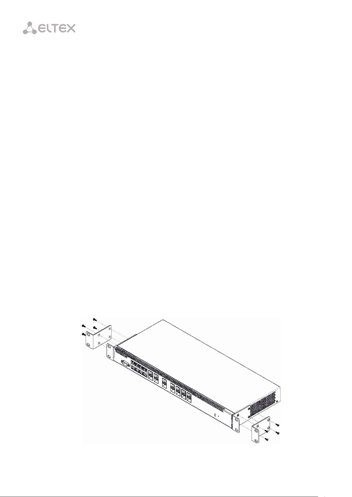
Fig. 7.1 – Support Brackets Mounting
2. PC and measurement instruments should be grounded prior to connection to the terminal. The
potential difference between the terminal case and the cases of the instruments should be less
than 1 V.
3. Prior to turning the terminal on, ensure that all cables are undamaged and securely connected.
4. Make sure the device is off when installing or removing the case.
5. Power modules of LTP-X, LTP-X rev. B should be replaced only when the device is powered off. Follow
the procedure in Section 7.2. Power modules of LTP-X rev. C terminals can be installed and removed
without powering the device off.
6. Follow the instructions given in Chapter 36 to install or remove SFP transceivers. This operation does
not require the terminal to be turned off.
7.2 Terminal Installation
Check the terminal for visible mechanical damage before installing and turning the terminal on. In case of
any damage, stop the installation, fill in a corresponding document, and contact your supplier. If the terminal
was exposed to low temperatures for a long time before installation, leave it for 2 hours at ambient
temperature prior to operation. If the terminal was exposed to high humidity for a long time, leave it for at
least 12 hours in normal conditions prior to turning it on.
Support Brackets Mounting
The delivery package includes support brackets for rack installation and mounting screws to fix the
terminal case on the brackets. To install the support brackets:
Step 1. Align four mounting holes in the support bracket with the corresponding holes in the side panel of
the device.
Step 2. Use a screwdriver to screw the support bracket to the case.
Step 3. Repeat steps 1 and 2 for the second support bracket.
25
Page 26

To avoid overheating and provide necessary ventilation of the terminal, sufficient
space should be provided above and below the terminal, not less than 10 cm.
Fig. 7.2 – Terminal Rack Installation
Terminal Rack Installation
To install the terminal to a rack:
Step 1. Attach the terminal to the vertical guides of the rack.
Step 2. Align mounting holes in the support bracket with the corresponding holes in the rack guides. Use
the holes of the same level on both sides of the guides to ensure the terminal horizontal installation.
Step 3. Use a screwdriver to screw the terminal to the rack.
The terminal is horizontally ventilated. The side panels have air vents. Do not block the air vents to avoid
components overheating and subsequent terminal malfunction.
26
Page 27

Fig. 7.3 – Power Module Installation
Fig. 7.4 – Installation of Power Modules for LTP Rev. C
Power Module Installation
Depending on power supply requirements, the LTP-8X, LTP-4X rev. B, and LTP-8X rev. B terminals can be
supplemented with either an AC power module, 220 V, 50 Hz, or a DC power supply module, 48 V. Location of
the power module is shown in Fig. 7.3.
The LTP-4X rev. C and LTP-8X rev. C terminals can use one or two power modules. Installation of the
second power module is necessary when the device operates under strict reliability requirements. In case of
using two power supply modules, it is allowed to use different power plants for supplying (with different
voltage).
27
Page 28

As for electric parameters, both places for power module installation are identical. In the context of
device operation, the power module located closer to the edge is considered as the main module, and the
one closer to the centre—as the redundant module. Power modules can be installed and removed without
powering the device off. When an additional power module is being installed or removed, the switch
continues operation without restart.
To install a power module:
Step 1. Install the power module into the pocket shown in Fig. 7.3 or Fig. 7.4.
Step 2. Screw the module to the case.
Step 3. Follow the instructions in Section 7.2 to power on.
To install the device:
Step 1. Assemble the device. In case of installation to a 19" form-factor rack, mount the support brackets
from the delivery package to the rack.
Step 2. Ground the case of the device. This should be done prior to connecting the device to power
supply. An insulated multiconductor wire should be used for earthing. The device grounding and the earthing
wire section should comply with the Electric Installation Code. The earth bonding point is located on the rear
panel, see Fig. 6.4, Fig. 6.5, Fig. 6.6.
Step 3. If a PC or another device is supposed to be connected to the switch console port, the device
should be also securely grounded.
Step 4. Connect the power cable to the device.
Step 5. Turn the device on and check the front panel LEDs to make sure the terminal is in normal
operating conditions.
28
Page 29

Part II
Getting Started with the Terminal
29
Page 30

Chapter 8.
Connecting to Terminal CLI
Introduction
This chapter describes various connection methods for Command Line Interface (CLI) of the terminal.
A serial port (hereafter—COM port) is recommended for preliminary adjustment of the terminal.
8.1 Connecting to CLI via COM Port
This type of connection requires PC either to have an integrated COM port or to be supplied with an USBCOM adapter cable. The PC should also have a terminal program installed, e. g. Hyperterminal.
Step 1. Use the null modem cable from the delivery package to connect the console port of the terminal
to the PC COM port as shown in Fig. 8.1.
Fig. 8.1– Connecting the Terminal to a PC via COM Port
Step 2. Launch the terminal program and create a new connection. Select the corresponding COM port in
the Connect to drop-down list. Assign the port settings according to the table below. Click OK.
Speed 115200
Data bits 8
Parity no
Stop bits 1
Stream control N/A
30
Page 31

****************************************
* Optical line terminal LTP-8X _REVC *
****************************************
LTP-8X login: admin
Password: ********
Eltex LTP-8X:rev.C software version 3.26.1 build 1347 on
12.12.2016 14:17
Technical support: http://eltex.nsk.ru/support
Sat Jan 1 09:28:23
LOCAL 2000 LTP-8X#
Step 3. Press Enter. Log into the terminal CLI. Factory settings: login: admin, password: password.
8.2 Connecting to CLI via Telnet Protocol
The Telnet protocol connection is more flexible than the connection via COM port. Connection to CLI can
be established directly at the terminal location or via an IP network with the help of a remote desktop.
This section considers direct connection to CLI at the terminal location. Remote connection is similar, but
requires changes in the terminal IP address that will be considered in detail in Chapter 11.
In order to be connected to the terminal, a PC should have a Network Interface Card (NIC). The
connection will additionally require the sufficient amount of network cable (Patching Cord RJ45) as it is not
included in the delivery package.
Step 1. Connect one end of the network cable to any GE or Combo GE port of the terminal. Connect
another end to NIC on the PC as shown in Fig. 8.2.
Fig. 8.2 – Connecting the Terminal to a PC via Network Cable
Step 2. Assign IP settings for network connections. Set 192.168.1.1 as an IP address and 255.255.255.0 as a
subnet mask.
31
Page 32

Trying 192.168.1.2...
Connected to
192.168.1.2. Escape
character is ’^]’.
**************************************
* Optical line terminal LTP_8X_REVC *
**************************************
LTP-8X login: admin
Password:********
Eltex LTP-8X:rev.C software version 3.26.1 build 1347 on
12.12.2016 14:17
Technical support: http://eltex.nsk.ru/support
Sat Jan 1 21:19:02
LOCAL 2000 LTP-8X#
Fig. 8.3 – Assigning Network Connection Settings
Step 3. On the PC, click Start > Run. Enter telnet and the terminal's IP address. The factory setting for the
IP address is 192.168.1.2. Click OK.
Fig. 8.4 – Running the Telnet Client
Step 4. Log into the terminal CLI. Factory settings: login: admin, password: password.
32
Page 33

login: admin
Password:
********
Eltex LTP-8X:rev.C software version 3.26.1 build 1347 on
12.12.2016 14:17
Technical support: http://eltex.nsk.ru/support
Sat Jan 1 21:44:30
LOCAL 2000 LTP-8X#
8.3 Connecting to CLI via Secure Shell Protocol
Secure Shell connection (SSH) has functionality similar to the Telnet protocol. However, as opposed to
Telnet, Secure Shell encrypts all traffic data, including passwords. This enables secure remote connection via
public IP networks.
This section considers direct connection to CLI at the terminal location. Remote connection is similar, but
requires changes in the terminal IP address that will be considered in detail in Chapter 11.
In order to be connected to the terminal, a PC should have a NIC. The PC should have an SSH client
installed, e. g. PuTTY. The connection will additionally require the sufficient amount of network cable (Patch
Cord RJ-45) as it is not included in the delivery package.
Step 1. Perform steps 1 and 2 from Section 8.2.
Step 2. Run PuTTY. Enter IP address of the terminal. The factory setting for the IP address is 192.168.1.2.
Select port 22 and SSH protocol type. Click Open.
Fig. 8.5 – Running the SSH Client
Step 3. Log into the terminal CLI. Factory settings: login: admin, password: password.
33
Page 34

Chapter 9.
Getting Started with Terminal CLI
Introduction
CLI is the main means of communication between user and the terminal. This chapter considers general
operations in CLI: commands grouping, automatic code completion, and history.
9.1 CLI Views Hierarchy
Views are used in the terminal CLI to group commands and optimize their length.
Fig. 9.1 shows a graphic chart of main views and the commands to switch between them.
Fig. 9.1 – CLI Views Hierarchy
The Top view includes general commands, which refer to the device in general. For instance: view
terminal parameters, firmware update, reboot, etc. The Switch view is a group of switch-related commands:
VLAN, GE interfaces, LACP, etc. The Configure view is a list of terminal configuration commands. For instance:
user management, services configuration, GPON interface and ONT configuration, profile configuration, etc.
34
Page 35

LTP-8X# ex<Tab>
LTP-8X# exit
LTP-8X# co<Tab>
Configure copy
LTP-8X# con<Tab>
LTP-8X#configure
Fig. 9.2 – Switch Views Hierarchy
Fig. 9.3 – Configure Views Hierarchy
Fig. 9.3 shows the Configure view, which consists of four parts. The GPON-port view is used to configure
GPON interfaces. The ONT view is used to configure the ONT. ONT configuration templates are modified in
the ONT template view. The profile of the terminal configuration is configured in the Profile view.
9.2 CLI Automatic Code Completion
In order to make work with CLI faster and easier, an automatic code completion is implemented. A good
knowledge of CLI command system allows user to work with CLI as fast as with graphical interface.
For example, enter the ex command in the Top view and press Tab:
As this view has only one command with the ex prefix, CLI automatically completes it.
If there are several commands with this prefix, CLI shows hints with possible options:
35
Page 36

LTP-8X# show history
Last CLI commands:
show version
configure terminal
exit
show historyLTP-8X#
LTP-8X# <Up>
LTP-8X# show management <Up>
LTP-8X# switch <Up>
LTP-8X# exit <Up>
LTP-8X# show uptime <Up> up 1 day, 23:44
LTP-8X(config)# interface ont 0/0-127
LTP-8X(config)(if-ont-0/0-127)# fec
LTP-8X# show interface ont 0-3 ont online
GPON-port 0 has no online ONTs
GPON-port 1 has no online ONTs
GPON-port 2 has no online ONTs GPON-port 3 has no online ONTs
Total ONT count: 0
9.3 CLI Command History
Sometimes it might be necessary to execute the same set of operations several times. To make the work
with repeating commands easier, the terminal CLI keeps the command history.
The list of previously entered commands can be displayed with the help of the show history command:
Use the Up and Down cursor keys to scroll the command history and the Enter key to execute the
selected command.
9.4 Group Operations
Group operations can be performed on such terminal configuration objects as interfaces and ONT. It is
especially convenient, when you have to apply the same actions to multiple objects.
To perform a group operation, select the range of object IDs instead of one object ID. This feature is
supported by a majority of CLI commands.
For example, enable fec for all ONTs in a certain channel.
Or view the list of active ones in the first 4 GPON channels:
36
Page 37

Part III
Configuring the Terminal
37
Page 38

Chapter 10.
Terminal Configuration
Introduction
A collection of all terminal settings is referred to as configuration. This chapter provides information on
the parts which configuration consists of. It also defines lifecycle of configuration and describes main
operations, which can be performed.
10.1 Configuration Structure
The terminal configuration can be conventionally divided into 3 parts. Fig. 10.1 shows the configuration
structure.
Fig. 10.1 – The Structure of Terminal Configuration
System is a general system part. This group includes such settings as network settings, services
configuration, user table, etc.
Switch represents a switch configuration. This group includes configuration parameters for Ethernet
interfaces of the front panel, as well as VLAN settings.
GPON contains 5 subparts. OLT—settings for GPON OLT and GPON interfaces. OLT profiles—OLT profile
part, which contains profiles for address tables, VLAN, DHCP RA, and PPPoE IA. ONT—ONT configuration
base. ONT templates—ONT template part; ONT profiles—ONT profile part.
38
Page 39

LTP-8X(config)# config autosave hour 3 minute 44
10.2 Configuration Lifecycle
The terminal configuration may have the following states:
—
Running—an active configuration. It refers to the current configuration of the terminal.
—
Candidate—a configuration under review.
—
NVRAM—a configuration stored in non-volatile memory. This configuration will be used as RUNNING
after the device is loaded.
The Running configuration is loaded to a new CLI session and becomes available for review (Candidate).
After changing the configuration (Candidate) in the CLI session, user can either enter the commit command
to accept the changes or use the rollback command to discard the changes and apply the current (Running)
configuration. The save command saves the Running configuration into NVRAM of the terminal.
Fig. 10.2 shows a chart of configuration lifecycle.
Fig. 10.2 – Configuration Lifecycle Chart of the Terminal
10.3 Configuration Autosave
In some cases, for example, when several operators are working on the terminal or the terminal is
automatically configured through OSS/BSS, it may be convenient to organize a centralized saving of the
configuration into NVRAM at a specified time or at a specified time interval. The terminal allows this with the
help of a configuration autosave mechanism.
For daily autosave of the configuration, define a time when autosave should be implemented:
39
Page 40

LTP-8X(config)# config autosave period 3600
LTP-4X(config)# do show config
Config:
Daily autosave: at 22:00
Periodic autosave: every 3600 seconds
LTP-4X(config)#
LTP-4X(config)# no config autosave hour
LTP-4X(config)# no config autosave period
LTP-8X(config)# do commit
LTP-8X# copy fs://config tftp://192.168.1.1/config Upload backup file to TFTP-server..
LTP-8X# configure terminal
LTP-8X(config)# backup uri tftp://192.168.1.1/config
For autosave at specified time intervals, define the interval in seconds:
Check the entered data by using the do show config command.
For disabling a mode, use no command:
Apply the changes.
10.4 Creating a Configuration Backup
Configuration backups allow the terminal operation to be quickly restored after abnormal situations or
replacement. Manual or triggered (on events) creation of backups is recommended at a regular basis.
Terminal configuration is uploaded to a TFTP server which is available in the management network. The
copy command is used to upload the data. Pass the uploaded terminal configuration fs://config and
destination URI as parameters.
Configure a triggered upload to create backups automatically.
Step 1. Go to the configure view and select the URI of the configuration backup.
Step 2. The terminal can be adjusted to upload configuration every time the configuration is saved if
necessary.
40
Page 41

LTP-8X(config)# backup on save
LTP-8X(config)# backup on timer
LTP-8X(config)# backup timer period 3600
LTP-8X(config)# do show backup
Tftp:
Backup on conf save: enabled
Backup on timer: enabled
Backup on timer period: 3600
Backup uri: ’tftp://192.168.1.1/config’
LTP-8X(config)# do commit
LTP-8X# copy tftp://10.0.105.1/config fs://config Download file from TFTP-server..
Reading of the configuration file..
Configuration have been successfully restored (all not saved changes was lost)
LTP-8X# default
Do you really want to set up default configuration? (y/n) y
Configuration have been reseted to default.
Terminal will be reloaded.
Resetting a configuration of a remote terminal also resets network settings. The
terminal will not be available for operation until the network settings are
reconfigured.
Step 3. The terminal can be adjusted to use a timer for configuration upload if necessary. In this case,
additionally set the timer period in seconds.
Step 4. Check the entered data by using the do show backup command.
Step 5. Apply the changes.
10.5 Configuration Restore
The terminal configuration is restored from a TFTP server which is available in the management network.
The copy command is used to restore the data. Define source URI as parameter and fs://config as restored
configuration.
10.6 Configuration Reset
To reset a terminal configuration to factory settings, use the command.
41
Page 42

LTP-8X# show management
Network:
Hostname:
’LTP-8X’
Ipaddr:
192.168.1.2
Netmask:
255.255.255.0
Vlan management:
1
Gateway:
0.0.0.0
Vlan prio:
7
Dscp:
63
LTP-8X# configure terminal
LTP-8X(config)# hostname LTP-8X-1
LTP-8X(config)# management ip 10.0.0.1
LTP-8X(config)# management mask 255.0.0.0
LTP-8X(config)# management gateway 10.0.0.254
Chapter 11.
Network Settings
Introduction
This chapter describes adjustment of network settings for the terminal. Adjusting network settings
enables remote control and integration with OSS/BSS systems.
11.1 Adjustment of Network Settings
It is recommended to adjust network settings via COM port connection. This will prevent issues
with connection loss upstream the terminal being adjusted. Be very careful when using remote
adjustment.
Step 1. Use the show management command to view the current network settings.
Step 2. Switch to the configure view. Set the terminal name by using the hostname command.
Step 3. Set the terminal IP address by using the management ip command.
Step 4. Set the subnet mask by using the management netmask command.
Step 5. Set the default gateway by using the management gateway command.
42
Page 43

LTP-8X(config)# management vid 9
LTP-8X(config)# management cos 5
Proper operation of the inband management function requires VLAN adjustment in
the switch view as described in Chapter 15.
LTP-8X(config)# gpon network mac-age-time 7200
LTP-8X(config)# do commit
Step 6. Set the management VLAN of the terminal by using the management vid command if necessary.
Use management cos to set the P-bit parameter for the management VLAN.
Step 7. Set MAC addresses aging by using the gpon network mac-age-time command.
Pass time in seconds as a parameter.
Step 8. The network settings will change as soon as the configuration is applied. No terminal reboot is
needed.
43
Page 44

Proper operation of the inband management function requires VLAN adjustment in
the switch view as described in Chapter 15.
The factory settings provide only one user, i. e. the device administrator.
login: admin
password: password
When you start to configure the terminal, we recommend you to change the password of
the "admin" user.
LTP-8X# show privileges
Level Privileges
0 !, exit
1 view-ont
2 ont-operation
3 view-ont, ont-operation
4 view-ont, config-ont
ont-operation
5 view-gpon, view-ont
view-ont-profile, ont-operation
Chapter 12.
User Management
Introduction
This chapter is devoted to management of the terminal users.
For security reasons, there is a strictly defined set of permissions, which can be delegated to terminal
users. For these purposes, each user gets his own level of privileges. Level 0 corresponds to a minimum set of
permissions, Level 15—to a maximum set of permissions.
CLI commands are ranked by the level of privileges. Level 0 commands are available to all users. Level 15
commands are available only to Level 15 users. Thus, the level of commands available to a user does not
exceed the user's level.
The levels of privileges can be modified as required.
Step 1. Check the current settings of privileges by using the show privileges command.
44
Page 45

6 view-gpon, view-ont
view-ont-profile, config-gpon
ont-operation, config-ont-profile
7 view-switch, view-gpon
view-ont, view-ont-profile
view-switch-interfaces
8 view-switch, view-gpon
view-ont, view-ont-profile
view-switch-interfaces, config-switch
config-switch-interfaces
9 view-switch, view-gpon
view-ont, view-ont-profile
view-switch-interfaces, config-switch
config-gpon, config-ont
ont-operation, config-ont-profile
config-switch-interfaces
10 view-switch, view-alarm
view-system, view-general
view-gpon, view-ont
view-ont-profile, view-switch-interfaces
11 view-switch, view-alarm
view-system, view-general
view-gpon, view-ont
view-ont-profile, view-switch-interfaces
config-alarm, config-system
config-general
12 view-switch, view-alarm
view-system, view-general
view-gpon, view-ont
view-ont-profile, view-switch-interfaces
config-switch, config-alarm
config-system, config-general
config-switch-interfaces
13 view-gpon, view-ont
view-ont-profile
14 ---
15 view-switch, view-alarm
view-system, view-general
view-gpon, view-ont
view-ont-profile, view-switch-interfaces
config-switch, config-alarm
config-system, config-general
config-gpon, config-ont
ont-operation, config-ont-profile
config-switch-interfaces
LTP-8X# configure terminal
LTP-8X(config)# privilege 1 view-switch
Step 2. Switch to the configure view. Set the required permissions corresponding to the level by using the
privilege command, e. g. set permissions allowing Level 1 to view configuration of the internal switch:
45
Page 46

LTP-8X(config)# do commit
Level
Permissions
0
!, exit
1
view-ont
2
ont-operation
3
view-ont, ont-operation
4
view-ont, config-ont, ont-operation
5
view-gpon, view-ont, view-ont-profile, ont-operation
6
view-gpon, view-ont, view-ont-profile, config-gpon, ont-operation, config-ont-profile
7
view-switch, view-gpon, view-ont, view-ont-profile, view-switch-interfaces
8
view-switch, view-gpon, view-ont, view-ont-profile, view-switch-interfaces, config-switch,
config-switch-interfaces
9
view-switch, view-gpon, view-ont, view-ont-profile, view-switch-interfaces, config-switch,
config-gpon, config-ont, ont-operation, config-ont-profile, config-switch-interfaces
10
view-switch, view-alarm, view-system, view-general, view-gpon, view-ont, view-ont-profile,
view-switch-interfaces,
11
view-switch, view-alarm, view-system, view-general, view-gpon, view-ont, view-ont-profile,
view-switch-interfaces, config-alarm, config-system, config-general
12
view-switch, view-alarm, view-system, view-general, view-gpon, view-ont, view-ont-profile,
view-switch-interfaces, config-switch, config-alarm, config-system, config-general, configswitch-interfaces
13
view-gpon, view-ont, view-ont-profile
14
---
15
view-switch, view-alarm, view-system, view-general, view-gpon, view-ont, view-ont-profile,
view-switch-interfaces, config-switch, config-alarm, config-system, config-general, configgpon, config-ont, ont-operation, config-ont-profileconfig-switch-interfaces
LTP-8X(config)# do show users config
## Name Privilege
1 root 15
2 admin 15
3 remote 15
Step 3. Settings of privileges will be applied immediately. No terminal reboot is needed.
The list of operations and the default levels are shown in Table 12.1.
Table 12.1 – Permissions and the Required Level of Privileges
12.1 User List Preview
To view the list of terminal users, enter the show users command:
The admin and root users always exist and cannot be deleted or duplicated. The terminal supports up to
16 users.
46
Page 47

LTP-8X(config)# user operator
LTP-8X(config)# do show users config
## Name Privilege
1 root 15
2 admin 15
3 remote 15
4 operator 0
LTP-8X(config)#
LTP-8X(config)# user operator password newpassword
LTP-8X(config)# user operator
LTP-8X(config)# do show users config
## Name Privilege
1 root 15
2 admin 15
3 remote 15
4 operator 0
LTP-8X(config)#
LTP-8X(config)# user operator priviledge 15
LTP-8X(config)# do show users config
## Name Privilege
1 root 15
2 admin 15
3 remote 15
4 operator 15
LTP-8X(config)#
12.2 Adding a New User
In order to operate effectively and safely, the terminal, as a rule, requires one or several additional users.
To add a new user, enter the user command in the configure view:
Pass the name of the new user as a parameter to the user command. The name should not be longer
than 32 characters. The name should not contain special characters.
12.3 Changing User Password
To change user password, enter the user command. Pass the user name and a new password as
parameters.
The password should not be longer than 31 characters and shorter than 8 characters. If the password
contains a space, use quotations for the password.
12.4 Viewing and Changing User Access Rights
To manage user access rights, a user priority system is implemented. A newly created user is granted with
a minimal set of permissions:
To change the user priority level, enter the user command. Pass the user name and a new priority as
parameters.
47
Page 48

LTP-8X# configure terminal
LTP-8X(config)# no user operator
12.5 Deleting a User
To delete a user, enter the no user command in the configure view. Pass the user name as a parameter:
48
Page 49

Hereafter, the term "authorization" means authorization of the commands - definning
rights for executing commands on a remote server.
Authorization of a user – a process of obtaining a specified permission set, combined with
authentication process.
Protocol
Function
Tacacs+
Radius
Authentication
+
+
Authorization
+
-
Accounting start-stop
+
+
Accounting commands
+
-
LTP-8X# configure terminal
LTP-8X(config)# radius-server host 10.10.10.1 proirity 0
LTP-8X(config)# radius-server host 10.10.10.2 proirity 1
LTP-8X(config)# radius-server host 10.10.10.3 proirity 2
LTP-8X(config)# tacacs-server host 10.10.10.4
LTP-8X(config)# radius-server key 12345678-r0
LTP-8X(config)# radius-server key 12345678-r1 priority 1
Chapter 13.
ААА configuration
Introduction
This chapter describes configuring of services and protocols related to authentication, authorization and
accounting.
LTP-X supports radius and tacacs+ AAA protocols. Table 13.1 represents functionalities of the protocols.
Table 13.1 – Privileges and required access level for users
13.1 Configuring servers
The principles of servers configuration are common for supported protocols. You can configure an IP
address, key, response timeout and a data exchange port for each server. You can set up to 3 servers for the
RADIUS. The LTP will apply to the servers according to their priorities. If the priority is not set, the 0 priority
(the highest) will be used by default.
Step 1. Configure IP address of radius/tacacs+ server.
Step 2. Define an encryption key used while data exchange with the server.
49
Page 50

LTP-8X(config)# radius-server key 12345678-r2 priority 2
LTP-8X(config)# tacacs-server key 12345678
LTP-8X(config)# radius-server timeout 3
LTP-8X(config)# radius-server timeout 3 priority 1
LTP-8X(config)# radius-server timeout 3 priority 2
LTP-8X(config)# tacacs-server timeout 3
LTP-8X(config)# radius-server port 50005
LTP-8X(config)# radius-server port 50006 priority 1
LTP-8X(config)# radius-server port 50007 priority 2
LTP-8X(config)# tacacs-server port 50008
LTP-8X(config)# do commit
LTP-8X# configure terminal
LTP-8X(config)# aaa authentication radius
LTP-8X# configure terminal
LTP-8X(config)# aaa authorization tacacs+
LTP-8X# configure terminal
LTP-8X(config)# aaa accounting start-stop radius
LTP-8X# configure terminal
LTP-8X(config)# aaa accounting commands tacacs+
LTP-8X(config)# do commit
Step 3. Define server response timeout.
Step 4. Define a port for data exchange with the server (if necessary).
Step 5. Apply the changes.
13.2 ААА methods configuration
By default, every AAA function is implemented locally - local user data base is used for authentication and
authorization, accounting via a remote server is disabled.
For using of configured in previous steps servers, define a method of a function performing.
Step 1. Select an authentication method:
Step 2. Select an authorization method:
Step 3. Select a CLI session start/stop accounting method:
Step 4. Select a method of commands accounting:
Step 5. Apply the changes:
In order to disable a function, use no command:
50
Page 51

LTP-8X# configure terminal
LTP-8X(config)# no aaa accounting commands
In case server configured for a function unavailable or key is not defined properly, the
function will be implemented locally.
LTP-8X# configure terminal
LTP-8X(config)# ip snmp enable
LTP-8X(config)# ip snmp access-control
LTP-8X(config)# ip snmp allow ip 192.168.1.13
Chapter 14.
Services Configuration
Introduction
This chapter describes configuration of integrated terminal services.
14.1 SNMPD Configuration
To work with the Eltex.EMS management system, the terminal should be configured to work with Simple
Network Management Protocol (SNMP).
Step 1. Switch to the configure view.
Step 2. Enable the SNMP agent of the terminal by using snmp enable command.
Step 3. Enable ACL check by using snmp access-control command if necessary. Add the record into the
whitelist by using snmp allow command. Pass the IP address of the host which will be used to connect to the
SNMP agent, as a parameter.
51
Page 52

It is possible to configure several receivers of SNMP traps of the same version.
LTP-8X(config)# ip snmp traps 192.168.1.13 type v2
LTP-8X(config)# ip snmp traps 192.168.1.113 type v1
LTP-8X(config)# do show ip snmp
Snmp:
Enabled: true
Access control: false
Allow ip: <list is empty>
Traps [0]:
Type: v2
Ipaddr: 192.168.1.13
Traps [1]:
Type: v1
Ipaddr: 192.168.1.113
Version: v2
Communityro: 'public'
Communityrw: 'private'
Trap community: 'public'
Location: 'admin'
Contact: 'admin'
Alias: <for showing use separate command>
EngineID: 0x6C2A20B42CB28232FABEA8EE19
Users: <for showing use separate command>
LTP-8X(config)#
LTP-8X(config)# do commit
The types and purpose of SNMP traps are closely connected with the log of active alarms.
LTP-8X(config)# ip snmp version v3
Step 4. Configure SNMP trap replication to allow the management system to receive the traps. For
example, add 2 replicators and specify to send v2 SNMP traps to 192.168.1.13 and v1 traps to 192.168.1.113.
To do this, use the ip snmp traps command.
Step 5. Check the entered data by using the show ip snmp command:
Step 6. The settings of the SNMP agent change as soon as the configuration is applied.
No terminal reboot is needed.
You need to configure users to operate with SNMPv3.
Step 1. Set the version of SNMP agent to 3:
Step 2. Add users and set the privilege levels
52
Page 53

LTP-8X(config)# ip snmp user "rwuser" auth-password "rwpass" enc-password "rwencr" access rw
LTP-8X(config)# ip snmp user "rouser" auth-password "ropass" enc-password "roencr" access ro
LTP-8X(config)# LTP-8X(config)# do show ip snmp users
SNMP users
~~~~~~~~~~
User name permissions
-------------------- --------------rwuser read-write
rouser read-only
2 SNMP users.
LTP-8X(config)#
The SNMPv3 agent supports authNoPriv and authPriv methods.
The encryption of the password performs according to the MD5 algorithm.
LTP-8X# configure terminal
LTP-8X(config)# ip ntp enable
LTP-8X(config)# ip ntp ip 192.168.1.254
LTP-8X(config)# ip ntp interval 3600
LTP-8X(config)# ip ntp timezone 7
LTP-8X(config)# ip ntp daylightsaving
Step 3. Check the configuration
14.2 NTPD Configuration
The terminal has no integrated real-time clocks with a battery. For the events in system log to show
correct time and for automated operations to be performed in time, time synchronisation should be adjusted
with the help of the NTP protocol.
Step 1. Switch to the configure view.
Step 2. Enable time synchronisation by using the ip ntp enable command. Specify the IP address to be
used for synchronisation in the ip ntp ip command.
Step 3. Specify the synchronisation interval in seconds by using the ntp interval command.
Step 4. Use the ip ntp timezone and ip ntp daylightsaving commands to set the time zone of your region
and indicate whether it should be switched to the daylight-saving time.
53
Page 54

LTP-8X(config)# do show ip ntp
Ntp:
Enabled: true
Ntpserver: 192.168.1.254
Interval: 3600
Timezone: 7
Daylightsaving: true
LTP-8X(config)#
LTP-8X(config)# do commit
LTP-8X# configure terminal
LTP-8X(config)# ip acs server enable
LTP-8X(config)# ip acs server ip 192.168.200.9
LTP-8X(config)# ip acs server mask 255.255.255.0
LTP-8X(config)# ip acs server vid 200
LTP-8X(config)# ip acs server scheme http
1
Step 5. Check the entered data by using the do show ip ntp command.
Step 6. Apply the configuration by using the commit command.
14.3 ACSD and DHCPD Configuration
The terminal has an integrated auto configuration server (ACS)1. To ensure interaction between ONTs and
ACS, ONTs should obtain IP addresses for their management interfaces. The terminal has an integrated DHCP
server to solve this task. These two servers are interconnected and cannot work separately.
14.3.1 ACSD Configuration
Step 1. Switch to the configure view.
Step 2. Turn on the ACS server by using the ip acs server enable command.
Step 3. If necessary, set the IP address, server mask, and identifier of the management VLAN, which will
be used to send packets between ACS and ONTs. By default, mask 21 is set, which enables 2,046 hosts per
network.
Step 4. In addition to HTTP, ACS can also use an extended version of this protocol that supports
encryption—HTTPS. This is configured by the ip acs server scheme command:
Step 5. If necessary, configure the login and password to be used by ONTs to access the ACS server:
This is actual for LTP-4/8X rev. B and LTP-4/8X rev. C only.
54
Page 55

LTP-8X(config)# ip acs server login acs
LTP-8X(config)# ip acs server password acsacs
LTP-8X(config)# ip dhcp server enable
LTP-8X(config)# ip dhcp server range 192.168.200.10 192.168.200.150
LTP-8X(config)# ip dhcp server lease-time
LTP-8X(config)# ip dhcp server option-43
LTP-8X(config)# do show ip acs server
ACS server:
Enabled: true
Ip: 192.168.200.9
Port: 9595
Mask: 255.255.255.0
Vid: 200
Scheme: 'http'
Login: 'acs'
Password: 'acsacs'
External fw ip: 0.0.0.0
External fw port: 9595
Local fw port: 9696
ACS DHCP server:
Enabled: true
Max lease time: 600
Insert option 43: true
First IP: 192.168.200.10
Last IP: 192.168.200.150
DHCP option 43 (will be generated automatically):
URL: 'http://192.168.200.9:9595'
Login: 'acs'
Password: 'acsacs'
LTP-8X(config)# do commit
14.3.2 DHCPD Configuration
Step 1. Start the DHCP server by using the ip dhcp server enable command.
Step 2. Configure the range of IP addresses to be assigned by the server with the ip dhcp server range
command and specify the first and the last addresses of the range:
Step 3. Set the maximum lease time, during which the server allows clients to use the addresses, with the
ip dhcp server lease-time command:
Step 4. Use the ip dhcp server option-43 command to configure output of option 43 in the DHCP offer
packet for correct connection of ONTs to the ACS server. View general settings of ACSD and DHCPD to check
the format of the option.
Step 5. Check the changes by using the do show ip acs server command.
Step 6. Apply the configuration by using the commit command.
55
Page 56

Module
Description
alarm
Alarms log messages
snmp
Messages from the SNMP agent
dhcpd
Messages from the integrated DHCP server
pmchal-ipc
Messages from the pmchal subsystem of interprocess communication
pmchal-gpon
GPON messages
pmchal-machine
Messages on operation of state machines for OLT, channels, and ONT
pmchal-olt
OLT general information
pmchal-gpon-port
Information about GPON channels
pmchal-ont
ONT information
pmchal-scheduler
Messages from the scheduler subsystem
pmchal-rdn
Messages on GPON channels reservation
pmchal-dhcpra
Messages from DHCP Relay Agent
pmchal-pppoeia
Messages from PPPoE Intermediate Agent
14.4 LOGD Configuration
System log collects terminal history data and allows its further display. Adjustment of system log operates
with such terms as module, filter level, and output device.
Fig. 14.1 – Terminal System Log
Messages of the system log are grouped into modules according to their functions. Configuration of the
following modules is possible:
Table 14.1 – System Log Modules
A filtration level and additional display information can be specified for messages of each module.
The filtration level sets the minimum importance level of the messages to be displayed in the log.
The used filtration levels are listed in Table 14.2.
56
Page 57

Level
Description
emergency
Further operation of the system is not possible
alert
The system requires emergency intervention
critical
Critical events
error
Operation errors
warning
Warnings
notice
Important events during normal operation
info
Information messages
debug
Debug messages
none
Messages are not registered in the log
The emergency level is the maximum level, the debug level is the minimum one.
Output Device
Name
Description
System log
system
The system log allows the log to be displayed locally or with the
help of the syslog server.
Console
console
Being used for log display, the console allows system messages to
be visible as soon as they are received in the terminal connected
to the Console port.
CLI sessions
rsh
Being used for log display, CLI sessions allow system messages to
be visible as soon as they are received in all CLI sessions
connected via telnel or SSH.
File
file
Logging into a file allows system messages to be written directly
to the file, which can be sent to support specialists for further
analysis.
LTP-8X(config)# logging module pmchal-gpon loglevel info
Table 14.2 – System Log Filtration Levels
The log subsystem allows display of the terminal operation log on different devices. All output devices
can be used simultaneously.
Table 14.3 – System Log Output Devices
The log is saved in non-volatile memory by default. The system has 4 log rotated files of 1M each. The
last 3 logs are archived to gzip.
14.4.1 Modules Configuration
Consider module configuration by the example of the pmchal-gpon module responsible for messages
from the GPON subsystem. Other modules have similar configuration process.
Step 1. Set the logging level with the help of the logging module pmchal-gpon loglevel command.
57
Page 58

LTP-8X(config)# do show logging module pmchal-gpon
Log:
Submodule [pmchal-gpon]:
Log level: notice
LTP-8X(config)#
LTP-8X(config)# do commit
LTP-8X(config)# logging commands
LTP-8X(config)# logging permanent
LTP-8X(config)# logging buffer 262144
LTP-8X(config)# logging remote 192.168.1.43
Every output device may have its own filtration level or have the output disabled.
Step 2. To view information about modules, use the do show logging module pmchal-gpon command.
Step 3. Apply the configuration by using the commit command.
14.4.2 Configuring of command logging to syslog
The system is capable to record all the user's commands to syslog. Use the following command to
activate the function:
14.4.3 Configuring the log storage
Use the following command to record logs to non-volatile memory:
If you enter «no» before the command, the logs will be recorded to RAM. In this case, the logs will be
erased after reboot.
14.4.4 System Log Configuration
Step 1. Use the logging buffer command to specify the memory size in bytes to be used for system log
storage.
Step 2. If necessary, use the logging remote command to specify the IP address of the remote SYSLOG
server to be used to display system log.
Step 3. Configure the output devices by using the logging command.
For example, change the display level for the CLI sessions, which are not connected via the RS-232
console port, to "info" and disable output to file:
58
Page 59

LTP-8X(config)# logging rsh loglevel info
LTP-8X(config)# logging file loglevel none
LTP-8X(config)# do show logging settings
Log:
Remote syslog: 192.168.1.43
Port: 514
Size: 16384
Save logs between boots: true
Log input commands: false
Destinations:
System: notice
Console: notice
Remote shells: info
File: none
TP-8X#
LTP-8X(config)# do commit
Event
Description
Threshold
ram
Free RAM size decreased to the threshold
30% *
login
User tried to log in or logged in using their
credentials
-
config_save
User saved the configuration
-
firmware_update
LTP-8X firmware update completed
successfully / with errors
-
duplicate_mac
Two devices with the same MAC addresses
detected
physical_layer_flapping
Flapping on Ethernet ports
-
pon-gpon_port_no_ont
The first ONT connected / the last ONT
disconnected on channel
ont_physical_layer
ONT connected/disconnected
-
olt_update
OLT chip firmware update completed
successfully / with errors
-
ont_update
ONT chip firmware update completed
successfully / with errors
gpon-port_flapping
GPON interface flapping
-
Step 4. To view SYSLOG configuration, use the do show logging settings command.
Step 5. Apply the configuration by using the commit command.
14.5 ALARMD Configuration
ALARMD is a terminal alarms manager. Alarms manager enables troubleshooting and provides
information about important events related to terminal operation.
A record in active alarms log (an event) corresponds to an event, which happened in the terminal. Types
of events and their descriptions are provided in Table 14.4.
Table 14.4 – Types of Events in the Active Alarms Log
59
Page 60

ont_flapping
ONT flapping
-
download
File download completed successfully / with
errors
-
battery_power
Switch ONT to battery power
-
battery_low
ONT battery low
Set in ONT
lan_los
ONT Ethernet port lost connection
-
ont_config
Configuration of the connected ONT
valid/invalid
file_delete
File deleted successfully / with errors
-
physical_layer_errors
Physical layer errors on Ethernet ports
-
physical_layer_block
Ethernet port blocked
-
link
Ethernet port status changed (up/down)
-
logout
User logged out
ont_dying_gasp
Dying Gasp signal received from ONT
-
ont_rei
Remote Error Indication (REI)
ont_power_off
ONT power off
-
config_change
OLT configuration changed
shutdown
SNMP agent shut down
-
oms
OMS-MIB operation completed successfully /
with errors
ont_state_changed
ONT status changed
-
ont_config_changed
ONT configuration changed
-
gpon_port_state_changed
OLT channel configuration changed
-
pon_alarm_gpon_port
Event related to OLT channel
-
pon_alarm_onui
Event related to ONT
-
ont_update_inprogress
Updating ONT firmware
-
olt_device_reset
Resetting OLT chip
-
ont_signal_degrade
The signal received from OLT is below the
threshold value
–28 dBm
ont_high_rx_power
The signal received from ONT is above the
threshold value
–8 dBm
ont_low_rx_power
The signal received from ONT is below the
threshold value
gpon-port-ont-count-overflow
ONT number on channel exceeded
olt_device_not_working
GPON OLT configuration was loaded
successfully / with errors
-
60
Page 61

load_average
Average CPU load reached the threshold,
estimated time is 1 minute
120*
free_space
Free drive space decreased to the threshold
30%*
temperature
Temperature of one of the two OLT chips
exceeded the threshold
60
redundancy_switch
Switching to redundant channel
-
redundancy_fail
Emergency switching to redundant channel
-
fan
Fan rotation speed exceeded the safe
operating limits
4,800 < X
< 9,000*
system_reboot
System reboot alarm message
rssi-update
RSSI value on ONT changed
-
storm-detected
The excess of the limit of broadcast/multicast
/unknown unicast traffic transmission
Power-supply
The status of the power supplies modules has
been changed
-
Token
Description
severity
Describes event severity. Has four statuses
(info, minor, major, critical)
send-on-in
Specifies whether an SNMP trap should be sent when an event is added to
the log. Has two states (true/false)
send-on-out
Specifies whether an SNMP trap should be sent when an event is deleted
from the log. Has two states (true/false)
ttl
The time an event exists in the active alarms log (from 1 to 2,147,483,647).
Specified in seconds. The parameter has several special values. 0—the
event exists in the log until a normalising event is received. –1—an SNMP
trap is sent (if specified), but the event is not recorded in the alarms log.
LTP-8X# configure
* The value can be adjusted.
Every record in the active alarms log has the parameters specified in Table 14.5 that are specified for
every event type.
Table 14.5 – Parameters of Events in the Active Alarms Log
14.5.1 Active Alarms Log Configuration
Step 1. To configure the active alarms log, switch to the configure view.
Step 2. Use the alarm command to specify the necessary event parameters. Event types are listed in Table
14.4, the parameters and possible values are given in Table 14.5.
61
Page 62

LTP-8X(config)# alarm temperature severity critical
LTP-8X(config)# alarm temperature in
LTP-8X(config)# alarm temperature out
LTP-8X(config)# alarm temperature ttl 0
LTP-8X(config)# do commit
Step 3. Apply the changes by using the do commit command.
62
Page 63

LTP-8X# switch
LTP-8X(switch)# configure
LTP-8X(switch)(config)#
LTP-8X(switch)(config)# vlan 5
LTP-8X(switch)(config-vlan)#
CLI automatically switches views to work with the VLAN. The same command is used to
configure existing VLANs.
LTP-8X(switch)(config-vlan)# tagged pon-port 0 – 1
Chapter 15.
VLAN Configuration
Introduction
This chapter describes VLAN configuration in the terminal switch.
VLAN (Virtual Local Area Network) is a group of devices, which communicate on the channel level and are
combined into a virtual network, connected to one or more network devices (GPON terminals or switches).
VLAN is a very important tool for creating a flexible and configurable logical network topology over the
physical topology of a GPON network. VLAN has two or more switch interfaces. A VLAN member interface can
be either tagged or untagged. An outgoing packet of a tagged interface has a VLAN tag. An outgoing packet of
an untagged interface has no VLAN tags.
15.1 Adding a VLAN
Step 1. VLAN is configured in the terminal switch. Execute the switch and configure commands
consecutively to switch to the config view.
Step 2. Add a VLAN by using the vlan command. Pass VID as a parameter.
15.2 VLAN Configuration
Step 1. Add tagged interfaces with the help of the tagged command. Pass interface type and number (or a
range) as parameters. The interface types and numbers are given in Table 16.1, Chapter 16.
63
Page 64

LTP-8X(switch)(config-vlan)# untagged front-port 1
LTP-8X(switch)(config-vlan)# forbidden 10G-front-port 0 – 1
LTP-8X(switch)(config-vlan)# forbidden front-port 0 , front-port 2 , front-port 3
LTP-8X(switch)(config-vlan)# no ip igmp snooping enable
LTP-8X(switch)(config-vlan)# ip igmp snooping querier enable
LTP-8X(switch)(config-vlan)# ip igmp snooping querier fast-leave
LTP-8X(switch)(config-vlan)# ip igmp snooping querier user-prio 4
LTP-8X(switch)(config-vlan)# ip igmp snooping querier dscp 40
LTP-8X(switch)(config-vlan)# ip igmp version v2-v3
LTP-8X(switch)(config-vlan)# ip igmp query-interval 125
LTP-8X(switch)(config-vlan)# ip igmp query-response-interval 10
LTP-8X(switch)(config-vlan)# ip igmp last-member-query-interval 1
LTP-8X(switch)(config-vlan)# ip igmp robustness 2
Step 2. Add untagged interfaces by using the untagged command if needed. Pass interface type and
number (or a range) as parameters.
Step 3. Delete all unnecessary interfaces from the VLAN with the help of the forbidden command. Pass
interface type and number (or a range) as parameters.
Step 4. Disable IGMP snooping by using the no ip igmp snooping enable command if needed.
Step 5. Configure the IGMP querier if needed. It can be enabled with the help of the ip igmp snooping
querier enable command.
The fast-leave mode is enabled by means of the ip igmp snooping querier fast-leave command. By
default, this mode is disabled.
DSCP and 802.1P marking for IGMP query is configured by means of the ip igmp snooping querier user-
prio and ip igmp snooping querier dscp commands.
Step 6. Configure IGMP if needed.
Compatible versions (v1, v2, v3, or their combination):
Interval between queries:
Maximum query response time:
Interval between Group-Specific Queries:
Robustness:
Step 7. Disable MLD snooping by using the no ipv6 mld snooping enable command if needed.
64
Page 65

LTP-8X(switch)(config-vlan)# no ipv6 mld snooping enable
LTP-8X(switch)(config-vlan)# ipv6 mld snooping querier enable
LTP-8X(switch)(config-vlan)# ipv6 mld snooping querier fast-leave
LTP-8X(switch)(config-vlan)# ipv6 mld snooping querier user-prio 4
LTP-8X(switch)(config-vlan)# ipv6 mld snooping querier dscp 40
LTP-8X(switch)(config-vlan)# ipv6 mld version v1-v2
LTP-8X(switch)(config-vlan)# ipv6 mld query-interval 125
LTP-8X(switch)(config-vlan)# ipv6 mld query-response-interval 10
LTP-8X(switch)(config-vlan)# ipv6 mld last-member-query-interval 1
LTP-8X(switch)(config-vlan)# ipv6 mld robustness 2
LTP-8X(switch)(config-vlan)# name iptv
LTP-8X(switch)(config-vlan)# exit
LTP-8X(switch)(config)# commit
LTP-8X(switch)(config)# no vlan 5
Step 8. Configure the MLD querier if needed. It can be enabled with the help of the ipv6 mld snooping
querier enable command.
The fast-leave mode is enabled by means of the ipv6 mld snooping querier fast-leave command. By
default, this mode is disabled.
DSCP and 802.1P marking for MLD query is configured by means of the ipv6 mld snooping querier user-
prio and ipv6 mld snooping querier dscp commands.
Step 9. Configure MLD if needed.
Compatible versions (v1, v2):
Interval between queries:
Maximum query response time:
Interval between Group-Specific Queries:
Robustness:
Step 10. For further convenience, specify a VLAN name by using the name command. To clear the name,
use the no name command. The default name is VID.
Step 11. Apply the configuration by using the commit command.
15.3 Deleting a VLAN
Step 1. Delete a VLAN by using the no vlan command. Pass VID (or its range) as a parameter.
65
Page 66

Criterion
Mask
Example of a command
Src MAC
yes
permit A8:F9:4B:00:00:00 FF:FF:FF:00:00:00 any
Dst MAC
yes
permit any A8:F9:4B:00:00:00 FF:FF:FF:00:00:00
Vlan
no
permit any any vlan 10
COS
yes
permit any any vlan any cos 4 4
Ethertype
yes
Permit any any vlan any cos any ethertype 0x0800 0xFF00
LTP-8X# switch
LTP-8X(switch)# configure
LTP-8X(switch)(config)# mac access-list extended eltexsrc
LTP-8X(switch)(config-mac-al)# deny A8:f9:4B:00:AA:00 FF:FF:FF:FF:FF:00 any
LTP-8X(switch)(config-mac-al)# deny any any vlan any cos 7 7
LTP-8X(switch)(config-mac-al)# permit A8:F9:4B:00:00:00 FF:FF:FF:00:00:00 any vlan 2 cos 4 4
LTP-8X(switch)(config-mac-al)# exit
LTP-8X(switch)(config)# interface front-port 7
LTP-8X(switch)(config-if)# service-acl mac eltexsrc
LTP-8X(switch)(config-if)# exit
LTP-8X(switch)(config)# commit
LTP-8X(switch)# show access-list
Extended MAC access list "eltexsrc"(#0), filters count: 3
Rule 1 (deny):
MAC SA A8:F9:4B:00:AA:00 [FF:FF:FF:FF:FF:00]
Rule 2 (deny):
COS 7 [7]
Rule 3 (permit):
Chapter 16.
Configuring Access Control List and policy
Introduction
ACL (Access Control List) – the table which defined filtering rules for incoming traffic according to data
transmitted in the incoming packets: protocols, TCP/UDP ports, IP address or MAC address. The ACL based on
IPv4 and MAC should have different names. You can set one type of the lists per interface. Each access list
contains up to 20 rules.
16.1 Configuring MAC Access List
In a MAC access list, filtering is implemented according to the following criteria and a mask:
Table 16.1 – The list of MAC access list criteria
Step 1. Create a mac access-list
Step 2. Configure rules and assign the list to a port
Step 3. Check the list configuration
66
Page 67

MAC SA A8:F9:4B:00:00:00 [FF:FF:FF:00:00:00]
Vlan 2
COS 4 [4]
LTP-8X(switch)# show interfaces acl front-port 7
Interface MAC access-list IP access-list
front-port 0 eltexsrc -
Criterion
Mask
Example of a command
Proto ID
no
permit tcp ...
permit udp ...
permit any ...
permit proto <id> ...
Src IP
yes
permit any 10.10.0.0 255.0.255.0 any
Dst IP
yes
permit any any 10.10.0.0 255.0.255.0
DSCP
no
permit any any any dscp 48
Precedence
no
permit any any any precedence 7
Src MAC
yes
permit any any any dscp any mac A8:F9:4B:00:00:00
FF:FF:FF:00:00:00 any
Dst MAC
yes
permit any any any dscp any mac any A8:F9:4B:00:00:00
FF:FF:FF:00:00:00
Vlan
no
permit any any any dscp any mac any any vlan 10
COS
yes
permit any any any dscp any mac any any vlan any cos 4 4
Ethertype
yes
permit any any any dscp any mac any any vlan any cos any
ethertype 0x0800 0xFF00
LTP-8X# switch
LTP-8X(switch)# configure
LTP-8X(switch)(config)# ip access-list extended filter5
LTP-8X(switch)(config-ip-al)# deny tcp 10.10.5.0 255.255.255.0 any any any
LTP-8X(switch)(config-ip-al)# permit tcp 10.10.0.0 255.255.0.0 any any any
LTP-8X(switch)(config-ip-al)# exit
LTP-8X(switch)(config)# interface front-port 7
LTP-8X(switch)(config-if)# service-acl ip filter5
LTP-8X(switch)(config-if)# exit
LTP-8X(switch)(config)# commit
LTP-8X(switch)# show access-list
Extended IP access list "filter5"(#10), filters count: 2
Rule 1 (deny):
IPv4 protocol 6 (TCP)
IP SA 10.10.5.0 [255.255.255.0]
Sport 8080
Step 4. Check the list assignment to the port
16.2 Configuring IP Access List
The rules of an IP access list support criteria that are available in a MAC access list.
Table 16.2 – The list of the IP access list criteria
Step 1. Create an ip access-list
Step 2. Configure rules and assign the list to a port
Step 3. Check the list configuration
67
Page 68

Rule 2 (permit):
IPv4 protocol 6 (TCP)
IP SA 10.10.0.0 [255.255.0.0]
LTP-8X(switch)# show interfaces acl front-port 7
Interface MAC access-list IP access-list
front-port 0 eltexsrc filter5
offset-list list1 <offset-type> <offset> <byte-mask> <byte-value> ...
List
Type
Limits
mac
l2
0..127
mac
dst-mac
0..5
mac
src-mac
0..5
mac
inner-tag
0..1
mac
outer-tag
0..1
mac
ethtype
0..1
ip
l3
0..23
ip
l4
0..89
permit any any vlan any cos any ethertype any offset-list eltex1p
LTP-8X# switch
LTP-8X(switch)# configure
LTP-8X(switch)(config)# ip access-list extended EltexOUI
LTP-8X(switch)(config-mac-al)# offset-list e1 l2 0 FF A8 l2 1 FF F9 l2 2 FF 4B
LTP-8X(switch)(config-mac-al)# offset-list e2 l2 0 FF E0 l2 1 FF D9 l2 2 FF E3
LTP-8X(switch)(config-mac-al)# permit any any vlan any cos any ethertype any offset-list e1
LTP-8X(switch)(config-mac-al)# permit any any vlan any cos any ethertype any offset-list e2
LTP-8X(switch)(config-mac-al)# exit
LTP-8X(switch)(config)# interface pon-port 0
LTP-8X(switch)(config-if)# service-acl mac OUIfilter
LTP-8X(switch)(config-if)# exit
LTP-8X(switch)(config)# commit
Step 4. Check the list assignment to the port
16.3 Configuring ACL based on a bit mask
The filtering based on a bit mask is available in MAC and IP access lists. The configuration is
implemented with the help of offset lists.
Command format:
You can configure up to 5 unique offsets on the OLT.
Table 16.3 – The list of the available offsets
Step 1. Create an access-list
Step 2. Configure rules and assign the list to a port
68
Page 69

LTP-8X(switch)# show access-list
Extended MAC access list "EltexOUI"(#2), filters count: 2
Offset lists:
e1 l2:0:FF:A8 l2:1:FF:F9 l2:2:FF:4B
e2 l2:0:FF:E0 l2:1:FF:D9 l2:2:FF:E3
Rule 1 (permit):
Offset-list e1
Rule 2 (permit):
Offset-list e2
LTP-8X# switch
LTP-8X(switch)# configure
LTP-8X(switch)(config)# ip access-list extended sip-dhcp-acl
LTP-8X(switch)(config-ip-al)# permit udp any 68 any 67
LTP-8X(switch)(config-ip-al)# permit udp any any any 5060
LTP-8X(switch)(config-ip-al)# exit
LTP-8X(switch)(config)# class-map sip-dhcp-class
LTP-8X(switch)(config-class 'sip-dhcp-class')# match access-group sip-dhcp-acl
LTP-8X(switch)(config-class 'sip-dhcp-class')# exit
LTP-8X(switch)(config)# policy-map cos7
LTP-8X(switch)(policy-class 'cos7')# class sip-dhcp-class
LTP-8X(switch)(traffic-class 'sip-dhcp-class')# cos 7
LTP-8X(switch)(traffic-class 'sip-dhcp-class')# exit
LTP-8X(switch)(policy-class 'cos7')# exit
LTP-8X(switch)(config)# interface pon-port 0
LTP-8X(switch)(config-if)# service-policy cos7
LTP-8X(switch)(config-if)# exit
LTP-8X(switch)(config)# commit
LTP-8X(switch)# show access-list
Extended IP access list "sip-dhcp-acl"(#8), filters count: 2
Rule 1 (permit):
IPv4 protocol 17 (UDP)
Sport 68
Dport 67
Rule 2 (permit):
IPv4 protocol 17 (UDP)
Dport 5060
LTP-8X(switch)# show interfaces acl pon-port 0
Interface MAC access-list IP access-list Policy-map
pon-port 0 - - cos7
Step 3. Check the list configuration
16.4 Configuring policy
Configuring policy allows you to perform various manipulations on classified traffic, such as cos, dscp,
queue setting.
Step 1. Create an access-list according to which the traffic will be classified.
Step 2. Create a traffic class
Step 3. Set policy
Step 4. Check the configuration of the policy and classes
While the configuration, you should remember that deny in an ACL rule exclude the traffic from
processing according to policy.
69
Page 70

LTP-8X# switch
LTP-8X(switch)# configure
LTP-8X(switch)(config)#
LTP-8X(switch)(config)# ip igmp snooping
TP-8X(switch)(config)# ipv6 mld snooping
Snooping is globally enabled in all VLANs.
MLD snooping is not supported for Model 1.
Chapter 17.
IGMP and MLD Configuration in Terminal
Switch
Introduction
This chapter describes IGMP and MLD configuration in the terminal switch.
17.1 Enabling Snooping
Step 1. Snooping is configured globally in the terminal switch. Execute the switch and configure
commands consecutively to switch to the config view.
Step 2. Enable IGMP snooping by using the ip igmp snooping command.
Step 3. Enable MLD snooping by using the ip igmp snooping command.
70
Page 71

LTP-8X(switch)(config)# ip igmp proxy report enable
LTP-8X(switch)(config)# ip igmp proxy report range 224.0.0.0 239.255.255.255 from 200 to 98
LTP-8X(switch)(config)# ipv6 mld proxy report enable
LTP-8X(switch)(config)# ipv6 mld proxy report range ff15:0::1 ff15:0::ffff from 300 to 98
To enable proxy from all VLANs, use the "from all to <VLAN>" structure.
17.2 Enabling Report Proxy
Step 1. Enable IGMP report proxy between VLANs with the help of the ip igmp proxy report enable
command.
Step 2. Set IGMP report proxy rules by using the ip igmp proxy report range command. As parameters,
pass a range of acceptable groups and the proxy direction as a VID pair.
Step 3. Enable MLD report proxy between VLANs with the help of the ipv6 mld proxy report enable
command.
Step 4. Set MLD report proxy rules by using the ipv6 mld proxy report range command. As parameters,
pass a range of acceptable groups and the proxy direction as a VID pair.
71
Page 72

Chapter 18.
Interfaces Configuration
Introduction
This chapter describes configuration of terminal interfaces.
Terminal interfaces can be divided into two groups: Ethernet interfaces and GPON interfaces. Ethernet
interfaces are used for terminal connection to operator's network core. GPON interfaces are used for ONT
connections.
Fig. 18.1 – A Set of Interfaces for a Terminal with PCB Rev. 1
72
Page 73

Interface
Note
Quantity
Range
10G-front-port
2
[0..1]
front-port
front-port
for LTP-8X
8
[0..7]
for LTP-4X
4
[0..3]
pon-port
for PCB rev. 1 LTP-8X
2
[0..1]
for PCB rev. 2 LTP-4X
4
[0..3]
for PCB rev. 2 LTP-8X
8
[0..7]
LTP-8X# switch
LTP-8X(switch)# configure
LTP-8X(switch)(config)# interface front-port 0
LTP-8X(switch)(config-if)#
Fig. 18.2 – A Set of Interfaces for a Terminal with PCB Rev. 2
Table 18.1 shows types of terminal switch interfaces.
Table 18.1 – Interfaces Types and Numbers
18.1 Ethernet Interfaces Configuration
Step 1. Switch to the view of the interface (of interface group), which settings should be
changed.
73
Page 74

LTP-8X(switch)(config-if)# no shutdown
LTP-8X(switch)(config-if)# flow-control on
LTP-8X(switch)(config-if)# ingress-filtering
LTP-8X(switch)(config-if)# frame-types tagged
LTP-8X(switch)(config-if)# pvid 100
LTP-8X(switch)(config-if)# pup 0
LTP-8X(switch)(config-if)# bridging to front-port 1
LTP-8X(switch)(config-if)# spanning-tree enable
LTP-8X(switch)(config-if)# spanning-tree priority 32
LTP-8X(switch)(config-if)# spanning-tree pathcost 0
LTP-8X(switch)(config-if)# spanning-tree admin-p2p auto
LTP-8X(switch)(config-if)# spanning-tree admin-edge
Step 2. Enable the interface by using the no shutdown command. On the contrary, the shutdown
command disables the interface.
Step 3. Enable or disable flow control (IEEE 802.3x PAUSE) by using the flow-control command.
Step 4. Enable or disable incoming packets filtering by using the ingress-filtering command. Only the
packets of the VLANs, which have this interface, will pass the enabled filter. Other packets will be filtered
out. If the filter is disabled, a packet will be processed regardless of its VID field.
Step 5. Specify a rule for VLAN tags processing for incoming packets by using the frame-types
command. As a parameter, specify the packets to be allowed: either tagged (tagged only) or all (both
tagged and untagged).
Step 6. Specify the port pvid, i. e. the VLAN, which will accommodate untagged packets. Specify the pup
value, which is the priority of untagged packets.
Step 7. If necessary, enable or disable packets transfer from this interface to another one (or a range of
interfaces) by using the bridging to command. Pass interface type and number (or a range) as parameters.
The interface types and numbers are given in Table 16.1.
All front-port interfaces are isolated by default, however data can be sent to any pon-port interface. The
same is applicable to pon-port interfaces, which are isolated from each other, but can send data to any
front-port interfaces.
Step 8. If needed, use the spanning-tree command group to adjust the STP protocol.
74
Page 75

LTP-8X(switch)(config-if)# rate-limit bc 1000 2048
LTP-8X(switch)(config-if)# rate-limit mc 1000 2048
LTP-8X(switch)(config-if)# shaper 100000 4000
LTP-8X(switch)(config-if)# speed auto
LTP-8X(switch)(config-if)# description org-uplink
LTP-8X(switch)(config-if)# snmp trap mac-notification added
LTP-8X(switch)(config-if)# snmp trap mac-notification removed
LTP-8X(switch)(config-if)# exit
LTP-8X(switch)(config)# commit
LTP-8X(switch)(config-if)# rate-limit uu 1000 2048
LTP-8X(switch)(config-if)# rate-limit bmc 1000 2048 logging
LTP-8X(switch)(config-if)# rate-limit bc 1000 2048 logging shutdown 30
LTP-8X(switch)# clear storm front-port 0
Step 9. If needed, set band limits for Broadcast, Multicast, Unknown Unicast and the whole traffic by
using the rate-limit bc/mc/uu, and shaper commands correspondingly. As parameters, pass the maximum
band width in kbps and the maximum length of uninterrupted transmission of packet batches in bytes.
Step 10. Set automatic determination of speed and duplex of the interface either by using the speed auto
command or manually.
Step 11. Set the interface description by the description command.
Step 12. If necessary, enable mac notification trap
Step 13. Apply the configuration by using the commit command.
18.2 Configuring Storm Control
A storm appears due to excessive number of broadcast or/and multicast messages transmitted on the
network via a single port simultaneously. It leads to an overload of the network resources and appearing of
delays. A storm also can be caused by loopback segments of an Ethernet network. The switch evaluates the
rate of incoming broadcast, multicast and unknown unicast traffic for port with enabled Storm Control and
drops packets if the rate exceeds the set maximum value.
There is an opportunity to record a storm event to the log and disable the port for a specified time (in
seconds).
For manual enabling of the port after blocking by Storm Control, use the following command:
75
Page 76

LTP-8X# configure terminal
LTP-8X(config)# gpon olt encryption
LTP-8X(config)# gpon olt encryption key-update 60
LTP-8X(config)# gpon olt authentication both
LTP-8X(config)# gpon olt ont-block-time 1
LTP-8X(config)# gpon olt password-in-trap
LTP-8X(config)# interface gpon-port 0-7
LTP-8X(config)(if-gpon-0-7)# no shutdown
LTP-8X(config)(if-gpon-0-7)# fec
18.3 GPON Interfaces Configuration
Step 1. Switch to the configure view.
Step 2. Activate traffic encryption with the gpon olt encryption command if necessary. Specify the
encryption key renewal period with the gpon olt encryption key-update command. Pass time period in
seconds as a parameter.
Step 3. Specify ONT authentication method with the gpon olt authentication command. ONTs can be
authenticated by password, serial number, or both.
Step 4. Specify time of ONT blocking (in minutes) in case of mac duplication or storm appearing. See
chapter Ошибка! Источник ссылки не найден..
It is possible to receive a PON password of non-configured ONTs in an ALARM trap.
Step 4. Switch to GPON interface configuration.
Step 5. Enable or disable interfaces with the no shutdown or shutdown command respectively if
necessary.
Step 6. Activate FEC for interfaces with the fec command if necessary.
76
Page 77

In case of using FEC, the real bandwidth decreases by ~10%
LTP-8X(config)(if-gpon-0-7)# optics use-custom
LTP-8X(config)(if-gpon-0-7)# optics ...
Optical transceivers should be adjusted only by agreement with Eltex Service
Centre.
LTP-8X(config)(if-gpon-0-7)# exit
LTP-8X(switch)(config)# commit
LTP-8X# switch
LTP-8X(switch)# configure
LTP-8X(switch)(config)#
LTP-8X(switch)(config)# mirror rx interface pon port 0
LTP-8X(switch)(config)# mirror tx interface pon port 0
LTP-8X(switch)(config)# commit
LTP-8X# switch
LTP-8X(switch)# configure
LTP-8X(switch)(config)#
Step 7. Adjust time settings of optical transceivers if needed.
Step 8. Apply the configuration by using the commit command.
18.4 Port Mirroring Configuration
Port mirroring is used to duplicate traffic on monitored ports by sending ingress and/or egress packets to
the controlling port. Users can define a controlled port and controlling ports and select the type of the traffic
(ingress or egress), which will be sent to the controlling port.
18.4.1 Configuration of the Controlled Port
Step 1. Mirroring is configured in the terminal switch. Execute the switch and configure commands
consecutively to switch to the config view.
Step 2. Configure the "pon-port" mirroring for ingress and egress traffic.
Step 3. Apply the configuration by using the commit command.
18.4.2 Configuration of the Controlling Port
Step 1. Switch to the config view by using the switch and configure commands.
77
Page 78

LTP-8X(switch)(config)# mirror rx analyzer front-port 7
LTP-8X(switch)(config)# mirror tx analyzer front-port 7
LTP-8X(switch)(config)# commit
LTP-8X(switch)(config)# lldp enable
LTP-8X(switch)(config)# interface front-port 0
LTP-8X(switch)(config-if)# lldp mode transmit-receive
LTP-8X(switch)(config-if)# lldp optional-tlv sys-desc
LTP-8X(switch)(config-if)# lldp optional-tlv port-desc
LTP-8X(switch)(config)# lldp hold-multiplier 5
Step 2. Configure mirroring and traffic analysis for any front port.
Step 3. Apply the configuration by using the commit command.
Chapter 19.
LLDP configuration
Introduction
Lin Layer Discovery Protocol (LLDP) – a protocol of the Data Link layer, which allows network equipment
to announce data on them and their capabilities to the network and to collect data on neighboring devices.
The standard RFC mib 1.0.8802 are supported by the SNMP agent.
19.1 LLDP configuration
Step 1. Activate the LLDP
Step 2. If necessary, configure LLDPDU transfer mode
Step 3. Configure optional LLDP-TLV for ports
Step 4. Set a time interval for the receiving device during which the device will hold received LLDP
packets before dropping them:
This value is transmitted to the receiving side in LLDP update packets and is a limit for LLDP timer. Thus,
lifetime of LLDP packets might be calculated by the following formula:
78
Page 79

TTL = min(65535,LLDP-Timer * LLDP-HoldMultiplier)
LTP-8X(switch)(config)# lldp reinit 3
LTP-8X(switch)(config)# lldp timer 60
LTP-8X(switch)(config)# lldp tx-delay 3
LTP-8X(switch)(config)# lldp lldpdu flooding
LTP-8X(switch)(config)# commit
Step 5. Specify time for LLDP reinitialization:
Step 6. Specify, how often the device will send LLDP information update:
Step 7. Set the value of a delay between further LLDP packet transmissions initiated by the changes of
the values or statuses in MIB LLDP local bases:
It is recommended that the value of delay is less than 0.25* LLDP-Timer.
Step 8. Set the LLDP packet processing mode:
LLDP packet processing mode:
– filtering – indicates that LLDP packets are filtered if LLDP is enabled on the switch;
– flooding – indicates that LLDP packets are transmitted if LLDP is enabled on the switch.
Step 9. Apply configuration by the commit command.
79
Page 80

LTP-8X# switch
LTP-8X(switch)# configure
LTP-8X(switch)(config)#
LTP-8X(switch)(config)# ip arp-inspection
LTP-8X(switch)(config)# ip arp inspection static-table 1.1.1.1 A8:F9:4B:11:11:01
LTP-8X(switch)(config)# ip arp inspection static-table 1.1.1.2 A8:F9:4B:11:11:10 vlan 10
LTP-8X(switch)(config)# interface front-port 7
LTP-8X(switch)(config-if)# no ip arp inspection trusted
LTP-8X(switch)(config)# interface front-port 0 – 6
LTP-8X(switch)(config-if)# ip arp inspection trusted
LTP-8X(switch)(config)# commit
Chapter 20.
Configuring ARP-Inspection
Introduction
The ARP Inspection function is dedicated to defense against attacks which use ARP (for instance, ARPspoofing – ARP traffic interception). ARP Inspection is implemented on the basis of static correspondence
between IP and MAC addresses defined for VLAN.
20.1 Configuring ARP-Inspection
Step 1. Move to view in switch configuration by using switch and configure commands.
Step 2. Activate arp inspection and add static entries
Step 3. Configure trusted and untrusted interfaces
Step 4. Apply the configuration by using commit command.
20.2 QoS configuration
Configuring QoS rules
The traffic prioritization and allocation by hardware queues (IEEE 802.1p/DSCP) are implemented on the
basis of set rules in the system.
80
Page 81

Method
Description
0
All the priorities are equal
1
Packet selection according to IEEE 802.1p
2
Packet selection only according to IP ToS (Type of Service) on 3 level - support for Differentiated
Services Codepoint (DSCP)
3
Interaction according to either 802.1p or DSCP/TOS
LTP-8X(switch)(config)# qos default 0
LTP-8X(switch)(config)# qos type 1
LTP-8X(switch)(config)# qos map 1 0-4,15,63 to 6
LTP-8X(switch)(config)# commit
LTP-8X(switch)(config)# exit
LTP-8X(switch)# show qos
Priority assignment by 802.1p packet field
Default priority queue is 0
DSCP queues:
7: 63
6:
5:
4:
3:
2:
1:
0:
802.1p queues:
7: 7
6: 6
5: 5
4: 4
3: 3
2: 2
1: 1
0: 0
WRR queues disabled
WRR values for queues 7..0: 8 7 6 5 4 3 2 1
Table 20.1 – Traffic prioritization methods
Step 1. Set a queue on which packets will be transmitted without preset rules. The 0 queue has the least
priority:
Step 2. Set a traffic prioritization method by using qos type command. Send a type of prioritization as an
argument
Step 3. Using qos map command, set rules for translation of 802.1p and DSCP/TOS to a queue number.
Send field type and priorities lists as parameters:
20.3 Weighted Round Robin (WRR) configuration
Weighted Round Robin (WRR) – an algorithm which distribute throughput by classes, using a scheme of
weighted round robin. The OLT has 8 hardware queues.
Step 1. Enable WRR and set 4 queues (0, 1, 2, 3) which will be processed by the algorithm. The other
queues will be strict. The WRR queues are enumerated from 0.
81
Page 82

LTP-8X(switch)(config)# qos wrr enable 4
LTP-8X(switch)(config)# qos wrr queues 1 1 1 1 60 20 15 5
LTP-8X(switch)(config)# commit
LTP-8X(switch)(config)# exit
LTP-8X(switch)# exit
LTP-8X# save
Step 2. The weight of each queue, starting with the 7th
Step 3. Save the configuration
82
Page 83

Mode
Description
static
Link aggregation protocol is not used
lacp
LACP is used
Mode
Description
ip
Based on IP addresses of sender and receiver
ip-l4
Based on IP addresses of sender and receiver, and L4
mac
Based on MAC addresses of sender and receiver
mac-ip
Based on MAC and IP addresses of sender and receiver
mac-ip-l4
Based on MAC and IP addresses and L4 of sender and receiver
Chapter 21.
LAG Configuration
Introduction
This chapter describes configuration of uplink interfaces aggregation. Link aggregation (IEEE 802.3ad) is a
technology that allows multiple physical links to be combined into one logical link (aggregation group).
Aggregation group has a higher throughput and is very reliable.
Fig. 21.1 – Multiple Physical Links Combined to an Aggregation Group
The terminal supports two interface aggregation modes: static and dynamic. Static aggregation implies
that all communication links of a group are always active. As for dynamic aggregation, link activity is
dynamically determined during operation via LACP protocol.
Table 21.1 – Operation Modes of Aggregation Groups
The terminal has several algorithms of load balancing within aggregation groups.
Table 21.2 – Load Balancing Modes
83
Page 84

LTP-8X# switch
LTP-8X(switch)# configure
LTP-8X(switch)(config)#
LTP-8X(switch)(config)# interface port-channel 3
LTP-8X(switch)(config-if)#
The terminal supports two LACP modes. Passive—the terminal does not initiate creation of a logical link,
but processes incoming LACP packets. Active—the terminal creates an aggregated communication link and
initiates parameters conformance. The parameters are coordinated if equipment operates in active or
passive LACP modes.
21.1 LAG Configuration
LAG configuration represents configuration of static aggregation and LACP. To configure LAG, perform the
steps marked blue in Fig. 21.2 LACP configuration requires all steps to be performed.
Fig. 21.2 – LAG and LACP Configuration Procedure
Step 1. LAG is configured in the terminal switch. Execute the switch and configure commands
consecutively to switch to the config view.
Step 2. Create a port-channel logical interface by using the interface port-channel command.
As a parameter, pass the number of the interface being created. Up to ten logical interfaces can be created.
84
Page 85

LTP-8X(switch)(config-if)# mode lacp
LTP-8X(switch)(config-if)# exit
LTP-8X(switch)(config)# lacp system-priority 32541
The lacp system-priority command can be executed in the config view of the terminal
switch.
LTP-8X(switch)(config)# port-channel load-balance ip
The port-channel load-balance command can be executed in the config view of the terminal
switch.
LTP-8X(switch)(config)# port-channel l4-long-hash enable
The port-channel l4-long-hash command can be executed in the config view of the terminal
switch.
LTP-8X(switch)(config)# interface front-port 0 – 4
LTP-8X(switch)(config-if-range)# channel-group port-channel 3
Step 3. Set general interface parameters: speed, duplex, flow-control, etc. Interfaces configuration is
described in detail in Chapter 18.
Step 4. Configure aggregation by using the mode command. Pass the operation mode as a parameter.
Operation modes are specified in Table 21.1.
Step 5. This step should only be performed for LACP configuration. Set a LACP system priority by using
the lacp system-priority command. The no lacp system-priority command returns 32768 by default.
Step 6. Specify load balancing rules with the help of the port-channel load-balance command if needed.
Pass the load balancing mode as a parameter. Balancing modes are specified in Table 21.2.
Step 7. When used for load balancing, L4 parameters require a long hash. Enable the long hash with the
help of the port-channel l4-long-hash enable command.
Step 8. Add physical interfaces into the logical one by using the channel-group command. As a
parameter, pass the number of the logical interface.
85
Page 86

The channel-group command can be executed in the config view of an interface (a range)
of the switch.
LTP-8X(switch)(config-if-range)# no lacp port-priority
LTP-8X(switch)(config-if-range)# exit
LTP-8X(switch)(config)# interface front-port 0
LTP-8X(switch)(config-if)# lacp port-priority 256
The lacp port-priority command can be executed in the config view of a switch
interface.
LTP-8X(switch)(config-if)# exit
LTP-8X(switch)(config)# interface port-channel 3
LTP-8X(switch)(config-if)# lacp mode active
LTP-8X(switch)(config-if)# lacp rate slow
LTP-8X(switch)(config-if)# exit
LTP-8X(switch)(config)# commit
Step 9. This step should only be performed for LACP configuration. Set a priority for a physical interface
with the help of the lacp port-priority command if necessary. The no lacp port-priority command resets port
priority to the default value of 32768; 1 is the highest priority.
Step 10. This step should only be performed for LACP configuration. Use the lacp mode command to set
an active or passive LACP mode.
Step 11. This step should only be performed for LACP configuration. In case of the active LACP mode, set
an interval for transmission of LACP control packets with the help of the lacp rate command. Pass slow (30
seconds) or fast (1 second) as a parameter.
Step 12. Apply the configuration by using the commit command.
86
Page 87

Token
Description
%HOSTNAME%
Terminal network name
%MNGIP%
Terminal IP address
%GPON-PORT%
Number of the OLT channel the DHCP request arrived from
%ONTID%
ID of the ONT, which sent the DHCP request
%PONSERIAL%
Serial number of the ONT, which sent the DHCP request
%GEMID%
ID of the GEM port the DHCP request arrived to
%VLAN0%
External VID
%VLAN1%
Internal VID
%MAC%
MAC address of the ONT, which sent the request
%OLTMAC%
OLT`s MAC address
%OPT60%
DHCP option 60 received from the ONT
%OPT82_CID%
Circuit ID received from the ONT
%OPT82_RID%
Remote ID received from the ONT
%DESCR%
First 20 characters of ONT description
Chapter 22.
DHCP Relay Agent Configuration
Introduction
This chapter describes configuration of DHCP Relay Agent in the terminal.
DHCP Relay Agent is used to provide a DHCP server with additional information about a received DHCP
request. This may include information about the terminal running DHCP Relay Agent as well as information
about the ONT, which sent the DHCP request. DHCP packets are modified by interception and further
processing in the terminal CPU.
The DHCP server analyses DHCP option 82 and identifies the ONT. DHCP Relay Agent allows the option to
be both transparently transmitted from the ONT and formed/rewritten according to a specified format.
DHCP option 82 is especially useful for networks, which have no private VLANs dedicated for each user.
DHCP Relay Agent supports configurable formats for both Circuit ID and Remote ID. The format of the
suboptions is configured with the help of the tokens listed in Table 22.1. The placeholders will be replaced
with corresponding values, while the rest of the words will be passed as is.
Table 22.1 – DHCP Option 82 Tokens
In addition to DHCP option 82, DHCP Relay Agent has some more functions related to network security. It
provides protection from DoS attacks by setting a threshold for intensity of DHCP messages, which are
received from ONT. Exceeding the threshold blocks DHCP requests. The blocking time can be configured.
87
Page 88

LTP-8X# configure terminal
LTP-8X(config)# gpon olt profile dhcpra dhcp-ra-00
LTP-8X(config)# profile dhcp-ra dhcp-ra-01
LTP-8X(config-dhcp-ra)("dhcp-ra-01")# exit
LTP-8X(config)# gpon olt profile dhcpra dhcp-ra-01 vid 1000
LTP-8X(config)# do show gpon olt configuration
...
Profile dhcp-ra:
dhcp-ra-00
OLT Profile DHCP Relay Agent 0
Profile dhcp-ra per VLAN 1000
Profile:
dhcp-ra-01
OLT Profile DHCP Relay Agent 1
..
LTP-8X(config)# do commit
To apply the changes, the OLT should be reconfigured.
It also protects from illegal DHCP servers by controlling the source IP address of DHCP responses.
Transmitted are only the DHCP responses, which arrived from IP addresses of trusted DHCP servers.
22.1 DHCP Relay Agent Profiles Management
A set of profiles is used for DHCP Relay Agent configuration. All VLANs use profile 0 by default.
The configuration is flexible as it allows DHCP profiles to be assigned not only to a terminal on the whole,
but separately to each VLAN as well. To assign a profile, the following steps should be taken.
Step 1. Assign the default profile for all VLANs with the help of the gpon olt profile dhcpra add dhcp-ra00 command.
Step 2. Create a new DHCP Relay Agent profile with the help of the profile dhcp-ra command if necessary.
Pass profile name as a parameter.
Step 3. Assign the newly created profile to a selected VLAN with the gpon olt profile dhcpra dhcp-ra-01
command. As a parameter, pass the VID, which requires individual configuration.
Step 4. Check the changes by using the show gpon olt configuration command.
Step 5. Apply the changes by using the commit command.
88
Page 89

LTP-8X(config)# profile dhcp-ra dhcp-ra-01
LTP-8X(config-dhcp-ra)("dhcp-ra-01")# enable
LTP-8X(config-dhcp-ra)("dhcp-ra-01")# overwrite-option82
LTP-8X(config-dhcp-ra)("dhcp-ra-01")# overwrite-option82 circuit-id "%HOSTNAME% %MAC%
%OPT82_CID%"
LTP-8X(config-dhcp-ra)("dhcp-ra-01")# overwrite-option82 remote-id "%OPT82_RID%"
LTP-8X(config-dhcp-ra)("dhcp-ra-01")# dos-block
LTP-8X(config-dhcp-ra)("dhcp-ra-01")# dos-block packet-limit 200
LTP-8X(config-dhcp-ra)("dhcp-ra-01")# dos-block block-time 300
LTP-8X(config-dhcp-ra)("dhcp-ra-01")# trusted primary 10.0.0.1
LTP-8X(config-dhcp-ra)("dhcp-ra-01")# trusted secondary 10.0.0.2
LTP-8X(config-dhcp-ra)("dhcp-ra-01")# trusted timeout 100
LTP-8X(config-dhcp-ra)("dhcp-ra-01")# trusted
LTP-8X(config-dhcp-ra)("dhcp-ra-01")# do commit
22.2 DHCP Relay Agent Profiles Configuration
Step 1. Switch to the corresponding DHCP Relay Agent profile.
Step 2. Enable DHCP traffic processing with the enable command.
Step 3. Enable insert/overwrite of DHCP option 82 with the help of the overwrite-option82 command if
needed.
Step 4. Specify the DHCP option 82 format with the help of the overwrite-option82 circuit-id and
overwrite-option82 remote-id commands if needed. A list of possible tokens is given in Table 18.1.
Step 5. Enable DoS attack protection with the help of the dos-block command if needed. Specify a
threshold for the number of DHCP queries per second that will block queries when exceeded. Use the dosblock packet-limit command for it. Use the dos-block block-time command to specify the blocking time in
seconds.
Step 6. Set a list of trusted DHCP servers with the help of the trusted primary and trusted secondary
commands. Specify a response timeout for DHCP servers by using the trusted timeout command. Activate
filters with the help of the trusted command.
Step 7. Apply the changes by using the commit command.
89
Page 90

To apply the changes, the OLT should be reconfigured.
LTP-4X(config)(if-ont-0/4)# do show gpon olt dhcp
DHCP sessions (3):
## IP MAC Vid GPON-port Port Life time (sec)
1 192.168.200.102 A8:F9:4B:CD:0D:08 1105 0 360 299
2 10.10.239.139 A8:F9:4B:CD:0D:07 1105 0 363 510
3 10.10.239.132 A8:F9:4B:E3:16:5B 1105 0 355 537
LTP-8X(switch)(config)# vlan 2000
LTP-8X(switch)(config-vlan)# ip address 10.10.10.1/32
LTP-8X(switch)(config-vlan)# ip dhcp relay 192.168.56.1
LTP-8X(switch)(config-vlan)# ip dhcp relay 192.168.56.2
LTP-8X(switch)(config)# vlan 1209
LTP-8X(switch)(config-vlan)# ip address 192.168.209.240/24
LTP-8X# configure terminal
LTP-8X(config)# ip route prefix 192.168.56.0 mask 24 gateway 192.168.209.5
LTP-8X(config)# do commit
22.3 Monitoring Active DHCP Leases
When enabled, DHCP-RA allows monitoring of DHCP leases. To view the list of sessions, use the
following command:
22.4 Broadcast-Unicast Relay Configuration
To reduce the broadcast traffic and avoid responses from illegal DHCP-servers, unicast messages can be
configured to interact with the specified DHCP Relay Agent. Relay Agent can be individually started for each
separate VLAN. The service allows processing only for the packets, which have only one 802.1q tag.
Step 1. Create an L3 interface by specifying the IP address of the VLAN the service is provided for. If the
address of the DHCP server is in the same network as the management interface, skip Step 3. If the DHCP
server is in the VLAN, which is specified in cross-connect, the IP address of the interface being created should
be in the same network as the DHCP server, and you should skip Step 3.
Step 2. Specify up to 3 addresses of DHCP servers.
Step 3. Create an L3 interface by specifying the IP address of the VLAN, which is used for switching in the
network where the DHCP server is located.
Step 4. If the addresses of the DHCP servers are located after the router available after the specified L3
interface, configure a static route.
90
Page 91

LTP-8X(switch)(config)# vlan 1209
LTP-8X(switch)(config-vlan)# ip dhcp relaying
Step 5. If VLAN in which interception of DHCP requests is implemented is the same as management VLAN
of OLT (e.g. OLT connects to only one VLAN or traffic untagged), you need to explicitly enable redirection of
DHCP requests on the VLAN;
91
Page 92

Token
Description
%HOSTNAME%
Terminal network name
%MNGIP%
Terminal IP address
%GPON-PORT%
Number of the OLT channel the PADI request arrived
%ONTID%
ID of the ONT, which sent the PADI request
%PONSERIAL%
Serial number of the ONT, which sent the PADI
%GEMID%
ID of the GEM port the PADI request arrived to
%VLAN0%
External VID
%VLAN1%
Internal VID
%MAC%
MAC address of the ONT, which sent the request
%OLTMAC%
MAC address of OLT
%DESCR%
First 20 symbols of ONT description
Chapter 23.
PPPoE Intermediate Agent Configuration
Introduction
This chapter describes configuration of PPPoE Intermediate Agent of the terminal.
PPPoE Intermediate Agent is used to provide BRAS with additional information about a
received PADI request. This may include information about the terminal running PPPoE
Intermediate Agent as well as information about the ONT, which sent the PADI request. PADI
packets are modified by interception and further processing in the terminal CPU.
BRAS analyses the vendor specific tag and identifies the ONT. PPPoE Intermediate Agent
forms or rewrites the vendor specific tag using a specified format. Vendor specific tags are
especially useful for networks, which have no private VLANs dedicated for each user.
PPPoE Intermediate Agent supports configurable formats for Circuit ID and Remote ID. The
format of the suboptions is configured with the help of the tokens listed in Table 19.1. The
placeholders will be replaced with corresponding values, while the rest of the words will be
passed as is.
Table 19.1. Vendor Specific Tag Tokens
In addition to vendor specific tag support, PPPoE Intermediate Agent has some more
functions related to network security. It provides protection from DoS attacks by setting a
threshold for intensity of PADI messages, which are received from ONT. Exceeding the
threshold blocks PADI requests. The blocking time can be configured.
92
Page 93

LTP-8X# configure terminal
LTP-8X(config)# profile pppoe-ia pppoe-ia-00
LTP-8X(config-pppoe-ia)("pppoe-ia-00")#
LTP-8X(config-pppoe-ia)("pppoe-ia-00")# enable
LTP-8X(config-pppoe-ia)("pppoe-ia-00")# format circuit-id "%HOSTNAME%"
LTP-8X(config-pppoe-ia)("pppoe-ia-00")# format remote-id "%PONSERIAL%:%GEMID%"
LTP-8X(config-pppoe-ia)("pppoe-ia-00")# dos-block
LTP-8X(config-pppoe-ia)("pppoe-ia-00")# dos-block packet-limit 200
LTP-8X(config-pppoe-ia)("pppoe-ia-00")# dos-block block-time 300
LTP-8X(config-pppoe-ia)("pppoe-ia-00")# sessions-limit 128 per-user 2
LTP-8X(config-pppoe-ia)("pppoe-ia-00")# sessions-limit per-user unlimited
LTP-8X(config-pppoe-ia)("pppoe-ia-00")# sessions-limit 8192 per-user 2
LTP-8X(config-pppoe-ia)("pppoe-ia-00")# exit
LTP-8X(config)# interface ont 0/0
LTP-8X(config)(if-ont-0/0)# pppoe-sessions-unlimit
PPPoE Intermediate Agent also limits the number of simultaneous PPPoE sessions. The
restriction can be set for both the total number of terminal sessions and for every ONT
separately.
23.1 PPPoE Intermediate Agent Profiles Configuration
To configure a PPPoE Intermediate Agent profile, the following steps should be taken.
Step 1. Switch to the PPPoE Intermediate Agent profile.
Step 2. Enable PPPoE traffic processing with the enable command.
Step 3. Specify the vendor specific tag format with the help of the format circuit-id and
format remote-id commands. A list of possible tokens is given in Table 19.1.
Step 4. Enable DoS attack protection with the help of the dos-block command if needed.
Specify a threshold for the number of DHCP queries per second that will block queries when
exceeded. Use the dos-block packet-limit command for it. Use the dos-block block-time
command to specify the blocking time in seconds.
Step 5. Set the limits of PPPoE sessions by using the sessions-limit command.
If there is no need to limit sessions for all ONTs, pass 'unlimited' parameter in 'session-limit
per-user' command:
If you need to disable limiting session for specified ONT (might be useful for SFP-ONU) and
save limiting for others, define limiting globally in the profile and disable it in the 'interface
ont' settings:
Step 6. Apply the changes by using the commit command.
93
Page 94

LTP-8X(config-pppoe-ia)("pppoe-ia-00")# do commit
To apply the changes, the OLT should be reconfigured.
LTP-8X(config)(if-ont-0/4)# do show interface gpon-port 0 pppoe session
PPPoE sessions (1):
## Serial GPON-port Ont ID Port Client Session ID Duration Unblock
1 454C54586700008C 0 4 353 A8:F9:4B:E3:16:5C 0x0003 0:00:27 0:00:00
LTP-8X(config-pppoe-ia)("pppoe-ia-00")# no sessions-monitoring enable
LTP-8X(config-pppoe-ia)("pppoe-ia-00")# do commit
LTP-8X(config-pppoe-ia)("pppoe-ia-00")# sessions-monitoring enable
LTP-8X(config-pppoe-ia)("pppoe-ia-00")# do commit
Attention! PPPoE-IA is capable to detect sessions which are established while session
monitoring is enabled. If a session was established before monitoring being enabled, reinitiate the session.
23.2 Monitoring Active PPPoE Sessions
Enabling PPPoE-IA allows active PPPoE sessions to be monitored. To view the list of
sessions, use the following command:
23.3 Disabling session monitoring
The session monitoring is enabled in PPPoE-IA by default. Due to the fact that system
resources are used for each session, in this mode, there are 8192 sessions to be initialized
through the OLT (the maximum session-limit value).
If you need to bypass this limit and save opportunity to fill the Vendor-Specific tag fields, you
can disable the monitoring. Use the following command:
To enable the monitoring, use the command:
94
Page 95

To enable the IP Source Guard functions, enable DHCP-RA. For more information
on DHCP-RA, see Chapter 22.
These functions are not supported in Model 1 (for more information about models,
see Chapter 25).
When IP Source Guard is enabled, any non-IP traffic is forbidden.
LTP-8X# configure terminal
LTP-8X(config)# ip source-guard enable
LTP-8X(config)# ip source-guard mode dynamic
LTP-8X(config)# do commit
Chapter 24.
IP Source Guard Configuration
Introduction
The IP Source Guard function allows restriction of unauthorised usage of IP addresses in the
network by linking IP and MAC addresses of the source to a specific service on a specific ONT.
There are two operation modes:
1) Static. To enable transmission of any traffic from clients, it is necessary to specify an
explicit match between MAC and IP addresses of client equipment.
2) Dynamic. Client equipment obtains its address via the DHCP protocol. Based on data
exchange between client equipment and the DHCP server, a DCHP snooping table is
generated on the OLT that contains MAC-IP-GEM port matches and information about
lease period. Only the packets with source MAC and source IP fields matching the records
in the DHCP snooping table are passed from the client. To support client equipment with
static IP addresses, static entries can be created in the dynamic mode.
24.1 IP Source Guard Configuration
Step 1. Switch to the configure view.
Step 2. Enable IP Source Guard and specify the mode.
Step 3. Apply the changes by using the do commit command.
95
Page 96

After the IPSG mode has been enabled/disabled/changed, the OLT is reconfigured
automatically.
LTP-8X(config)# ip source-guard bind ip <IP> mac <MAC> interface-ont <ONT> service <NUM>
LTP-8X(config)# no ip source-guard enable
LTP-4X(config)# no ip source-guard bind ip <IP>
LTP-8X(config)# ip source-guard database enable
LTP-8X(config)# ip source-guard database update-freq 1020
LTP-8X(config)# ip source-guard ignore-vlan 10
LTP-8X(config)# ip source-guard ignore-vlan 20
LTP-8X(config)# ip source-guard mode dynamic
LTP-8X(config)# do commit
LTP-8X# show ip source-guard
IP Source Guard:
Enabled: true
Mode: dynamic
Database enabled: true
Database update frequency: 1020
Bind [0]:
Ip: 192.168.200.90
To add static matches, use the following command:
Where:
IP—IP address of client equipment in the Х.Х.Х.Х format;
MAC—MAC address of client equipment in the ХХ:XX:XX:XX:XX:XX format;
ONT—ONT identifier in the X/Y format (CNANNEL_ID/ONT_ID);
NUM—service number on the ONT, which will transfer traffic from the specified addresses, 0–
7.
To disable IP Source Guard and remove static matches, use the negative no command:
In case of OLT power supply loss, entries of DHCP snooping table might be lost. In this case
the service will not work until the address is prolonged or received again. The problem usually
occures when lease time is long. You may solve the problem by saving of snooping table in nonvolatile memory:
Step 1. Configure saving of IP Source Guard entries by timer
Step 2. If necessary, disable IP Source-Guard in the specified VLAN
Step 3. Apply changes by the do commit command.
To view information about the status, mode, and static matches, use the show command:
96
Page 97

Mac: 00:22:B0:50:59:71
Interface-ont: 0/4
Service: 2
Vlan [10] Allowed
Vlan [20] Allowed
IP Source Guard Database will work only if automatic time synchronization is
implemented via NTP
97
Page 98

Part IV
ONT Configuration
98
Page 99

Chapter 25.
Service Models
This chapter considers main terms and classification of service models.
Introduction
In general, a service model is based on a method, which describes how the services are
provided: "VLAN for Subscriber" or "VLAN for Service". The "VLAN for Service" architecture means
that a service VLAN (S-VLAN) is used to provide all users with a certain service. The "VLAN for
Subscriber" architecture, in its turn, implies that a client VLAN (C-VLAN) is used to provide a user
with multiple services. These methods are often combined in practice and form a hybrid model,
which uses S-VLAN and C-VLAN simultaneously.
"VLAN for Subscriber" Architecture
A separate VLAN is used for each subscriber in the C-VLAN model. A dedicated C-VLAN is used
to provide services to each user between the OLT and service routers. Service GEM ports are
created for every OLT service between every ONT and the OLT. When a service request is
generated upstream, records are added to the MAC table in the OLT according to C-VLAN. In case
of downstream traffic, a corresponding GEM port is determined for a definite service according to
the MAC table in the OLT.
If the destination address of the downstream transmission is unknown (broadcast or unknown
unicast), i. e. the GEM port cannot be determined, two options are available:
—
transmission through a dedicated broadcast GEM port;
—
transmission to all GEM ports, which correspond to the services provided to the subscriber.
The destination address, in case it is unknown (broadcast or unknown unicast), will be
determined based on the method implemented in a definite service model.
The architecture of this service model is shown in Fig. 25.1.
99
Page 100

Fig. 25.1 – "VLAN for Subscriber" Service Model Architecture
"VLAN for Service" Architecture
The S-VLAN model has a separate VLAN for every service. Consider its operation on an example
of an abstract S-VLAN 100 service.
S-VLAN 100 is used between the OLT and service routers that is global for all subscribers in
terms of this service. When a service request is generated upstream, records are added to the MAC
table in the OLT according to S-VLAN and subscriber's MAC address. In case of downstream traffic,
a corresponding subscriber of the service is determined based on the MAC table.
If the destination address of the downstream transmission is unknown (broadcast or unknown
unicast), i. e. the GEM port cannot be determined, two options are available:
—
transmission through a dedicated broadcast GEM port (traffic is transmitted to all
subscribers);
—
transmission to every subscriber through a GEM port corresponding to the service.
The destination address, in case it is unknown (broadcast or unknown unicast), will be
determined based on the method implemented in a definite service model.
100
 Loading...