

ELTEX ESR-100, ESR-200, ESR-1200, ESR-1000 Quick Start And Installation Manual

ESR series routers
ESR-100, ESR-200, ESR-1000, ESR-1200
Quick start and installation guide
Software version 1.2.0
2 ESR series routers
Document version
Issue date
Revisions
Version 1.6
30.05.2017
Synchronization with firmware version 1.2.0.
Version 1.5
15.02.2017
Synchronization with firmware version 1.1.0.
Version 1.4
20.11.2015
Synchronization with firmware version 1.0.7.
Version 1.3
18.08.2015
Synchronization with firmware version 1.0.6.
ESR-100 and ESR-200 descriptions are added (Added descriptions of
ESR-100 and ESR-200)
Changes in chapters:
2 Alternate design
4 Factory default model of the router
6.4 Settings of public network (WAN) parameters
Version 1.2
11.06.2015
Firmware version Synchronization 1.0.5.
Changes in chapters:
2.4 Light indication
6.1 Administrator password reset
Version1.1
16.03.2015
Synchronization with 1.0.4. firmware version
Changes in chapters:
- 4. Factory default model of the router
- 6 Connection to command line interface (CLI) of the router
Version 1.0
07.11.2014
First issue
Firmware version
1.2.0

ESR series routers 3
CONTENTS
1. ANNOTATION .............................................................................................................................................. 4
2. DESIGN ........................................................................................................................................................ 4
2.1. ESR-1000, ESR-1200 design ................................................................................................................. 4
2.2. ESR-100 and ESR-200 designs .............................................................................................................. 7
2.3. Light indication .................................................................................................................................... 9
3. CONNECTION TO POWER SUPPLY ............................................................................................................. 12
4. ROUTER FACTORY DEFAULT MODEL ......................................................................................................... 13
5. ROUTER COMMAND LINE INTERFACE CONNECTION (CLI) ....................................................................... 14
5.1. Ethernet local network connection ................................................................................................... 14
5.2. Connection through RS-232 console port ......................................................................................... 14
6. ROUTER BASIC SETTINGS .......................................................................................................................... 15
6.1. Administrator password reset ........................................................................................................... 15
6.2. New user creation ............................................................................................................................. 15
6.3. Device name destination ................................................................................................................... 16
6.4. WAN parameters settings ................................................................................................................. 16
6.5. Router remote configuration ............................................................................................................ 17
6.6. Basic setting application .................................................................................................................... 18
6.7. Checking the adjustment ................................................................................................................... 18
4 ESR series routers
1. ANNOTATION
This guide coverages instruction of connection to power supply, factory device configuration and
basic ESR series router configuration recommendations (hereafter referred to as the device).
The guide is destined for technical staff that performs installation, configuration and putting the
device into operation.
2. DESIGN
The design of the devices is described in this section. The front, back, side panels' images are
represented, and the connectors, light indicators and controls are described below.
The device enclosed in metal case available for 19” form-factor rack-mount, case height 1U.
2.1. ESR-1000, ESR-1200 design
ESR-1200 front panel
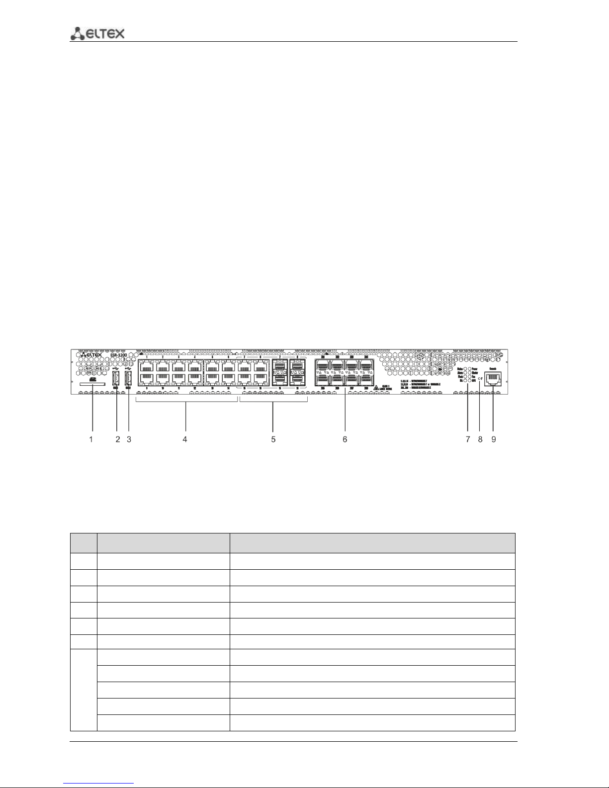
The front panel of ESR-1200 is represented in figure 2.1.
Figure 2.1 - Front panel of ESR-1200
The list of connectors, light indicators and controls that are located on the front panel of ESR-1200
are described in Table 2.1.
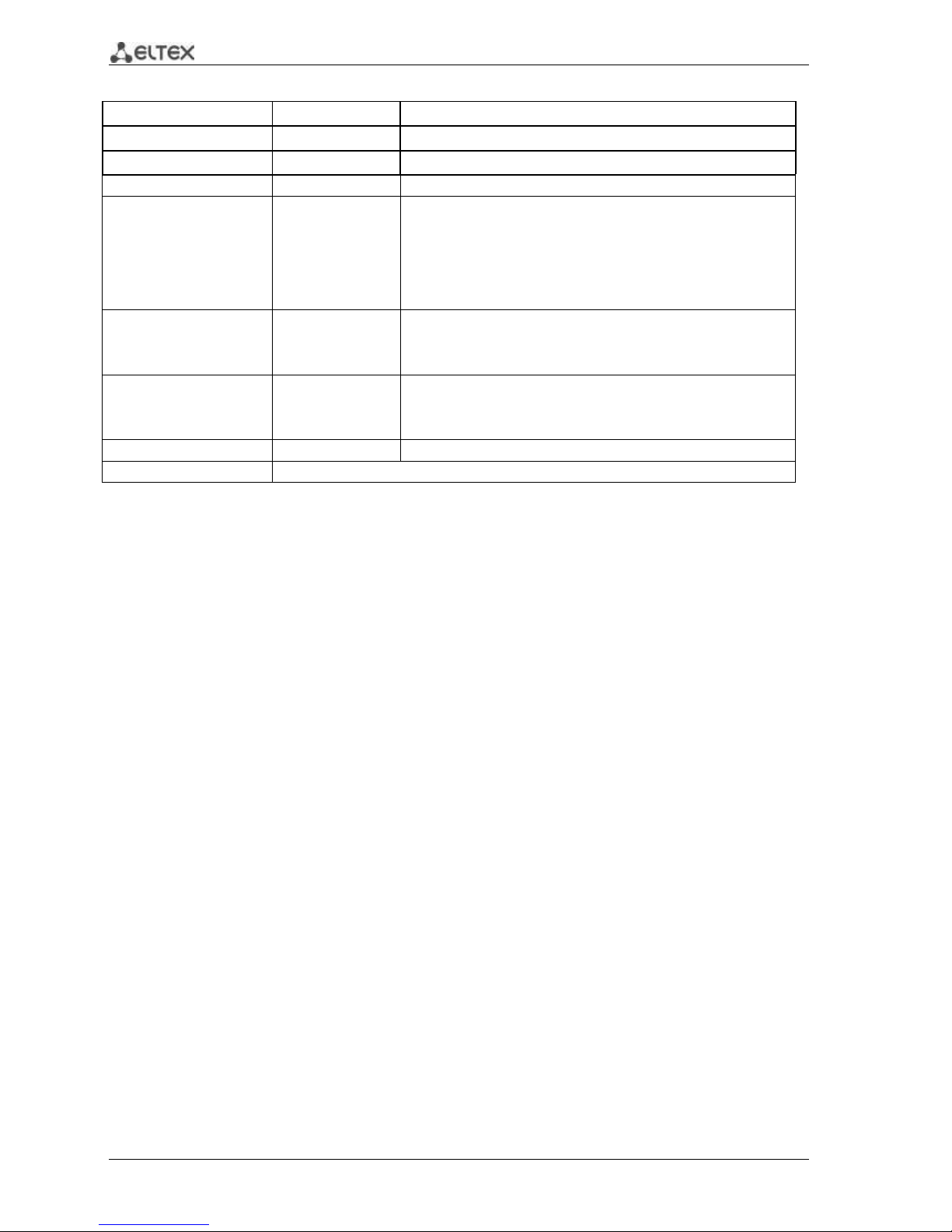
Table 2.1– Description of connectors, light indicators and controls located on the front panel of ESR-1200
№
Front panel element
Description
1
SD
SD-card connector.
2
USB1
USB-device port.
3
USB2
USB-device port.
4
[1 .. 12]
12 x Gigabit Ethernet 10/100/1000Base-T (RJ-45) ports.
5
Combo Ports
4 x Gigabit Ethernet 10/100/1000Base-X (SFP) ports.
6
XG1 - XG8
10G SFP+/ 1G SFP transceiver installation slots.
7
Status
Indicator of device's current state.
Alarm
indicator of alarm existence and emergency level.
HA
НА operation mode indicator.
Flash
Activity indicator of exchange with data storages (SD-card or USB Flash).
Power
Device power indicator.
ESR series routers 5
Master
Indicator of failover modes operation.
Fan
Fan alarm indicator.
RPS
Backup power source indicator.
8
F
Functional key that reboots the device and resets it to factory settings:
Pressing the key for less than 10 seconds reboots the
device;
Pressing the key for more than 10 seconds resets the
terminal to factory settings.
9
Console
Console port RS-232 for local management of the device.
ESR-1000 front panel
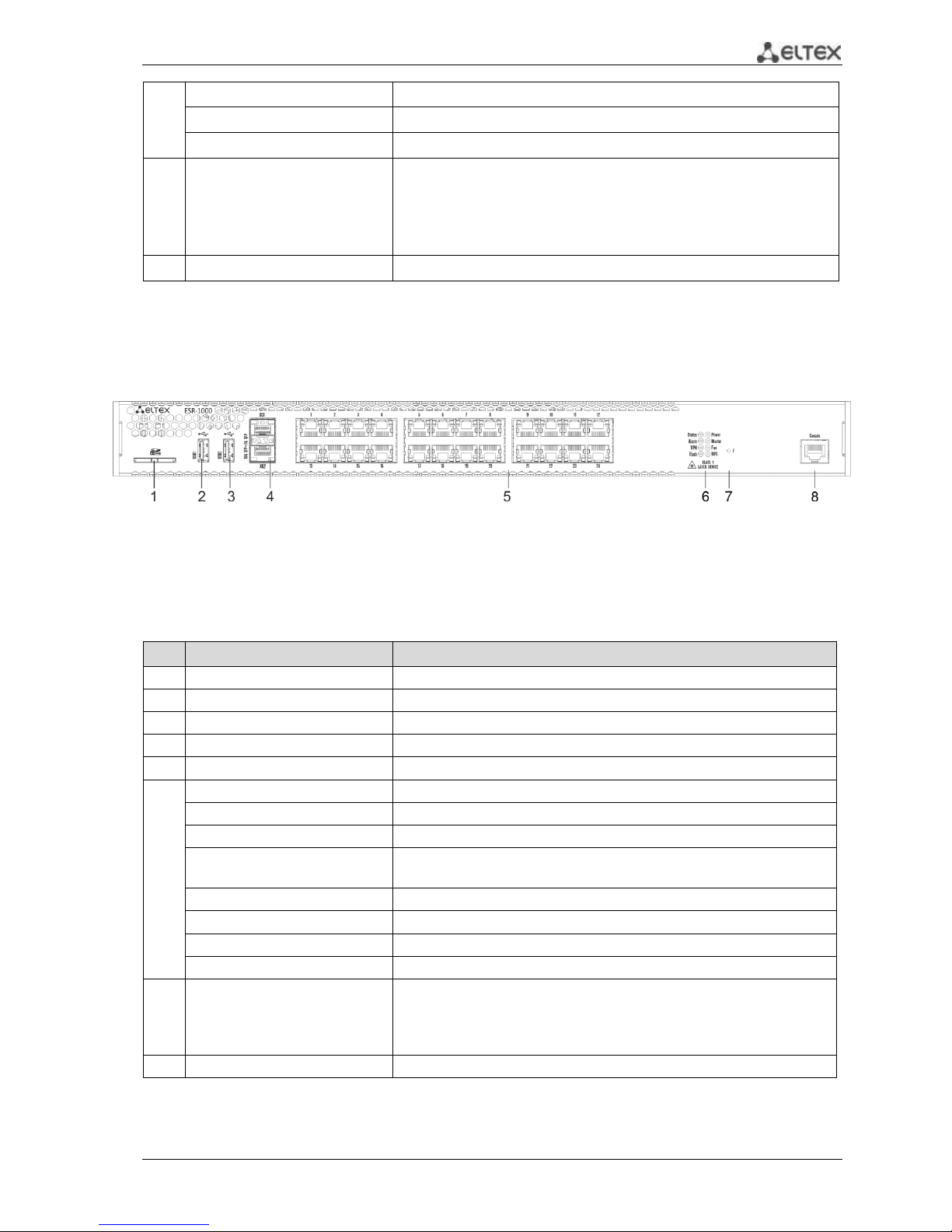
The front panel of ESR-1000 is represented in Figure 2.2
Figure 2.2– Front panel of ESR-1000
The list of connectors, light indicators and controls that are located on the front panel of ESR-1000
are described in Table 2.2
Table 2.2 – Description of connectors, light indicators and controls located on the front panel of ESR-1000
№
Front panel element
Description
1
SD
SD-card connector.
2
USB1
USB-device port.
3
USB2
USB-device port.
4
XG1, XG2
10G SFP+/ 1G SFP transceiver installation slots.
5
[1 .. 24]
24 Gigabit Ethernet 10/100/1000 Base-T (RJ-45) ports.
6
Status
Indicator of device's current state
Alarm
Existence and emergency level indicator of the device.
VPN
Existence indicator of active VPN-sessions
Flash
Activity indicator of exchange with data storages (SD-card or USB
Flash).
Power
Device power indicator.
Master
Operation indicator in failover-modes.
Fan
Emergency indicator of fans.
RPS
Reserve power supply indicator.
7
F
Functional key that reboots the device and resets it to factory settings:
– Pressing the key for less than 10 seconds reboots the device;
– Pressing the key for more than 10 seconds resets the terminal
to factory settings.
8
Console
RS-232 console port for local device control.
6 ESR series routers
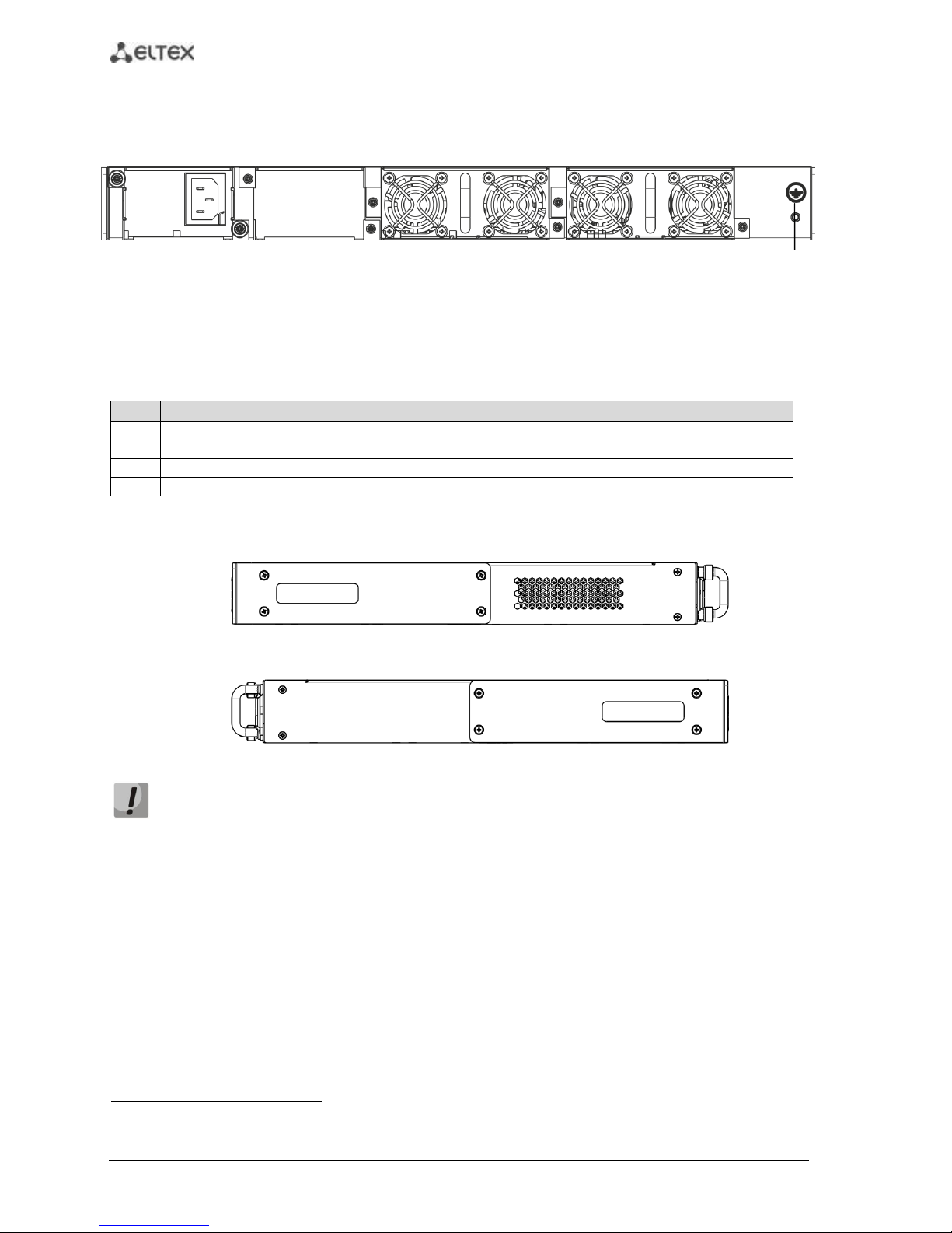
ESR-1000, ESR-12001 back panel
The back panel of ESR-1000/ESR-1200 is represented in figure 2.31.
Figure 2.3 – Back panel of ESR-1000, ESR-1200
The list of connectors located on the back panel of ESR1000/1200 is described in Table 2.3.
Table 2.3 – Description of connectors located on back panel of ESR-1000, ESR-1200
№
Description
1
Primary power supply source.
2
Place for reserve power supply installation.
3
Removable ventilation modules with hot swapping.
4
Device earth bonding point.
Side panel
Figure 2.4 - ESR-1000, ESR-1200 right-side panel
Figure 2.5 - ESR-1000, ESR-1200 left-side panel
Side panels of the device have air vents for heat removal. Do not block air vents. This may
cause components overheating which may result in terminal malfunction. You can find
recommendations on the device installation in 'Installation and connection' section in user
manual.
1
The picture shows router configuration with one AC power supply.
1 2 3
4
 Loading...