

Page 1

ESR Series Routers
ESR-100, ESR-200, ESR-1000, ESR-1200
Operation Manual, Firmware Ver. 1.2.0
Page 2

2 ESR Series Routers Operation Manual
Document version
Issue date
Revisions
Version 1.9
03.05.2017
Added chapters:
- 7.19.2 Policy-based IPSec VPN configuration
- 7.35 BRAS (Broadband Remote Access Server) configuration
Edited chapters:
- 2.3 Main specifications
- 2.4 Design
- 2.5 Delivery package
- 3.3 ESR-1000,ESR-1200 power module installation
- 5.1 ESR router factory settings
Version 1.8
14.12.2016
Added chapters:
- 7.2 Q-in-Q termination configuration
- 7.20 LT-tunnels configuration
- 7.31 VRRP tracking configuration
Version 1.7
Added chapters:
- 7.2 QinQ termination configuration
- 7.20 LT-tunnels configuration
- 7.31 VRRP tracking configuration
- 8 FAQ
Version 1.6
24/02/2016
Added chapters:
- 7.15.1 Configuring Route-map for BGP
- 7.21 Configuring remote access to corporate network via OpenVPN
protocol
- 7.31 SNMP configuration
Edited chapters:
- 7.15 PBR routing policy configuration
- 7.19 Configuring remote access to corporate network via PPTP
protocol
Version 1.5
06/08/2015
Added description for ESR-100, ESR-200
Added chapters:
- 2.4.2 ESR-100, ESR-200 design
Edited chapters:
- 2.4 Design
- 2.5 Delivery package
- 3 Installation and connection
- 7.1 VLAN configuration
- 7.6 Source NAT configuration
- 7.16 L2TPv3 tunnel configuration
- 7.24 Netflow configuration
- 7.25 sFlow configuration
- 7.26 LACP configuration
Version 1.4
09/06/2015
Added chapters:
- 6.1 ААА configuration
- 6.1 User privileges configuration
- 6.7 Access list (ACL) configuration
- 6.9 MLPPP configuration
- 6.14 Route-map configuration
- 6.21.2 Advanced QoS
- 6.24 VRF Lite configuration
Edited chapters:
- 2.4.4 Light indication
Version 1.3
05/03/2015
Added chapters:
- 6.15 Dual-Homing configuration
- 6.16 QoS configuration
- 6.17 Mirroring configuration
- 6.18 VRRP configuration
- 6.19 MultiWAN configuration
Edited chapters:
- 6.4 Firewall configuration
- 6.5 Static routes configuration
Page 3

ESR Series Routers Operation Manual 3
- 6.6 Bridge configuration
- 6.7 RIP configuration
- 6.8 OSPF configuration
- 6.9 BGP configuration
- 6.10 GRE tunnel configuration
- 6.11 L2TPv3 tunnel configuration
- 6.12 Route-based IPsec VPN configuration
- 6.13 Configuring remote access to corporate network via PPTP
protocol
- 6.14 Configuring remote access to corporate network via L2TP/IPsec
protocol
- 7.1 Updating firmware via system resources
- 7.2 Updating firmware via bootloader
Version 1.2
02/12/2014
Added chapters:
- 6.6 Bridge configuration
- 6.7 RIP configuration
- 6.8 OSPF configuration
- 6.9 BGP configuration
- 6.10 L3 tunnel (GRE) configuration
- 6.11 L2TPv3 tunnel (L2TPv3) configuration
Version 1.1
03/06/2014
Added: 6 Router configuration
Version 1.0
25/04/2014
First issue.
Firmware version
1.2.0
Page 4

4 ESR Series Routers Operation Manual
CONTENTS
1 INTRODUCTION .......................................................................................................................................... 6
1.1 Abstract ............................................................................................................................................... 6
1.2 Target Audience .................................................................................................................................. 6
1.3 Symbols ............................................................................................................................................... 6
2 PRODUCT DESCRIPTION ............................................................................................................................. 7
2.1 Purpose ............................................................................................................................................... 7
2.2 Functions............................................................................................................................................. 7
2.2.1 Interface functions .................................................................................................................... 7
2.2.2 Functions for MAC address processing ..................................................................................... 8
2.2.3 Second-layer functions of OSI model ........................................................................................ 8
2.2.4 Third-layer functions of OSI model ........................................................................................... 9
2.2.5 Traffic tunnelling functions ..................................................................................................... 10
2.2.6 Management and configuration functions ............................................................................. 10
2.2.7 Network security functions ..................................................................................................... 11
2.3 Main specifications ........................................................................................................................... 11
2.4 Design ............................................................................................................................................... 13
2.4.1 ESR-1000, ESR-1200 design ..................................................................................................... 13
2.4.2 ESR-100, ESR-200 design ......................................................................................................... 16
2.4.3 Light Indication ....................................................................................................................... 18
2.5 Delivery Package ............................................................................................................................... 20
3 INSTALLATION AND CONNECTION ........................................................................................................... 22
3.1 Support brackets mounting .............................................................................................................. 22
3.2 Device rack installation ..................................................................................................................... 23
3.3 ESR-1000, ESR-1200 power module installation .............................................................................. 24
3.4 Connection to Power Supply ............................................................................................................ 24
3.5 SFP transceiver installation and removal ......................................................................................... 25
4 MANAGEMENT INTERFACES .................................................................................................................... 26
4.1 Command line interface (CLI) ........................................................................................................... 26
5 INITIAL ROUTER CONFIGURATION ........................................................................................................... 27
5.1 ESR router factory settings ............................................................................................................... 27
5.2 Router connection and configuration ............................................................................................... 28
5.2.1 Connection to the router ........................................................................................................ 28
5.2.2 Basic router configuration ...................................................................................................... 29
6 FIRMWARE UPDATE ................................................................................................................................. 33
6.1 Updating firmware via system resources ......................................................................................... 33
6.2 Updating firmware via bootloader ................................................................................................... 34
6.3 Secondary bootloader update (U-Boot) ........................................................................................... 35
7 ROUTER CONFIGURATION EXAMPLES ...................................................................................................... 37
7.1 VLAN Configuration .......................................................................................................................... 37
7.2 QinQ termination configuration ....................................................................................................... 39
7.3 AAA configuration ............................................................................................................................. 39
7.4 Command privilege configuration .................................................................................................... 40
7.5 DHCP server configuration ............................................................................................................... 41
7.6 Destination NAT configuration ......................................................................................................... 43
7.7 Source NAT configuration ................................................................................................................. 45
7.8 Firewall configuration ....................................................................................................................... 48
7.9 Access list (ACL) configuration .......................................................................................................... 50
7.10 Static routes configuration ............................................................................................................... 51
7.11 MLPP configuration .......................................................................................................................... 53
7.12 Bridge configuration ......................................................................................................................... 54
7.13 RIP configuration .............................................................................................................................. 56
7.14 OSPF configuration ........................................................................................................................... 57
7.15 BGP configuration ............................................................................................................................. 60
Page 5

ESR Series Routers Operation Manual 5
7.16 PBR routing policy configuration ....................................................................................................... 63
7.16.1 Route-map for BGP configuration ........................................................................................ 63
7.16.2 Route-map based on access control lists (Policy-based routing) ......................................... 65
7.17 GRE tunnel configuration .................................................................................................................. 67
7.18 L2TPv3 tunnel configuration ............................................................................................................. 69
7.19 IPsec VPN configuration .................................................................................................................... 71
7.19.1 Route-based IPsec VPN configuration: ................................................................................. 71
7.19.2 Policy-based IPSec VPN configuration .................................................................................. 74
7.20 LT-tunnels configuration ................................................................................................................... 77
7.21 Configuring remote access to corporate network via PPTP protocol ............................................... 78
7.22 Configuring remote access to corporate network via L2TP/IPsec protocol ...................................... 80
7.23 Configuring remote access to corporate network via OpenVPN protocol ........................................ 82
7.24 Dual-Homing Configuration ............................................................................................................... 83
7.25 QoS configuration .............................................................................................................................. 84
7.25.1 Basic QoS .............................................................................................................................. 85
7.25.2 Extended QoS ....................................................................................................................... 86
7.26 Mirroring configuration ..................................................................................................................... 88
7.27 Netflow configuration ....................................................................................................................... 89
7.28 sFlow configuration ........................................................................................................................... 90
7.29 LACP configuration ............................................................................................................................ 91
7.30 VRRP configuration ............................................................................................................................ 92
7.31 VRRP tracking configuration .............................................................................................................. 94
7.32 VRF Lite configuration ....................................................................................................................... 96
7.33 MultiWAN configuration ................................................................................................................... 98
7.34 SNMP configuration......................................................................................................................... 100
7.35 BRAS (Broadband Remote Access Server) configuration ................................................................ 101
8 FREQUENTLY ASKED QUESTIONS ........................................................................................................... 107
Page 6
6 ESR Series Routers Operation Manual
1 INTRODUCTION
1.1 Abstract
Today, large-scale communication network development projects are becoming increasingly
common. One of the main tasks in implementation of large multiservice networks is the creation of
reliable high-performance transport network that will serve as a backbone in multilayer architecture of
next-generation networks.
ESR series routers could be used in large enterprise networks, SMB networks and operator's
networks. Devices provide high performance and bandwidth, and feature protection of transmitted data.
This operation manual describes intended use, specifications, features, design, installation, first
time setup, and firmware update guidelines for the ESR series router. (next, the device)
1.2 Target Audience
This user manual is intended for technical personnel that performs device installation, configuration
and monitoring via command line interface (CLI) as well as the system maintenance and firmware update
procedures. Qualified technical personnel should be familiar with the operation basics of TCP/IP protocol
stacks and Ethernet networks design concepts.
1.3 Symbols
Symbol
Description
Calibri italic
Variables and parameters that should be replaced with the appropriate word
or string are written in Calibri Italic.
Semibold font
Notes and warnings are written in semibold font.
<Semibold italic>
Keyboard keys are enclosed in angle brackets.
Courier New
Examples of command entry are written in Courier New semibold.
Courier New
Results of command execution are written in Courier New font in a frame
with the shadow border.
[ ]
In the command line, optional parameters are shown in square brackets;
when entered, they provide additional options.
{ }
In the command line, mandatory parameters are shown in curly braces.
Choose one of the following:
|
In the description of the command, this sign means 'or'.
Notes and warnings
Notes contain important information, tips or recommendations on device operation and
setup.
Warnings are used to inform the user about harmful situations for the device and the
user alike, which could cause malfunction or data loss.
Page 7

ESR Series Routers Operation Manual 7
2 PRODUCT DESCRIPTION
2.1 Purpose
ESR series devices are the high performance multi-purpose network routers. Device combines
traditional network features with a complex multi-tier approach to routing security, and ensures robust
corporate environment protection.
Device has a built-in firewall that enables protection of your network environment and supports
latest data security, encryption, authentication and anti-intrusion features.
Device contains software and hardware means of data processing. Top performance is achieved
through optimal distribution of data processing tasks between different subsets of the device.
2.2 Functions
2.2.1 Interface functions
Table 2.1 lists interface functions of the device.
Table 2.1 – Device interface functions
Cable connection
polarity detection
(Auto MDI/MDIX)
Automatic cable type detection—crossed or straight.
– MDI (Media-Dependent Interface—straight)—cable standard for
connection of terminal devices
– MDIX (Media-Dependent Interface with Crossover—crossed)—cable
standard for connection of hubs and switches
Backpressure routing
support
(Back pressure)
The backpressure routing method is utilized in half-duplex connections for
management of data streams, coming from the opposite devices, by means of
collisions. This method allows to avoid buffer overruns and the loss of data.
Flow control
(IEEE 802.3X)
Flow control allows to interconnect the low-speed and the high-speed devices. To
avoid buffer overrun, the low-speed device gains the ability to send PAUSE
packets, that will force the high-speed device to pause the packet transmission.
Link aggregation
(LAG)
Link aggregation allows to increase the communication link bandwidth and
robustness.
Router supports static and dynamic link aggregation. For dynamic aggregation, link
group management is performed via LACP protocol.
Page 8

8 ESR Series Routers Operation Manual
2.2.2 Functions for MAC address processing
Table 2.2 lists MAC address processing functions of the device
Table 2.2 —MAC address processing functions
MAC address
table
MAC address table sets the correspondence between MAC addresses and device
interfaces and is used for data packet routing. Routers support table capacity up to
16K of MAC addresses and reserve specific MAC addresses for the system use.
Learning mode
MAC address table may contain either static addresses or addresses learnt during
data packet transition through the device.
Learning involves registration of packet source MAC addresses with their binding
to ports and VLANs. Afterwards, this data is used for incoming packet routing.
Registered MAC address lifetime is limited. Administrator may adjust this setting.
If destination MAC address specified in the packet that was received by the device
is not listed in the table, this packet will be sent further as a broadcast packet
within L2 segment of the network.
2.2.3 Second-layer functions of OSI model
Table 2.3 lists second-layer functions and special aspects (OSI Layer 2).
Table 2.3 —Second-layer functions description (OSI Layer 2)
VLAN support
VLAN (Virtual Local Area Network) is a solution used for splitting a network into
separate segments on L2 level. VLAN utilization allows to increase the operation
stability for large networks by splitting them into smaller networks, isolate
diversified data traffic by type and solve many other tasks.
Routers support various VLAN management methods:
– VLAN based on data packet tagging according to IEEE802.1Q
– VLAN based on device ports (port-based)
– VLAN based on utilization of data classification policies (policy-based)
Spanning Tree Protocol
(STP) 1
The main task of Spanning Tree Protocol is to exclude redundant network links and
convert network topology into the tree-like structure. Common areas of protocol
application involve the prevention of network traffic loops and establishing of
redundant communication links.
1
In the current firmware version, this functionality is supported only by ESR-1000 router.
Page 9

ESR Series Routers Operation Manual 9
2.2.4 Third-layer functions of OSI model
Table 2.4 lists third-layer functions (OSI Layer 3).
Table 2.4 —Third-layer functions description (OSI Layer 3)
Static IP routes
Administrator of the router can add or remove static records into/from the routing
table.
Dynamic routing
With dynamic routing protocols, the device will be able to exchange the routing
information with neighbouring routers and automatically create a routing table.
Router supports the following protocols: RIP, OSPFv2, OSPFv3, BGP.
ARP table
ARP (Address Resolution Protocol) is a protocol used for resolution of the network
and data-link layer addresses. ARP table contains information on the established
correspondence.
Correspondence is established on the basis of the network device response
analysis; device addresses are requested with broadcast packets.
DHCP client
DHCP (Dynamic Host Configuration Protocol) protocol enables automation of
the network device management process.
DHCP client allows the router to obtain the network address and additional
settings from the external DHCP server. As a rule, this method is used for obtaining
network settings of a public network operator (WAN).
DHCP server
DHCP server enables automation and centralization of the network device
configuration process.
DHCP server allocated on a router allows for a complete solution for the local area
network support.
DHCP server integrated into the router assigns IP addresses to network devices
and transfers additional network settings, e.g. server addresses, network gateway
addresses and other necessary settings.
Network Address
Translation
(NAT)
Network address translation is a mechanism that translates IP addresses and port
numbers for transit packets.
NAT function allows to minimize the quantity of IP address used through
translation of multiple internal network IP addresses into a single external public
IP address. NAT conceals local area network internal structure and allows to
enhance its security.
Routers support the following NAT options:
– Source NAT (SNAT)—the network address and the source port number
will be replaced, when packet is transferred forth, and the destination
address will be replaced in the response packet.
– Destination NAT (DNAT)—external access is translated by the firewall to
the user computer in LAN that has an internal address and thus directly
inaccessible from outside the network.
Page 10

10 ESR Series Routers Operation Manual
2.2.5 Traffic tunnelling functions
Table 2.5 —Traffic tunnelling functions
Tunnelling
protocols
Tunnelling is a method of packet conversion during their network transfer that
involves the replacement, modification and addition of a new packet network
header. This method may be used for negotiation of transport protocols when the
data is transferred through the transit network as well as for creation of secured
connections where tunnelled data is being encrypted.
Routers support the following types of tunnels:
– GRE—IP packet is encapsulated into another IP packet with GRE (General
Routing Encapsulation) header
– IPv4-IPv4—tunnel that encapsulates source IP packets into IP packets
with alternative network parameters
– L2TPv3—tunnel for L2 traffic transmission using IP packets
– IPsec—tunnel with the encryption of transmitted data
– L2TP, PPTP—tunnels used for establishing a remote 'client-sever' access
2.2.6 Management and configuration functions
Table 2.6 —Basic management and configuration functions
Configuration file
download and upload
Device parameters are saved into the configuration file that contains configuration
data for the specific device ports as well as for the whole system. The following
protocols may be used for file transfers: TFTP, FTP, and SCP.
Command line interface
(CLI)
CLI management is performed locally via serial port RS-232, or remotely via Telnet,
SSH. Console command line interface (CLI) is the industrial standard. CLI
interpreter contains the list of commands and keywords that will help the user and
reduce the amount of input data.
Syslog
Syslog protocol is designed for transmission of system event messages and event
logging.
Network utilities:
ping, traceroute
ping and traceroute utilities allow you to check the availability of network devices
and identify data transfer routes in IP networks.
Controlled access
management—
privilege levels
Routers support system access level management for users. Access levels enable
responsibility areas management for device administrators. Access levels are
numbered from 1 to 15; Level 15 stands for full access to device management
features.
Authentication
Authentication is a user identity check procedure. Routers support the following
authentication methods:
– local—local user database stored on the device is used for authentication
– group—user database is located on the authentication server RADIUS
and TACACS protocols are user for server interactions.
SSH server
Telnet server
SSH and Telnet server features allow you to establish connection to the device
and perform device management.
Automatic
configuration restore
Device features automatic configuration restore system designed to prevent
remote access loss after re-configuration. If the configuration change is not
confirmed in the defined time, configuration will be rolled back to the last known
state.
Page 11
ESR Series Routers Operation Manual 11
2.2.7 Network security functions
The table lists network security functions of the device.
Table 2.7 —Network security functions
Security zones
All router interfaces are distributed by security areas.
For each zone pair, you can set the rules that define the possibility of data
transmission between zones, data traffic filtering rules.
Data filtering
For each zone pair, you can define the rule set that manages the filtering process
for data transmitted through the router.
Device command interface provides appropriate means for detailed configuration
of the traffic classification rules and to apply the resulting solution for traffic
transmission.
2.3 Main specifications
Table 2.8 lists main specifications of the router.
Table 2.8 —Main specifications
General parameters
Packet processor
ESR-1200
ESR-1000
Broadcom XLP316L
ESR-200
Broadcom XLP204
ESR-100
Broadcom XLP104
Interfaces
ESR-1200
12 x Ethernet 10/100/1000Base-T
4 x Ethernet 10/100/1000Base-T/1000Base-X Combo
8 x 10GBase-R/1000Base-X (SFP+/SFP)
ESR-1000
24 x Ethernet 10/100/1000Base-T
2 x 10G Base Base-R/1000Base-X (SFP+/SFP)
ESR-200
x Ethernet 10/100/1000Base-T / 1000 Base-X Combo
4 x Ethernet 10/100/1000Base-T
ESR-100
x Ethernet 10/100/1000Base-T / 1000 Base-X Combo
Types of optical
transceivers
ESR-1200
ESR-1000
1000BASE-X SFP, 10GBASE-R SFP+
ESR-100
ESR-200
1000BASE-X SFP
Duplex or half-duplex interface modes
- duplex and half-duplex modes for electric ports
- duplex mode for optical ports
ESR-1000 router maximum bandwidth
(hardware switching)
88Gbps
Integrated switch buffer memory
(for ESR-1000)
12Mb
Data transfer rate
ESR-1200
ESR-1000
- electric interfaces 10/100/1000Mbps
- optical interfaces 1/10Gbps
ESR-100
ESR-200
- electric interfaces 10/100/1000Mbps
- optical interfaces 1Gbps
MAC address table
(for ESR-1000)
16K records
VLAN support
up to 4K active VLANs according to 802.1Q
Quantity of L3 interfaces
up to 2K
Quantity of BGP routes
ESR-1200
ESR-1000
2,6M
ESR-100
ESR-200
1,2M
Page 12
12 ESR Series Routers Operation Manual
Quantity of OSPF routes
ESR-1200
ESR-1000
500K
ESR-100
ESR-200
300K
Quantity of RIP routes
10K
Quantity of static routes
11K
FIB size
ESR-1200
ESR-1000
1,7M
ESR-100
ESR-200
550K
Compliance
IEEE 802.3 10BASE-T Ethernet
IEEE 802.3u 100BASE-T Fast Ethernet
IEEE 802.3ab 1000BASE-T Gigabit Ethernet
IEEE 802.3z Fiber Gigabit Ethernet
ANSI/IEEE 802.3 Speed autodetection
IEEE 802.3x Data flow control
IEEE 802.3ad LACP link aggregation
IEEE 802.1q VLAN virtual local networks
IEEE 802.1v
IEEE 802.3ac
IEEE 802.3ae
IEEE 802.1D
IEEE 802.1w
IEEE 802.1s
Control
Local control
CLI
Remote control
TELNET, SSH
Physical specifications and ambient conditions
Power supply
ESR-1200
ESR-1000
AC: 220V+-20%, 50Hz
DC: -36 .. - 72V
Power options:
- Single AC or DC power supply
- Two AC or DC power supplies with hot swapping
ESR-100
ESR-200
AC: 220V+-20%, 50Hz
Maximum power
consumption:
ESR-1200
85W
ESR-1000
75W
ESR-100
20W
ESR-200
25W
Weight
ESR-1200
5.5kg max.
ESR-1000
3.6kg max.
ESR-100
ESR-200
2.5kg max.
Dimensions
ESR-1200
ESR-1000
430x352x44mm
ESR-100
ESR-200
310х240х44mm
Operating temperature range
-10 to +45°C
Storage temperature range
-40 to +70оС
Operation relative humidity (noncondensing)
up to 80%
Storage relative humidity (noncondensing)
from 10% to 95%
Average lifetime
20 years
Page 13
ESR Series Routers Operation Manual 13
2.4 Design
This section describes the design of the device. Depicted front, rear, and side panels of the device,
connectors, LED indicators and controls.
The device has a metal housing available for 19” form-factor rack mount; housing size is 1U.
2.4.1 ESR-1000, ESR-1200 design
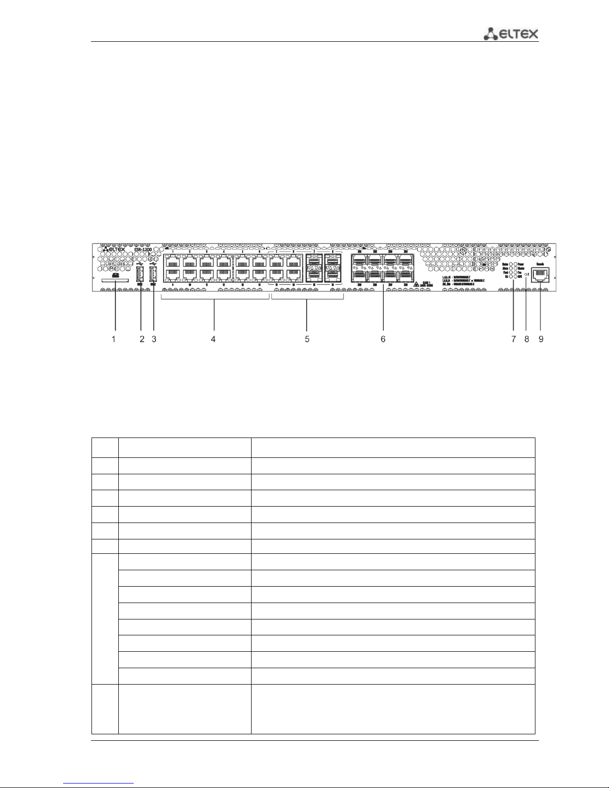
2.4.1.1 ESR-1200 front panel
The front panel of ESR-1200 is depicted in Fig. 2.1.
Fig. 2.1 - Front panel of ESR-1200
The list of connectors, light indicators and controls located on the front panel of ESR-1200 lists in
Table 2.9
Table 2.9 - Description of connectors, indicators and controls located on the front panel of ESR-1200
№
Front panel element
Description
1
SD
SD-card connector.
2
USB1
USB-device port.
3
USB2
USB-device port.
4
[1 .. 12]
12 x Gigabit Ethernet 10/100/1000Base-T (RJ-45) ports.
5
Combo Ports
4 x Gigabit Ethernet 10/100/1000Base-X (SFP) ports.
6
XG1 - XG8
10G SFP+/ 1G SFP transceiver installation slots.
7
Status
Indicator of device's current state.
Alarm
indicator of alarm existence and emergency level.
HA
НА operation mode indicator.
Flash
Activity indicator of exchange with data storages (SD-card or USB Flash).
Power
Device power indicator.
Master
Indicator of failover modes operation.
Fan
Fan alarm indicator.
RPS
Backup power source indicator.
8
F
Functional key that reboots the device and resets it to factory settings:
Pressing the key for less than 10 seconds reboots the
device;
Pressing the key for more than 10 seconds resets the
Page 14
14 ESR Series Routers Operation Manual
terminal to factory settings.
9
Console
Console port RS-232 for local management of the device.
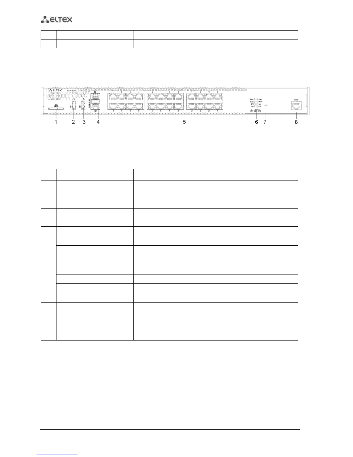
2.4.1.2 ESR-1000 front panel
The front panel layout of the device is depicted in Fig. 2.2.
Fig. 2.2 —ESR-1000 front panel
Table 2.10 lists sizes, LEDs, and controls located on the front panel of the device.
Table 2.10 —Description of connectors, LEDs, and controls located on the front panel
No.
Front panel element
Description
1
SD
SD memory card installation slot.
2
USB1
USB-enabled devices connection port.
3
USB2
USB-enabled devices connection port.
4
XG1, XG2
10G SFP+/ 1G SFP transceivers installation slots.
5
[1 .. 24]
24 x Gigabit Ethernet 10/100/1000 Base-T (RJ-45) ports.
6
Status
Current device status indicator.
Alarm
Device alarm presence and level indicator.
VPN
Active VPN sessions indicator.
Flash
Data storage activity indicator—SD card or USB Flash
Power
Device power indicator.
Master
Device failover mode operation indicator.
Fan
Fan alarm indicator.
RPS
Backup power supply indicator.
7
F
Functional key that reboots the device and resets it to factory settings:
– Pressing the key for less than 10 seconds reboots the device.
– Pressing the key for more than 10 seconds resets the device to
factory settings.
8
Console
RS-232 console port for local control of the device.
Page 15
ESR Series Routers Operation Manual 15
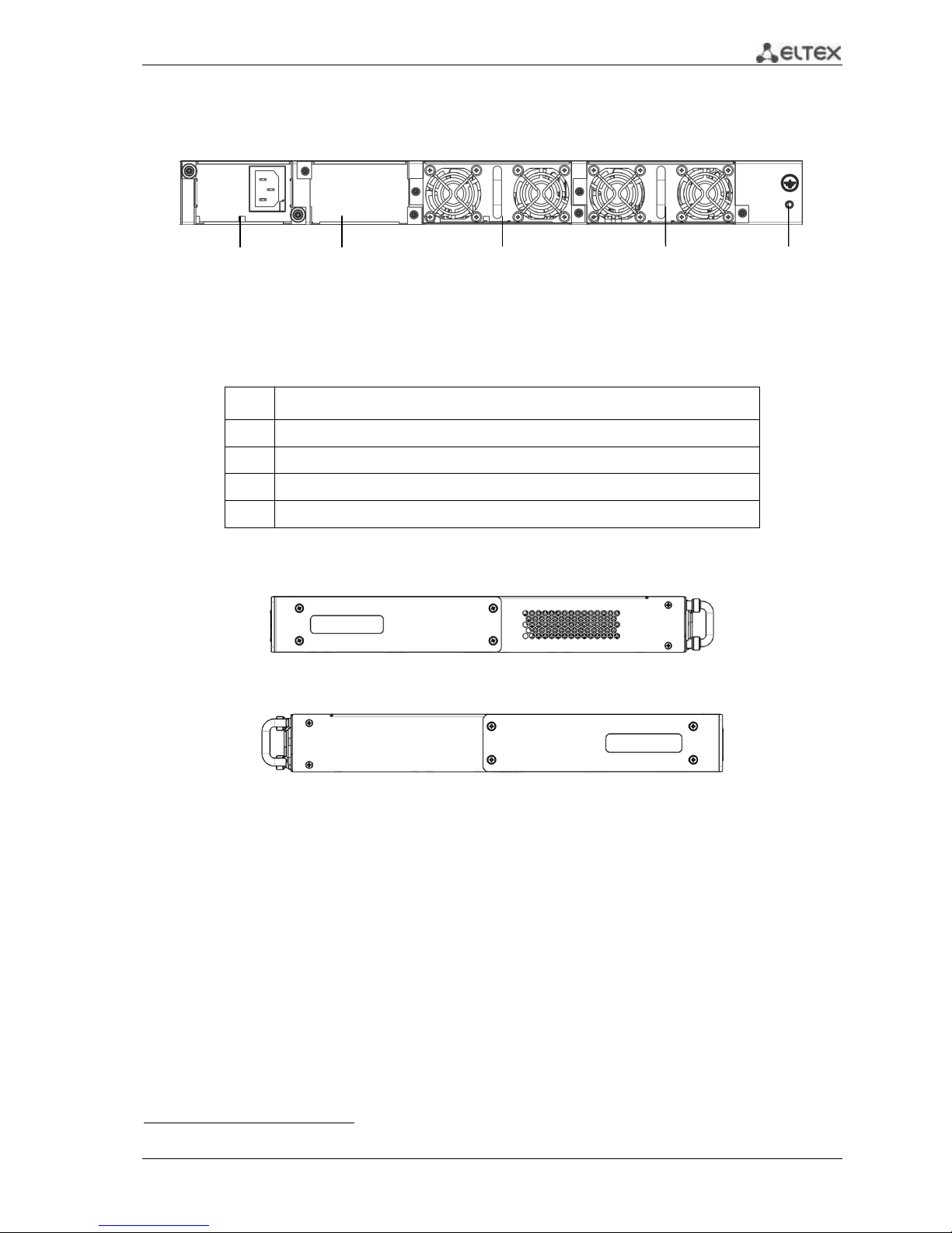
2.4.1.3 ESR-1000, ESR-1200 rear panel
The rear panel layout of ESR-1000, ESR-1200 is depicted in Fig. 2.31.
Fig. 2.3 —ESR-1000, ESR-1200 rear panel
Table 2.11 lists rear panel connectors of the router.
Table 2.11 —Description of rear panel connectors of the router
No.
Description
1
Main power supply.
2
Backup power supply installation position.
3
Removable ventilation modules with hot-swapping.
4
Earth bonding point of the device.
2.4.1.4 Side panels of the device
Fig. 2.4 —The right-side panel of ESR-1000, ESR-1200 routers
Fig. 2.5—The left-side panel of ESR-1000, ESR-1200 routers
Side panels of the device have air vents for heat removal. Do not block air vents. This may cause
components overheating which may result in terminal malfunction. For recommendations on device
installation, see section 'Installation and connection'.
1
The figure shows the router delivery package with a single AC power supply.
1 2 3 3 4
Page 16
16 ESR Series Routers Operation Manual
2.4.2 ESR-100, ESR-200 design
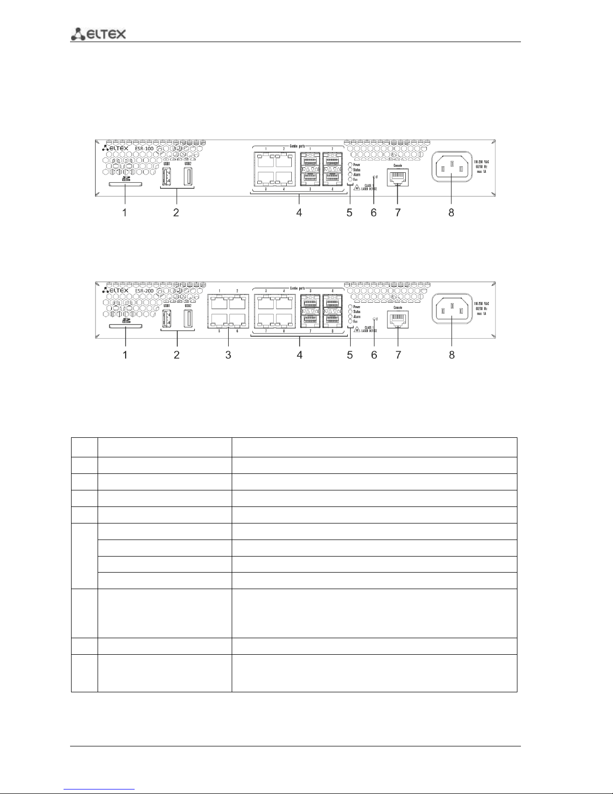
2.4.2.1 ESR-100, ESR-200 front panel
The front panel layout of ESR-100 is depicted in Fig. 2.6.
Fig. 2.6 —ESR-100 front panel
The front panel layout of ESR-200 is depicted in Fig. 2.7.
Fig. 2.7 —ESR-200 front panel
Table 2.12 lists sizes, LEDs, and controls located on the front panel of ESR-100 and ESR-200 routers.
Table 2.12 —Description of connectors, LEDs, and controls located on the front panel
No.
Front panel element
Description
1
SD
SD memory card installation slot.
2
USB1, USB2
2 x USB-enabled devices connection port.
3
[1 .. 4]
4 x Gigabit Ethernet 10/100/1000 Base-T (RJ-45) ports.
4
Combo Ports
4 x Gigabit Ethernet 10/100/1000 Base-X (SFP) ports
5
Power
Device power indicator.
Status
Current device status indicator.
Alarm
Device alarm presence and level indicator.
Fan
Fan alarm indicator.
6
F
Functional key that reboots the device and resets it to factory settings:
– Pressing the key for less than 10 seconds reboots the device.
– Pressing the key for more than 10 seconds resets the device to
factory settings.
7
Console
RS-232 console port for local control of the device.
8
110-250VAC
60/50Hz
max 1A
Power supply
Page 17
ESR Series Routers Operation Manual 17
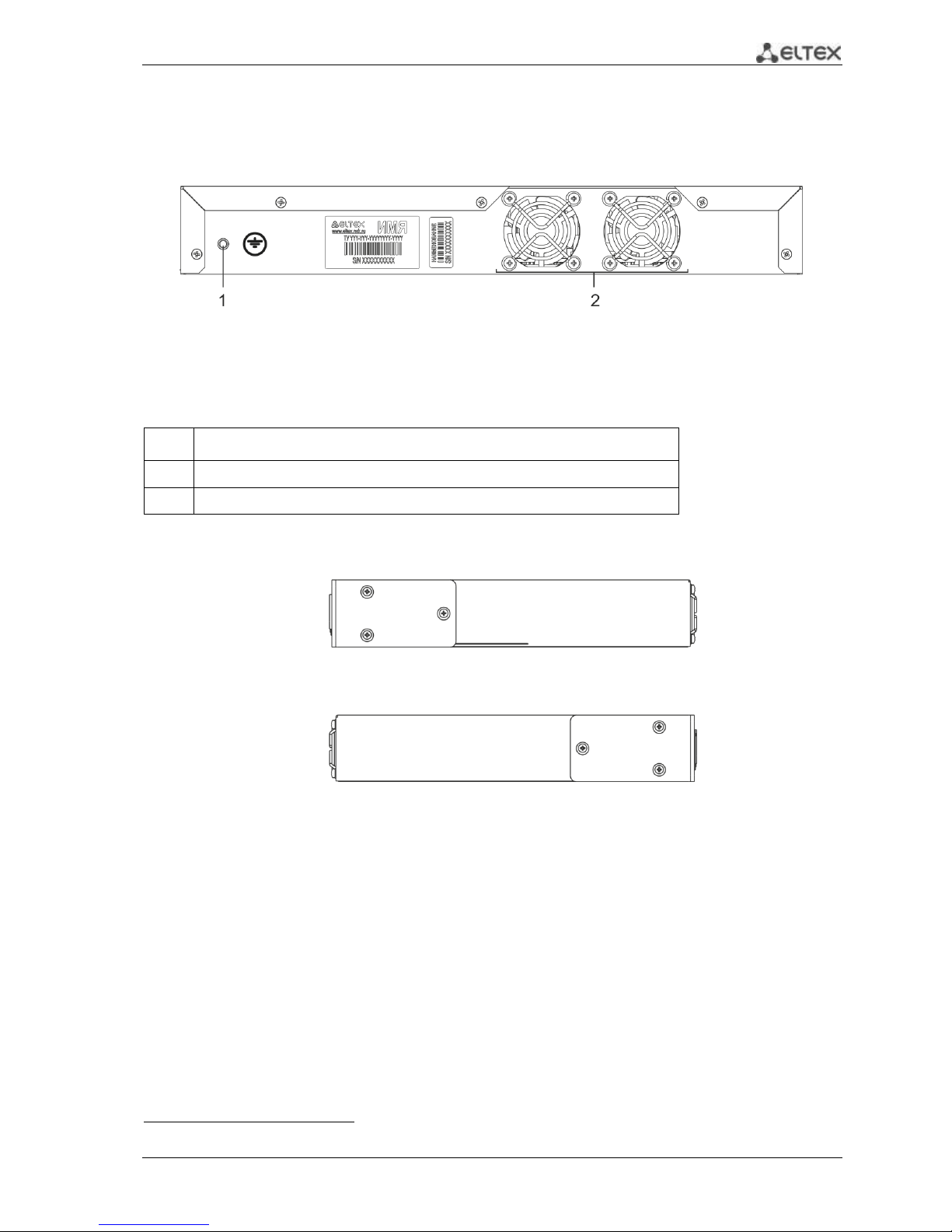
2.4.2.2 ESR-100, ESR-200 rear panel
The rear panel layout of ESR-100 and ESR-200 routers is depicted in Fig. 2.81.
Fig. 2.8 —ESR-1000, rear panel
Table 2.13 lists rear panel connectors of the router.
Table 2.13 —Description of rear panel connectors of the router
No.
Description
1
Earth bonding point of the device.
2
Ventilation module.
2.4.2.3 ESR-100, ESR-200 side panels
Fig. 2.9 —The right-side panel of ESR-100 and ESR-200 routers
Fig. 2.10—The left-side panel of ESR-100 and ESR200 routers
1
The figure shows the router delivery package with a single AC power supply.
Page 18
18 ESR Series Routers Operation Manual
2.4.3 Light Indication
2.4.3.1 ESR-1000, ESR-1200 light indication
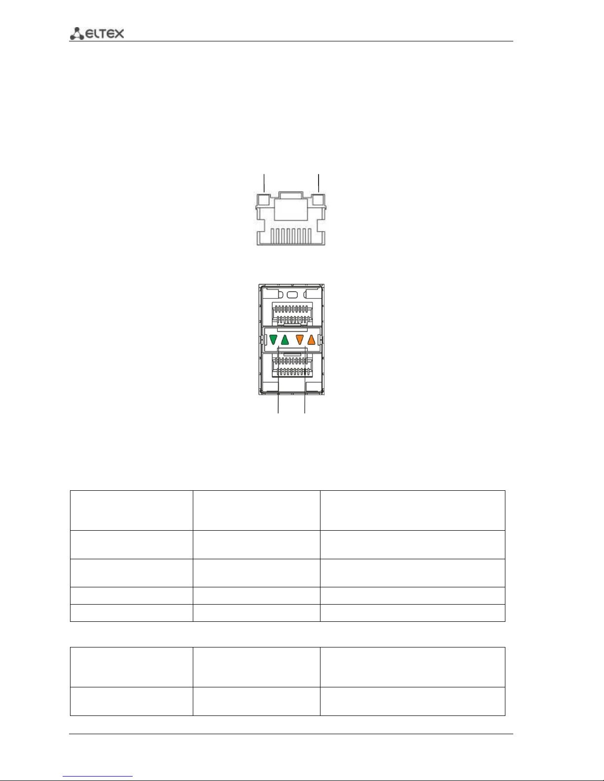
Gigabit Ethernet copper interface status is represented by two LEDs—green LINK/ACT LED and
amber SPEED LED. Location of the copper interface LEDs is depicted in Fig. 2.11. SFP interface status is is
represented by two LEDs—RX/ACT and TX/ACT—depicted in Fig. 2.12. For light indication meaning, see
Tables 2.14 and 2.15.
Fig. 2.11 —Location of RJ-45 port indicators
Fig. 2.12 —Location of optical interface indicators
Table 2.14 —Light indication of copper interface status
SPEED indicator is lit
LINK/ACT indicator is lit
Ethernet interface state
Off
Off
Port is disabled or connection is not
established
Off
Solid on
10Mbps or 100Mbps connection is
established
Solid on
Solid on
1000Mbps connection is established
X
Flashes
Data transfer is in progress
Table 2.15 —Light indication of SFP/SFP+ interface status
RX/ACT indicator is lit
TX/ACT indicator is lit
Ethernet interface state
Off
Off
Port is disabled or connection is not
established
LINK/ACT
SPEED
RX/ACT
TX/ACT
Page 19
ESR Series Routers Operation Manual 19
Solid on
Solid on
Connection established
Flashes
X
Data reception in progress
X
Flashes
Data transfer in progress
The following table lists description of system indicator statuses and meanings.
Table 2.16 —Status of system indicators
Indicator
name
Indicator function
LED State
Device State
Status
Current device status indicator.
Green
Device is in normal operation state.
Orange
Device is booting up the software.
Alarm
Device alarm presence and level
indicator.
-
-
VPN
Active VPN sessions indicator.
-
-
Flash
Data storage activity indicator: SD
card or USB Flash.
Orange
Read/write operation execution with
'copy' command
Power
Device power indicator.
Green
Device power is OK. Main power
supply, if installed, is operational.
Orange
Main power supply failure or fault, or
the primary main is missing.
Off
Device internal power supply failure.
Master
Device failover mode operation
indicator.
-
-
Fan
Cooling fan status.
Off
All fans are operational.
Red
One or more fans has failed. Possible
cause of failure: at least one of the fans
has stopped or is working at lower
rpm.
RPS
Backup power supply operation
mode.
Green
Backup power supply is installed and
operational.
Off
Backup power supply is not installed.
Red
Backup power supply is missing or
failed.
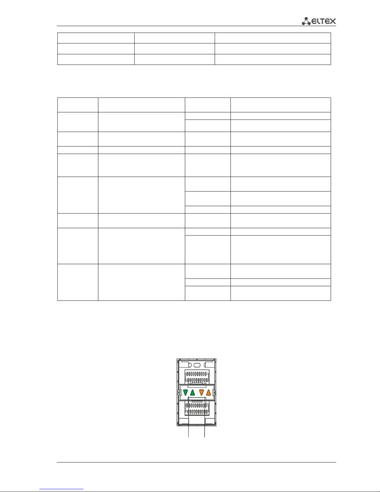
2.4.3.2 ESR-100/ESR-200 light indication
Gigabit Ethernet copper interface and SFP interface statuses are represented by two LEDs—green
LINK/ACT LED and amber SPEED LED. Location of the copper interface LEDs is depicted in Fig. 2.11. SFP
interface status is depicted in Fig. 2.13. For light indication meaning, see Table 2.17.
Fig. 2.13 —Location of optical interface indicators
LINK/ACT
SPEED
Page 20
20 ESR Series Routers Operation Manual
Table 2.17 —Light indication of copper and SFP interface status
SPEED indicator is lit
LINK/ACT indicator is lit
Ethernet interface state
Off
Off
Port is disabled or connection is not
established
Off
Solid on
10Mbps or 100Mbps connection is
established
Solid on
Solid on
1000Mbps connection is established
X
Flashes
Data transfer in progress
The following table lists description of system indicator statuses and meanings.
Table 2.18 —Status of system indicators
Indicator
name
Indicator function
LED State
Device State
Status
Current device status indicator.
Green
Device is in normal operation state.
Orange
Device is booting up the software.
Alarm
Device alarm presence and level
indicator. 1
-
-
Power
Device power indicator.
Green
Device power is OK. Main power
supply, if installed, is operational.
Orange
Main power supply failure or fault, or
the primary main is missing.
Off
Device internal power supply failure.
Fan
Cooling fan status.
Off
All fans are operational.
Red
One or more fans has failed. Possible
cause of failure: at least one of the fans
has stopped or is working at lower
rpm.
2.5 Delivery Package
ESR-100 standard delivery package includes:
ESR-100 router
Power cable
Console port connection cable (RJ-45 – DB9F)
19” rack mounting kit
Documentation
ESR-200 standard delivery package includes:
ESR-200 router
Power cable
Console port connection cable (RJ-45 – DB9F)
19” rack mounting kit
Documentation
1
Not supported in the current firmware version.
Page 21
ESR Series Routers Operation Manual 21
ESR-1000 standard delivery package includes:
ESR-1000 router
Power cable
Console port connection cable (RJ-45 – DB9F)
19” rack mounting kit
Documentation
ESR-1200 standard delivery package includes:
– ESR-1200 router;
– power cable;
– Console port connection cable (RJ-45 – DB9F);
– 19” rack mounting kit;
– Documentation.
Power module (PM-160-220/12 or PM-75-48/12) may be included in the ESR-1000 delivery
package on the customer's request.
SFP/SFP+ transceivers may be included in the delivery package on the customer's request.
Page 22
22 ESR Series Routers Operation Manual
3 INSTALLATION AND CONNECTION
This section describes installation of the device into a rack and connection to a power supply.
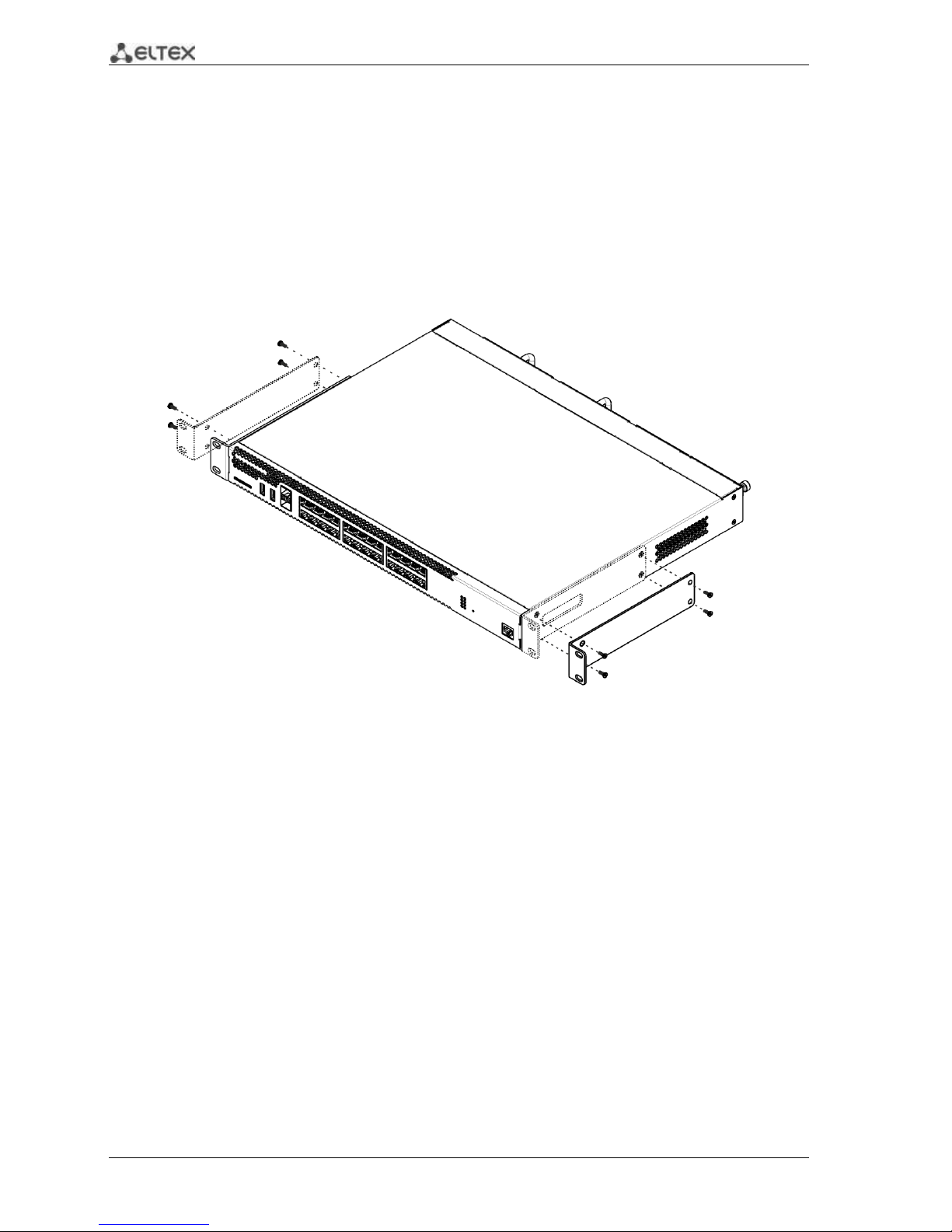
3.1 Support brackets mounting
The delivery package includes support brackets for rack installation and mounting screws to fix the
device case on the brackets. To install the support brackets:
Fig. 3.1 —Support brackets mounting
1. Align four mounting holes in the support bracket with the corresponding holes in the side
panel of the device.
2. Use a screwdriver to screw the support bracket to the case.
3. Repeat steps 1 and 2 for the second support bracket.
Page 23
ESR Series Routers Operation Manual 23
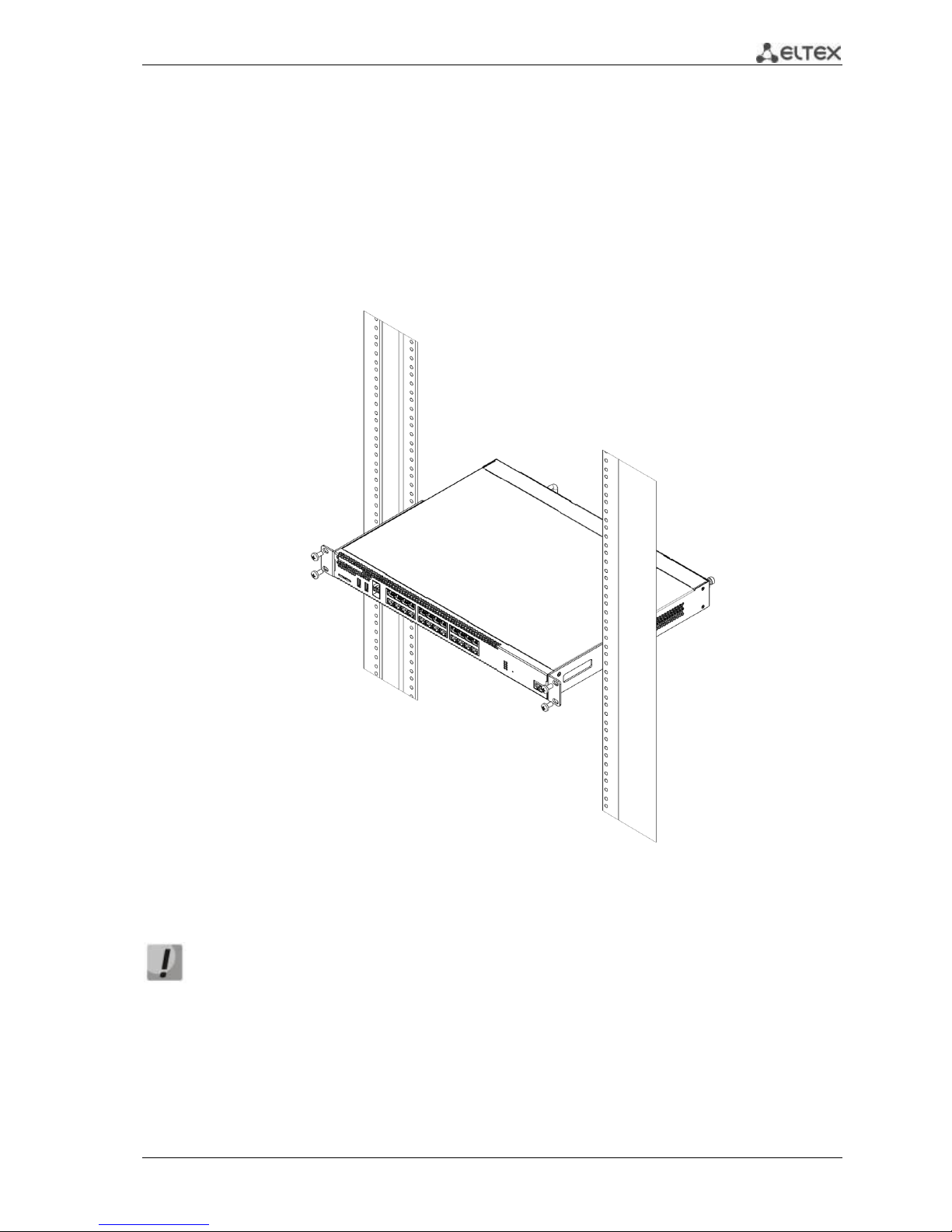
3.2 Device rack installation
To install the device to the rack:
1. Attach the device to the vertical guides of the rack.
2. Align mounting holes in the support bracket with the corresponding holes in the rack
guides. Use the holes of the same level on both sides of the guides to ensure the device
horizontal installation.
3. Use a screwdriver to screw the router to the rack.
Fig. 3.2 —Device rack installation
Device ventilation system is implemented using 'front-rear' layout. Vents are located on
the front and side panels of the device; ventilation modules are located at the rear. Do
not block air inlet and outlet vents to avoid components overheating and subsequent
device malfunction.
Page 24
24 ESR Series Routers Operation Manual
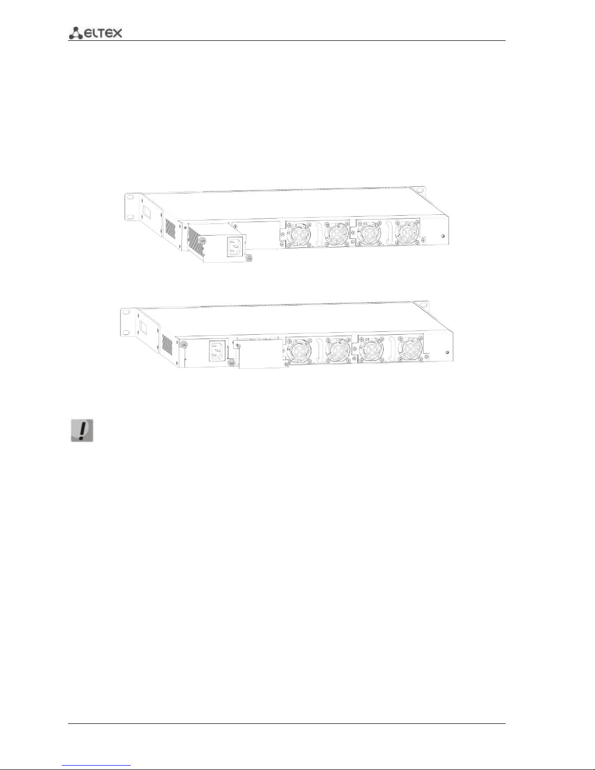
3.3 ESR-1000, ESR-1200 power module installation
ESR-1000 router can operate with one or two power modules. The second power module
installation is necessary when the device operates under strict reliability requirements.
From the electric point of view, both places for power module installation are identical. In the
context of device operation, the power module located closer to the edge is considered as the main
module, and the one closer to the centre—as the backup module. Power modules can be inserted and
removed without powering the device off. When additional power module is inserted or removed, the
router continues operation without reboot.
Fig. 3.3 —Power module installation
Fig. 3.4 —Cover installation
Power module fault indication may be caused not only by the module failure, but also by
the absence of the primary power supply.
You can check the state of power modules by the indication on the front panel of the router (see
Section 2.4.3) or by diagnostics, available through the router management interfaces.
3.4 Connection to Power Supply
1. Ground the case of the device prior to connecting it to the power supply. An insulated
multiconductor wire should be used for earthing. The device grounding and the earthing
wire cross-section should comply with Electric Installation Code.
2. If a PC or another device is supposed to be connected to the router console port, the device
should be also securely grounded.
3. Connect the power supply cable to the device. Depending on the delivery package, the
device can be powered by AC or DC electrical network. To connect the device to AC power
supply, use the cable from the delivery package. To connect the device to DC power supply,
use the cable with cross-section not less than 1mm2.
4. Turn the device on and check the front panel LEDs to make sure the terminal is in normal
operating conditions.
Page 25
ESR Series Routers Operation Manual 25
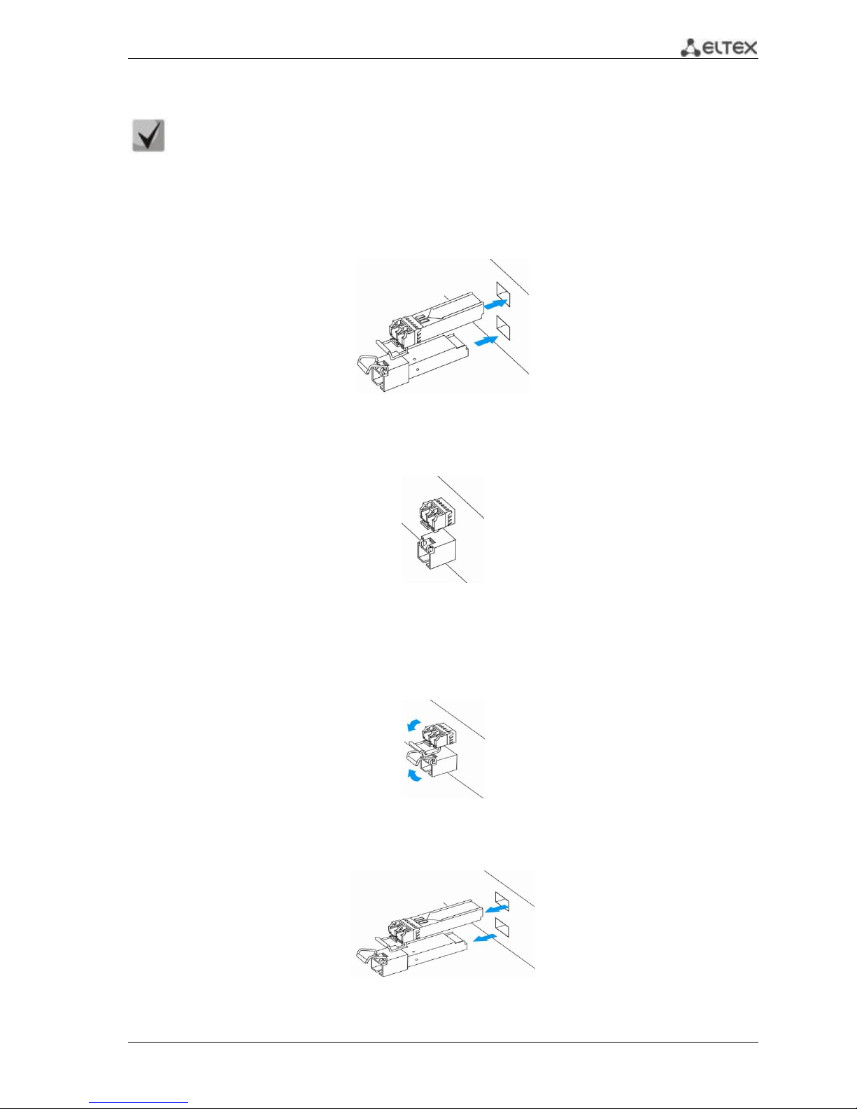
3.5 SFP transceiver installation and removal
Optical modules can be installed when the terminal is turned on or off.
Transceiver installation
1. Insert the top SFP module into a slot with its open side down, and the bottom SFP module with its
open side up.
Fig. 3.5 —SFP transceiver installation
2. Push the module into the device housing until the it is secured with a clicking sound.
Fig. 3.6 —Installed SFP transceivers
Transceiver removal
1. Flip the module handle to unlock the latch.
Fig. 3.7 —Opening the Latch of SFP Transceivers
2. Remove the module from the slot.
Fig. 3.8 —SFP transceiver removal
Page 26

26 ESR Series Routers Operation Manual
4 MANAGEMENT INTERFACES
You may use various management interfaces in order to control and monitor the device.
To access the device, you may use network connection via Telnet or SSH as well as direct
connection via RS-232 compliant console port. For Telnet, SSH or console port connections, the command
line interface is used for device management.
Factory settings contain trusted zone description and IP address for device management
access—192.168.1.1/24.
Trusted zone includes the following interfaces:
For ESR-100: GigabitEthernet 1/0/2-4;
For ESR-200: GigabitEthernet 1/0/2-8;
For ESR-1000: GigabitEthernet 1/0/2-24;
For ESR-1200: GigabitEthernet 1/0/2-16, TengigabitEthernet 1/0/3-8
By default, the user 'admin' with the password 'password' is defined in factory settings.
For each management interface provided, there are unified configuration operating principles.
When modifying and applying the configuration, you should follow the specific sequence described herein
that is intended to protect the device from misconfiguration.
4.1 Command line interface (CLI)
Command Line Interface (CLI) allows to perform the device management and monitor its operation
and status. You will require the PC application supporting Telnet or SSH protocol operation or direct
connection via the console port (e.g. HyperTerminal).
Command line interface enables user authorization and restricts access to commands depending on
their access level, provided by the administrator.
You can create as many users as you like, access rights will be assigned individually to each user.
To ensure command line interface security, all commands are divided into 2 categories—privileged
and unprivileged. Privileged commands basically include configuration commands. Unprivileged
commands include monitoring commands.
The system allows multiple users to connect to the device simultaneously.
Page 27

ESR Series Routers Operation Manual 27
5 INITIAL ROUTER CONFIGURATION
5.1 ESR router factory settings
The device is shipped to the consumer with the factory configuration installed which includes
essential basic settings. Factory configuration allows you to use the router as a gateway with SNAT
without applying any additional settings. Also, factory configuration contains settings that allow you to
obtain network access to the device for advanced configuration.
Description of factory settings
To establish network connection, the configuration features 2 security zones named 'Trusted' for
local area network and 'Untrusted' for public network. All interfaces are divided between two security
zones:
1. 'Untrusted' zone is meant for a public network (WAN) connection. In this zone, DHCP ports are
open in order to obtain dynamic IP address from the provider. All incoming connections from this zone to
the router are blocked.
This security zone includes the following interfaces:
For ESR-100 and ESR-200: GigabitEthernet 1/0/1;
For ESR-1000 and ESR-1200: GigabitEthernet1/0/1, TengigabitEthernet1/0/1,
TengigabitEthernet1/0/2.
Zone interfaces are grouped into a single L2 segment via Bridge 2 network bridge.
2. 'Trusted' zone is meant for a local area network (LAN) connection. In this zone, the following
ports are open: Telnet and SSH ports for remote access, ICMP ports for router availability test, DHCP ports
for clients obtaining IP addresses from the router. Outgoing connections from this zone into the Untrusted
zone are allowed.
This security zone includes the following interfaces:
For ESR-100: GigabitEthernet 1/0/2-4;
For ESR-200: GigabitEthernet1/0/2-8;
For ESR-1000: GigabitEthernet1/0/2-24;
For ESR-1200: GigabitEthernet1/0/2-16, TengigabitEthernet1/0/3-8;
Zone interfaces are grouped into a single L2 segment via Bridge 1 network bridge.
On the Bridge 2 interface, DHCP client is enabled to obtain dynamic IP address from the provider.
On Bridge 1 interface, static IP address 192.168.1.1/24 is configured. Created IP address acts as a gateway
for LAN clients. For LAN clients, DHCP address pool 192.168.1.2-192.168.1.254 is configured with the mask
255.255.255.0. For clients in order to access the Internet, the router should have Source NAT service
enabled.
Page 28

28 ESR Series Routers Operation Manual
Security zone policies have the following configuration:
Table 5.1 —Security zone policy description
Traffic origin zone
Traffic destination
zone
Traffic type
Action
Trusted
Untrusted
TCP, UDP, ICMP
enabled
Trusted
Trusted
TCP, UDP, ICMP
enabled
Trusted
self
TCP/23(Telnet), TCP/22(SSH), ICMP,
UDP/67(DHCP Server), UDP/123(NTP)
enabled
Untrusted
self
UDP/68(DHCP Client),
enabled
To enable device configuration on the first startup, 'admin' account has been created in the
router configuration. We strongly recommend to change administrator password during the
initial configuration of the router.
To enable network access to the router on the first startup, static IP address 192.168.1.1/24
has been configured on Bridge 1 interface.
5.2 Router connection and configuration
ESR series routers are intended to perform border gateway functions and securing the user network
when it is connected to public data networks.
Basic router configuration should include:
Assigning IP addresses (static or dynamic) to the interfaces that participate in data routing
Creation of security zones and distribution of interfaces between these zones
Creation of policies governing data transfer through these zones
Configuration of services that accompany the data routing (NAT, Firewall, etc.)
Advanced settings depend on the requirements of the specific device application pattern and may
be easily added or modified with the existing management interfaces.
5.2.1 Connection to the router
There are several device connection options:
5.2.1.1 Ethernet LAN connection
Upon the initial startup, the router starts with the factory configuration. For factory
configuration description, see Section 5.1 of this Manual.
Connect the network data cable (patch cord) to any port within the 'Trusted' zone and to the PC
intended for management tasks.
In the router factory configuration, DHCP server is enabled with IP address pool in 192.168.1.0/24
subnet.
When network interface is connected to the management computer, the latter should obtain the
network address from the server.
Page 29

ESR Series Routers Operation Manual 29
If IP address is not obtained for some reason, assign the interface address manually using any
address except for 192.168.1.1 in 192.168.1.0/24 subnet.
5.2.1.2 RS-232 console port connection
Using RJ-45/DBF9 cable included into device delivery package, connect the router 'Console' port to
the computer RS-232 port.
Launch terminal application (e.g. HyperTerminal or Minicom) and create a new connection. VT100
terminal emulation mode should be used.
Specify the following settings for RS-232 interface:
Bit rate: 115200bps
Data bits: 8bit
Parity: no
Stop bits: 1
Flow control: none
5.2.2 Basic router configuration
Upon the first startup, the router configuration procedure includes the following steps:
Changing password for "admin" user.
Creation of new users.
Assigning device name (Hostname).
Setting parameters for public network connection in accordance with the provider
requirements.
Configuring remote connection to router.
Applying basic settings.
5.2.2.1 Changing password for "admin" user
To ensure the secure system access, you should change the password for the privileged 'admin'
user.
'techsupport' account ('eltex' up to version 1.0.7) is required for service center specialist
remote access.
'remote' account — RADIUS, TACACS+, LDAP authentication.
'admin', 'techsupport', 'remote' users cannot be deleted. You may only change passwords
and a privilege level.
Username and password are required for login during the device administration sessions.
To change 'admin' password, use the following commands:
esr# configure
esr(config)# username admin
esr(config-user)# password <new-password>
esr(config-user)# exit
Page 30

30 ESR Series Routers Operation Manual
5.2.2.2 Creation of new users
Use the following commands to create a new system user or configure the username, password, or
privilege level:
esr(config)# username <name>
esr(config-user)# password <password>
esr(config-user)# privilege <privilege>
esr(config-user)# exit
Privilege levels 1–9 allow you to access the device and view its operation status, but the
device configuration is disabled. Privilege levels 10–14 allow both the access to the device
and configuration of majority of its functions. Privilege level 15 allows both the access to
the device and configuration of all its functions.
Example of commands, that allow you to create user 'fedor' with password '12345678' and privilege
level 15 and create user 'ivan' with password 'password' and privilege level '1:'
esr# configure
esr(config)# username fedor
esr(config-user)# password 12345678
esr(config-user)# privilege 15
esr(config-user)# exit
esr(config)# username ivan
esr(config-user)# password password
esr(config-user)# privilege 1
esr(config-user)# exit
5.2.2.3 Assigning device name
To assign the device name, use the following commands:
esr# configure
esr(config)# hostname <new-name>
When a new configuration is applied, command prompt will change to the value specified by <new-name>
parameter.
5.2.2.4 Configuration of public network parameters
To configure router network interface in the public network, you should assign parameters defined by the
network provider—default IP address, subnet mask and gateway address—to the device.
Example of static IP address configuration commands for GigabitEthernet 1/0/2.150 sub-interface
used for obtaining access to the router via VLAN 150.
Interface parameters:
IP address: 192.168.16.144;
Subnet mask: 255.255.255.0;
Default gateway IP address: 192.168.16.1.
esr# configure
esr(config)# interface gigabitethernet 1/0/2.150
esr(config-subif)# ip address 192.168.16.144/24
esr(config-subif)# exit
esr(config)# ip route 0.0.0.0/0 192.168.16.1
Page 31

ESR Series Routers Operation Manual 31
To ensure the correct IP address assigning for the interface, enter the following command when the
configuration is applied:
esr# show ip interfaces
IP address Interface Type
------------------- --------------------------------- -------
192.168.16.144/24 gigabitethernet 1/0/2.150 static
Provider may use dynamically assigned addresses in their network. If the there is DHCP server in the
network, you can obtain the IP address via DHCP protocol.
Configuration example for obtaining dynamic IP address from DHCP server on GigabitEthernet
1/0/10 interface:
esr# configure
esr(config)# interface gigabitethernet 1/0/10
esr(config-if)# ip address dhcp enable
esr(config-if)# exit
To ensure the correct IP address assigning for the interface, enter the following command when the
configuration is applied:
esr# show ip interfaces
IP address Interface Type
------------------- --------------------------------- -------
192.168.11.5/25 gigabitethernet 1/0/10 DHCP
5.2.2.5 Configuring remote connection to router
In the factory configuration, remote access to the router may be established via Telnet or SSH from
the 'trusted' zone. To enable remote access to the router from other zones, e.g. from the public network,
you should create the respective rules in the firewall.
When configuring access to the router, rules should be created for the following pair of zones:
source-zone—zone that the remote access will originate from
self—zone which includes router management interface
Use the following commands to create the allowing rule:
esr# configure
esr(config)# security zone-pair <source-zone> self
esr(config-zone-pair)# rule <number>
esr(config-zone-rule)# action permit
esr(config-zone-rule)# match protocol tcp
esr(config-zone-rule)# match source-address <network object-group>
esr(config-zone-rule)# match destination-address <network object-group>
esr(config-zone-rule)# match source-port any
esr(config-zone-rule)# match destination-port <service object-group>
esr(config-zone-rule)# enable
esr(config-zone-rule)# exit
esr(config-zone-pair)# exit
Example of commands that allow users from 'untrusted' zone with IP addresses in range 132.16.0.5-
132.16.0.10 to connect to the router with IP address 40.13.1.22 via SSH:
Page 32

32 ESR Series Routers Operation Manual
esr# configure
esr(config)# object-group network clients
esr(config-addr-set)# ip address-range 132.16.0.5-132.16.0.10
esr(config-addr-set)# exit
esr(config)# object-group network gateway
esr(config-addr-set)# ip address-range 40.13.1.22
esr(config-addr-set)# exit
esr(config)# object-group service ssh
esr(config-port-set)# port-range 22
esr(config-port-set)# exit
esr(config)# security zone-pair untrusted self
esr(config-zone-pair)# rule 10
esr(config-zone-rule)# action permit
esr(config-zone-rule)# match protocol tcp
esr(config-zone-rule)# match source-address clients
esr(config-zone-rule)# match destination-address gateway
esr(config-zone-rule)# match source-port any
esr(config-zone-rule)# match destination-port ssh
esr(config-zone-rule)# enable
esr(config-zone-rule)# exit
esr(config-zone-pair)# exit
5.2.2.6 Applying basic settings
To apply performed router configuration changes, you should enter the following commands from
the root section of the command interface.
esr# commit
esr# confirm
If during configuration device was accessed remotely and the management interface network
settings have changed, when you execute commit command the connection to the device may be lost.
Use new network settings defined in configuration to connect to the device and execute confirm
command.
If you are not able to execute confirm command, upon the expiration of the confirmation timer
device configuration will revert to the state prior the commit command execution.
Page 33

ESR Series Routers Operation Manual 33
6 FIRMWARE UPDATE
6.1 Updating firmware via system resources
To update the firmware, use any of the following servers: TFTP, FTP, SCP. Router firmware
files obtained from the manufacturer should be allocated on the server.
The router stores two copies of the firmware. To ensure the reliability of the firmware
update procedure, only the copy that was not used for the last device startup is available
for the update.
Update via system resources is available in version 1.0.3.69 and later. You may update the
firmware from the earlier versions using the instructions located in Section 6.2.
To update the firmware for the device running the operating system, follow procedure described
below.
1. Prepare the selected server for operation. You should know the server address; also firmware
distributive file should be loaded onto the server.
2. The router should be prepared for operation according to the documentary requirements.
Router configuration should allow for data exchange with the server via TFTP/FTP/SCP and
ICMP protocols. At that, you should take into account the server inherence to the router
security zones.
3. Connect to the router locally via Console port or remotely via Telnet or SSH.
Check the server availability for the router using ping command on the router. If the server is
not available, check the router settings and the status of the server network interfaces.
4. To update the router firmware, enter the following command. Specify IP address of the server
being used as <server> parameter. For updates that utilize FTP or SCP server, you should enter a
username (<user> parameter) and a password (<password> parameter). Specify the name of
the firmware file loaded onto the server as <file_name> parameter. When the command is
executed, router will copy the file into its internal memory, perform data integrity check and
save it into non-volatile memory.
TFTP:
esr# copy tftp://<server>:/<file_name> system:firmware
FTP:
esr# copy ftp://[<user>[:<password>]@]<server>:/<file_name>
system:firmware
SCP:
esr# сору scp://[<user>[:<password>]@]<server>://<folder>/<file_name>
system:firmware
For example, let's update basic firmware via SCP:
esr# сору scp://adm:password123@192.168.16.168://home/tftp/firmware
system:firmware
5. To start the device with the new firmware version, you have to switch the active image. With
show bootvar command, locate the image number, containing updated firmware.
Page 34

34 ESR Series Routers Operation Manual
esr# show bootvar
Image Version Date Status After reboot
----- ------------------------- -------------------- ------------ ------------
1 1.0.4 build 94[f812808] date 18/02/2015 time Active *
16:12:54
2 1.0.4 build 94[f812808] date 18/02/2015 time Not Active
16:12:54
Use the following command to select the image:
esr# boot system image-[1|2]
6. To update the secondary bootloader (U-Boot), enter the following command: Specify IP address
of the server being used as <server> parameter. For updates that utilize FTP or SCP server, you
should enter a username (<user> parameter) and a password (<password> parameter). Specify
the name of the secondary bootloader onto the server as <file_name> parameter. When the
command is executed, router will copy the file into its internal memory, perform data integrity
check and save it into non-volatile memory.
TFTP:
esr# copy tftp://<server>:/<file_name> system:boot
FTP:
esr# copy ftp://<server>:/<file_name> system:boot
SCP:
esr# copy scp://[<user>[:<password>]@]<server>://<folder>/<file_name>
system:boot
6.2 Updating firmware via bootloader
Router firmware may be updated via the bootloader as follows:
1. When U-Boot finishes the router initialization, break the device startup with the <Esc> key.
Configuring PoE...
distribution 1 dest_threshold 0xa drop_timer 0x0
Configuring POE in bypass mode
NAE configuration done!
initializing port 0, type 2.
initializing port 1, type 2.
SMC Endian Test:b81fb81f
nae-0, nae-1
=======Skip: Load SYS UCORE for old 8xxB1/3xxB0 revision on default.
Hit any key to stop autoboot: 2
2. Specify TFTP server address:
BRCM.XLP316Lite Rev B0.u-boot# setenv serverip 10.100.100.1
3. Specify router IP address:
BRCM.XLP316Lite Rev B0.u-boot# setenv ipaddr 10.100.100.2
4. You may save the environment using 'saveenv' command for future updates.
5. Launch firmware update procedure:
BRCM.XLP316Lite Rev B0.u-boot# run tftp_update_image1
BRCM.XLP316Lite Rev B0.u-boot# run set_bootpart_1
Page 35

ESR Series Routers Operation Manual 35
Using nae-0-3 device
TFTP from server 10.100.100.1; our IP address is 10.100.100.2
Filename 'esr1000/firmware'.
Load address: 0xa800000060000000
Loading: TftpStart:TftpTimeoutMsecs = 10000, TftpTimeoutCountMax = 6
#################################################################
#################################################################
#################################################################
#########################
####################################
done
Bytes transferred = 64453909 (3d77d15 hex)
Device 0: MT29F8G08ABBCAH4 ... is now current device
NAND erase: device 0 offset 0x1440000, size 0x6400000
Bad block table found at page 262080, version 0x01
Bad block table found at page 262016, version 0x01
Erasing at 0x7800000 -- 1895825408% complete..
OK
NAND write: device 0 offset 0x1440000, size 0x6400000
104857600 bytes written: OK
6. Run the downloaded software:
BRCM.XLP316Lite Rev B0.u-boot# reset
6.3 Secondary bootloader update (U-Boot)
Secondary bootloader initializes NAND and the router. During the update, a new file of the
secondary bootloader is saved to the flash
To view the current version of the load file operating on the device, execute 'version' command in
U-Boot CLI. Also, the version is displayed during the router startup.:
BRCM.XLP316Lite Rev B0.u-boot# version
BRCM.XLP.U-Boot:1.1.0.47 (29/11/2016 - 19:00:24)
Firmware update procedure:
1. When U-Boot finishes the router initialization, break the device startup with the <Esc> key.
Configuring PoE...
distribution 1 dest_threshold 0xa drop_timer 0x0
Configuring POE in bypass mode
NAE configuration done!
initializing port 0, type 2.
initializing port 1, type 2.
SMC Endian Test:b81fb81f
nae-0, nae-1
=======Skip: Load SYS UCORE for old 8xxB1/3xxB0 revision on default.
Hit any key to stop autoboot: 2
2. Specify TFTP server address:
BRCM.XLP316Lite Rev B0.u-boot# setenv serverip 10.100.100.1
3. Specify router IP address:
BRCM.XLP316Lite Rev B0.u-boot# setenv ipaddr 10.100.100.2
4. You may save the environment using 'saveenv' command for future updates.
Page 36

36 ESR Series Routers Operation Manual
5. Launch firmware update procedure:
BRCM.XLP316Lite Rev B0.u-boot# run upd_uboot (or «run tftp_update_uboot» - depends
on the bootloader version)
Using nae-1 device
TFTP from server 10.100.100.1; our IP address is 10.100.100.2
Filename 'esr1000/u-boot.bin'.
Load address: 0xa800000078020000
Loading: ###########################################################
done
Bytes transferred = 852648 (d02a8 hex)
SF: Detected MX25L12805D with page size 256, total 16777216 bytes
16384 KiB MX25L12805D at 0:0 is now current device
6. Reboot the router:
BRCM.XLP316Lite Rev B0.u-boot# reset
Page 37

ESR Series Routers Operation Manual 37
7 ROUTER CONFIGURATION EXAMPLES
7.1 VLAN Configuration
VLAN (Virtual Local Area Network) is a logical (virtual) local area network that represents a group of
devices which communicate on channel level regardless of their physical location.
Objective 1: On the basis of the factory configuration, remove gi1/0/1 port from VLAN 2.
Fig. 7.1 —Network structure
Solution:
Remove VLAN2 from gi1/0/1 port:
esr-1000(config)# interface gi 1/0/1
esr-1000(config-if-gi)# switchport general allowed vlan remove 2 untagged
esr-1000(config-if-gi)# no switchport general pvid
Configuration changes will take effect when the configuration is applied:
esr-1000# commit
Configuration has been successfully committed
esr-1000# confirm
Configuration has been successfully confirmed
Objective 2: Configure gi1/0/1 and gi1/0/2 ports for packet transmission and reception in VLAN 2,
VLAN 64, VLAN 2000.
Fig. 7.2 —Network structure
Solution:
Create VLAN 2, VLAN 64, VLAN 2000 on ESR-1000:
esr-1000(config)# vlan 2,64,2000
Specify VLAN 2, VLAN 64, VLAN 2000 for gi1/0/1-2 port:
Page 38

38 ESR Series Routers Operation Manual
esr-1000(config)# interface gi1/0/1
esr-1000(config-if-gi)# switchport forbidden default-vlan
esr-1000(config-if-gi)# switchport general allowed vlan add 2,64,2000 tagged
Configuration changes will take effect when the configuration is applied:
esr-1000# commit
Configuration has been successfully committed
esr-1000# confirm
Objective 3: Configure gi1/0/1 ports for packet transmission and reception in VLAN 2, VLAN 64,
VLAN 2000 in trunk mode, configure gi1/0/2 port in access mode for VLAN 2 on ESR-100/ESR -200.
Fig. 7.3—Network structure
Solution:
Create VLAN 2, VLAN 64, VLAN 2000 on ESR-100/ ESR-200:
esr(config)# vlan 2,64,2000
Specify VLAN 2, VLAN 64, VLAN 2000 for gi1/0/1 port:
esr(config)# interface gi1/0/1
esr(config-if-gi)# switchport forbidden default-vlan
esr(config-if-gi)# switchport mode trunk
esr(config-if-gi)# switchport trunk allowed vlan add 2,64,2000
Specify VLAN2 to gi1/0/2 port:
esr(config)# interface gi1/0/1
esr(config-if-gi)# switchport access vlan 2
Configuration changes will take effect when the configuration is applied:
esr# commit
Configuration has been successfully committed
esr# confirm
Page 39

ESR Series Routers Operation Manual 39
7.2 QinQ termination configuration
QinQ is a technology of packet transmission with two 802.1q tags. The technology is used for
extending quantity of VLANs in data networks. 802.1q header, which is closer to payload, is an Inner Tag
also known as C-VLAN (Custimer VLAN). 802.1q header, which is comes before C-VLAN, is an Outer Tag
also known as S-VLAN (Service VLAN). Using of double tags in Ethernet frames is describing by 802.1ad
protocol.
Objective: Configure 192.168.1.1/24 subnet termination (Combinations C-VLAN: 741, S-VLAN: 828)
on gigabitethernet 1/0/1 physical interface.
Solution:
Enable 802.1ad protocol support on physical interface:
esr(config)# interface gigabitethernet 1/0/1
esr(config-if-gi)# switchport dot1q ethertype egress stag 802.1ad
esr(config-if-gi)# exit
Create subinterface for S-VLAN: 828
esr(config)# interface gigabitethernet 1/0/1.828
esr(config-subif)# exit
Create QinQ subinterface for C-VLAN: 741
esr(config)# interface gigabitethernet 1/0/1.828.741
esr(config-qinq-if)# ip address 192.168.1.1/24
esr(config-qinq-if)# exit
Configuration changes will take effect when the configuration is applied:
esr-1000# commit
Configuration has been successfully committed
esr-1000# confirm
Configuration has been successfully confirmed
Besides assigning IP address, it is necessary to disable firewall or to configure
corresponding security zone on qinq interface.
7.3 AAA configuration
AAA (Authentication, Authorization, Accounting) is used for description of access provisioning and
control.
Authentication is a matching of a person (request) for the existing account in the security
system. Performed by the login and password.
Authorization (authorization, privilege verification, access level verification) is a matching of
the existing account in the system (passed authentication) and specific privileges.
Accounting (accounting)is a monitoring of user connection or changes made by the user.
Objective: Configure authentication for users being connected via Telnet and RADIUS
(192.168.16.1/24).
Page 40

40 ESR Series Routers Operation Manual
Solution:
Configure connection to RADIUS server and specify the key (password):
esr# configure
esr(config)# radius-server host 192.168.16.1
esr(config-radius-server)# key ascii-text encrypted 8CB5107EA7005AFF
esr(config-radius-server)# exit
Create authentication profile:
esr(config)# aaa authentication login log radius
Specify authentication mode used for Telnet protocol connection:
esr(config)# line telnet
esr(config-line-telnet)# login authentication log
esr(config-line-telnet)# exit
esr(config)# exit
Configuration changes will take effect when the configuration is applied:
esr# commit
Configuration has been successfully committed
esr# confirm
Configuration has been successfully confirmed
esr#
To view the information on RADIUS server connection settings, use the following command:
esr# show aaa radius-servers
To view the authentication profiles, use the following command:
esr# show aaa authentication
7.4 Command privilege configuration
Command privilege configuration is a flexible tool that allows you to assign baseline user privilege
level (1–15) to a command set. In future, you may specify privilege level during user creation which will
define a command set available to them.
Levels 1-9 enable all monitoring commands (show …).
Levels 10-14 enable all commands except for device reboot, user management and other
specific commands.
Level 15 enables all monitoring commands.
Objective: Transfer all interface information display commands to the privilege level 10 except for
'show interfaces bridges' command. Transfer 'show interfaces bridges' command to the privilege level 3.
Solution:
In configuration mode, identify commands enabled for operation under privilege level 10 and
privilege level 3.
Page 41

ESR Series Routers Operation Manual 41
esr(config)# privilege root level 3 "show interfaces bridge"
esr(config)# privilege root level 10 "show interfaces"
Configuration changes will take effect when the configuration is applied and only for new user
sessions:
esr# commit
Configuration has been successfully committed
esr# confirm
Configuration has been successfully confirmed
esr#
7.5 DHCP server configuration
Integrated DHCP server of the router allows you to configure LAN device network settings. Router
DHCP server is able to send additional options to network devices, for example:
default-router—IP address of the router used as default gateway.
domain-name—domain name which will be used by client while solving host names via
domain name system (DNS).
dns-server—list of domain name server addresses for the current network that should be
known by the client. Server addresses are listed in descending order of their preference.
Objective: Configure DHCP server operation in a local network that belongs to the 'trusted' security
zone. Define IP address pool from 192.168.1.0/24 subnet for distribution to clients. Define address lease
time equal to 1 day. Configure transmission of the default route, domain name and DNS server addresses
to clients using DHCP options.
Solution:
Create 'trusted' security zone and define the inherence of the network interfaces being used to
zones:
esr# configure
esr(config)# security zone trusted
esr(config-zone)# exit
esr(config)# interface gi1/0/2-24
esr(config-if-gi)# security-zone TRUSTED
esr(config-if-gi)# exit
Create address pool named 'Simple' and add IP address range intended for server clients lease into
this pool. Define parameters of the subnet that the pool belongs to, and the lease time for addresses.
esr# configure
esr(config)# ip dhcp-server pool Simple
esr(config-dhcp-server)# network 192.168.1.0/24
esr(config-dhcp-server)# address-range 192.168.1.100-192.168.1.125
esr(config-dhcp-server)# default-lease-time 1:00:00
Configure transfer of additional network parameters to clients:
default route: 192.168.1.1
domain name: eltex.loc
DNS server list: DNS1: 172.16.0.1, DNS2: 8.8.8.8.
esr(config-dhcp-server)# domain-name "eltex.loc"
esr(config-dhcp-server)# default-router 192.168.1.1
esr(config-dhcp-server)# dns-server 172.16.0.1 8.8.8.8
Page 42

42 ESR Series Routers Operation Manual
esr(config-dhcp-server)# exit
To enable IP address distribution from the configurable pool by DHCP server, IP interface should be
created on the router that belongs to the same subnet as the pool addresses.
esr(config)# interface gigabitethernet 1/0/1
esr(config-if-gi)# security-zone trusted
esr(config-if-gi)# ip address 192.168.1.1/24
esr(config-if-gi)# exit
To enable DHCP protocol message transmission to the server, you should create the respective port
profiles including source port 68 and destination port 67 used by DHCP protocol and create the allowing
rule in the security policy for UDP protocol packet transmission.
esr(config)# object-group service dhcp_server
esr(config-object-group-service)# port-range 67
esr(config-object-group-service)# exit
esr(config)# object-group service dhcp_client
esr(config-object-group-service)# port-range 68
esr(config-object-group-service)# exit
esr(config)# security zone-pair trusted self
esr(config-zone-pair)# rule 30
esr(config-zone-rule)# match protocol udp
esr(config-zone-rule)# match source-address any
esr(config-zone-rule)# match destination-address any
esr(config-zone-rule)# match source-port dhcp_client
esr(config-zone-rule)# match destination-port dhcp_server
esr(config-zone-rule)# action permit
esr(config-zone-rule)# enable
esr(config-zone-rule)# exit
esr(config-zone-pair)# exit
Allow server operation:
esr(config)# ip dhcp-server
esr(config)# exit
Configuration changes will take effect when the configuration is applied:
esr# commit
Configuration has been successfully committed
esr# confirm
Configuration has been successfully confirmed
esr#
To view the list of leased addresses, use the following command:
esr# show ip dhcp binding
To view the configured address pools, use the following command:
esr# show ip dhcp server pool
esr# show ip dhcp server pool Simple
Configuration of settings for IPv6 is performed by analogy to IPv4.
Page 43

ESR Series Routers Operation Manual 43
7.6 Destination NAT configuration
Destination NAT (DNAT) function includes destination IP address translation for packets transferred
through the network gateway.
DNAT is used for redirection of traffic, coming to a specific 'virtual' address in a public network, to a
'real' server in LAN located behind the network gateway. This function may be used for establishing a
public access to servers located within the private network without any public network address.
Objective: Establish access from the public network, that belongs to the 'UNTRUST' zone, to LAN
server in 'TRUST' zone. Server address in LAN—10.1.1.100. Server should be accessible from outside the
network—address 1.2.3.4, access port 80.
Fig. 7.4—Network structure
Solution:
Create 'UNTRUST' and 'TRUST' security zones. Define the inherence of the network interfaces being
used to zones. Assign IP addresses to interfaces simultaneously.
esr# configure
esr(config)# security zone UNTRUST
esr(config-zone)# exit
esr(config)# security zone TRUST
esr(config-zone)# exit
esr(config)# interface gigabitethernet 1/0/1
esr(config-if-gi)# security-zone TRUST
esr(config-if-gi)# ip address 10.1.1.1/25
esr(config-if-gi)# exit
esr(config)# interface tengigabitethernet 1/0/1
esr(config-if-te)# ip address 1.2.3.4/29
esr(config-if-te)# security-zone UNTRUST
esr(config-if-te)# exit
Create IP address and port profiles required for configuration of the Firewall and DNAT rules.
NET_UPLINK—public network address profile
SERVER_IP—local area network address profile
SRV_HTTP—port profile
esr(config)# object-group network NET_UPLINK
esr(config-object-group-network)# ip address 1.2.3.4
esr(config-object-group-network)# exit
esr(config)# object-group service SRV_HTTP
esr(config-object-group-network)# port 80
esr(config-object-group-network)# exit
esr(config)# object-group network SERVER_IP
esr(config-object-group-network)# ip address 10.1.1.100
esr(config-object-group-network)# exit
Page 44

44 ESR Series Routers Operation Manual
Proceed to DNAT configuration mode and create destination address and port pool that will be used
for translation of packet addresses coming to address 1.2.3.4 from the external network.
esr(config)# nat destination
esr(config-dnat)# pool SERVER_POOL
esr(config-dnat-pool)# ip address 10.1.1.100
esr(config-dnat-pool)# ip port 80
esr(config-dnat-pool)# exit
Create 'DNAT' rule set which will be used for address translation. In the set attributes, specify that
the rules are applying only to packets coming from the 'UNTRUST' zone. Rule set includes data matching
requirements for destination address and port (match destination-address, match destination-port) and
for the protocol. Also, the set includes an action that applies to the data that satisfy all of the rules (action
destination-nat). The rule set is applied with 'enable' command.
esr(config-dnat)# ruleset DNAT
esr(config-dnat-ruleset)# from zone UNTRUST
esr(config-dnat-ruleset)# rule 1
esr(config-dnat-rule)# match destination-address NET_UPLINK
esr(config-dnat-rule)# match protocol tcp
esr(config-dnat-rule)# match destination-port SERV_HTTP
esr(config-dnat-rule)# action destination-nat pool SERVER_POOL
esr(config-dnat-rule)# enable
esr(config-dnat-rule)# exit
esr(config-dnat-ruleset)# exit
esr(config-dnat)# exit
To transfer the traffic coming from 'UNTRUST' zone into 'TRUST' zone, create the respective pair of
zones. Only DNAT-translated traffic with the destination address matching the 'SERVER_IP' specified in the
profile should be transferred.
esr(config)# security zone-pair UNTRUST TRUST
esr(config-zone-pair)# rule 1
esr(config-zone-rule)# match source-address any
esr(config-zone-rule)# match destination-address SERVER_IP
esr(config-zone-rule)# match protocol any
esr(config-zone-rule)# match destination-nat
esr(config-zone-rule)# action permit
esr(config-zone-rule)# enable
esr(config-zone-rule)# exit
esr(config-zone-pair)# exit
esr(config)# exit
Configuration changes will take effect when the configuration is applied:
esr# commit
Configuration has been successfully committed
esr# confirm
Configuration has been successfully confirmed
To view the performed settings, use the following command:
esr# show ip nat destination pools
esr# show ip nat destination rulesets
esr# show ip nat proxy-arp
esr# show ip nat translations
Page 45

ESR Series Routers Operation Manual 45
7.7 Source NAT configuration
Source NAT (SNAT) function substitutes source address for packets transferred through the network
gateway. When packets are transferred from LAN into public network, source address is substituted to
one of the gateway public addresses. Additionally, source port substitution may be added to the source
address. When packets are transferred back from public network to LAN, address and port are reverted to
their original values.
SNAT function enables Internet access for computers located in LAN. At that, there is no need in
assigning public IP addresses for these computers.
Objective 1: Configure access for users in LAN 10.1.2.0/24 to public network using Source NAT
function. Define public network address range for SNAT 100.0.0.100-100.0.0.249.
Fig. 7.5—Network structure
Solution:
Begin configuration with creation of security zones, configuration of network interfaces and their
inherence to security zones. Create 'TRUST' zone for LAN and 'UNTRUST' zone for public network.
esr# configure
esr(config)# security zone UNTRUST
esr(config-zone)# exit
esr(config)# security zone TRUST
esr(config-zone)# exit
esr(config)# interface gigabitethernet 1/0/1
esr(config-if-gi)# ip address 10.1.2.1/24
esr(config-if-gi)# security-zone TRUST
esr(config-if-gi)# exit
esr(config)# interface tengigabitethernet 1/0/1
esr(config-if-te)# ip address 100.0.0.99/24
esr(config-if-te)# security-zone UNTRUST
esr(config-if-te)# exit
For SNAT function configuration and definition of rules for security zones, create 'LOCAL_NET' LAN
address profile that includes addresses which are allowed to access the public network and
'PUBLIC_POOL' public network address profile.
esr(config)# object-group network LOCAL_NET
esr(config-object-group-network)# ip address-range 10.1.2.2-10.1.2.254
esr(config-object-group-network)# exit
esr(config)# object-group network PUBLIC_POOL
esr(config-object-group-network)# ip address-range 100.0.0.100-100.0.0.249
esr(config-object-group-network)# exit
Page 46

46 ESR Series Routers Operation Manual
To transfer traffic from 'TRUST' zone into 'UNTRUST' zone, create a pair of zones and add rules
allowing traffic transfer in this direction. Additionally, there is a check in place to ensure that data source
address belongs to 'LOCAL_NET' address range in order to limit the access to public network. Rules are
applied with enable command.
esr(config)# security zone-pair TRUST UNTRUST
esr(config-zone-pair)# rule 1
esr(config-zone-rule)# match source-address LOCAL_NET
esr(config-zone-rule)# match destination-address any
esr(config-zone-rule)# match protocol any
esr(config-zone-rule)# action permit
esr(config-zone-rule)# enable
esr(config-zone-rule)# exit
esr(config-zone-pair)# exit
Configure SNAT service. First step is to create public network address pool for use with SNAT.
esr(config)# nat sourse
esr(config-snat)# pool TRANSLATE_ADDRESS
esr(config-snat-pool)# ip address-range 100.0.0.100-100.0.0.249
esr(config-snat-pool)# exit
Second step is to create SNAT rule set. In the set attributes, specify that the rules are applying only
to packets transferred to public network—into the 'UNTRUST' zone. Rules include a check which ensures
that data source address belongs to 'LOCAL_NET' pool.
esr(config-snat)# ruleset SNAT
esr(config-snat-ruleset)# to zone UNTRUST
esr(config-snat-ruleset)# rule 1
esr(config-snat-rule)# match source-address LOCAL_NET
esr(config-snat-rule)# match destination-address any
esr(config-snat-rule)# match destination-port any
esr(config-snat-rule)# action source-nat pool TRANSLATE_ADDRESS
esr(config-snat-rule)# enable
esr(config-snat-rule)# exit
esr(config-snat-ruleset)# exit
In order the router could response to the ARP requests for addresses from the public pool, you
should launch ARP Proxy service. ARP Proxy service is configured on the interface that IP address from
'PUBLIC_POOL' public network address profile subnet belongs to.
esr(config)# interface tengigabitethernet 1/0/1
esr(config-if-te)# ip nat proxy-arp PUBLIC_POOL
To enable public network access for LAN devices, they should be configured for routing—10.1.2.1
should be defined as a gateway address.
On the router, you should create the route for public network. Define this route as a default using
the following command.
esr(config)# ip route 0.0.0.0/0 100.0.0.100
esr(config)# exit
Configuration changes will take effect when commit command is executed:
esr# commit
Configuration has been successfully committed
esr# confirm
Configuration has been successfully confirmed
Page 47

ESR Series Routers Operation Manual 47
Objective 2: Configure access for users in LAN 21.12.2.0/24 to public network using Source NAT
function without the firewall. Public network address range for SNAT 200.10.0.100-200.10.0.249.
Fig. 7.6—Network structure
Solution:
Begin configuration with network interface configuration and disabling the firewall:
esr(config)# interface gigabitethernet 1/0/1
esr(config-if-gi)# ip address 21.12.2.1/24
esr(config-if-gi)# ip firewall disable
esr(config-if-gi)# exit
esr(config)# interface tengigabitethernet 1/0/1
esr(config-if-te)# ip address 200.10.0.99/24
esr(config-if-te)# ip firewall disable
esr(config-if-te)# exit
For SNAT function configuration, create 'LOCAL_NET' LAN address profile that includes addresses
which are allowed to access the public network and 'PUBLIC_POOL' public network address profile.
esr(config)# object-group network LOCAL_NET
esr(config-object-group-network)# ip address-range 21.12.2.2-21.12.2.254
esr(config-object-group-network)# exit
esr(config)# object-group network PUBLIC_POOL
esr(config-object-group-network)# ip address-range 200.10.0.100-200.10.0.249
esr(config-object-group-network)# exit
Configure SNAT service.
First step is to create public network address pool for use with SNAT:
esr(config)# nat source
esr(config-snat)# pool TRANSLATE_ADDRESS
esr(config-snat-pool)# ip address-range 200.10.0.100-200.10.0.249
esr(config-snat-pool)# exit
Second step is to create SNAT rule set. In the set attributes, specify that the rules are applying only
to packets transferred to public network through te1/0/1 port. Rules include a check which ensures that
data source address belongs to 'LOCAL_NET' pool:
esr(config-snat)# ruleset SNAT
esr(config-snat-ruleset)# to interface te1/0/1
esr(config-snat-ruleset)# rule 1
esr(config-snat-rule)# match source-address LOCAL_NET
esr(config-snat-rule)# match destination-address any
esr(config-snat-rule)# match protocol any
esr(config-snat-rule)# action source-nat pool TRANSLATE_ADDRESS
esr(config-snat-rule)# enable
esr(config-snat-rule)# exit
esr(config-snat-ruleset)# exit
Page 48

48 ESR Series Routers Operation Manual
In order the router could response to the ARP requests for addresses from the public pool, you
should launch ARP Proxy service. ARP Proxy service is configured on the interface that IP address from
'PUBLIC_POOL' public network address profile subnet belongs to:
esr(config)# interface tengigabitethernet 1/0/1
esr(config-if-te)# ip nat proxy-arp PUBLIC_POOL
To enable public network access for LAN devices, they should be configured for routing—21.12.2.1
should be defined as a gateway address.
On the router, you should create the route for public network. Define this route as a default using
the following command:
esr(config)# ip route 0.0.0.0/0 200.10.0.99
esr(config)# exit
Configuration changes will take effect when commit command is executed:
esr# commit
Configuration has been successfully committed
esr# confirm
Configuration has been successfully confirmed
7.8 Firewall configuration
Firewall is a package of hardware or software tools that allows for control and filtering of
transmitted network packets in accordance with the defined rules.
Objective: Enable message exchange via ICMP between PC1, PC2 and ESR router.
Fig. 7.7—Network structure
Solution:
Create security zone for each ESR network:
esr# configure
esr(config)# security zone LAN
esr(config-zone)# exit
esr(config)# security zone WAN
esr(config-zone)# exit
Configure network interfaces and identify their inherence to security zones:
esr(config)# interface gi1/0/2
esr(config-if-gi)# ip address 192.168.12.2/24
esr(config-if-gi)# security-zone LAN
esr(config-if-gi)# exit
esr(config)# interface gi1/0/3
esr(config-if-gi)# ip address 192.168.23.2/24
esr(config-if-gi)# security-zone WAN
esr(config-if-gi)# exit
Page 49

ESR Series Routers Operation Manual 49
For definition of rules for security zones, create 'LAN' address profile that includes addresses which
are allowed to access WAN network and 'WAN' network address profile.
esr(config)# object-group network WAN
esr(config-object-group-network)# ip address-range 192.168.23.2
esr(config-object-group-network)# exit
esr(config)# object-group network LAN
esr(config-object-group-network)# ip address-range 192.168.12.2
esr(config-object-group-network)# exit
esr(config)# object-group network LAN_GATEWAY
esr(config-object-group-network)# ip address-range 192.168.12.1
esr(config-object-group-network)# exit
esr(config)# object-group network WAN_GATEWAY
esr(config-object-group-network)# ip address-range 192.168.23.3
esr(config-object-group-network)# exit
To transfer traffic from 'LAN' zone into 'WAN' zone, create a pair of zones and add a rule allowing
ICMP traffic transfer from PC1 to PC2. Rules are applied with enable command:
esr(config)# security zone-pair LAN WAN
esr(config-zone-pair)# rule 1
esr(config-zone-rule)# action permit
esr(config-zone-rule)# match protocol icmp
esr(config-zone-rule)# match destination-address WAN
esr(config-zone-rule)# match source-address LAN
esr(config-zone-rule)# enable
esr(config-zone-rule)# exit
esr(config-zone-pair)# exit
To transfer traffic from 'WAN' zone into 'LAN' zone, create a pair of zones and add a rule allowing
ICMP traffic transfer from PC2 to PC1. Rules are applied with enable command:
esr(config)# security zone-pair WAN LAN
esr(config-zone-pair)# rule 1
esr(config-zone-rule)# action permit
esr(config-zone-rule)# match protocol icmp
esr(config-zone-rule)# match destination-address LAN
esr(config-zone-rule)# match source-address WAN
esr(config-zone-rule)# enable
esr(config-zone-rule)# exit
esr(config-zone-pair)# exit
Router always has a security zone named 'self'. When the traffic recipient is the router itself, i.e.
traffic is not transit, pass 'self' zone as a parameter. Create a pair of zones for traffic coming from 'WAN'
zone into 'self' zone. In order the router could response to the ICMP requests from 'WAN' zone, add a rule
allowing ICMP traffic transfer from PC2 to ESR router:
esr(config)# security zone-pair WAN self
esr(config-zone-pair)# rule 1
esr(config-zone-rule)# action permit
esr(config-zone-rule)# match protocol icmp
esr(config-zone-rule)# match destination-address WAN
esr(config-zone-rule)# match source-address WAN_GATEWAY
esr(config-zone-rule)# enable
esr(config-zone-rule)# exit
esr(config-zone-pair)# exit
Create a pair of zones for traffic coming from 'LAN' zone into 'self' zone. In order the router could
response to the ICMP requests from 'LAN' zone, add a rule allowing ICMP traffic transfer from PC1 to ESR:
esr(config)# security zone-pair LAN self
esr(config-zone-pair)# rule 1
esr(config-zone-rule)# action permit
esr(config-zone-rule)# match protocol icmp
Page 50

50 ESR Series Routers Operation Manual
esr(config-zone-rule)# match destination-address LAN
esr(config-zone-rule)# match source-address LAN_GATEWAY
esr(config-zone-rule)# enable
esr(config-zone-rule)# exit
esr(config-zone-pair)# exit
esr(config)# exit
Configuration changes will take effect when the following commands are executed:
esr# commit
Configuration has been successfully committed
esr# confirm
Configuration has been successfully confirmed
esr#
To view port membership in zones, use the following command:
esr# show security zone
To view zone pairs and their configuration, use the following commands:
esr# show security zone-pair
esr# show security zone-pair configuration
To view active sessions, use the following commands:
esr# show ip firewall sessions
7.9 Access list (ACL) configuration
Access Control List or ACL is a list that contains rules defining traffic transmission through the
interface.
Objective: Allow traffic transmission from 192.168.20.0/24 subnet only.
Solution:
Configure access control list for filtering by a subnet:
esr# configure
esr(config)# ip access-list extended white
esr(config-acl)# rule 1
esr(config-acl-rule)# action permit
esr(config-acl-rule)# match protocol any
esr(config-acl-rule)# match source-address 192.168.20.0 255.255.255.0
esr(config-acl-rule)# match destination-address any
esr(config-acl-rule)# enable
esr(config-acl-rule)# exit
esr(config-acl)# exit
Apply access list to Gi1/0/19 interface for inbound traffic:
esr(config)# interface gigabitethernet 1/0/19
esr(config-if-gi)# service-acl input white
Configuration changes will take effect when the following commands are executed:
Page 51

ESR Series Routers Operation Manual 51
esr# commit
Configuration has been successfully committed
esr# confirm
Configuration has been successfully confirmed
esr#
To view the detailed information on access control list, use the following command:
esr# show ip access-list white
7.10 Static routes configuration
Static routing is a type of routing in which routes are defined explicitly during the router
configuration without dynamic routing protocols.
Objective: Configure Internet access for users in LAN 192.168.1.0/24 and 10.0.0.0/8 using the static
routing. On R1 device, create gateway for Internet access. Traffic within LAN should be routed within LAN
zone, traffic from the Internet should belong to WAN zone.
Fig. 7.8—Network structure
Solution:
Define the device name for R1 router:
esr# hostname R1
esr#(config)# do commit
R1#(config)# do confirm
For gi1/0/1 interface, specify 192.168.1.1/24 address and 'LAN' zone. R1 will be connected to
192.168.1.0/24 network through this interface:
R1(config)# interface gi1/0/1
R1(config-if-gi)# security-zone LAN
R1(config-if-gi)# ip address 192.168.1.1/24
R1(config-if-gi)# exit
For gi1/0/2 interface, specify 192.168.100.1/30 address and 'LAN' zone. R1 will be connected to R2
device through this interface for the subsequent traffic routing:
R1(config)# interface gi1/0/2
R1(config-if-gi)# security-zone LAN
R1(config-if-gi)# ip address 192.168.100.1/30
R1(config-if-gi)# exit
Page 52

52 ESR Series Routers Operation Manual
For gi1/0/3 interface, specify 128.107.1.2/30 address and 'WAN' zone. R1 will be connected to the
Internet through this interface:
R1(config)# interface gi1/0/3
R1(config-if-gi)# security-zone WAN
R1(config-if-gi)# ip address 128.107.1.2/30
R1(config-if-gi)# exit
Create a route for interaction with 10.0.0.0/8 network using R2 device (192.168.100.2) as a
gateway:
R1(config)# ip route 10.0.0.0/8 192.168.100.2
Create a route for interaction with the Internet using provider gateway (128.107.1.1) as a nexthop:
R1(config)# ip route 0.0.0.0/0 128.107.1.1
Configuration changes on R1 router will take effect when the following commands are executed:
R1# commit
Configuration has been successfully committed
R1# confirm
Configuration has been successfully confirmed
R1#
Define the device name for R2 router:
esr# hostname R2
esr#(config)# do commit
R2#(config)# do confirm
For gi1/0/1 interface, specify 10.0.0.1/8 address and 'LAN' zone. R2 will be connected to 10.0.0.0/8
network through this interface:
R2(config)# interface gi1/0/1
R2(config-if-gi)# security-zone LAN
R2(config-if-gi)# ip address 10.0.0.1/8
R2(config-if-gi)# exit
For gi1/0/2 interface, specify 192.168.100.2/30 address and 'LAN' zone. R2 will be connected to R1
device through this interface for the subsequent traffic routing:
R2(config)# interface gi1/0/2
R2(config-if-gi)# security-zone LAN
R2(config-if-gi)# ip address 192.168.100.2/30
R2(config-if-gi)# exit
Create default route by specifying gi1/0/2 interface IP address of R1 router (192.168.100.1) as a
nexthop:
R2(config)# ip route 0.0.0.0/0 192.168.100.1
Configuration changes on R2 router will take effect when the following commands are executed:
R2# commit
Configuration has been successfully committed
R2# confirm
Configuration has been successfully confirmed
R2#
Page 53

ESR Series Routers Operation Manual 53
To check the routing table, use the following command:
esr# show ip route
7.11 MLPP configuration
Multilink PPP (MLPPP) is an aggregated channel that encompasses methods of traffic transition via
multiple physical channels while having a single logical connection. This option allows to enhance
bandwidth and enables load balancing.
Fig. 7.9—Network structure
Objective: Configure MLPPP connection to the opposite side with IP address 10.77.0.1/24 via MXE
device.
Solution:
Switch gigabitethernet 1/0/10 interface into E1 operation mode:
esr# configure
esr(config)# interface gigabitethernet 1/0/10
esr(config-if-gi)# description "*** MXE ***"
esr(config-if-gi)# switchport mode e1
esr(config-if-gi)# switchport e1 slot 0
esr(config-if-gi)# exit
Enable interface e1 1/0/1, interface e1 1/0/4 into MLPPP 3 aggregation group:
esr(config)# interface e1 1/0/1
esr(config-e1)# ppp multilink
esr(config-e1)# ppp multilink-group 3
esr(config-e1)# exit
esr(config)# interface e1 1/0/4
esr(config-е1)# ppp multilink
esr(config-е1)# ppp multilink-group 3
esr(config-е1)# exit
Configure MLPPP 3:
esr(config)# interface multilink 3
esr(config-multilink)# ip address 10.77.0.1/24
esr(config-multilink)# security-zone trusted
esr(config-multilink)# exit
esr(config)# exit
Configuration changes will take effect when the following commands are executed:
esr# commit
Configuration has been successfully committed
esr# confirm
Configuration has been successfully confirmed
esr#
Page 54

54 ESR Series Routers Operation Manual
7.12 Bridge configuration
Bridge is a method of connection for two Ethernet segments on data-link level without any higher
level protocols, such as IP. Packet transmission is based on Ethernet addresses, not on IP addresses. Given
that the transmission is performed on data-link level (Level 2 of the OSI model), higher level protocol
traffic passes through the bridge transparently.
Objective 1: Combine router interfaces related to LAN and L2TPv3 tunnel passing through the
public network into a single L2 domain. For combining, use VLAN 333.
Fig. 7.10—Network structure
Solution:
Create VLAN 333
esr(config)# vlan 333
esr(config-vlan)# exit
Create 'trusted' security zone:
esr(config)# security-zone trusted
esr(config-zone)# exit
Add gi1/0/11, gi1/0/12 interfaces to VLAN 333:
esr(config)# interface gigabitethernet 1/0/11-12
esr(config-if)# switchport general allowed vlan add 333 tagged
Create bridge 333, map VLAN 333 to it and specify membership in 'trusted' zone:
esr(config)# bridge 333
esr(config-bridge)# vlan 333
esr(config-bridge)# security-zone trusted
esr(config-bridge)# enable
Define the inherence of L2TPv3 tunnel to bridge mapped to LAN (for L2TPv3 tunnel configuration,
see Section 7.18): In general, bridge and tunnel identifiers should not match the VID, unlike this example.
esr(config)# tunnel l2tpv3 333
esr(config-l2tpv3)# bridge-group 333
Page 55

ESR Series Routers Operation Manual 55
Objective 2: Configure routing between VLAN 50 (10.0.50.0/24) and VLAN 60 (10.0.60.1/24). VLAN
50 should belong to 'LAN1', VLAN 60—to 'LAN2', enable free traffic transmission between zones.
Fig. 7.11—Network structure
Solution:
Create VLAN 50 and 60:
esr(config)# vlan 50,60
esr(config-vlan)# exit
Create 'LAN1' and 'LAN2' security zones.
esr(config)# security-zone LAN1
esr(config-zone)# exit
esr(config)# security-zone LAN2
esr(config-zone)# exit
Map VLAN 50 to gi1/0/11, gi1/0/12 interfaces:
esr(config)# interface gigabitethernet 1/0/11-12
esr(config-if-gi)# switchport general allowed vlan add 50 tagged
Map VLAN 60 to gi1/0/14 interface:
esr(config)# interface gigabitethernet 1/0/14
esr(config-if-gi)# switchport general allowed vlan add 60 tagged
Create bridge 50, map VLAN 50, define IP address 10.0.50.1/24 and membership in 'LAN1' zone:
esr(config)# bridge 50
esr(config-bridge)# vlan 50
esr(config-bridge)# ip address 10.0.50.1/24
esr(config-bridge)# security-zone LAN1
esr(config-bridge)# enable
Create bridge 60, map VLAN 60, define IP address 10.0.60.1/24 and membership in 'LAN2' zone:
esr(config)# bridge 60
esr(config-bridge)# vlan 60
esr(config-bridge)# ip address 10.0.60.1/24
esr(config-bridge)# security-zone LAN2
esr(config-bridge)# enable
Create firewall rules that enable free traffic transmission between zones:
esr(config)# security zone-pair LAN1 LAN2
esr(config-zone-pair)# rule 1
Page 56

56 ESR Series Routers Operation Manual
esr(config-zone-rule)# action permit
esr(config-zone-rule)# match protocol any
esr(config-zone-rule)# match source-address any
esr(config-zone-rule)# match destination-address any
esr(config-zone-rule)# enable
esr(config-zone-rule)# exit
esr(config-zone-pair)# exit
esr(config)# security zone-pair LAN2 LAN1
esr(config-zone-pair)# rule 1
esr(config-zone-rule)# action permit
esr(config-zone-rule)# match protocol any
esr(config-zone-rule)# match source-address any
esr(config-zone-rule)# match destination-address any
esr(config-zone-rule)# enable
esr(config-zone-rule)# exit
esr(config-zone-pair)# exit
esr(config)# exit
Configuration changes will take effect when the following commands are executed:
esr# commit
Configuration has been successfully committed
esr# confirm
Configuration has been successfully confirmed
esr#
To view an interface membership in a bridge, use the following command:
esr# show interfaces bridge
7.13 RIP configuration
RIP is a distance-vector dynamic routing protocol that uses hop count as a routing metric. The
maximum count of hops allowed for RIP is 15. By default, each RIP router transmits full routing table into
the network every 30 seconds. RIP operates at 3rd level of TCP/IP stack via UDP port 520.
Objective: Configure RIP protocol on the router in order to exchange the routing information with
neighbouring routers. Router should announce static routes and subnets 115.0.0.0/24, 14.0.0.0/24,
10.0.0.0/24. Routes should be announced each 25 seconds.
Fig. 7.12—Network structure
Solution:
Pre-configure IP addresses on interfaces according to the network structure shown in Fig. 7.12.
Page 57

ESR Series Routers Operation Manual 57
Enter the RIP configuration mode:
esr(config)# router rip
Define subnets that will be announced by the protocol: 115.0.0.0/24, 14.0.0.0/24 and 10.0.0.0/24:
esr(config-rip)# network 115.0.0.0/24
esr(config-rip)# network 14.0.0.0/24
esr(config-rip)# network 10.0.0.0/24
To announce static routes by the protocol, execute the following command:
esr(config-rip)# redistribute static
Configure timer, responsible for routing information transmission:
esr(config-rip)# timers update 25
When all required settings are done, enable the protocol:
esr(config-rip)# enable
Configuration changes will take effect when the configuration is applied:
esr# commit
Configuration has been successfully committed
esr# confirm
Configuration has been successfully confirmed
esr#
To view the RIP routing table, use the following command:
esr# show ip rip
In addition to RIP protocol configuration, open UDP port 520 in the firewall.
7.14 OSPF configuration
OSPF is a dynamic routing protocol, based on link-state technology and using shortest path first
Dijkstra algorithm.
Objective 1: Configure OSPF protocol on the router in order to exchange the routing information
with neighbouring routers. Router should be in 1.1.1.1 identifier area and announce routes received via
RIP.
Page 58

58 ESR Series Routers Operation Manual
Fig. 7.13—Network structure
Solution:
Pre-configure IP addresses on interfaces according to the network structure shown in Fig. 7.13.
Create OSPF process with identifier 10 and proceed to the OSPF protocol configuration mode:
esr(config)# router ospf 10
Create and enable the required area:
esr(config-ospf)# area 1.1.1.1
esr(config-ospf-area)# enable
esr(config-ospf-area)# exit
Enable announcement of the routing information from RIP:
esr(config-ospf)# redistribute rip
Enable OSPF process:
esr(config-ospf)# enable
esr(config-ospf)# exit
Neighbouring routers are connected to gi1/0/5 and gi1/0/15 interfaces. To establish the
neighbouring with other routers, map them to OSPF process and the area. Next, enable OSPF routing for
the interface.
esr(config)# interface gigabitethernet 1/0/5
esr(config-if-gi)# ip ospf instance 10
esr(config-if-gi)# ip ospf area 1.1.1.1
esr(config-if)# ip ospf
esr(config-if)# exit
esr(config)# interface gigabitethernet 1/0/15
esr(config-if-gi)# ip ospf instance 10
esr(config-if-gi)# ip ospf area 1.1.1.1
esr(config-if-gi)# ip ospf
esr(config-if-gi)# exit
esr(config)# exit
Page 59

ESR Series Routers Operation Manual 59
Configuration changes will take effect when the configuration is applied:
esr# commit
Configuration has been successfully committed
esr# confirm
Configuration has been successfully confirmed
Objective 2: Change 1.1.1.1 area type, area should be stub. Stub router should announce routes
received via RIP.
Fig. 7.14—Network structure
Solution:
Pre-configure OSPF protocol and IP addresses on interfaces according to the network structure
shown in Fig. 7.14.
Change area type to stub. For each router from 1.1.1.1 area, execute the following command in the
configuration mode:
esr(config-ospf-area)# area-type stub
For R3 stub router, enable announcement of the routing information from RIP:
esr(config-ospf)# redistribute rip
Configuration changes will take effect when commit command is executed:
esr# commit
Configuration has been successfully committed
esr# confirm
Configuration has been successfully confirmed
Objective 3: Merge two backbone areas using virtual link.
Fig. 7.15—Network structure
Solution:
Virtual link is a specialized connection that allows you to merge a split zone or connect a zone to the
backbone zone trough the third zone. Virtual link is configured between two Area Border Routers (ABR).
Pre-configure OSPF protocol and IP addresses on interfaces according to the network structure
shown in Fig. 7.15.
Page 60

60 ESR Series Routers Operation Manual
For R1 router, proceed to 1.1.1.1 area configuration mode:
esr(config-ospf)# area 1.1.1.1
Create and enable virtual link with the identifier 0.0.0.3:
esr(config-ospf-area)# virtual-link 0.0.0.3
esr(config-ospf-vlink)# enable
For R3 router, proceed to 1.1.1.1 area configuration mode:
esr(config-ospf)# area 1.1.1.1
Create and enable virtual link with the identifier 0.0.0.1:
esr(config-ospf-area)# virtual-link 0.0.0.1
esr(config-ospf-vlink)# enable
Configuration changes will take effect when the configuration is applied:
esr# commit
Configuration has been successfully committed
esr# confirm
Configuration has been successfully confirmed
Review the routing table on R1 router:
esr# show ip route
C * 10.0.0.0/24 [0/0] dev gi1/0/12, [direct 00:49:34]
O * 10.0.1.0/24 [150/20] via 10.0.0.1 on gi1/0/12, [ospf1 00:49:53] (0.0.0.3)
O * 192.168.20.0/24 [150/30] via 10.0.0.1 on gi1/0/12, [ospf1 00:50:15] (0.0.0.3)
C * 192.168.10.0/24 [0/0] dev lo1, [direct 21:32:01]
Review the routing table on R3 router:
esr# show ip route
O * 10.0.0.0/24 [150/20] via 10.0.1.1 on gi1/0/12, [ospf1 14:38:35] (0.0.0.2)
C * 10.0.1.0/24 [0/0] dev gi1/0/12, [direct 14:35:34]
C * 192.168.20.0/24 [0/0] dev lo1, [direct 14:32:58]
O * 192.168.10.0/24 [150/30] via 10.0.1.1 on gi1/0/12, [ospf1 14:39:54] (0.0.0.1)
Since OSPF considers virtual link as the part of the area, R1 routes received from R3 are marked as
an intrazone and vice versa.
To view the neighbours, use the following command:
esr# show ip ospf neighbors 10
To view OSPF routing table, use the following command:
esr# show ip ospf 10
In the firewall, you should enable OSPF protocol (89).
7.15 BGP configuration
BGP protocol is designed to exchange subnet reachability information among autonomous systems
(AS), i.e. router groups united under a single technical control that uses interdomain routing protocol for
defining packet delivery routes to other AS. Transmitted information includes a list of AS that are
accessible through this system. Selection of the optimal routes is based on effective rules for the network.
Page 61

ESR Series Routers Operation Manual 61
Objective: Configure BGP on the router with the following parameters:
Fig. 7.16—Network structure
– proprietary subnets: 80.66.0.0/24, 80.66.16.0/24;
– announcing of directly connected subnets;
– proprietary AS 2500;
– first neighbouring—subnet 219.0.0.0/30, proprietary IP address 219.0.0.1, neighbour IP
address 219.0.0.2, AS 2500;
– second neighbouring—subnet 185.0.0.0/30, proprietary IP address 185.0.0.1, neighbour IP
address 185.0.0.2, AS 20.
Solution:
Configure required network parameters:
esr# configure
esr(config)# interface gigabitethernet 1/0/1
esr(config-if-gi)# ip address 185.0.0.1/30
esr(config-if-gi)# exit
esr(config)# interface gigabitethernet 1/0/2
esr(config-if-gi)# ip address 219.0.0.1/30
esr(config-if-gi)# exit
esr(config)# interface gigabitethernet 1/0/3
esr(config-if-gi)# ip address 80.66.0.1/24
esr(config-if-gi)# exit
esr(config)# interface gigabitethernet 1/0/4
esr(config-if-gi)# ip address 80.66.16.1/24
esr(config-if-gi)# exit
Create BGP process for AS 2500 and enter process parameters' configuration mode:
esr(config)# router bgp 2500
Enter routing information configuration mode for IPv4:
esr(config-bgp)# address-family ipv4
Announce directly connected subnets:
esr(config-bgp-af)# redistribute connected
Create neighboring with 185.0.0.2, 219.0.0.2 specifying AS and enable them:
esr(config-bgp-af)# neighbor 185.0.0.2
esr(config-bgp-neighbor)# remote-as 20
esr(config-bgp-neighbor)# enable
esr(config-bgp-neighbor)# exit
Page 62

62 ESR Series Routers Operation Manual
esr(config-bgp-af)# neighbor 219.0.0.2
esr(config-bgp-neighbor)# remote-as 2500
esr(config-bgp-neighbor)# enable
esr(config-bgp-neighbor)# exit
Enable protocol operation:
esr(config-bgp-af)# enable
esr(config-bgp-af)# exit
esr(config)# exit
Configuration changes will take effect when the configuration is applied:
esr# commit
Configuration has been successfully committed
esr# confirm
Configuration has been successfully confirmed
esr#
To view BGP peer information, use the following command:
esr# show ip bgp 2500 neighbors
To view BGP routing table, use the following command:
esr# show ip bgp
You should open TCP port 179 in the firewall.
Page 63

ESR Series Routers Operation Manual 63
7.16 PBR routing policy configuration
7.16.1 Route-map for BGP configuration
Route-maps may serve as filters processing routing information when it is received from or sent to
the neighbouring device. Processing may include filtering based on various route criteria and setting
attributes (MED, AS-PATH, community, LocalPreference, etc.) for the respective routes.
Also, Route-map may assign routes based on access control lists (ACL).
Fig. 7.17—Network structure
Objective 1: Assign community for routing information coming from AS 20:
First, do the following:
– Configure BGP with AS 2500 on ESR router
– Establish neighbouring with AS20.
Solution:
Create a policy:
esr# configure
esr(config)# route-map from-as20
Create rule 1:
esr(config-route-map)# rule 1
If AS PATH contains AS 20, assign community 20:2020 to it and exit:
esr(config-route-map-rule)# match as-path contain 20
esr(config-route-map-rule)# action set community 20:2020
esr(config-route-map-rule)# exit
esr(config-route-map)# exit
In AS 2500 BGP process, enter neighbour parameter configuration:
esr(config)# router bgp 2500
esr(config-bgp)# neighbor 185.0.0.2
Page 64

64 ESR Series Routers Operation Manual
Map the policy to routing information:
esr(config-bgp-neighbor)# route-map from-as20 in
Objective 2: For the whole transmitted routing information (from community 2500:25), assign MED
equal to 240 and define EGP routing information source:
First: Configure BGP with AS 2500 on ESR
Solution:
Create a policy:
esr(config)# route-map to-as20
Create a rule:
esr(config-route-map)# rule 1
If community contains 2500:25, assign MED 240 and Origin EGP to it:
esr(config-route-map-rule)# match community 2500:25
esr(config-route-map-rule)# action set metric 240
esr(config-route-map-rule)# action set origin egp
esr(config-route-map-rule)# exit
esr(config-route-map)# exit
In AS 2500 BGP process, enter neighbour parameter configuration:
esr(config)# router bgp 2500
esr(config-bgp)# neighbor 185.0.0.2
Map the policy to the routing information being announced:
esr(config-bgp-neighbor)# route-map to-as20 out
esr(config-bgp-neighbor)# exit
esr(config-bgp)# exit
esr(config)# exit
Configuration changes will take effect when the configuration is applied:
esr# commit
Configuration has been successfully committed
esr# confirm
Configuration has been successfully confirmed
esr#
Page 65

ESR Series Routers Operation Manual 65
7.16.2 Route-map based on access control lists (Policy-based routing)
Fig. 7.18—Network structure
Objective 1: Distribute traffic between Internet service providers based on user subnets.
First, do the following:
– Assign IP address to interfaces.
Route traffic from addresses 10.0.20.0/24 through ISP1 (184.45.0.150), and traffic from addresses
10.0.30.0/24 trough ISP2 (80.16.0.23). You should monitor availability of ISP addresses (ISP connection
operational capability), and if one the connections goes down, redirect all the traffic from malfunctioning
connection to the operational one.
Solution:
Create ACL:
esr# configure
esr(config)# ip access-list extended sub20
esr(config-acl)# rule 1
esr(config-acl-rule)# match source-address 10.0.20.0 255.255.255.0
esr(config-acl-rule)# match destination-address any
esr(config-acl-rule)# match protocol any
esr(config-acl-rule)# action permit
esr(config-acl-rule)# enable
esr(config-acl-rule)# exit
esr(config-acl)# exit
esr(config)# ip access-list extended sub30
esr(config-acl)# rule 1
esr(config-acl-rule)# match source-address 10.0.30.0 255.255.255.0
esr(config-acl-rule)# match destination-address any
esr(config-acl-rule)# match protocol any
esr(config-acl-rule)# action permit
esr(config-acl-rule)# enable
esr(config-acl-rule)# exit
esr(config-acl)# exit
Create a policy:
esr(config)# route-map PBR
Create rule 1:
esr(config-route-map)# rule 1
Specify ACL as a filter:
Page 66

66 ESR Series Routers Operation Manual
esr(config-route-map-rule)# match ip access-group sub20
Specify nexthop for sub20:
esr(config-route-map-rule)# action set ip next-hop verify-availability
184.45.0.150 10
esr(config-route-map-rule)# action set ip next-hop verify-availability 80.16.0.23
30
esr(config-route-map-rule)# exit
esr(config-route-map)# exit
Rule 1 should provide traffic routing from the network 10.0.20.0/24 to address 184.45.0.150, and in
case of its failure, to address 80.16.0.23. Gateway priority is defined by metrics values—10 and 30.
Create rule 2:
esr(config-route-map)# rule 2
Specify ACL as a filter:
esr(config-route-map-rule)# match ip access-group sub30
Specify nexthop for sub30 and exit:
esr(config-route-map-rule)# action set ip next-hop verify-availability 80.16.0.23
10
esr(config-route-map-rule)# action set ip next-hop verify-availability
184.45.0.150 30
esr(config-route-map-rule)# exit
esr(config-route-map)# exit
Rule 2 should provide traffic routing from the network 10.0.30.0/24 to address 80.16.0.23, and in
case of its failure, to address 184.45.0.150. Priority is defined by metrics values.
Proceed to TE 1/0/1 interface:
esr(config)# interface tengigabitethernet 1/0/1
Map the policy the respective interface:
esr(config-if-te)# ip policy route-map PBR
esr# commit
Configuration has been successfully committed
esr# confirm
Configuration has been successfully confirmed
esr#
Page 67

ESR Series Routers Operation Manual 67
7.17 GRE tunnel configuration
GRE (Generic Routing Encapsulation) is a network packet tunnelling protocol. Its main purpose is to
encapsulate packets of the OSI model network layer into IP packets. GRE may be used for VPN
establishment on 3rd level of OSI model. In ESR router implemented static unmanageable GRE tunnels, i.e.
tunnels are created manually via configuration on local and remote hosts. Tunnel parameters for each
side should be mutually agreeable, otherwise transferred data will not be decapsulated by the partner.
Objective: Establish L3-VPN for company offices using IP network with GRE protocol for traffic
tunnelling.
IP address 115.0.0.1 is used as a local gateway for the tunnel
IP address 114.0.0.10 is used as a remote gateway for the tunnel
IP address of the tunnel at the local side is 25.0.0.1/24
Fig. 7.19—Network structure
Solution:
Create GRE 10 tunnel:
esr(config)# tunnel gre 10
Specify local and remote gateway (IP addresses of WAN border interfaces):
esr(config-gre)# local address 115.0.0.1
esr(config-gre)# remote address 114.0.0.10
Specify tunnel IP address 25.0.0.1/24:
esr(config-gre)# ip address 25.0.0.1/24
Also, the tunnel should belong to the security zone in order to create rules that allow traffic to pass
through the firewall. To define the tunnel inherence to a zone, use the following command:
esr(config-gre)# security-zone untrusted
Enable tunnel:
esr(config-gre)# enable
esr(config-gre)# exit
Create route to the partner's local area network on the router. Specify previously created GRE
tunnel as a destination interface.
esr(config)# ip route 172.16.0.0/16 tunnel gre 10
Page 68

68 ESR Series Routers Operation Manual
To apply configuration changes, execute the following commands:
esr# commit
Configuration has been successfully committed
esr# confirm
Configuration has been successfully confirmed
When settings are applied, traffic will be encapsulated into the tunnel and sent to the partner
regardless of their GRE tunnel existence and settings validity.
Alternatively, you may specify the following parameters for GRE tunnel:
Enable GRE header checksum calculation and inclusion into a packet with encapsulated packet
for outbound traffic:
esr(config-gre)# local checksum
Enable check for GRE checksum presence and validity for inbound traffic:
esr(config-gre)# remote checksum
Specify a unique identifier:
esr(config-gre)# key 15808
Specify DSCP, MTU, TTL values:
esr(config-gre)# dscp 44
esr(config-gre)# mtu 1426
esr(config-gre)# ttl 18
To view the tunnel status, use the following command:
esr# show tunnels status gre 10
To view sent and received packet counters, use the following command:
esr# show tunnels counters gre 10
To view the tunnel configuration, use the following command:
esr# show tunnels configuration gre 10
IPv4-over-IPv4 tunnel configuration is performed in the same manner.
During tunnel creation, you should enable GRE protocol (47) in the firewall.
Page 69

ESR Series Routers Operation Manual 69
7.18 L2TPv3 tunnel configuration
L2TPv3 (Layer 2 Tunneling Protocol Version 3) is a protocol used for tunnelling of 2nd level OSI
model packets between two IP nodes. IP or UDP is used as an encapsulation protocol. L2TPv3 may be used
as an alternative to MPLS P2P L2VPN (VLL) for L2 VPN establishment. In ESR router implemented static
unmanageable L2TPv3 tunnels, i.e. tunnels are created manually via configuration on local and remote
hosts. Tunnel parameters for each side should be mutually agreeable, otherwise transferred data will not
be decapsulated by the partner.
Objective: Establish L2 VPN for company offices using IP network with L2TPv3 protocol for traffic
tunnelling.
UDP is used as an encapsulation protocol, port number at the local side and port number at
the partner's side is 519;
IP address 21.0.0.1 is used as a local gateway for the tunnel
IP address 183.0.0.10 is used as a remote gateway for the tunnel
Tunnel identifier at the local side equals 2, at the partner's side - 3
Session identifier inside the tunnel equals 100, at the partner's side - 200
Forward traffic into the tunnel from the bridge with identifier 333.
Fig. 7.20—Network structure
Solution:
Create L2TPv3 333 tunnel:
esr# configure
esr(config)# tunnel l2tpv3 333
Specify local and remote gateway (IP addresses of WAN border interfaces):
esr(config-l2tpv3)# local address 21.0.0.1
esr(config-l2tpv3)# remote address 183.0.0.10
Specify encapsulation protocol type and UDP ports' numbers:
esr(config-l2tpv3)# protocol udp
esr(config-l2tpv3)# local port 519
esr(config-l2tpv3)# remote port 519
Specify tunnel identifiers for local and remote sides:
esr(config-l2tpv3)# local tunnel-id 2
esr(config-l2tpv3)# remote tunnel-id 3
Page 70

70 ESR Series Routers Operation Manual
Specify identifiers for session inside the tunnel for local and remote sides:
esr(config-l2tpv3)# local session-id 100
esr(config-l2tpv3)# remote session-id 200
Define the inherence of L2TPv3 tunnel to a bridge that should be mapped to remote office network
(for bridge configuration, see Paragraph 7.11):
esr(config-l2tpv3)# bridge-group 333
Enable previously created tunnel and exit:
esr(config-l2tpv3)# enable
esr(config-l2tpv3)# exit
Create sub-interface for switching of traffic coming from the tunnel into LAN with VLAN id 333:
esr(config)# interface gi 1/0/2.333
Define the inherence of sub-interface to a bridge that should be mapped to LAN (for bridge
configuration, see Paragraph 7.11):
esr(config-subif)# bridge-group 333
esr(config-subif)# exit
To apply configuration changes, execute the following commands:
esr# commit
Configuration has been successfully committed
esr# confirm
Configuration has been successfully confirmed
When settings are applied, traffic will be encapsulated into the tunnel and sent to the partner
regardless of their L2TPv3 tunnel existence and settings validity.
Tunnel settings for the remote office should mirror local ones. IP address 183.0.0.10 should be used
as a local gateway. IP address 21.0.0.1 should be used as a remote gateway. Encapsulation protocol port
number at the local side should be 520, at the partner's side—519. Tunnel identifier at the local side
should be equal to 3, at the partner's side—2. Session identifier inside the tunnel should be equal to 200,
at the partner's side—100. Also, the tunnel should belong to a bridge that should be connected with the
partner's network.
To view the tunnel status, use the following command:
esr# show tunnels status l2tpv3 333
To view sent and received packet counters, use the following command:
esr# show tunnels counters l2tpv3 333
To view the tunnel configuration, use the following command:
esr# show tunnels configuration l2tpv3 333
In addition to tunnel creation, you should enable UDP inbound traffic in the firewall with
source port 519 and destination port 519.
Page 71

ESR Series Routers Operation Manual 71
7.19 IPsec VPN configuration
IPsec is a set of protocols that enable security features for data transferred via IP protocol. This set
of protocols allows for identity validation (authentication), IP packet integrity check and encryption, and
also includes protocols for secure key exchange over the Internet.
Fig. 7.21—Network structure
Objective: Configure IPsec tunnel between R1 and R2.
R1 IP address: 120.11.5.1
R2 IP address: 180.100.0.1
IKE:
Diffie-Hellman group: 2
encryption algorithm: AES 128 bit
authentication algorithm: MD5
IPSec:
encryption algorithm: AES 128 bit
authentication algorithm: MD5
7.19.1 Route-based IPsec VPN configuration:
Solution:
1. R1 configuration
Configure external network interface and identify its inherence to a security zone:
esr# configure
esr(config)# interface gi 1/0/1
esr(config-if-gi)# ip address 180.100.0.1/24
esr(config-if-gi)# security-zone untrusted
esr(config-if-gi)# exit
Create VTI tunnel. Traffic will be routed via VTI into IPsec tunnel. Specify IP addresses of WAN
border interfaces as a local and remote gateways:
esr(config)# tunnel vti 1
esr(config-vti)# local address 180.100.0.1
esr(config-vti)# remote address 120.11.5.1
esr(config-vti)# enable
esr(config-vti)# exit
To configure rules for security zones, you should create ISAKMP port profile:
esr(config)# object-group service ISAKMP
Page 72

72 ESR Series Routers Operation Manual
esr(config-object-group-service)# port-range 500
esr(config-object-group-service)# exit
Create a static route to the remote LAN. For each subnet located behind an IPsec tunnel, specify a
route via VTI tunnel:
esr(config)# ip route 192.0.2.0/24 tunnel vti 1
Create IKE protocol profile. In the profile, select Diffie-Hellman group 2, AES 128 bit encryption
algorithm, MD5 authentication algorithm. Use the following parameters to secure IKE connection:
esr(config)# security ike proposal ike_prop1
esr(config-ike-proposal)# dh-group 2
esr(config-ike-proposal)# authentication algorithm md5
esr(config-ike-proposal)# encryption algorithm aes128
esr(config-ike-proposal)# exit
Create IKE protocol policy. For the policy, specify the list of IKE protocol profiles that may be used
for node and authentication key negotiation:
esr(config)# security ike policy ike_pol1
esr(config-ike-policy)# pre-shared-key hexadecimal 123FFF
esr(config-ike-policy)# proposal ike_prop1
esr(config-ike-policy)# exit
Create IKE protocol gateway. For this profile, specify VTI tunnel, policy, protocol version and mode
of traffic redirection into the tunnel.
esr(config)# security ike gateway ike_gw1
esr(config-ike-gw)# ike-policy ike_pol1
esr(config-ike-gw)# mode route-based
esr(config-ike-gw)# bind-interface vti 1
esr(config-ike-gw)# version v2-only
esr(config-ike-gw)# exit
Create security parameters' profile for IPsec tunnel. For the profile, select AES 128 bit encryption
algorithm, MD5 authentication algorithm. Use the following parameters to secure IPsec tunnel:
esr(config)# security ipsec proposal ipsec_prop1
esr(config-ipsec-proposal)# authentication algorithm md5
esr(config-ipsec-proposal)# encryption algorithm aes128
esr(config-ipsec-proposal)# exit
Create policy for IPsec tunnel. For the policy, specify the list of IPsec tunnel profiles that may be
used for node negotiation:
esr(config)# security ipsec policy ipsec_pol1
esr(config-ipsec-policy)# proposal ipsec_prop1
esr(config-ipsec-policy)# exit
Create IPsec VPN. For VPN, specify IKE protocol gateway, IPsec tunnel policy, key exchange mode
and connection establishment method. When all parameters are entered, enable tunnel using enable
command.
esr(config)# security ipsec vpn ipsec1
esr(config-ipsec-vpn)# mode ike
esr(config-ipsec-vpn)# ike establish-tunnel immediate
esr(config-ipsec-vpn)# ike gateway ike_gw1
esr(config-ipsec-vpn)# ike ipsec-policy ipsec_pol1
esr(config-ipsec-vpn)# enable
esr(config-ipsec-vpn)# exit
Page 73

ESR Series Routers Operation Manual 73
esr(config)# exit
2. R2 configuration
Configure external network interface and identify its inherence to a security zone:
esr# configure
esr(config)# interface gi 1/0/1
esr(config-if)# ip address 120.11.5.1/24
esr(config-if)# security-zone untrusted
esr(config-if)# exit
Create VTI tunnel. Traffic will be routed via VTI into IPsec tunnel. Specify IP addresses of WAN
border interfaces as a local and remote gateways:
esr(config)# tunnel vti 1
esr(config-vti)# remote address 180.100.0.1
esr(config-vti)# local address 120.11.5.1
esr(config-vti)# enable
esr(config-vti)# exit
To configure rules for security zones, you should create ISAKMP port profile:
esr(config)# object-group service ISAKMP
esr(config-addr-set)# port-range 500
esr(config-addr-set)# exit
Create a static route to the remote LAN. For each subnet located behind an IPsec tunnel, specify a
route via VTI tunnel:
esr(config)# ip route 10.0.0.0/16 tunnel vti 1
Create IKE protocol profile. In the profile, select Diffie-Hellman group 2, AES 128 bit encryption
algorithm, MD5 authentication algorithm. Use the following parameters to secure IKE connection:
esr(config)# security ike proposal ike_prop1
esr(config-ike-proposal)# dh-group 2
esr(config-ike-proposal)# authentication algorithm md5
esr(config-ike-proposal)# encryption algorithm aes128
esr(config-ike-proposal)# exit
esr(config)#
Create IKE protocol policy. For the policy, specify the list of IKE protocol profiles that may be used
for node and authentication key negotiation:
esr(config)# security ike policy ike_pol1
esr(config-ike-policy)# pre-shared-key hexadecimal 123FFF
esr(config-ike-policy)# proposal ike_prop1
esr(config-ike-policy)# exit
Create IKE protocol gateway. For this profile, specify VTI tunnel, policy, protocol version and mode
of traffic redirection into the tunnel.
esr(config)# security ike gateway ike_gw1
esr(config-ike-gw)# ike-policy ike_pol1
esr(config-ike-gw)# mode route-based
esr(config-ike-gw)# bind-interface vti 1
esr(config-ike-gw)# version v2-only
esr(config-ike-gw)# exit
Page 74

74 ESR Series Routers Operation Manual
Create security parameters' profile for IPsec tunnel. For the profile, select AES 128 bit encryption
algorithm, MD5 authentication algorithm. Use the following parameters to secure IPsec tunnel:
esr(config)# security ipsec proposal ipsec_prop1
esr(config-ipsec-proposal)# authentication algorithm md5
esr(config-ipsec-proposal)# encryption algorithm aes128
esr(config-ipsec-proposal)# exit
Create policy for IPsec tunnel. For the policy, specify the list of IPsec tunnel profiles that may be
used for node negotiation:
esr(config)# security ipsec policy ipsec_pol1
esr(config-ipsec-policy)# proposal ipsec_prop1
esr(config-ipsec-policy)# exit
Create IPsec VPN. For VPN, specify IKE protocol gateway, IPsec tunnel policy, key exchange mode
and connection establishment method. When all parameters are entered, enable tunnel using enable
command.
esr(config)# security ipsec vpn ipsec1
esr(config-ipsec-vpn)# mode ike
esr(config-ipsec-vpn)# ike establish-tunnel immediate
esr(config-ipsec-vpn)# ike gateway ike_gw1
esr(config-ipsec-vpn)# ike ipsec-policy ipsec_pol1
esr(config-ipsec-vpn)# enable
esr(config-ipsec-vpn)# exit
esr(config)# exit
To view the tunnel status, use the following command:
esr# show security ipsec vpn status ipsec1
To view the tunnel configuration, use the following command:
esr# show security ipsec vpn configuration ipsec1
In the firewall, you should enable ESP and ISAKMP protocol (UDP port 500).
7.19.2 Policy-based IPSec VPN configuration
Solution:
1. R1 configuration
Configure external network interface and identify its belonging to the security zone:
esr# configure
esr(config)# interface gigabitethernet 1/0/1
esr(config-if-gi)# ip address 120.11.5.1/24
esr(config-if-gi)# security-zone untrusted
esr(config-if-gi)# exit
Create ISAKMP port profile in order to configure security zone rules:
esr(config)# object-group service ISAKMP
esr(config-object-group-service)# port-range 500
esr(config-object-group-service)# exit
Page 75

ESR Series Routers Operation Manual 75
Create IKE profile. In the profile, specify Diffie-Hellman group as 2, encryption algorithm - AES 128
bit, authentication algorithm - MD5. This security parameters is used for protection of IKE connection:
esr(config)# security ike proposal ike_prop1
esr(config-ike-proposal)# dh-group 2
esr(config-ike-proposal)# authentication algorithm md5
esr(config-ike-proposal)# encryption algorithm aes128
esr(config-ike-proposal)# exit
Create IKE protocol policy. Specify list of IKE protocol profiles, which can be used for nodes and
authentication key negotiation:
esr(config)# security ike policy ike_pol1
esr(config-ike-policy)# pre-shared-key hexadecimal 123FFF
esr(config-ike-policy)# proposal ike_prop1
esr(config-ike-policy)# exit
Create IKE protocol gateway. In this profile, specify VTI tunnel, policy, version of protocol and traffic
to tunnel redirection mode:
esr(config)# security ike gateway ike_gw1
esr(config-ike-gw)# ike-policy ike_pol1
esr(config-ike-gw)# local address 180.100.0.1
esr(config-ike-gw)# local network 10.0.0.0/16
esr(config-ike-gw)# remote address 120.11.5.1
esr(config-ike-gw)# remote network 192.0.2.0/24
esr(config-ike-gw)# mode policy-based
esr(config-ike-gw)# exit
Create security parameters' profile for IPsec tunnel. For the profile, select AES 128 bit encryption
algorithm, MD5 authentication algorithm. Use the following parameters to secure IPsec tunnel:
esr(config)# security ipsec proposal ipsec_prop1
esr(config-ipsec-proposal)# authentication algorithm md5
esr(config-ipsec-proposal)# encryption algorithm aes128
esr(config-ipsec-proposal)# exit
Create policy for IPsec tunnel. For the policy, specify the list of IPsec tunnel profiles that may be
used for node negotiation:
esr(config)# security ipsec policy ipsec_pol1
esr(config-ipsec-policy)# proposal ipsec_prop1
esr(config-ipsec-policy)# exit
Create IPsec VPN. For VPN, specify IKE protocol gateway, IPsec tunnel policy, key exchange mode
and connection establishment method. When all parameters are entered, enable tunnel using enable
command.
esr(config)# security ipsec vpn ipsec1
esr(config-ipsec-vpn)# mode ike
esr(config-ipsec-vpn)# ike establish-tunnel immediate
esr(config-ipsec-vpn)# ike gateway ike_gw1
esr(config-ipsec-vpn)# ike ipsec-policy ipsec_pol1
esr(config-ipsec-vpn)# enable
esr(config-ipsec-vpn)# exit
esr(config)# exit
2. R2 configuration
Configure external network interface and identify its inherence to a security zone:
Page 76

76 ESR Series Routers Operation Manual
esr# configure
esr(config)# interface gi 1/0/1
esr(config-if)# ip address 120.11.5.1/24
esr(config-if)# security-zone untrusted
esr(config-if)# exit
Create ISAKMP port profile in order to configure security zone rules:
esr(config)# object-group service ISAKMP
esr(config-addr-set)# port-range 500
esr(config-addr-set)# exit
Create IKE profile. In the profile, specify Diffie-Hellman group as 2, encryption algorithm - AES 128
bit, authentication algorithm - MD5. This security parameters is used for protection of IKE connection:
esr(config)# security ike proposal ike_prop1
esr(config-ike-proposal)# dh-group 2
esr(config-ike-proposal)# authentication algorithm md5
esr(config-ike-proposal)# encryption algorithm aes128
esr(config-ike-proposal)# exit
esr(config)#
Create IKE protocol policy. Specify list of IKE protocol profiles, which can be used for nodes and
authentication key negotiation:
esr(config)# security ike policy ike_pol1
esr(config-ike-policy)# pre-shared-key hexadecimal 123FFF
esr(config-ike-policy)# proposal ike_prop1
esr(config-ike-policy)# exit
Create IKE protocol gateway. In this profile, specify VTI tunnel, policy, version of protocol and traffic
to tunnel redirection mode:
esr(config)# security ike gateway ike_gw1
esr(config-ike-gw)# ike-policy ike_pol1
esr(config-ike-gw)# remote address 180.100.0.1
esr(config-ike-gw)# remote network 10.0.0.0/16
esr(config-ike-gw)# local address 120.11.5.1
esr(config-ike-gw)# local network 192.0.2.0/24
esr(config-ike-gw)# mode policy-based
esr(config-ike-gw)# exit
Create security parameters' profile for IPsec tunnel. For the profile, select AES 128 bit encryption
algorithm, MD5 authentication algorithm. Use the following parameters to secure IPsec tunnel:
esr(config)# security ipsec proposal ipsec_prop1
esr(config-ipsec-proposal)# authentication algorithm md5
esr(config-ipsec-proposal)# encryption algorithm aes128
esr(config-ipsec-proposal)# exit
Create policy for IPsec tunnel. For the policy, specify the list of IPsec tunnel profiles that may be
used for node negotiation:
esr(config)# security ipsec policy ipsec_pol1
esr(config-ipsec-policy)# proposal ipsec_prop1
esr(config-ipsec-policy)# exit
Create IPsec VPN. For VPN, specify IKE protocol gateway, IPsec tunnel policy, key exchange mode
and connection establishment method. When all parameters are entered, enable tunnel using enable
command.
Page 77

ESR Series Routers Operation Manual 77
esr(config)# security ipsec vpn ipsec1
esr(config-ipsec-vpn)# mode ike
esr(config-ipsec-vpn)# ike establish-tunnel immediate
esr(config-ipsec-vpn)# ike gateway ike_gw1
esr(config-ipsec-vpn)# ike ipsec-policy ipsec_pol1
esr(config-ipsec-vpn)# enable
esr(config-ipsec-vpn)# exit
esr(config)# exit
You can view the state of the tunnel using following command:
esr# show security ipsec vpn status ipsec1
You can view the configuration of the tunnel using following command:
esr# show security ipsec vpn configuration ipsec1
It is necessery to enable ESP and ISAKMP (UDP - port 500) in firewall.
7.20 LT-tunnels configuration
LT (logical tunnel) is a type of tunnels dedicated for transmission of routing information and traffic
between different virtual routers (VRF Lite) configured on a router. LT-tunnel might be used for
organization of interaction between two or more VRF using firewall restrictions.
Objective: Organize interaction between hosts terminated in two VRF vrf_1 and vrf_2.
Initial configuration:
hostname esr
ip vrf vrf_1
exit
ip vrf vrf_2
exit
interface gigabitethernet 1/0/1
ip vrf forwarding vrf_1
Ip firewall disable
ip address 10.0.0.1/24
exit
interface gigabitethernet 1/0/2
ip vrf forwarding vrf_2
Ip firewall disable
ip address 10.0.1.1/24
exit
Solution:
Create LT-tunnels for each VRF, specifying IP address from one subnet:
esr(config)# tunnel lt 1
esr(config-lt)# ip vrf forwarding vrf_1
esr(config-lt)# Ip firewall disable
esr(config-lt)# ip address 192.168.0.1/30
esr(config-lt)# exit
esr(config)# tunnel lt 2
esr(config-lt)# ip vrf forwarding vrf_2
esr(config-lt)# Ip firewall disable
esr(config-lt)# ip address 192.168.0.2/30
esr(config-lt)# exit
Page 78

78 ESR Series Routers Operation Manual
Designate LT-tunnel from VRF, which is necessary to establish link with, for each LT-tunnel and
activate them.
esr(config)# tunnel lt 1
esr(config-lt)# peer lt 2
esr(config-lt)# enable
esr(config-lt)# exit
esr(config)# tunnel lt 2
esr(config-lt)# peer lt 1
esr(config-lt)# enable
esr(config-lt)# exit
If NONE of dynamic routing protocols works in VRF, specify static routes for each VRF:
esr(config)# ip route vrf vrf_1 0.0.0.0/0 192.168.100.2
esr(config)# ip route vrf vrf_2 0.0.0.0/0 192.168.100.1
7.21 Configuring remote access to corporate network via PPTP protocol
PPTP (Point-to-Point Tunneling Protocol) is a point-to-point tunnelling protocol that allows a
computer to establish secure connection with a server by creating a special tunnel in a common
unsecured network. PPTP encapsulates PPP frames into IP packets for transmission via global IP network,
e.g. the Internet. PPTP may be used for tunnel establishment between two local area networks. РРТР uses
an additional TCP connection for tunnel handling.
Objective: Configure PPTP server on a router.
PPTP server address: 120.11.5.1
Gateway inside the tunnel for connecting clients: 10.10.10.1
IP address pool for lease: 10.10.10.5-10.10.10.25
DNS servers 8.8.8.8, 8.8.8.4
Accounts for connection: fedor, ivan
Fig. 7.22—Network structure
Solution:
Create an address profile that contains an address to be listened by the server:
Page 79

ESR Series Routers Operation Manual 79
esr# configure
esr(config)# object-group network pptp_outside
esr(config-object-group-network)# ip address-range 120.11.5.1
esr(config-object-group-network)# exit
Create address profile that contains local gateway address:
esr(config)# object-group network pptp_local
esr(config-object-group-network)# ip address-range 10.10.10.1
esr(config-object-group-network)# exit
Create address profile that contains client addresses:
esr(config)# object-group network pptp_remote
esr(config-object-group-network)# ip address-range 10.10.10.5-10.10.10.25
esr(config-object-group-network)# exit
Create address profile that contains DNS servers:
esr(config)# object-group network pptp_dns
esr(config-object-group-network)# ip address-range 8.8.8.8
esr(config-object-group-network)# ip address-range 8.8.4.4
esr(config-object-group-network)# exit
Create PPTP server and map profiles listed above:
esr(config)# remote-access pptp remote-workers
esr(config-pptp)# local-address object-group pptp_local
esr(config-pptp)# remote-address object-group pptp_remote
esr(config-pptp)# outside-address object-group pptp_outside
esr(config-pptp)# dns-servers object-group pptp_dns
Select authentication method for PPTP server users:
esr(config-pptp)# authentication mode local
Specify security zone that user sessions will be related to:
esr(config-pptp)# security-zone VPN
Create PPTP users Ivan and Fedor for PPTP server:
esr(config-pptp)# username ivan
esr(config-pptp-user)# password ascii-text password1
esr(config-pptp-user)# enable
esr(config-pptp-user)# exit
esr(config-pptp)# username fedor
esr(config-pptp-user)# password ascii-text password2
esr(config-pptp-user)# enable
esr(config-pptp-user)# exit
esr(config-pptp)# exit
Enable PPTP server:
esr(config-pptp)# enable
When a new configuration is applied, the router will listen to 120.11.5.1:1723. To view PPTP server
session status, use the following command:
esr# show remote-access status pptp server remote-workers
To view PPTP server session counters, use the following command:
esr# show remote-access counters pptp server remote-workers
To clear PPTP server session counters, use the following command:
esr# clear remote-access counters pptp server remote-workers
Page 80

80 ESR Series Routers Operation Manual
To end PPTP server session for user 'fedor', use one of the following commands:
esr# clear remote-access session pptp username fedor
esr# clear remote-access session pptp server remote-workers username fedor
To view PPTP server configuration, use the following command:
esr# show remote-access configuration pptp remote-workers
In addition to PPTP server creation, you should open TCP port 1723 designed for connection
handling and enable GRE protocol (47) for the tunnel traffic in the firewall.
7.22 Configuring remote access to corporate network via L2TP/IPsec protocol
L2TP (Layer 2 Tunnelling Protocol) is a sophisticated tunnelling protocol used to support virtual
private networks. L2TP encapsulates PPP frames into IP packets for transmission via global IP network, e.g.
the Internet. L2TP may be used for tunnel establishment between two local area networks. L2TP uses an
additional UDP connection for tunnel handling. L2TP protocol does not provide data encryption, therefore
it is usually combined with an IPsec protocol group that provides security on a packet level.
Objective: Configure L2TP server on a router for remote user connection to LAN. Authentication is
performed on RADIUS server.
L2TP server address: 120.11.5.1
Gateway inside the tunnel: 10.10.10.1
Radius server address: 192.168.1.4
For IPsec, key authentication method is used: key—'password'
Fig. 7.23—Network structure
Solution:
First, do the following:
- Configure RADIUS server connection.
- Configure zones for te1/0/1 and gi1/0/1 interfaces.
- Specify IP addresses for te1/0/1 and te1/0/1 interfaces
Create address profile that contains local gateway address:
esr(config)# object-group network l2tp_local
esr(config-object-group-network)# ip address-range 10.10.10.1
esr(config-object-group-network)# exit
Create address profile that contains DNS servers:
Page 81

ESR Series Routers Operation Manual 81
esr(config)# object-group network pptp_dns
esr(config-object-group-network)# ip address-range 8.8.8.8
esr(config-object-group-network)# ip address-range 8.8.4.4
esr(config-object-group-network)# exit
Create L2TP server and map profiles listed above to it:
esr(config)# remote-access l2tp remote-workers
esr(config-l2tp)# local-address ip-address 10.10.10.1
esr(config-l2tp)# remote-address address-range 10.10.10.5-10.10.10.15
esr(config-l2tp)# outside-address ip-address 120.11.5.1
esr(config-l2tp)# dns-server object-group l2tp_dns
Select authentication method for L2TP server users:
esr(config-l2tp)# authentication mode radius
Specify security zone that user sessions will be related to:
esr(config-l2tp)# security-zone VPN
Specify authentication method for IKE phase 1 and define an authentication key.
esr(config-l2tp)# ipsec authentication method psk
esr(config-l2tp)# ipsec authentication pre-shared-key ascii-text password
Enable L2TP server:
esr(config-l2tp)# enable
When a new configuration is applied, the router will listen to IP address 120.11.5.1 and port 1701.
To view L2TP server session status, use the following command:
esr# show remote-access status l2tp server remote-workers
To view L2TP server session counters, use the following command:
esr# show remote-access counters l2tp server remote-workers
To clear L2TP server session counters, use the following command:
esr# clear remote-access counters l2tp server remote-workers
To end L2TP server session for user 'fedor', use one of the following commands:
esr# clear remote-access session l2tp username fedor
esr# clear remote-access session l2tp server remote-workers username fedor
To view L2TP server configuration, use the following command:
esr# show remote-access configuration l2tp remote-workers
In addition to L2TP server creation, you should open UDP port 500, 1701, 4500 designed for
connection handling and enable ESP (50) and GRE protocol (47) for the tunnel traffic in the
firewall.
Page 82

82 ESR Series Routers Operation Manual
7.23 Configuring remote access to corporate network via OpenVPN protocol
OpenVPN is a sophisticated tool based on SSL that implements Virtual Private Networks (VPN),
enables remote access and solves many different tasks related to data transmission security.
Objective: Configure Open VPN server in L3 mode on a router for remote user connection to LAN.
OpenVPN server subnet: 10.10.100.0/24
Mode: L3
Authentication based on certificates
Fig. 7.24—Network structure
Solution:
First, do the following:
- Prepare certificates and keys:
CA certificate
OpenVPN server key and certificate
Diffie-Hellman and HMAC key for TLS
- Configure zone for te1/0/1 interface
- Specify IP address for te1/0/1 interface
Import certificates and keys via tftp
esr# copy tftp://192.168.16.10:/ca.crt certificate:ca/ca.crt
esr# copy tftp://192.168.16.10:/dh.pem certificate:dh/dh.pem
esr# copy tftp://192.168.16.10:/server.key certificate:server-key/server.key
esr# copy tftp://192.168.16.10:/server.crt certificate:server-crt/server.crt
esr# copy tftp://192.168.16.10:/ta.key certificate:ta/ta.key
Create OPENVPN server and a subnet for its operation:
esr(config)# remote-access openvpn AP
esr(config-openvpn)# network 10.10.100.0/24
Specify L3 connection type and encapsulation protocol.
esr(config-openvpn)# tunnel ip
esr(config-openvpn)# protocol tcp
Announce LAN subnets that will be available via OpenVPN connection and define DNS server
esr(config-)# route 10.10.0.0/20
esr(config-openvpn)# dns-server 10.10.1.1
Page 83

ESR Series Routers Operation Manual 83
Specify previously imported certificates and keys that will be used with OpenVPN server:
esr(config-openvpn)# certificate ca ca.crt
esr(config-openvpn)# certificate dh dh.pem
esr(config-openvpn)# certificate server-key server.key
esr(config-openvpn)# certificate server-crt server.crt
esr(config-openvpn)# certificate ta ta.key
Specify security zone that user sessions will be related to:
esr(config-openvpn)# security-zone VPN
Select aes128 encryption algorithm:
esr(config-openvpn)# encryption algorithm aes128
Enable OpenVPN server:
esr(config-openvpn)# enable
When a new configuration is applied, the router will listen to port 1194 (used by default).
To view OpenVPN server session status, use the following command:
esr# show remote-access status openvpn server AP
To view OpenVPN server session counters, use the following command:
esr# show remote-access counters openvpn server AP
To clear OpenVPN server session counters, use the following command:
esr# clear remote-access counters openvpn server AP
To end OpenVPN server session for user 'fedor', use one of the following commands:
esr# clear remote-access session openvpn username fedor
esr# clear remote-access session openvpn server AP username fedor
To view OpenVPN server configuration, use the following command:
esr# show remote-access configuration openvpn AP
In addition to OpenVPN server creation, you should open TCP port 1194 in the firewall.
7.24 Dual-Homing Configuration
1
Dual-Homing is a technology based on redundant links that creates a secure connection in order to
prevent failures of the key network resources.
1
In the current firmware version, this functionality is supported only by ESR-1000 router.
Page 84

84 ESR Series Routers Operation Manual
Objective: Establish redundancy of the ESR router L2 connections for VLAN 50-55 using SW1 and
SW2 devices.
Fig. 7.25—Network structure
Solution:
1. First, do the following:
Create VLAN 50-55:
esr-1000(config)# vlan 50-55
You should disable STP for gigabitethernet 1/0/9 and gigabitethernet 1/0/10 interfaces, i.e. these
protocols cannot operate simultaneously.
esr-1000(config)# interface gigabitethernet 1/0/9-10
esr-1000(config-if-gi)# spanning-tree disable
Add gigabitethernet 1/0/9 and gigabitethernet 1/0/10 interfaces into VLAN 50-55 in 'general' mode.
esr-1000(config-if-gi)# switchport general allowed vlan add 50-55
esr-1000(config-if-gi)# exit
2. Main configuration step:
Make gigabitethernet 1/0/10 redundant for gigabitethernet 1/0/9:
esr-1000(config)# interface gigabitethernet 1/0/9
esr-1000(config-if-gi)# backup interface gigabitethernet 1/0/10 vlan 50-55
Configuration changes will take effect when the configuration is applied:
esr-1000# commit
Configuration has been successfully committed
esr-1000# confirm
Configuration has been successfully confirmed
To view information on redundant interfaces, use the following command:
esr-1000# show interfaces backup
7.25 QoS configuration
QoS (Quality of Service) is a technology that provides various traffic classes with various service
priorities. QoS service allows network applications to co-exist in a single network without altering the
bandwidth of other applications.
Page 85

ESR Series Routers Operation Manual 85
7.25.1 Basic QoS
Objective: Configure the following restrictions on gigabitethernet 1/0/8 interface: transfer DSCP 22
traffic into 8th priority queue, DSCP 14 traffic into 7th weighted queue, limit transfer rate to 60Mbps for
7th queue.
Fig. 7.26—Network structure
Solution:
In order to make 8th queue a priority queue, and 1st to 7th queues weighted ones, limit the
quantity of priority queues to 1.
esr(config)# priority-queue out num-of-queues 1
Redirect DSCP 22 traffic into 8th priority queue:
esr(config)# qos map dscp-queue 22 to 8
Redirect DSCP 14 traffic into 7th weighted queue:
esr(config)# qos map dscp-queue 14 to 7
Enable QoS on the inbound interface from LAN side:
esr(config)# interface gigabitethernet 1/0/5
esr(config-if-gi)# qos enable
esr(config-if-gi)# exit
Enable QoS on the inbound interface from WAN side:
esr(config)# interface gigabitethernet 1/0/8
esr(config-if-gi)# qos enable
Limit transfer rate to 60Mbps for 7th queue:
esr(config-if)# traffic-shape queue 7 60000
esr(config-if)# exit
Configuration changes will take effect when the configuration is applied:
esr# commit
Configuration has been successfully committed
esr# confirm
Configuration has been successfully confirmed
To view QoS statistics, use the following command:
esr# show qos statistics gigabitethernet 1/0/8
Page 86

86 ESR Series Routers Operation Manual
7.25.2 Extended QoS
Objective: Classify incoming traffic by a subnet (10.0.11.0/24, 10.0.12.0/24), label it by DSCP (38
and 42) and segregate by a subnet (40Mbps and 60Mbps), limit general bandwidth to 250Mbps, process
the rest of traffic using SFQ mechanism.
Fig. 7.27—Network structure
Solution:
Configure access control lists for filtering by a subnet, proceed to global configuration mode:
esr(config)# ip access-list extended fl1
esr(config-acl)# rule 1
esr(config-acl-rule)# action permit
esr(config-acl-rule)# match protocol any
esr(config-acl-rule)# match source-address 10.0.11.0 255.255.255.0
esr(config-acl-rule)# match destination-address any
esr(config-acl-rule)# enable
esr(config-acl-rule)# exit
esr(config-acl)# exit
esr(config)# ip access-list extended fl2
esr(config-acl)# rule 1
esr(config-acl-rule)# action permit
esr(config-acl-rule)# match protocol any
esr(config-acl-rule)# match source-address 10.0.12.0 255.255.255.0
esr(config-acl-rule)# match destination-address any
esr(config-acl-rule)# enable
esr(config-acl-rule)# exit
esr(config-acl)# exit
Create classes fl1 and fl2, specify the respective access control lists, configure labelling:
esr(config)# class-map fl1
esr(config-class-map)# set dscp 38
esr(config-class-map)# match access-group fl1
esr(config-class-map)# exit
esr(config)# class-map fl2
esr(config-class-map)# set dscp 42
esr(config-class-map)# match access-group fl2
esr(config-class-map)# exit
Create policy and define general bandwidth limits:
esr(config)# policy-map fl
esr(config-policy-map)# shape average 250000
Map class to policy, configure bandwidth limit and exit:
esr(config-policy-map)# class fl1
esr(config-class-policy-map)# shape average 40000
Page 87

ESR Series Routers Operation Manual 87
esr(config-class-policy-map)# exit
esr(config-policy-map)# class fl2
esr(config-class-policy-map)# shape average 60000
esr(config-class-policy-map)# exit
For the rest of traffic, configure a class with SFQ mode:
esr(config-policy-map)# class class-default
esr(config-class-policy-map)# mode sfq
esr(config-class-policy-map)# fair-queue 800
esr(config-class-policy-map)# exit
esr(config-policy-map)# exit
Enable QoS on the interfaces, policy on gi 1/0/19 interface ingress for classification purposes and
gi1/0/20 egress for applying restrictions and SFQ mode for default class:
esr(config)# interface gigabitethernet 1/0/19
esr(config-if-gi)# qos enable
esr(config-if-gi)# service-policy input fl
esr(config-if-gi)# exit
esr(config)# interface gigabitethernet 1/0/20
esr(config-if-gi)# qos enable
esr(config-if-gi)# service-policy output fl
esr(config-if-gi)# exit
Configuration changes will take effect when the configuration is applied:
esr# commit
Configuration has been successfully committed
esr# confirm
Configuration has been successfully confirmed
To view the statistics, use the following command:
esr# do show qos policy statistics gigabitethernet 1/0/20
Page 88

88 ESR Series Routers Operation Manual
7.26 Mirroring configuration
1
Traffic mirroring is a feature of the router that allows for redirection of traffic from a specific port of
the router to another port of the same router (local mirroring) or to a remote device (remote mirroring).
Objective: Establish remote mirroring of traffic through VLAN 50 from gi1/0/11 interface to be sent
to server for processing purposes.
Fig. 7.28—Network structure
Solution:
First, do the following:
Create VLAN 50.
On gi 1/0/5 interface, add VLAN 50 in 'general' mode.
Main configuration step:
Specify VLAN that will be used for transmission of mirrored traffic:
еsr1000(config)# port monitor remote vlan 50
For gi 1/0/5 interface, specify a port for mirroring:
еsr1000(config)# interface gigabitethernet 1/0/5
еsr1000(config-if-gi)# port monitor interface gigabitethernet 1/0/11
For gi 1/0/5 interface, specify remote mirroring mode:
еsr1000(config-if-gi)# port monitor remote
Configuration changes will take effect when the configuration is applied:
esr1000# commit
Configuration has been successfully committed
esr1000# confirm
Configuration has been successfully confirmed
1
In the current firmware version, this functionality is supported only by ESR-1000 router.
Page 89

ESR Series Routers Operation Manual 89
7.27 Netflow configuration
Netflow is a network protocol designed for traffic accounting and analysis. Netflow allows to
transfer traffic information (source and destination address, port, quantity of information) from the
network equipment (sensor) to the collector. Common server may serve as a collector.
Objective: Establish accounting for traffic from gi1/0/1 interface to be sent to the server via
gi1/0/8 interface for processing purposes.
Fig. 7.29—Network structure
Solution:
First, do the following:
For gi1/0/1, gi1/0/8 interfaces disable firewall with 'ip firewall disable' command.
Assign IP address to ports.
Main configuration step:
Specify collector IP address:
esr(config)# netflow collector 10.10.0.2
Enable netflow statistics export collection for gi1/0/1 network interface:
esr(config)# interface gigabitethernet 1/0/1
esr(config-if-gi)# ip netflow export
Enable netflow on the router:
еsr(config)# netflow enable
Configuration changes will take effect when the configuration is applied:
esr# commit
Configuration has been successfully committed
esr# confirm
Configuration has been successfully confirmed
To view the Netflow statistics, use the following command:
esr# show netflow statistics
Netflow configuration for traffic accounting between zones is performed by analogy to sFlow
configuration; for description, see Section 7.28 sFlow configuration.
Page 90

90 ESR Series Routers Operation Manual
7.28 sFlow configuration
Sflow is a computer network, wireless network and network device monitoring standard designed
for traffic accounting and analysis.
Objective: Establish accounting for traffic between 'trusted' and 'untrusted' zones.
Fig. 7.30—Network structure
Solution:
Create two security zones for ESR networks:
esr# configure
esr(config)# security zone TRUSTED
esr(config-zone)# exit
esr(config)# security zone UNTRUSTED
esr(config-zone)# exit
Configure network interfaces and identify their inherence to security zones:
esr(config)# interface gi1/0/1
esr(config-if-gi)# security-zone UNTRUSTED
esr(config-if-gi)# ip address 10.10.0.1/24
esr(config-if-gi)# exit
esr(config)# interface gi1/0/2-3
esr(config-if-gi)# security-zone TRUSTED
esr(config-if-gi)# exit
esr(config)# interface gi1/0/2
esr(config-if-gi)# ip address 192.168.1.5/24
esr(config-if-gi)# exit
esr(config)# interface gi1/0/3
esr(config-if-gi)# ip address 192.168.3.5/24
esr(config-if-gi)# exit
Specify collector IP address:
esr(config)# sflow collector 192.168.1.8
Enable sFlow protocol statistics export for all traffic within 'rule1' for TRUSTED-UNTRUSTED
direction:
esr(config)# security zone-pair TRUSTED UNTRUSTED
esr(config-zone-pair)# rule 1
esr(config-zone-pair-rule)# action sflow-sample
Page 91

ESR Series Routers Operation Manual 91
esr(config-zone-pair-rule)# match protocol any
esr(config-zone-pair-rule)# match source-address any
esr(config-zone-pair-rule)# match destination-address any
esr(config-zone-pair-rule)# enable
Enable sFlow on the router:
еsr(config)# sflow enable
Configuration changes will take effect when the configuration is applied:
esr# commit
Configuration has been successfully committed
esr# confirm
Configuration has been successfully confirmed
sFlow configuration for traffic accounting from the interface is performed by analogy to 7.27
Netflow configuration.
7.29 LACP configuration
LACP is a link aggregation protocol that allows multiple physical links to be combined into a
single logical link. This process allows to increase the communication link bandwidth and robustness.
Objective: Configure aggregated link between ESR router and the switch.
Fig. 7.31—Network structure
Solution:
First, configure the following:
For gi1/0/1, gi1/0/2 interfaces disable security zone with 'no security-zone' command.
Main configuration step:
Create port-channel 2 interface:
esr(config)# interface port-channel 2
Add gi1/0/1, gi1/0/2 physical interfaces into the created link aggregation group:
esr(config)# interface gigabitethernet 1/0/1-2
esr(config-if-gi)# channel-group 2 mode auto
Configuration changes will take effect when the configuration is applied:
esr# commit
Page 92

92 ESR Series Routers Operation Manual
Configuration has been successfully committed
esr# confirm
Configuration has been successfully confirmed
Further port-channel configuration is performed by analogy to the common physical interface.
7.30 VRRP configuration
VRRP (Virtual Router Redundancy Protocol) is a network protocol designed for increased availability
of routers, acting as a default gateway. This is performed by aggregation of a router group into a single
virtual router and assigning a shared IP address, that will be used as a default gateway for computers in
the network.
Objective 1: Establish LAN virtual gateway in VLAN 50 using VRRP. IP address 192.168.1.1 is used as
a local virtual gateway.
Fig. 7.32—Network structure
Solution:
First, do the following:
Create the respective sub-interface
Configure zone for sub-interface
Specify IP address for sub-interface
Main configuration step:
Configure R1 router.
Configure VRRP in the created sub-interface. Specify unique VRRP identifier:
R1(config)#interface gi 1/0/5.50
R1(config-subif)# vrrp id 10
Specify virtual gateway IP address 192.168.1.1/24:
R1(config-subif)# vrrp ip 192.168.1.1
Enable VRRP:
R1(config-subif)# vrrp
R1(config-subif)# exit
Configuration changes will take effect when the configuration is applied:
R1# commit
Page 93

ESR Series Routers Operation Manual 93
Configuration has been successfully committed
R1# confirm
Configuration has been successfully confirmed
Configure R2 in the same manner.
Objective 2: Establish virtual gateways for 192.168.20.0/24 subnet in VLAN 50 and 192.168.1.0/24
in VLAN 60 using VRRP with Master sync feature. To do this, you have to group VRRP processes. IP
addresses 192.168.1.1 and 192.168.20.1 are used as virtual gateways.
Fig. 7.33—Network structure
Solution:
First, do the following:
Create the respective sub-interfaces
Configure zone for sub-interfaces
Specify IP addresses for sub-interfaces
Main configuration step:
Configure R1 router.
Configure VRRP for 192.168.1.0/24 subnet in the created sub-interface.
Specify unique VRRP identifier:
R1(config-sub)#interface gi 1/0/5.50
R1(config-subif)# vrrp id 10
Specify virtual gateway IP address 192.168.1.1:
R1(config-subif)# vrrp ip 192.168.1.1
Specify VRRP group identifier:
R1(config-subif)# vrrp group 5
Page 94

94 ESR Series Routers Operation Manual
Enable VRRP:
R1(config-subif)# vrrp
R1(config-subif)# exit
Configure VRRP for 192.168.20.0/24 subnet in the created sub-interface.
Specify unique VRRP identifier:
R1(config-sub)#interface gi 1/0/6.60
R1(config-subif)# vrrp id 20
Specify virtual gateway IP address 192.168.20.1:
R1(config-subif)# vrrp ip 192.168.20.1
Specify VRRP group identifier:
R1(config-subif)# vrrp group 5
Enable VRRP:
R1(config-subif)# vrrp
R1(config-subif)# exit
Configuration changes will take effect when the configuration is applied:
R1# commit
Configuration has been successfully committed
R1# confirm
Configuration has been successfully confirmed
Configure R2 in the same manner.
In addition to tunnel creation, you should enable VRRP protocol (112) in the
firewall.
7.31 VRRP tracking configuration
VRRP tracking is a mechanism, which allows activating static routes, depending on VRRP state.
Objective: Virtual gateway 192.168.0.1/24 is organized for 192.168.0.0/24 subnet, using VRRP
protocol and routers R1 and R2. There is a link with singular subnet 192.168.1.0/30 between R1 and R2
routers. Subnet 10.0.1.0/24 is terminated only on R2 router. PC has IP address - 192.168.0.4/24 and
default gateway 192.168.1.1.
When router R1 is in vrrp backup state, traffic from PC will be transmitted without any additional
settings. When router R1 is in vrrp master state, additional route is necessary for subnet 10.0.1.0/24
through interface 192.168.1.2.
Page 95

ESR Series Routers Operation Manual 95
Initial configurations of the routers:
Router R1:
hostname R1
interface gigabitethernet 1/0/1
switchport forbidden default-vlan
exit
interface gigabitethernet 1/0/1.741
ip firewall disable
ip address 192.168.0.2/24
vrrp ip 192.168.0.1/24
vrrp
exit
interface gigabitethernet 1/0/2
switchport forbidden default-vlan
exit
interface gigabitethernet 1/0/2.742
ip firewall disable
ip address 192.168.1.1/30
exit
Router R2:
hostname R2
interface gigabitethernet 1/0/1
switchport forbidden default-vlan
exit
interface gigabitethernet 1/0/1.741
ip firewall disable
ip address 192.168.0.3/24
vrrp id 10
Page 96

96 ESR Series Routers Operation Manual
vrrp ip 192.168.0.1/24
vrrp
exit
interface gigabitethernet 1/0/2
switchport forbidden default-vlan
exit
interface gigabitethernet 1/0/2.742
ip firewall disable
ip address 192.168.1.2/30
exit
interface gigabitethernet 1/0/4
ip firewall disable
ip address 10.0.1.1/24
exit
Solution:
There is no need in any changes in router R2, since subnet 10.0.1.0/24 is terminated on it and as
soon as router R1 is vrrp master, packets will be transmitted to corresponding interface. As soon as R1
become vrrp master, route for packets must be created with destination IP address from network
10.0.1.0/24
Create tracking-object with corresponding condition:
R1(config)# tracking 1
R1(config-tracking)# vrrp 10 state master
R1(config-tracking)# enable
R1(config-tracking)# exit
Create static route to subnet 10.0.1.0/24 through 192.168.1.2, which will work in case of satisfying
of tracking 1 condition:
R1(config)# ip route 10.0.1.0/24 192.168.1.2 track 1
7.32 VRF Lite configuration
VRF (Virtual Routing and Forwarding) is a technology designed for isolation of routing information
that belongs to different classes (e.g., routes of a specific client).
Fig. 7.34—Network structure
Objective: ESR series router features 2 connected networks that should be isolated from other
networks.
Page 97

ESR Series Routers Operation Manual 97
Solution:
Create VRF:
esr(config)# ip vrf bit
esr(config-vrf)# exit
Create security zone:
esr(config)# security zone vrf-sec
esr(config-zone)# ip vrf forwarding bit
esr(config-zone)# exit
Create rule for a pair of zones and allow all TCP/UDP traffic:
esr(config)# security zone-pair vrf-sec vrf-sec
esr(config-zone-pair)# rule 1
esr(config-zone-rule)# match source-address any
esr(config-zone-rule)# match destination-address any
esr(config-zone-rule)# match protocol udp
esr(config-zone-rule)# match source-port any
esr(config-zone-rule)# match destination-port any
esr(config-zone-rule)# action permit
esr(config-zone-rule)# enable
esr(config-zone-rule)# exit
esr(config-zone-pair)# rule 2
esr(config-zone-rule)# match source-address any
esr(config-zone-rule)# match destination-address any
esr(config-zone-rule)# match protocol tcp
esr(config-zone-rule)# match source-port any
esr(config-zone-rule)# match destination-port any
esr(config-zone-rule)# action permit
esr(config-zone-rule)# enable
esr(config-zone-rule)# exit
Create interface mapping, assign IP addresses, specify an inherence to a security zone:
esr(config)# interface gigabitethernet 1/0/7
esr(config-if-gi)# ip vrf forwarding bit
esr(config-if-gi)# ip address 10.20.0.1/24
esr(config-if-gi)# security-zone vrf-sec
esr(config-if-gi)# exit
esr(config)# interface gigabitethernet 1/0/14.10
esr(config-subif)# ip vrf forwarding bit
esr(config-subif)# ip address 10.30.0.1/16
esr(config-subif)# security-zone vrf-sec
esr(config-subif)# exit
esr(config)# exit
Configuration changes will take effect when the configuration is applied:
esr# commit
Configuration has been successfully committed
esr# confirm
Configuration has been successfully confirmed
To view information on interfaces mapped to VRF, use the following command:
esr# show ip vrf
To view VRF routing table, use the following command:
Page 98

98 ESR Series Routers Operation Manual
esr# show ip route vrf bit
7.33 MultiWAN configuration
MultiWAN technology establishes a fail-safe connection with redundancy of links from multiple
providers and solves the problem involving traffic balancing between redundant links.
Objective: Configure route to the server (108.16.0.1/28) with the load balancing option.
Fig. 7.35—Network structure
Solution:
First, do the following:
Configure zones for te1/0/1 and te1/0/2 interfaces.
Specify IP addresses for te1/0/1 and te1/0/2 interfaces.
Main configuration step:
Configure routing:
еsr(config)# ip route 108.16.0.0/28 wan load-balance rule 1
Create WAN rule:
еsr(config)# wan load-balance rule 1
Specify affected interfaces:
еsr(config-wan-rule)# outbound interface tengigabitethernet 1/0/2
еsr(config-wan-rule)# outbound interface tengigabitethernet 1/0/1
Enable the created balancing rule and exit the rule configuration mode:
еsr(config-wan-rule)# enable
еsr(config-wan-rule)# exit
Create a list for link integrity check:
еsr(config)# wan load-balance target-list google
Page 99

ESR Series Routers Operation Manual 99
Create integrity check target:
esr(config-target-list)# target 1
Specify address to be checked, enable check for the specified address and exit:
еsr(config-wan-target)# ip address 8.8.8.8
еsr(config-wan-target)# enable
еsr(config-wan-target)# exit
Configure interfaces. In te1/0/1 interface configuration mode, specify nexthop:
еsr(config)# interface tengigabitethernet 1/0/1
еsr(config-if)# wan load-balance nexthop 203.0.0.1
In te1/0/1 interface configuration mode, specify a list of targets for link check:
еsr(config-if)# wan load-balance target-list google
In te1/0/1 interface configuration mode, enable WAN mode and exit:
еsr(config-if)# wan load-balance enable
еsr(config-if)# exit
In te1/0/2 interface configuration mode, specify nexthop:
еsr(config)# interface tengigabitethernet 1/0/2
еsr(config-if)# wan load-balance nexthop 65.6.0.1
In te1/0/1 interface configuration mode, specify a list of targets for link check:
еsr(config-if)# wan load-balance target-list google
In te1/0/2 interface configuration mode, enable WAN mode and exit:
еsr(config-if)# wan load-balance enable
еsr(config-if)# exit
Configuration changes will take effect when the configuration is applied:
esr# commit
Configuration has been successfully committed
esr# confirm
Configuration has been successfully confirmed
To switch into redundancy mode, configure the following:
Proceed to WAN rule configuration mode:
еsr(config)# wan load-balance rule 1
MultiWAN function may also work in redundancy mode when traffic is directed to the active
interface with the highest weight. To enable this mode, use the following command:
еsr(config-wan-rule)# failover
Configuration changes will take effect when the configuration is applied:
esr# commit
Configuration has been successfully committed
esr# confirm
Configuration has been successfully confirmed
Page 100

100 ESR Series Routers Operation Manual
7.34 SNMP configuration
SNMP (Simple Network Management Protocol)is a protocol designed for device management in IP
networks featuring TCP/UDP architecture. SNMP provides management data as variables that describe
the configuration of a system being managed.
Objective: Configure SNMPv3 server with authentication and data encryption for 'admin' user. ESR
router IP address: 192.168.52.41, server IP address: 192.168.52.8.
Fig. 7.36—Network structure
Solution:
First, do the following:
Specify zone for gi1/0/1 interface
Configure IP address for ge1/0/1 interfaces
Main configuration step:
Enable SNMP server:
esr(config)# snmp-server
Create SNMPv3 user:
esr(config)# snmp-server user admin
Specify security mode:
esr(snmp-user)# authentication access priv
Specify authentication algorithm for SNMPv3 requests:
esr(snmp-user)# authentication algorithm md5
Define password for SNMPv3 request authentication:
esr(snmp-user)# authentication key ascii-text 123456789
Specify transferred data encryption algorithm:
esr(snmp-user)# privacy algorithm aes128
Define password for transferred data encryption:
esr(snmp-user)# privacy key ascii-text 123456789
Enable SNMPv3 user:
esr(snmp-user)# enable
 Loading...