

ELTEX ESR-100, ESR-1200, ESR-200, ESR-1000 Operation Manual

ESR Series Routers
ESR-100, ESR-200, ESR-1000, ESR-1200
Operation Manual, Firmware Ver. 1.2.0

2 ESR Series Routers Operation Manual
Document version
Issue date
Revisions
Version 1.9
03.05.2017
Added chapters:
- 7.19.2 Policy-based IPSec VPN configuration
- 7.35 BRAS (Broadband Remote Access Server) configuration
Edited chapters:
- 2.3 Main specifications
- 2.4 Design
- 2.5 Delivery package
- 3.3 ESR-1000,ESR-1200 power module installation
- 5.1 ESR router factory settings
Version 1.8
14.12.2016
Added chapters:
- 7.2 Q-in-Q termination configuration
- 7.20 LT-tunnels configuration
- 7.31 VRRP tracking configuration
Version 1.7
Added chapters:
- 7.2 QinQ termination configuration
- 7.20 LT-tunnels configuration
- 7.31 VRRP tracking configuration
- 8 FAQ
Version 1.6
24/02/2016
Added chapters:
- 7.15.1 Configuring Route-map for BGP
- 7.21 Configuring remote access to corporate network via OpenVPN
protocol
- 7.31 SNMP configuration
Edited chapters:
- 7.15 PBR routing policy configuration
- 7.19 Configuring remote access to corporate network via PPTP
protocol
Version 1.5
06/08/2015
Added description for ESR-100, ESR-200
Added chapters:
- 2.4.2 ESR-100, ESR-200 design
Edited chapters:
- 2.4 Design
- 2.5 Delivery package
- 3 Installation and connection
- 7.1 VLAN configuration
- 7.6 Source NAT configuration
- 7.16 L2TPv3 tunnel configuration
- 7.24 Netflow configuration
- 7.25 sFlow configuration
- 7.26 LACP configuration
Version 1.4
09/06/2015
Added chapters:
- 6.1 ААА configuration
- 6.1 User privileges configuration
- 6.7 Access list (ACL) configuration
- 6.9 MLPPP configuration
- 6.14 Route-map configuration
- 6.21.2 Advanced QoS
- 6.24 VRF Lite configuration
Edited chapters:
- 2.4.4 Light indication
Version 1.3
05/03/2015
Added chapters:
- 6.15 Dual-Homing configuration
- 6.16 QoS configuration
- 6.17 Mirroring configuration
- 6.18 VRRP configuration
- 6.19 MultiWAN configuration
Edited chapters:
- 6.4 Firewall configuration
- 6.5 Static routes configuration

ESR Series Routers Operation Manual 3
- 6.6 Bridge configuration
- 6.7 RIP configuration
- 6.8 OSPF configuration
- 6.9 BGP configuration
- 6.10 GRE tunnel configuration
- 6.11 L2TPv3 tunnel configuration
- 6.12 Route-based IPsec VPN configuration
- 6.13 Configuring remote access to corporate network via PPTP
protocol
- 6.14 Configuring remote access to corporate network via L2TP/IPsec
protocol
- 7.1 Updating firmware via system resources
- 7.2 Updating firmware via bootloader
Version 1.2
02/12/2014
Added chapters:
- 6.6 Bridge configuration
- 6.7 RIP configuration
- 6.8 OSPF configuration
- 6.9 BGP configuration
- 6.10 L3 tunnel (GRE) configuration
- 6.11 L2TPv3 tunnel (L2TPv3) configuration
Version 1.1
03/06/2014
Added: 6 Router configuration
Version 1.0
25/04/2014
First issue.
Firmware version
1.2.0

4 ESR Series Routers Operation Manual
CONTENTS
1 INTRODUCTION .......................................................................................................................................... 6
1.1 Abstract ............................................................................................................................................... 6
1.2 Target Audience .................................................................................................................................. 6
1.3 Symbols ............................................................................................................................................... 6
2 PRODUCT DESCRIPTION ............................................................................................................................. 7
2.1 Purpose ............................................................................................................................................... 7
2.2 Functions............................................................................................................................................. 7
2.2.1 Interface functions .................................................................................................................... 7
2.2.2 Functions for MAC address processing ..................................................................................... 8
2.2.3 Second-layer functions of OSI model ........................................................................................ 8
2.2.4 Third-layer functions of OSI model ........................................................................................... 9
2.2.5 Traffic tunnelling functions ..................................................................................................... 10
2.2.6 Management and configuration functions ............................................................................. 10
2.2.7 Network security functions ..................................................................................................... 11
2.3 Main specifications ........................................................................................................................... 11
2.4 Design ............................................................................................................................................... 13
2.4.1 ESR-1000, ESR-1200 design ..................................................................................................... 13
2.4.2 ESR-100, ESR-200 design ......................................................................................................... 16
2.4.3 Light Indication ....................................................................................................................... 18
2.5 Delivery Package ............................................................................................................................... 20
3 INSTALLATION AND CONNECTION ........................................................................................................... 22
3.1 Support brackets mounting .............................................................................................................. 22
3.2 Device rack installation ..................................................................................................................... 23
3.3 ESR-1000, ESR-1200 power module installation .............................................................................. 24
3.4 Connection to Power Supply ............................................................................................................ 24
3.5 SFP transceiver installation and removal ......................................................................................... 25
4 MANAGEMENT INTERFACES .................................................................................................................... 26
4.1 Command line interface (CLI) ........................................................................................................... 26
5 INITIAL ROUTER CONFIGURATION ........................................................................................................... 27
5.1 ESR router factory settings ............................................................................................................... 27
5.2 Router connection and configuration ............................................................................................... 28
5.2.1 Connection to the router ........................................................................................................ 28
5.2.2 Basic router configuration ...................................................................................................... 29
6 FIRMWARE UPDATE ................................................................................................................................. 33
6.1 Updating firmware via system resources ......................................................................................... 33
6.2 Updating firmware via bootloader ................................................................................................... 34
6.3 Secondary bootloader update (U-Boot) ........................................................................................... 35
7 ROUTER CONFIGURATION EXAMPLES ...................................................................................................... 37
7.1 VLAN Configuration .......................................................................................................................... 37
7.2 QinQ termination configuration ....................................................................................................... 39
7.3 AAA configuration ............................................................................................................................. 39
7.4 Command privilege configuration .................................................................................................... 40
7.5 DHCP server configuration ............................................................................................................... 41
7.6 Destination NAT configuration ......................................................................................................... 43
7.7 Source NAT configuration ................................................................................................................. 45
7.8 Firewall configuration ....................................................................................................................... 48
7.9 Access list (ACL) configuration .......................................................................................................... 50
7.10 Static routes configuration ............................................................................................................... 51
7.11 MLPP configuration .......................................................................................................................... 53
7.12 Bridge configuration ......................................................................................................................... 54
7.13 RIP configuration .............................................................................................................................. 56
7.14 OSPF configuration ........................................................................................................................... 57
7.15 BGP configuration ............................................................................................................................. 60

ESR Series Routers Operation Manual 5
7.16 PBR routing policy configuration ....................................................................................................... 63
7.16.1 Route-map for BGP configuration ........................................................................................ 63
7.16.2 Route-map based on access control lists (Policy-based routing) ......................................... 65
7.17 GRE tunnel configuration .................................................................................................................. 67
7.18 L2TPv3 tunnel configuration ............................................................................................................. 69
7.19 IPsec VPN configuration .................................................................................................................... 71
7.19.1 Route-based IPsec VPN configuration: ................................................................................. 71
7.19.2 Policy-based IPSec VPN configuration .................................................................................. 74
7.20 LT-tunnels configuration ................................................................................................................... 77
7.21 Configuring remote access to corporate network via PPTP protocol ............................................... 78
7.22 Configuring remote access to corporate network via L2TP/IPsec protocol ...................................... 80
7.23 Configuring remote access to corporate network via OpenVPN protocol ........................................ 82
7.24 Dual-Homing Configuration ............................................................................................................... 83
7.25 QoS configuration .............................................................................................................................. 84
7.25.1 Basic QoS .............................................................................................................................. 85
7.25.2 Extended QoS ....................................................................................................................... 86
7.26 Mirroring configuration ..................................................................................................................... 88
7.27 Netflow configuration ....................................................................................................................... 89
7.28 sFlow configuration ........................................................................................................................... 90
7.29 LACP configuration ............................................................................................................................ 91
7.30 VRRP configuration ............................................................................................................................ 92
7.31 VRRP tracking configuration .............................................................................................................. 94
7.32 VRF Lite configuration ....................................................................................................................... 96
7.33 MultiWAN configuration ................................................................................................................... 98
7.34 SNMP configuration......................................................................................................................... 100
7.35 BRAS (Broadband Remote Access Server) configuration ................................................................ 101
8 FREQUENTLY ASKED QUESTIONS ........................................................................................................... 107

6 ESR Series Routers Operation Manual
1 INTRODUCTION
1.1 Abstract
Today, large-scale communication network development projects are becoming increasingly
common. One of the main tasks in implementation of large multiservice networks is the creation of
reliable high-performance transport network that will serve as a backbone in multilayer architecture of
next-generation networks.
ESR series routers could be used in large enterprise networks, SMB networks and operator's
networks. Devices provide high performance and bandwidth, and feature protection of transmitted data.
This operation manual describes intended use, specifications, features, design, installation, first
time setup, and firmware update guidelines for the ESR series router. (next, the device)
1.2 Target Audience
This user manual is intended for technical personnel that performs device installation, configuration
and monitoring via command line interface (CLI) as well as the system maintenance and firmware update
procedures. Qualified technical personnel should be familiar with the operation basics of TCP/IP protocol
stacks and Ethernet networks design concepts.
1.3 Symbols
Symbol
Description
Calibri italic
Variables and parameters that should be replaced with the appropriate word
or string are written in Calibri Italic.
Semibold font
Notes and warnings are written in semibold font.
<Semibold italic>
Keyboard keys are enclosed in angle brackets.
Courier New
Examples of command entry are written in Courier New semibold.
Courier New
Results of command execution are written in Courier New font in a frame
with the shadow border.
[ ]
In the command line, optional parameters are shown in square brackets;
when entered, they provide additional options.
{ }
In the command line, mandatory parameters are shown in curly braces.
Choose one of the following:
|
In the description of the command, this sign means 'or'.
Notes and warnings
Notes contain important information, tips or recommendations on device operation and
setup.
Warnings are used to inform the user about harmful situations for the device and the
user alike, which could cause malfunction or data loss.

ESR Series Routers Operation Manual 7
2 PRODUCT DESCRIPTION
2.1 Purpose
ESR series devices are the high performance multi-purpose network routers. Device combines
traditional network features with a complex multi-tier approach to routing security, and ensures robust
corporate environment protection.
Device has a built-in firewall that enables protection of your network environment and supports
latest data security, encryption, authentication and anti-intrusion features.
Device contains software and hardware means of data processing. Top performance is achieved
through optimal distribution of data processing tasks between different subsets of the device.
2.2 Functions
2.2.1 Interface functions
Table 2.1 lists interface functions of the device.
Table 2.1 – Device interface functions
Cable connection
polarity detection
(Auto MDI/MDIX)
Automatic cable type detection—crossed or straight.
– MDI (Media-Dependent Interface—straight)—cable standard for
connection of terminal devices
– MDIX (Media-Dependent Interface with Crossover—crossed)—cable
standard for connection of hubs and switches
Backpressure routing
support
(Back pressure)
The backpressure routing method is utilized in half-duplex connections for
management of data streams, coming from the opposite devices, by means of
collisions. This method allows to avoid buffer overruns and the loss of data.
Flow control
(IEEE 802.3X)
Flow control allows to interconnect the low-speed and the high-speed devices. To
avoid buffer overrun, the low-speed device gains the ability to send PAUSE
packets, that will force the high-speed device to pause the packet transmission.
Link aggregation
(LAG)
Link aggregation allows to increase the communication link bandwidth and
robustness.
Router supports static and dynamic link aggregation. For dynamic aggregation, link
group management is performed via LACP protocol.

8 ESR Series Routers Operation Manual
2.2.2 Functions for MAC address processing
Table 2.2 lists MAC address processing functions of the device
Table 2.2 —MAC address processing functions
MAC address
table
MAC address table sets the correspondence between MAC addresses and device
interfaces and is used for data packet routing. Routers support table capacity up to
16K of MAC addresses and reserve specific MAC addresses for the system use.
Learning mode
MAC address table may contain either static addresses or addresses learnt during
data packet transition through the device.
Learning involves registration of packet source MAC addresses with their binding
to ports and VLANs. Afterwards, this data is used for incoming packet routing.
Registered MAC address lifetime is limited. Administrator may adjust this setting.
If destination MAC address specified in the packet that was received by the device
is not listed in the table, this packet will be sent further as a broadcast packet
within L2 segment of the network.
2.2.3 Second-layer functions of OSI model
Table 2.3 lists second-layer functions and special aspects (OSI Layer 2).
Table 2.3 —Second-layer functions description (OSI Layer 2)
VLAN support
VLAN (Virtual Local Area Network) is a solution used for splitting a network into
separate segments on L2 level. VLAN utilization allows to increase the operation
stability for large networks by splitting them into smaller networks, isolate
diversified data traffic by type and solve many other tasks.
Routers support various VLAN management methods:
– VLAN based on data packet tagging according to IEEE802.1Q
– VLAN based on device ports (port-based)
– VLAN based on utilization of data classification policies (policy-based)
Spanning Tree Protocol
(STP) 1
The main task of Spanning Tree Protocol is to exclude redundant network links and
convert network topology into the tree-like structure. Common areas of protocol
application involve the prevention of network traffic loops and establishing of
redundant communication links.
1
In the current firmware version, this functionality is supported only by ESR-1000 router.

ESR Series Routers Operation Manual 9
2.2.4 Third-layer functions of OSI model
Table 2.4 lists third-layer functions (OSI Layer 3).
Table 2.4 —Third-layer functions description (OSI Layer 3)
Static IP routes
Administrator of the router can add or remove static records into/from the routing
table.
Dynamic routing
With dynamic routing protocols, the device will be able to exchange the routing
information with neighbouring routers and automatically create a routing table.
Router supports the following protocols: RIP, OSPFv2, OSPFv3, BGP.
ARP table
ARP (Address Resolution Protocol) is a protocol used for resolution of the network
and data-link layer addresses. ARP table contains information on the established
correspondence.
Correspondence is established on the basis of the network device response
analysis; device addresses are requested with broadcast packets.
DHCP client
DHCP (Dynamic Host Configuration Protocol) protocol enables automation of
the network device management process.
DHCP client allows the router to obtain the network address and additional
settings from the external DHCP server. As a rule, this method is used for obtaining
network settings of a public network operator (WAN).
DHCP server
DHCP server enables automation and centralization of the network device
configuration process.
DHCP server allocated on a router allows for a complete solution for the local area
network support.
DHCP server integrated into the router assigns IP addresses to network devices
and transfers additional network settings, e.g. server addresses, network gateway
addresses and other necessary settings.
Network Address
Translation
(NAT)
Network address translation is a mechanism that translates IP addresses and port
numbers for transit packets.
NAT function allows to minimize the quantity of IP address used through
translation of multiple internal network IP addresses into a single external public
IP address. NAT conceals local area network internal structure and allows to
enhance its security.
Routers support the following NAT options:
– Source NAT (SNAT)—the network address and the source port number
will be replaced, when packet is transferred forth, and the destination
address will be replaced in the response packet.
– Destination NAT (DNAT)—external access is translated by the firewall to
the user computer in LAN that has an internal address and thus directly
inaccessible from outside the network.

10 ESR Series Routers Operation Manual
2.2.5 Traffic tunnelling functions
Table 2.5 —Traffic tunnelling functions
Tunnelling
protocols
Tunnelling is a method of packet conversion during their network transfer that
involves the replacement, modification and addition of a new packet network
header. This method may be used for negotiation of transport protocols when the
data is transferred through the transit network as well as for creation of secured
connections where tunnelled data is being encrypted.
Routers support the following types of tunnels:
– GRE—IP packet is encapsulated into another IP packet with GRE (General
Routing Encapsulation) header
– IPv4-IPv4—tunnel that encapsulates source IP packets into IP packets
with alternative network parameters
– L2TPv3—tunnel for L2 traffic transmission using IP packets
– IPsec—tunnel with the encryption of transmitted data
– L2TP, PPTP—tunnels used for establishing a remote 'client-sever' access
2.2.6 Management and configuration functions
Table 2.6 —Basic management and configuration functions
Configuration file
download and upload
Device parameters are saved into the configuration file that contains configuration
data for the specific device ports as well as for the whole system. The following
protocols may be used for file transfers: TFTP, FTP, and SCP.
Command line interface
(CLI)
CLI management is performed locally via serial port RS-232, or remotely via Telnet,
SSH. Console command line interface (CLI) is the industrial standard. CLI
interpreter contains the list of commands and keywords that will help the user and
reduce the amount of input data.
Syslog
Syslog protocol is designed for transmission of system event messages and event
logging.
Network utilities:
ping, traceroute
ping and traceroute utilities allow you to check the availability of network devices
and identify data transfer routes in IP networks.
Controlled access
management—
privilege levels
Routers support system access level management for users. Access levels enable
responsibility areas management for device administrators. Access levels are
numbered from 1 to 15; Level 15 stands for full access to device management
features.
Authentication
Authentication is a user identity check procedure. Routers support the following
authentication methods:
– local—local user database stored on the device is used for authentication
– group—user database is located on the authentication server RADIUS
and TACACS protocols are user for server interactions.
SSH server
Telnet server
SSH and Telnet server features allow you to establish connection to the device
and perform device management.
Automatic
configuration restore
Device features automatic configuration restore system designed to prevent
remote access loss after re-configuration. If the configuration change is not
confirmed in the defined time, configuration will be rolled back to the last known
state.

ESR Series Routers Operation Manual 11
2.2.7 Network security functions
The table lists network security functions of the device.
Table 2.7 —Network security functions
Security zones
All router interfaces are distributed by security areas.
For each zone pair, you can set the rules that define the possibility of data
transmission between zones, data traffic filtering rules.
Data filtering
For each zone pair, you can define the rule set that manages the filtering process
for data transmitted through the router.
Device command interface provides appropriate means for detailed configuration
of the traffic classification rules and to apply the resulting solution for traffic
transmission.
2.3 Main specifications
Table 2.8 lists main specifications of the router.
Table 2.8 —Main specifications
General parameters
Packet processor
ESR-1200
ESR-1000
Broadcom XLP316L
ESR-200
Broadcom XLP204
ESR-100
Broadcom XLP104
Interfaces
ESR-1200
12 x Ethernet 10/100/1000Base-T
4 x Ethernet 10/100/1000Base-T/1000Base-X Combo
8 x 10GBase-R/1000Base-X (SFP+/SFP)
ESR-1000
24 x Ethernet 10/100/1000Base-T
2 x 10G Base Base-R/1000Base-X (SFP+/SFP)
ESR-200
x Ethernet 10/100/1000Base-T / 1000 Base-X Combo
4 x Ethernet 10/100/1000Base-T
ESR-100
x Ethernet 10/100/1000Base-T / 1000 Base-X Combo
Types of optical
transceivers
ESR-1200
ESR-1000
1000BASE-X SFP, 10GBASE-R SFP+
ESR-100
ESR-200
1000BASE-X SFP
Duplex or half-duplex interface modes
- duplex and half-duplex modes for electric ports
- duplex mode for optical ports
ESR-1000 router maximum bandwidth
(hardware switching)
88Gbps
Integrated switch buffer memory
(for ESR-1000)
12Mb
Data transfer rate
ESR-1200
ESR-1000
- electric interfaces 10/100/1000Mbps
- optical interfaces 1/10Gbps
ESR-100
ESR-200
- electric interfaces 10/100/1000Mbps
- optical interfaces 1Gbps
MAC address table
(for ESR-1000)
16K records
VLAN support
up to 4K active VLANs according to 802.1Q
Quantity of L3 interfaces
up to 2K
Quantity of BGP routes
ESR-1200
ESR-1000
2,6M
ESR-100
ESR-200
1,2M

12 ESR Series Routers Operation Manual
Quantity of OSPF routes
ESR-1200
ESR-1000
500K
ESR-100
ESR-200
300K
Quantity of RIP routes
10K
Quantity of static routes
11K
FIB size
ESR-1200
ESR-1000
1,7M
ESR-100
ESR-200
550K
Compliance
IEEE 802.3 10BASE-T Ethernet
IEEE 802.3u 100BASE-T Fast Ethernet
IEEE 802.3ab 1000BASE-T Gigabit Ethernet
IEEE 802.3z Fiber Gigabit Ethernet
ANSI/IEEE 802.3 Speed autodetection
IEEE 802.3x Data flow control
IEEE 802.3ad LACP link aggregation
IEEE 802.1q VLAN virtual local networks
IEEE 802.1v
IEEE 802.3ac
IEEE 802.3ae
IEEE 802.1D
IEEE 802.1w
IEEE 802.1s
Control
Local control
CLI
Remote control
TELNET, SSH
Physical specifications and ambient conditions
Power supply
ESR-1200
ESR-1000
AC: 220V+-20%, 50Hz
DC: -36 .. - 72V
Power options:
- Single AC or DC power supply
- Two AC or DC power supplies with hot swapping
ESR-100
ESR-200
AC: 220V+-20%, 50Hz
Maximum power
consumption:
ESR-1200
85W
ESR-1000
75W
ESR-100
20W
ESR-200
25W
Weight
ESR-1200
5.5kg max.
ESR-1000
3.6kg max.
ESR-100
ESR-200
2.5kg max.
Dimensions
ESR-1200
ESR-1000
430x352x44mm
ESR-100
ESR-200
310х240х44mm
Operating temperature range
-10 to +45°C
Storage temperature range
-40 to +70оС
Operation relative humidity (noncondensing)
up to 80%
Storage relative humidity (noncondensing)
from 10% to 95%
Average lifetime
20 years
ESR Series Routers Operation Manual 13
2.4 Design
This section describes the design of the device. Depicted front, rear, and side panels of the device,
connectors, LED indicators and controls.
The device has a metal housing available for 19” form-factor rack mount; housing size is 1U.
2.4.1 ESR-1000, ESR-1200 design
2.4.1.1 ESR-1200 front panel
The front panel of ESR-1200 is depicted in Fig. 2.1.
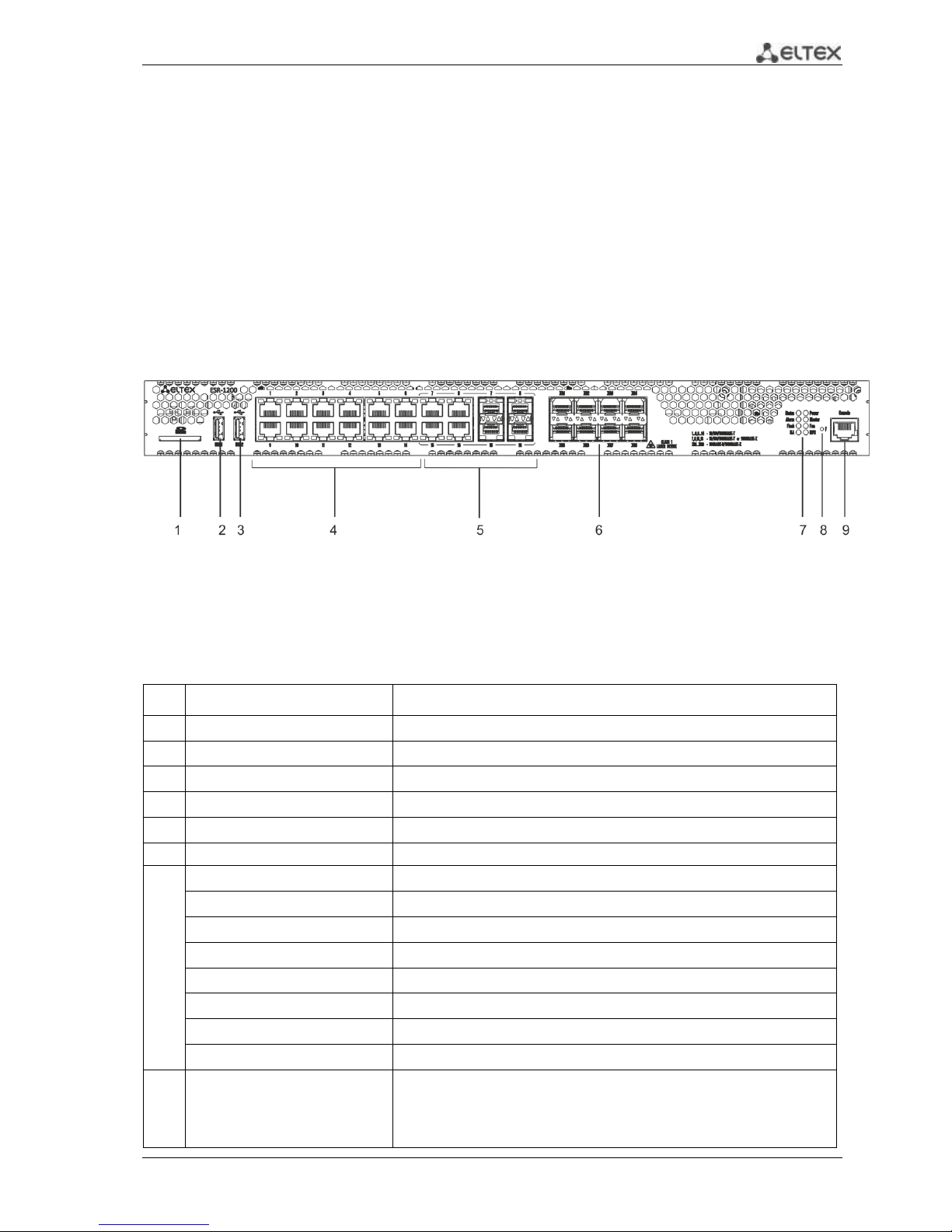
Fig. 2.1 - Front panel of ESR-1200
The list of connectors, light indicators and controls located on the front panel of ESR-1200 lists in
Table 2.9
Table 2.9 - Description of connectors, indicators and controls located on the front panel of ESR-1200
№
Front panel element
Description
1
SD
SD-card connector.
2
USB1
USB-device port.
3
USB2
USB-device port.
4
[1 .. 12]
12 x Gigabit Ethernet 10/100/1000Base-T (RJ-45) ports.
5
Combo Ports
4 x Gigabit Ethernet 10/100/1000Base-X (SFP) ports.
6
XG1 - XG8
10G SFP+/ 1G SFP transceiver installation slots.
7
Status
Indicator of device's current state.
Alarm
indicator of alarm existence and emergency level.
HA
НА operation mode indicator.
Flash
Activity indicator of exchange with data storages (SD-card or USB Flash).
Power
Device power indicator.
Master
Indicator of failover modes operation.
Fan
Fan alarm indicator.
RPS
Backup power source indicator.
8
F
Functional key that reboots the device and resets it to factory settings:
Pressing the key for less than 10 seconds reboots the
device;
Pressing the key for more than 10 seconds resets the
14 ESR Series Routers Operation Manual
terminal to factory settings.
9
Console
Console port RS-232 for local management of the device.
2.4.1.2 ESR-1000 front panel
The front panel layout of the device is depicted in Fig. 2.2.
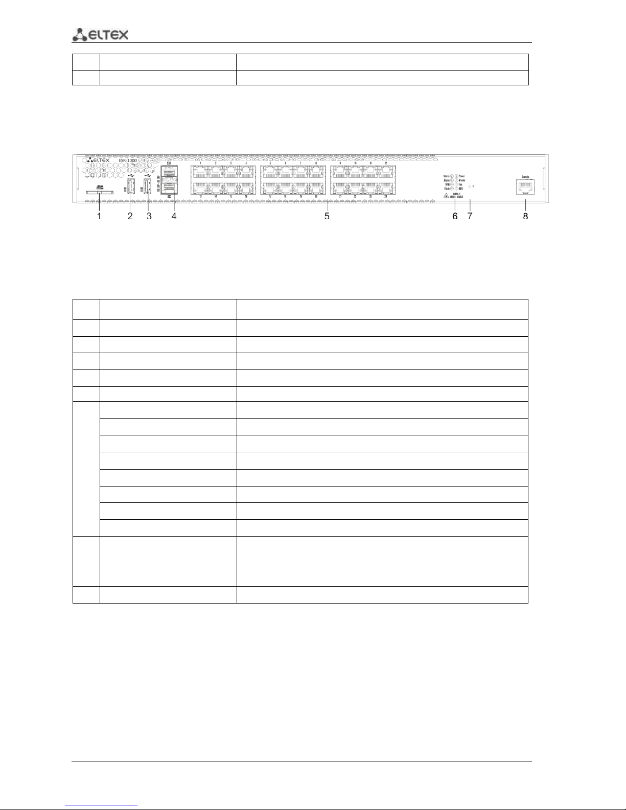
Fig. 2.2 —ESR-1000 front panel
Table 2.10 lists sizes, LEDs, and controls located on the front panel of the device.
Table 2.10 —Description of connectors, LEDs, and controls located on the front panel
No.
Front panel element
Description
1
SD
SD memory card installation slot.
2
USB1
USB-enabled devices connection port.
3
USB2
USB-enabled devices connection port.
4
XG1, XG2
10G SFP+/ 1G SFP transceivers installation slots.
5
[1 .. 24]
24 x Gigabit Ethernet 10/100/1000 Base-T (RJ-45) ports.
6
Status
Current device status indicator.
Alarm
Device alarm presence and level indicator.
VPN
Active VPN sessions indicator.
Flash
Data storage activity indicator—SD card or USB Flash
Power
Device power indicator.
Master
Device failover mode operation indicator.
Fan
Fan alarm indicator.
RPS
Backup power supply indicator.
7
F
Functional key that reboots the device and resets it to factory settings:
– Pressing the key for less than 10 seconds reboots the device.
– Pressing the key for more than 10 seconds resets the device to
factory settings.
8
Console
RS-232 console port for local control of the device.
ESR Series Routers Operation Manual 15
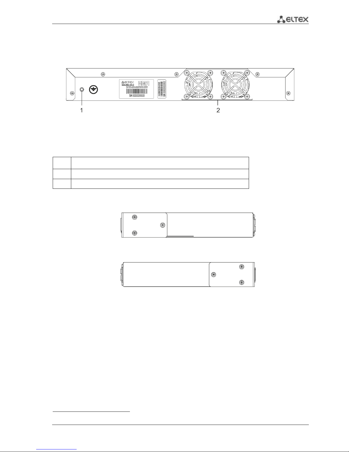
2.4.1.3 ESR-1000, ESR-1200 rear panel
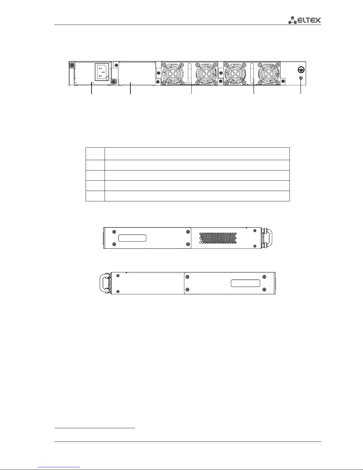
The rear panel layout of ESR-1000, ESR-1200 is depicted in Fig. 2.31.
Fig. 2.3 —ESR-1000, ESR-1200 rear panel
Table 2.11 lists rear panel connectors of the router.
Table 2.11 —Description of rear panel connectors of the router
No.
Description
1
Main power supply.
2
Backup power supply installation position.
3
Removable ventilation modules with hot-swapping.
4
Earth bonding point of the device.
2.4.1.4 Side panels of the device
Fig. 2.4 —The right-side panel of ESR-1000, ESR-1200 routers
Fig. 2.5—The left-side panel of ESR-1000, ESR-1200 routers
Side panels of the device have air vents for heat removal. Do not block air vents. This may cause
components overheating which may result in terminal malfunction. For recommendations on device
installation, see section 'Installation and connection'.
1
The figure shows the router delivery package with a single AC power supply.
1 2 3 3 4
16 ESR Series Routers Operation Manual
2.4.2 ESR-100, ESR-200 design
2.4.2.1 ESR-100, ESR-200 front panel
The front panel layout of ESR-100 is depicted in Fig. 2.6.
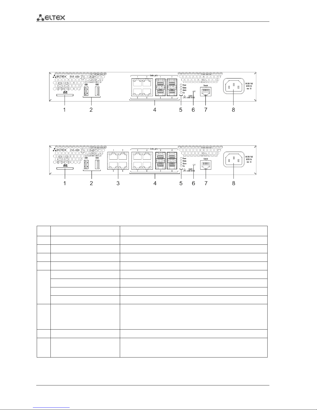
Fig. 2.6 —ESR-100 front panel
The front panel layout of ESR-200 is depicted in Fig. 2.7.
Fig. 2.7 —ESR-200 front panel
Table 2.12 lists sizes, LEDs, and controls located on the front panel of ESR-100 and ESR-200 routers.
Table 2.12 —Description of connectors, LEDs, and controls located on the front panel
No.
Front panel element
Description
1
SD
SD memory card installation slot.
2
USB1, USB2
2 x USB-enabled devices connection port.
3
[1 .. 4]
4 x Gigabit Ethernet 10/100/1000 Base-T (RJ-45) ports.
4
Combo Ports
4 x Gigabit Ethernet 10/100/1000 Base-X (SFP) ports
5
Power
Device power indicator.
Status
Current device status indicator.
Alarm
Device alarm presence and level indicator.
Fan
Fan alarm indicator.
6
F
Functional key that reboots the device and resets it to factory settings:
– Pressing the key for less than 10 seconds reboots the device.
– Pressing the key for more than 10 seconds resets the device to
factory settings.
7
Console
RS-232 console port for local control of the device.
8
110-250VAC
60/50Hz
max 1A
Power supply
ESR Series Routers Operation Manual 17
2.4.2.2 ESR-100, ESR-200 rear panel
The rear panel layout of ESR-100 and ESR-200 routers is depicted in Fig. 2.81.
Fig. 2.8 —ESR-1000, rear panel
Table 2.13 lists rear panel connectors of the router.
Table 2.13 —Description of rear panel connectors of the router
No.
Description
1
Earth bonding point of the device.
2
Ventilation module.
2.4.2.3 ESR-100, ESR-200 side panels
Fig. 2.9 —The right-side panel of ESR-100 and ESR-200 routers
Fig. 2.10—The left-side panel of ESR-100 and ESR200 routers
1
The figure shows the router delivery package with a single AC power supply.
18 ESR Series Routers Operation Manual
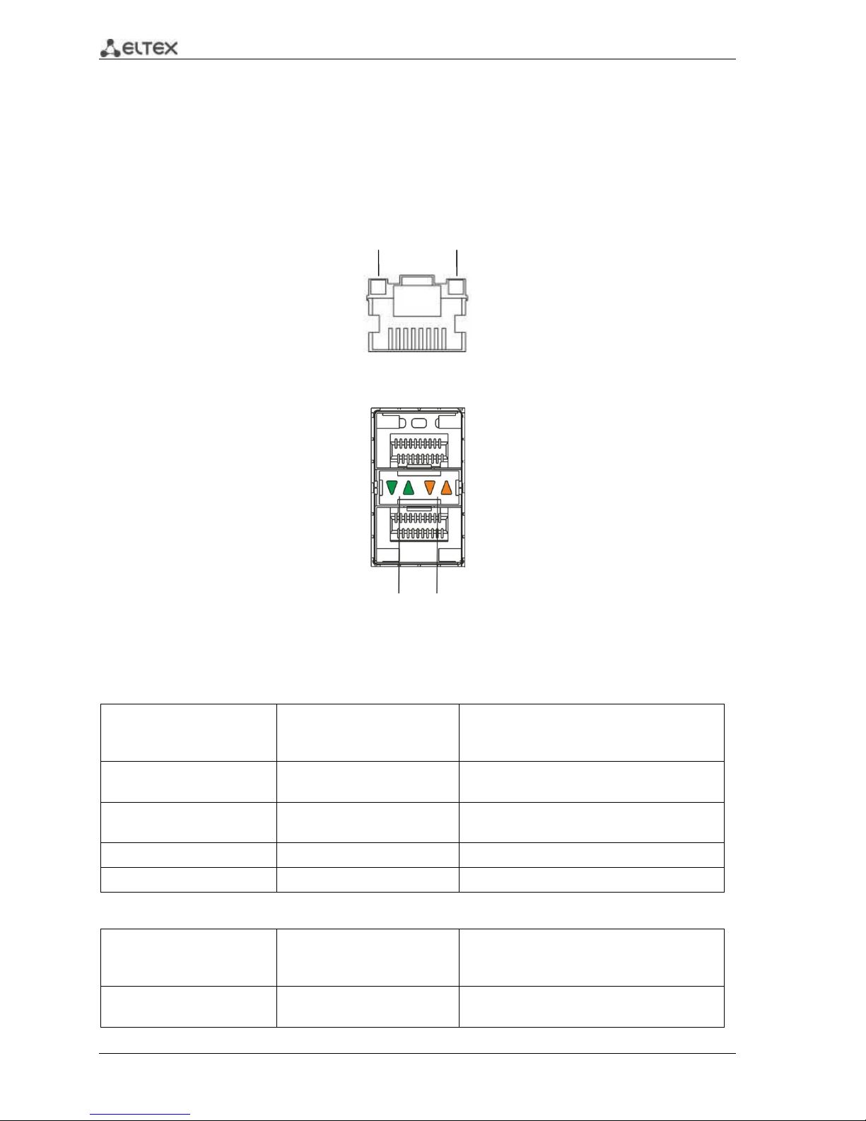
2.4.3 Light Indication
2.4.3.1 ESR-1000, ESR-1200 light indication
Gigabit Ethernet copper interface status is represented by two LEDs—green LINK/ACT LED and
amber SPEED LED. Location of the copper interface LEDs is depicted in Fig. 2.11. SFP interface status is is
represented by two LEDs—RX/ACT and TX/ACT—depicted in Fig. 2.12. For light indication meaning, see
Tables 2.14 and 2.15.
Fig. 2.11 —Location of RJ-45 port indicators
Fig. 2.12 —Location of optical interface indicators
Table 2.14 —Light indication of copper interface status
SPEED indicator is lit
LINK/ACT indicator is lit
Ethernet interface state
Off
Off
Port is disabled or connection is not
established
Off
Solid on
10Mbps or 100Mbps connection is
established
Solid on
Solid on
1000Mbps connection is established
X
Flashes
Data transfer is in progress
Table 2.15 —Light indication of SFP/SFP+ interface status
RX/ACT indicator is lit
TX/ACT indicator is lit
Ethernet interface state
Off
Off
Port is disabled or connection is not
established
LINK/ACT
SPEED
RX/ACT
TX/ACT
ESR Series Routers Operation Manual 19
Solid on
Solid on
Connection established
Flashes
X
Data reception in progress
X
Flashes
Data transfer in progress
The following table lists description of system indicator statuses and meanings.
Table 2.16 —Status of system indicators
Indicator
name
Indicator function
LED State
Device State
Status
Current device status indicator.
Green
Device is in normal operation state.
Orange
Device is booting up the software.
Alarm
Device alarm presence and level
indicator.
-
-
VPN
Active VPN sessions indicator.
-
-
Flash
Data storage activity indicator: SD
card or USB Flash.
Orange
Read/write operation execution with
'copy' command
Power
Device power indicator.
Green
Device power is OK. Main power
supply, if installed, is operational.
Orange
Main power supply failure or fault, or
the primary main is missing.
Off
Device internal power supply failure.
Master
Device failover mode operation
indicator.
-
-
Fan
Cooling fan status.
Off
All fans are operational.
Red
One or more fans has failed. Possible
cause of failure: at least one of the fans
has stopped or is working at lower
rpm.
RPS
Backup power supply operation
mode.
Green
Backup power supply is installed and
operational.
Off
Backup power supply is not installed.
Red
Backup power supply is missing or
failed.
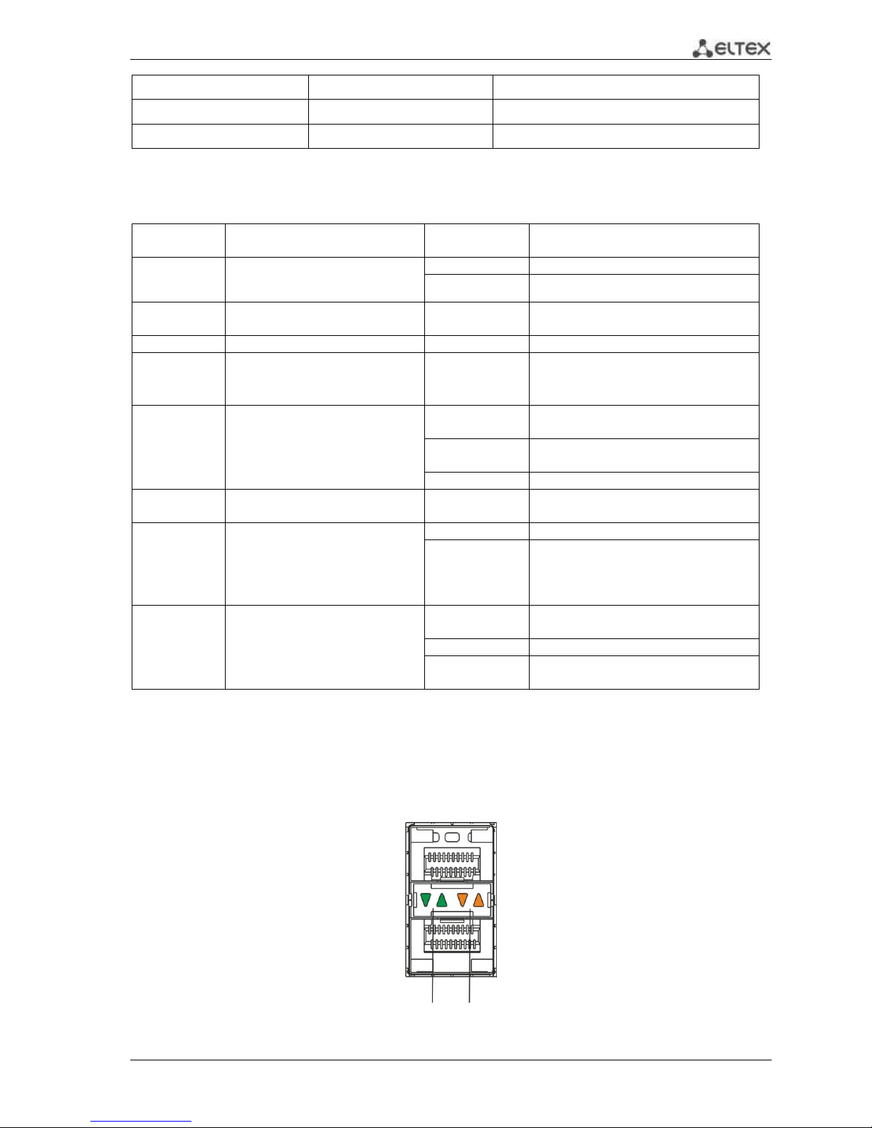
2.4.3.2 ESR-100/ESR-200 light indication
Gigabit Ethernet copper interface and SFP interface statuses are represented by two LEDs—green
LINK/ACT LED and amber SPEED LED. Location of the copper interface LEDs is depicted in Fig. 2.11. SFP
interface status is depicted in Fig. 2.13. For light indication meaning, see Table 2.17.
Fig. 2.13 —Location of optical interface indicators
LINK/ACT
SPEED

20 ESR Series Routers Operation Manual
Table 2.17 —Light indication of copper and SFP interface status
SPEED indicator is lit
LINK/ACT indicator is lit
Ethernet interface state
Off
Off
Port is disabled or connection is not
established
Off
Solid on
10Mbps or 100Mbps connection is
established
Solid on
Solid on
1000Mbps connection is established
X
Flashes
Data transfer in progress
The following table lists description of system indicator statuses and meanings.
Table 2.18 —Status of system indicators
Indicator
name
Indicator function
LED State
Device State
Status
Current device status indicator.
Green
Device is in normal operation state.
Orange
Device is booting up the software.
Alarm
Device alarm presence and level
indicator. 1
-
-
Power
Device power indicator.
Green
Device power is OK. Main power
supply, if installed, is operational.
Orange
Main power supply failure or fault, or
the primary main is missing.
Off
Device internal power supply failure.
Fan
Cooling fan status.
Off
All fans are operational.
Red
One or more fans has failed. Possible
cause of failure: at least one of the fans
has stopped or is working at lower
rpm.
2.5 Delivery Package
ESR-100 standard delivery package includes:
ESR-100 router
Power cable
Console port connection cable (RJ-45 – DB9F)
19” rack mounting kit
Documentation
ESR-200 standard delivery package includes:
ESR-200 router
Power cable
Console port connection cable (RJ-45 – DB9F)
19” rack mounting kit
Documentation
1
Not supported in the current firmware version.

ESR Series Routers Operation Manual 21
ESR-1000 standard delivery package includes:
ESR-1000 router
Power cable
Console port connection cable (RJ-45 – DB9F)
19” rack mounting kit
Documentation
ESR-1200 standard delivery package includes:
– ESR-1200 router;
– power cable;
– Console port connection cable (RJ-45 – DB9F);
– 19” rack mounting kit;
– Documentation.
Power module (PM-160-220/12 or PM-75-48/12) may be included in the ESR-1000 delivery
package on the customer's request.
SFP/SFP+ transceivers may be included in the delivery package on the customer's request.
22 ESR Series Routers Operation Manual
3 INSTALLATION AND CONNECTION
This section describes installation of the device into a rack and connection to a power supply.
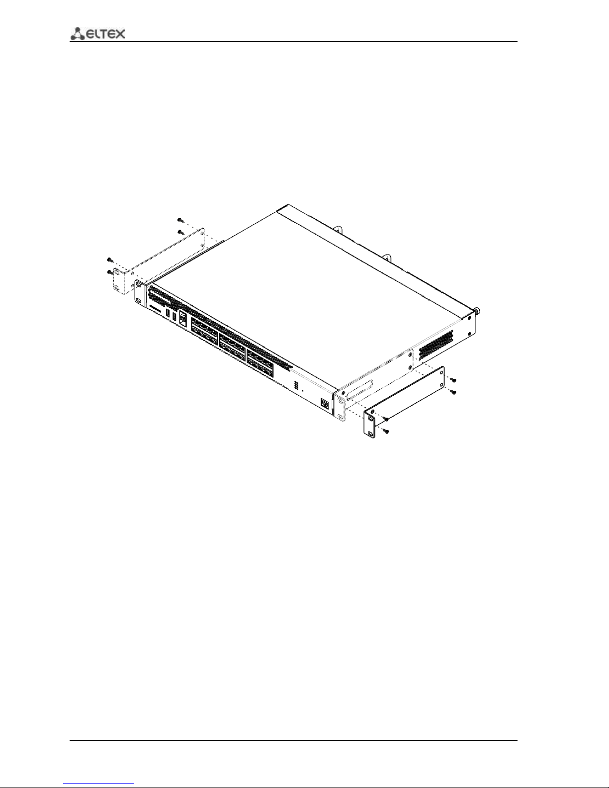
3.1 Support brackets mounting
The delivery package includes support brackets for rack installation and mounting screws to fix the
device case on the brackets. To install the support brackets:
Fig. 3.1 —Support brackets mounting
1. Align four mounting holes in the support bracket with the corresponding holes in the side
panel of the device.
2. Use a screwdriver to screw the support bracket to the case.
3. Repeat steps 1 and 2 for the second support bracket.
ESR Series Routers Operation Manual 23
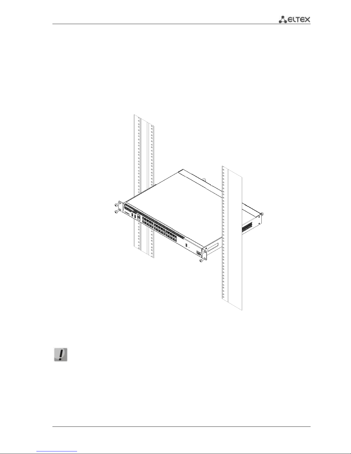
3.2 Device rack installation
To install the device to the rack:
1. Attach the device to the vertical guides of the rack.
2. Align mounting holes in the support bracket with the corresponding holes in the rack
guides. Use the holes of the same level on both sides of the guides to ensure the device
horizontal installation.
3. Use a screwdriver to screw the router to the rack.
Fig. 3.2 —Device rack installation
Device ventilation system is implemented using 'front-rear' layout. Vents are located on
the front and side panels of the device; ventilation modules are located at the rear. Do
not block air inlet and outlet vents to avoid components overheating and subsequent
device malfunction.
24 ESR Series Routers Operation Manual
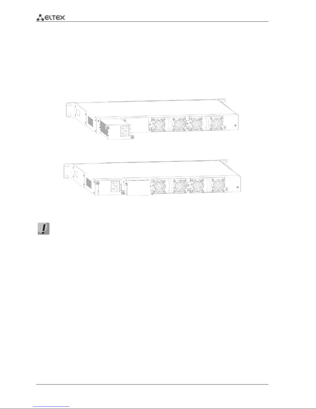
3.3 ESR-1000, ESR-1200 power module installation
ESR-1000 router can operate with one or two power modules. The second power module
installation is necessary when the device operates under strict reliability requirements.
From the electric point of view, both places for power module installation are identical. In the
context of device operation, the power module located closer to the edge is considered as the main
module, and the one closer to the centre—as the backup module. Power modules can be inserted and
removed without powering the device off. When additional power module is inserted or removed, the
router continues operation without reboot.
Fig. 3.3 —Power module installation
Fig. 3.4 —Cover installation
Power module fault indication may be caused not only by the module failure, but also by
the absence of the primary power supply.
You can check the state of power modules by the indication on the front panel of the router (see
Section 2.4.3) or by diagnostics, available through the router management interfaces.
3.4 Connection to Power Supply
1. Ground the case of the device prior to connecting it to the power supply. An insulated
multiconductor wire should be used for earthing. The device grounding and the earthing
wire cross-section should comply with Electric Installation Code.
2. If a PC or another device is supposed to be connected to the router console port, the device
should be also securely grounded.
3. Connect the power supply cable to the device. Depending on the delivery package, the
device can be powered by AC or DC electrical network. To connect the device to AC power
supply, use the cable from the delivery package. To connect the device to DC power supply,
use the cable with cross-section not less than 1mm2.
4. Turn the device on and check the front panel LEDs to make sure the terminal is in normal
operating conditions.
ESR Series Routers Operation Manual 25
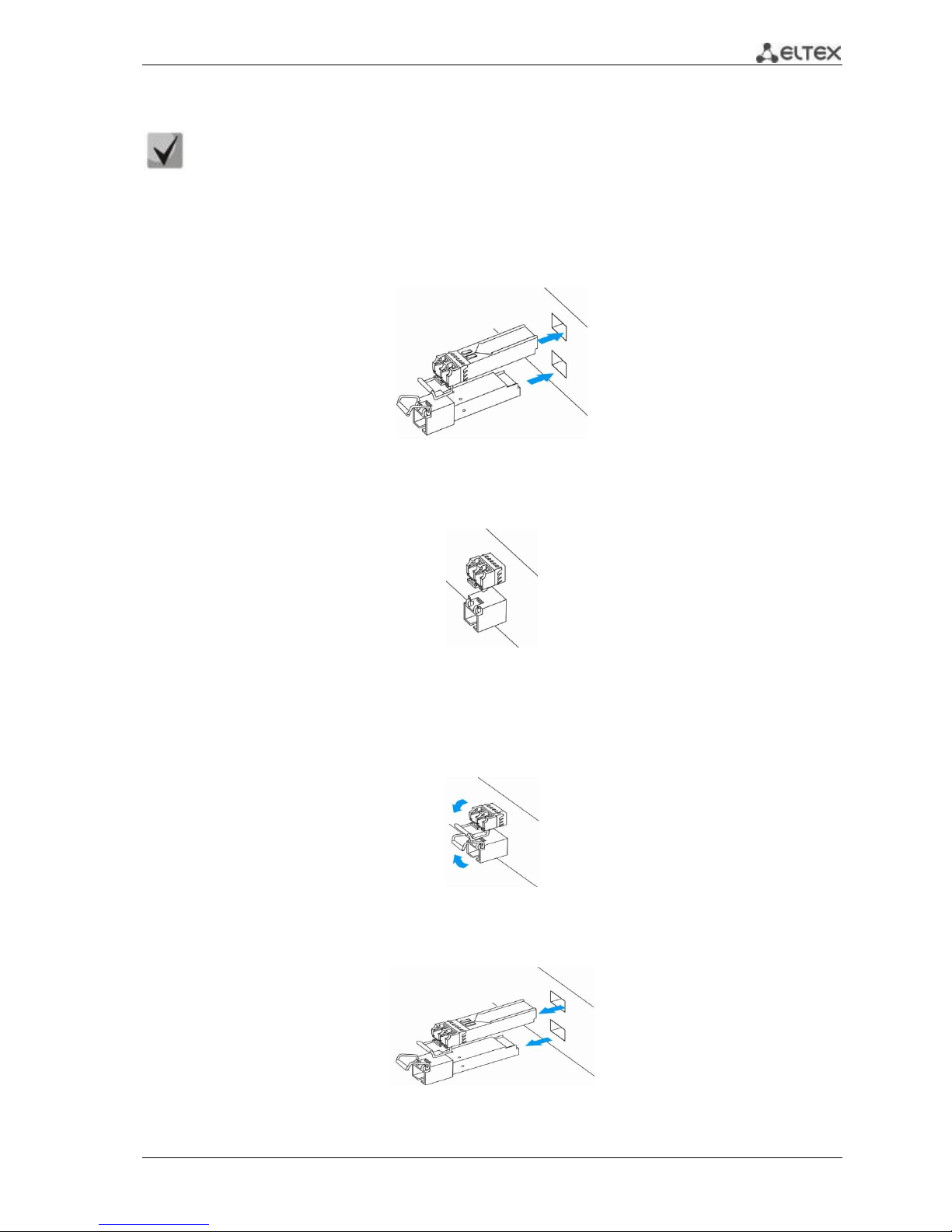
3.5 SFP transceiver installation and removal
Optical modules can be installed when the terminal is turned on or off.
Transceiver installation
1. Insert the top SFP module into a slot with its open side down, and the bottom SFP module with its
open side up.
Fig. 3.5 —SFP transceiver installation
2. Push the module into the device housing until the it is secured with a clicking sound.
Fig. 3.6 —Installed SFP transceivers
Transceiver removal
1. Flip the module handle to unlock the latch.
Fig. 3.7 —Opening the Latch of SFP Transceivers
2. Remove the module from the slot.
Fig. 3.8 —SFP transceiver removal

26 ESR Series Routers Operation Manual
4 MANAGEMENT INTERFACES
You may use various management interfaces in order to control and monitor the device.
To access the device, you may use network connection via Telnet or SSH as well as direct
connection via RS-232 compliant console port. For Telnet, SSH or console port connections, the command
line interface is used for device management.
Factory settings contain trusted zone description and IP address for device management
access—192.168.1.1/24.
Trusted zone includes the following interfaces:
For ESR-100: GigabitEthernet 1/0/2-4;
For ESR-200: GigabitEthernet 1/0/2-8;
For ESR-1000: GigabitEthernet 1/0/2-24;
For ESR-1200: GigabitEthernet 1/0/2-16, TengigabitEthernet 1/0/3-8
By default, the user 'admin' with the password 'password' is defined in factory settings.
For each management interface provided, there are unified configuration operating principles.
When modifying and applying the configuration, you should follow the specific sequence described herein
that is intended to protect the device from misconfiguration.
4.1 Command line interface (CLI)
Command Line Interface (CLI) allows to perform the device management and monitor its operation
and status. You will require the PC application supporting Telnet or SSH protocol operation or direct
connection via the console port (e.g. HyperTerminal).
Command line interface enables user authorization and restricts access to commands depending on
their access level, provided by the administrator.
You can create as many users as you like, access rights will be assigned individually to each user.
To ensure command line interface security, all commands are divided into 2 categories—privileged
and unprivileged. Privileged commands basically include configuration commands. Unprivileged
commands include monitoring commands.
The system allows multiple users to connect to the device simultaneously.

ESR Series Routers Operation Manual 27
5 INITIAL ROUTER CONFIGURATION
5.1 ESR router factory settings
The device is shipped to the consumer with the factory configuration installed which includes
essential basic settings. Factory configuration allows you to use the router as a gateway with SNAT
without applying any additional settings. Also, factory configuration contains settings that allow you to
obtain network access to the device for advanced configuration.
Description of factory settings
To establish network connection, the configuration features 2 security zones named 'Trusted' for
local area network and 'Untrusted' for public network. All interfaces are divided between two security
zones:
1. 'Untrusted' zone is meant for a public network (WAN) connection. In this zone, DHCP ports are
open in order to obtain dynamic IP address from the provider. All incoming connections from this zone to
the router are blocked.
This security zone includes the following interfaces:
For ESR-100 and ESR-200: GigabitEthernet 1/0/1;
For ESR-1000 and ESR-1200: GigabitEthernet1/0/1, TengigabitEthernet1/0/1,
TengigabitEthernet1/0/2.
Zone interfaces are grouped into a single L2 segment via Bridge 2 network bridge.
2. 'Trusted' zone is meant for a local area network (LAN) connection. In this zone, the following
ports are open: Telnet and SSH ports for remote access, ICMP ports for router availability test, DHCP ports
for clients obtaining IP addresses from the router. Outgoing connections from this zone into the Untrusted
zone are allowed.
This security zone includes the following interfaces:
For ESR-100: GigabitEthernet 1/0/2-4;
For ESR-200: GigabitEthernet1/0/2-8;
For ESR-1000: GigabitEthernet1/0/2-24;
For ESR-1200: GigabitEthernet1/0/2-16, TengigabitEthernet1/0/3-8;
Zone interfaces are grouped into a single L2 segment via Bridge 1 network bridge.
On the Bridge 2 interface, DHCP client is enabled to obtain dynamic IP address from the provider.
On Bridge 1 interface, static IP address 192.168.1.1/24 is configured. Created IP address acts as a gateway
for LAN clients. For LAN clients, DHCP address pool 192.168.1.2-192.168.1.254 is configured with the mask
255.255.255.0. For clients in order to access the Internet, the router should have Source NAT service
enabled.

28 ESR Series Routers Operation Manual
Security zone policies have the following configuration:
Table 5.1 —Security zone policy description
Traffic origin zone
Traffic destination
zone
Traffic type
Action
Trusted
Untrusted
TCP, UDP, ICMP
enabled
Trusted
Trusted
TCP, UDP, ICMP
enabled
Trusted
self
TCP/23(Telnet), TCP/22(SSH), ICMP,
UDP/67(DHCP Server), UDP/123(NTP)
enabled
Untrusted
self
UDP/68(DHCP Client),
enabled
To enable device configuration on the first startup, 'admin' account has been created in the
router configuration. We strongly recommend to change administrator password during the
initial configuration of the router.
To enable network access to the router on the first startup, static IP address 192.168.1.1/24
has been configured on Bridge 1 interface.
5.2 Router connection and configuration
ESR series routers are intended to perform border gateway functions and securing the user network
when it is connected to public data networks.
Basic router configuration should include:
Assigning IP addresses (static or dynamic) to the interfaces that participate in data routing
Creation of security zones and distribution of interfaces between these zones
Creation of policies governing data transfer through these zones
Configuration of services that accompany the data routing (NAT, Firewall, etc.)
Advanced settings depend on the requirements of the specific device application pattern and may
be easily added or modified with the existing management interfaces.
5.2.1 Connection to the router
There are several device connection options:
5.2.1.1 Ethernet LAN connection
Upon the initial startup, the router starts with the factory configuration. For factory
configuration description, see Section 5.1 of this Manual.
Connect the network data cable (patch cord) to any port within the 'Trusted' zone and to the PC
intended for management tasks.
In the router factory configuration, DHCP server is enabled with IP address pool in 192.168.1.0/24
subnet.
When network interface is connected to the management computer, the latter should obtain the
network address from the server.

ESR Series Routers Operation Manual 29
If IP address is not obtained for some reason, assign the interface address manually using any
address except for 192.168.1.1 in 192.168.1.0/24 subnet.
5.2.1.2 RS-232 console port connection
Using RJ-45/DBF9 cable included into device delivery package, connect the router 'Console' port to
the computer RS-232 port.
Launch terminal application (e.g. HyperTerminal or Minicom) and create a new connection. VT100
terminal emulation mode should be used.
Specify the following settings for RS-232 interface:
Bit rate: 115200bps
Data bits: 8bit
Parity: no
Stop bits: 1
Flow control: none
5.2.2 Basic router configuration
Upon the first startup, the router configuration procedure includes the following steps:
Changing password for "admin" user.
Creation of new users.
Assigning device name (Hostname).
Setting parameters for public network connection in accordance with the provider
requirements.
Configuring remote connection to router.
Applying basic settings.
5.2.2.1 Changing password for "admin" user
To ensure the secure system access, you should change the password for the privileged 'admin'
user.
'techsupport' account ('eltex' up to version 1.0.7) is required for service center specialist
remote access.
'remote' account — RADIUS, TACACS+, LDAP authentication.
'admin', 'techsupport', 'remote' users cannot be deleted. You may only change passwords
and a privilege level.
Username and password are required for login during the device administration sessions.
To change 'admin' password, use the following commands:
esr# configure
esr(config)# username admin
esr(config-user)# password <new-password>
esr(config-user)# exit

30 ESR Series Routers Operation Manual
5.2.2.2 Creation of new users
Use the following commands to create a new system user or configure the username, password, or
privilege level:
esr(config)# username <name>
esr(config-user)# password <password>
esr(config-user)# privilege <privilege>
esr(config-user)# exit
Privilege levels 1–9 allow you to access the device and view its operation status, but the
device configuration is disabled. Privilege levels 10–14 allow both the access to the device
and configuration of majority of its functions. Privilege level 15 allows both the access to
the device and configuration of all its functions.
Example of commands, that allow you to create user 'fedor' with password '12345678' and privilege
level 15 and create user 'ivan' with password 'password' and privilege level '1:'
esr# configure
esr(config)# username fedor
esr(config-user)# password 12345678
esr(config-user)# privilege 15
esr(config-user)# exit
esr(config)# username ivan
esr(config-user)# password password
esr(config-user)# privilege 1
esr(config-user)# exit
5.2.2.3 Assigning device name
To assign the device name, use the following commands:
esr# configure
esr(config)# hostname <new-name>
When a new configuration is applied, command prompt will change to the value specified by <new-name>
parameter.
5.2.2.4 Configuration of public network parameters
To configure router network interface in the public network, you should assign parameters defined by the
network provider—default IP address, subnet mask and gateway address—to the device.
Example of static IP address configuration commands for GigabitEthernet 1/0/2.150 sub-interface
used for obtaining access to the router via VLAN 150.
Interface parameters:
IP address: 192.168.16.144;
Subnet mask: 255.255.255.0;
Default gateway IP address: 192.168.16.1.
esr# configure
esr(config)# interface gigabitethernet 1/0/2.150
esr(config-subif)# ip address 192.168.16.144/24
esr(config-subif)# exit
esr(config)# ip route 0.0.0.0/0 192.168.16.1
 Loading...