

Elterm goldline asd-w, goldline asdc-w, goldline aszn-w, goldline asbii, redline ashn Operating And Assembly Manual
...
1
Elterm M.M.Kaszuba Sp.J., ul. Przemysłowa 5, 86-200 Chełmno
Operating and assembly manual:
electric tankless water heater for central heating systems
(Electric heating boiler)
GoldLine series:
RedLine series:
AsZN-W (Pułkownik/Uranus/Urano)
AsD-W (Generał/Neptune/Nettune)
AsDC-W (Marszałek/Pluto/Plutone)
AsBII (Bateria/Sun/Sole)
AsHN (Hetman/Moon/Luna)
AsBIV (Dywizja/Galaxy/Galassia)
Please see video prior installation

2
Elterm M.M.Kaszuba Sp.J., ul. Przemysłowa 5, 86-200 Chełmno
DIMENSIONS AND COMPONENTS OF ELECTRIC HEATING BOILERS
(for more detailed pictures please see www.elterm.pl)
Dimensions and components of AsD-W boiler
Dimensions and components of AsZN-W boiler
Dimensions and components of AsBII boiler
Dimensions and components of AsDC-W boiler
Dimensions and components of AsDC-W boiler

3
Elterm M.M.Kaszuba Sp.J., ul. Przemysłowa 5, 86-200 Chełmno
APPLICATION
All GoldLine and RedLine heating boilers are designed to provide heating to small and medium sized
locations equipped with either open or closed low-temperature (T<100°C) central heating water systems.
AsZN-W and AsHN boilers in closed central heating system – those models are designed for autonomous
operation in both open and closed central heating systems – safety unit, expansion vessel and circulation
pump are included.
AsD-W boiler in closed central heating system – this model is designed for autonomous operation in both
open and closed central heating systems – safety unit, expansion vessel and circulation pumps are
included. Additional hot utility water tank with coil (at least 12kW) is needed for proper boiler operation.
AsDC-W boiler in closed central heating system – this model is designed for autonomous operation in both
open and closed central heating systems – safety unit, expansion vessel and circulation pumps are
included. Boiler is build-in on top of 100l hot utility water tank equipped with 29kW coil.
AsBII and AsBIV boilers in closed central heating system - in closed type layout, the central system needs to
be equipped with an expansion vessel, which is not supplied with above models.
1. External metal cast
2. Mounting plate
3. Automatics mounting bracket
4. LED display
5. Control panel
6. Room thermostat connection strip
7. Boiler body
8. Boiler insulation
9. Heating unit
10. Automatic air vent ⅜’’
11. Terminal strip
12. Relays
13. Feed pipe ¾’’ (1’’ in AsBII and AsBIV)
14. Return pipe ¾’’ (1’’ in AsBII and AsBIV)
15. Electronic pump for C.H.
16. Safety valve 3 bar
17. Manometer 4 bar
18. Expansion vessel 8l
19. Return pipe ¾’’ for D.H.W. (in AsD-W only)
20. Electronic pump for D.H.W. (in AsD-W and
.AsDC-W only)
21. Switch ignition
22. Solar air vent
23. Industrial SSR relays
24. Metal manometer 4 bar
Dimensions and components of AsHN boiler
Dimensions and components of AsBIV boiler

4
Elterm M.M.Kaszuba Sp.J., ul. Przemysłowa 5, 86-200 Chełmno
HYDRAULIC ASSEMBLY
All GoldLine and RedLine boilers are hanging (except AsDC-W), vertical devices and
after taking down external metal cast, should be hung on the wall using attached
mounting screws.
Electric heating boiler has to be connected to the central heating system using
couplings (¾”, 1” or 1¼” – depending on model) according to the direction of water
flow (see glued arrows on boiler). Connection to be made in accordance with PN91/B-02413 (open systems), PN-91/B-02414 (closed systems) or applicable
regulations valid in the country of installation. Central heating system has to be
thoroughly flushed prior installation. Non-return valves (see upper picture on the
right) are mandatory for proper AsD-W boiler operation (not supplied with boiler).
For AsDC-W (see bottom picture on the right) one-way valves for C.H. and D.H.W.
are factory assembled. Legend: 1 – C.H. feed, 2 – D.H.W. feed, 3 – circulation, 4 –
cold water inflow, 5 – C.H. return.
ELECTRICAL ASSEMBLY
Connection to the electrical system needs to be done in accordance with regulations applicable in the
country where the given boiler is installed and therefore must be done by a qualified electrician only.
Boilers are designed for alternating current, 3-phase power supply (400V 3N~50Hz). Models with 4, 6, 9, 12
and 15kW powers are also available without any processing in 1-phase version (230V 1N~50Hz), greater
powers can also be prepared in 1-phase version upon request. Boiler’s power supply is connected to
terminal strip labeled as L1L2L3N or to switch ignition (for AsBII, AsHN and AsBIV). PE wire needs to be
connected to screw on mounting plate. Technical data table (below) provides information on the crosssection connecting power cord, the applicable parameters of the main fuse protecting boiler, as well as
estimated heated areas for main and alternative heating source. Boiler should be connected to permanent
electrical system via device enabling boiler’s disconnection from heating source at all ends, with the
distance between contactors not less than 3mm.
BASIC DATA
Connection strip (sensors)
A – CH measurement (CH)
B – connection to hydraulic balancer (BAL)
C – CH measurement (CH) - option
D – D.H.W. measurement (HUW)
E – inside/room temp. measurement (ROOM)
F – outside temp. measurement/weather compensation (WEAT)
G – outside thermostat/room temp. measurement
H – outside thermostat – D.H.W. temperature measurement
Please familiarise yourself with the electrical and hydraulic diagram and technical
data prior to assembly.
5
Elterm M.M.Kaszuba Sp.J., ul. Przemysłowa 5, 86-200 Chełmno
Connecting inside (room) and outside (weather compensation) temperature sensors
Inside temperature sensor is connected to boiler by 2-strand wire using terminal E, outside temperature
sensor using terminal F, wire is not included.
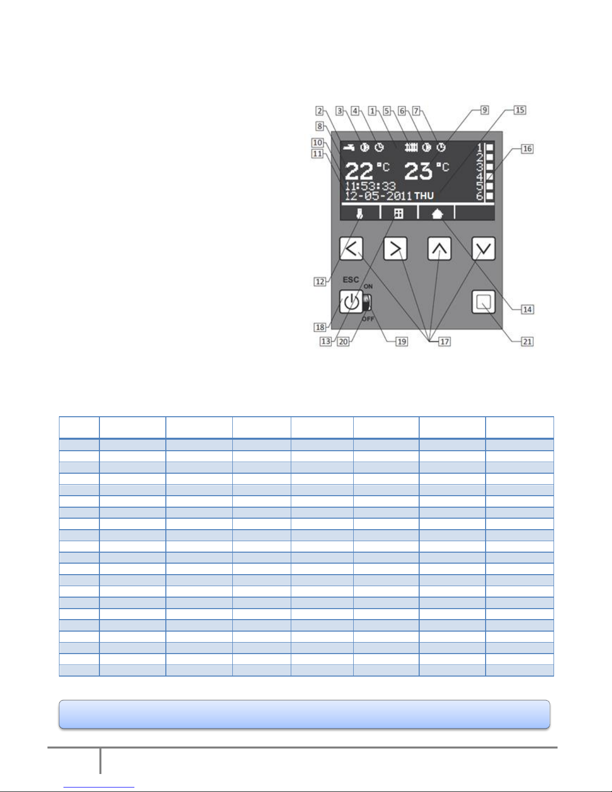
LED display, signaling system and control
Technical data table
Boiler
power
Manual power
distribution (%)
Power
modulation
Power supply
230/400V
Safety
fuses (A)
Power cord
(mm²)
Heated area A
(m²)*
Heated area B
(m²)**
4 kW
100 – 67 – 33
by 1/3
1 phase
1 x 20
3 x 2,5
~ 50
~ 70
4 kW
100 – 67 – 33
by 1/3
3 phases
3 x 6
5 x 1,5
~ 50
~ 70
6 kW
100 – 67 – 33
by 1/3
1 phase
1 x 32
3 x 4,0
~ 70
~ 100
6 kW
100 – 67 – 33
by 1/3
3 phases
3 x 10
5 x 2,5
~ 70
~ 100
9 kW
100 – 67 – 33
by 1/3
1 phase
1 x 40
3 x 10,0
~ 110
~ 150
9 kW
100 – 67 – 33
by 1/3
3 phases
3 x 16
5 x 2,5
~ 110
~ 150
12 kW
100 – 67 – 33
by 1/3
1 phase
1 x 63
3 x 10,0
~ 150
~ 210
12 kW
100 – 67 – 33
by 1/3
3 phases
3 x 20
5 x 4,0
~ 150
~ 210
15 kW
100 – 67 – 33
by 1/6
1 phase
1 x 80
3 x 10,0
~ 180
~ 250
15 kW
100 – 67 – 33
by 1/6
3 phases
3 x 25
5 x 4,0
~ 180
~ 250
18 kW
100 – 67 – 33
by 1/6
3 phases
3 x 32
5 x 6,0
~ 220
~ 310
21 kW
100 – 67 – 33
by 1/6
3 phases
3 x 40
5 x 6,0
~ 260
~ 360
24 kW
100 – 67 – 33
by 1/6
3 phases
3 x 40
5 x 10,0
~ 300
~ 400
27 kW
100 – 67 – 33
by 1/6
3 phases
3 x 50
5 x 16,0
~ 220 - 380
30 kW
100 – 67 – 33
by 1/6
3 phases
3 x 50
5 x 16,0
~ 240 - 400
33 kW
100 – 67 – 33
by 1/6
3 phases
3 x 50
5 x 16,0
~ 260 - 450
36 kW
100 – 67 – 33
by 1/6
3 phases
3 x 63
5 x 16,0
~ 280 - 480
39 kW
100 – 67 – 33
by 1/6
3 phases
3 x 80
5 x 25,0
~ 290 - 500
42 kW
100 – 67 – 33
by 1/6
3 phases
3 x 80
5 x 25,0
~ 300 - 520
45 kW
100 – 67 – 33
by 1/6
3 phases
3 x 80
5 x 25,0
~ 320 - 570
48 kW
100 – 67 – 33
by 1/6
3 phases
3 x 80
5 x 25,0
~ 340 - 600
* A – Heated area A – boiler as main source of heat ** B – Heated area B – boiler as alternative source of heat
Exact cable cross section must be matched by qualified electrician based on local conditions analysis.
1. LCD screen
2. D.H.W. signal icon
3. D.H.W. pump active icon
4. D.H.W. program active icon
5. C.H. signal icon
6. C.H. pump active icon
7. C.H. program active icon
8. Current D.H.W. temperature
9. Current C.H. temperature
10. Time
11. Date
12. C.H. and D.H.W. temperature setting icon
13. Weather compensation icon
14. Room temperature icon
15. Weekday
16. Relays status
17. Function buttons (symbols ←→↑↓)
18. ON/OFF + return button
19. Green diode – boiler turned on
20. Red diode – boiler turned off
21. Choose button

6
Elterm M.M.Kaszuba Sp.J., ul. Przemysłowa 5, 86-200 Chełmno
PROGRAMMING
Basic settings (multiple pressing of causes return to main menu)
Boiler is on, in stand-by mode – red diode is visible (no 20 on display) – recommended mode in summer
season. For 5 seconds press , what should cause green diode to light (no 19). Using ↑↓ please choose
available language (A)(Polish, English, German, French – depending on program version), confirm with ←.
Display now shows „Venting” and progress bar (B), which counts down 5 minutes needed for all essential
activities to vent boiler, pump and whole installation. This function cannot be skipped. In the meantime
C.H. pump is activated (additionally D.H.W. pump for AsDC-W, optionally for AsD-W), and there is no
possibility do turn heaters on. Pre-set venting time should be sufficient to carry out the process, if however
it is not enough – whole procedure needs to be repeated by turning boiler off and on again.
The display switches to the home screen (C).
C.H. and D.H.W. (for AsD-W i AsDC-W) temperature setting – enter function from home screen (C) by
pressing ←, using ↑↓ choose either C.H. or D.H.W. (D). Press to enter temperature setting (E)(F), then
using ↑↓ increase or decrease parameter value. The choice is set by pressing .
Weather compensation curve (G) – enter function from home screen (C) by pressing →, using ↑↓ choose
weather compensation curve from 0 to 10. Curves operate for outside temperatures lower than 15°C, with
Make sure the boiler is connected to electrical system in accordance with hydraulic and electrical
assembly section, all valves on radiators shall stay completely open.

7
Elterm M.M.Kaszuba Sp.J., ul. Przemysłowa 5, 86-200 Chełmno
zero meaning no compensation. In standard operation mode, boiler maintains preset temperature
increased by adjustment parameter in accordance with below table.
For every outside temperature degree below 15°C, adjustment parameters are as follow:
K=1
0,1°C
K=3
0,3°C
K=5
0,5°C
K=7
0,7°C
K=9
0,9°C
K=2
0,2°C
K=4
0,4°C
K=6
0,6°C
K=8
0,8°C
K=10
1,0°C
Example (H): Curve is set on K=5 with boiler preset temperature 30°C. For outside temperature over 15°C,
boiler maintains 30°C. When it cools down to 5°C, adjustment will estimate: 10 x 0,5 = 5°C (degrees below
15°C x value for K=5), so the boiler will maintain 35°C; when it’s -5°C, adjustment will estimate 20 x 0,5 =
10°C, so the boiler will maintain 40°C, etc.
Room temperature setting on boiler (I) - enter function from home screen (C) by pressing ↓, using ↑↓
change preset room temperature in range 5-30°C.
Detailed settings (multiple pressing of causes return to main menu)
Menu structure (J, K, L):
1. Settings
1.1. Power
1.2. Sections
1.3. Date & time
1.4. PID-P
1.5. Hysteresis CO
1.6. Hysteresis CWU
1.7. Default settings
1.8. Room programs
1.9. DHW programs
1.10. Circulation pump
1.11. Circulation time
2. Energy consumption
3. Venting
1.1. Settings/Power – press on home screen (C) and enter SETTINGS (J), then choose Power (K) and
press once more. Using ↑↓ change boiler power in range 33/66/100% (M). The choice is set by pressing
.
1.2. Settings/Sections – press on home screen (C) and enter SETTINGS (J), then choose Sections (K) and
press once more. Using ↑↓ switch between C.H. and D.H.W. (N). Press to enter chosen section and
using ↑↓ switch between active (ON)(O) and inactive (OFF)(P) status. The choice is set by pressing .

8
Elterm M.M.Kaszuba Sp.J., ul. Przemysłowa 5, 86-200 Chełmno
1.3. Settings/Date & time – press on home screen (C) and enter SETTINGS (J), then choose Date & time
(K) and press once more. Using ←→ (R) switch between hour, date, weekday, and then using ↑↓
change parameters values, which are set by pressing .
1.4. Settings/PID-P – press on home screen (C) and enter SETTINGS (J), then choose PID-P (K) and press
once more. Using ↑↓ (S) change parameter value, which is then set by pressing . Attention: In case
boiler needs long time to reach set temperature – correct parameter value is 4 or 5, for too quick operation choose 1 or 2.
1.5. Settings/CH Hysteresis – press on home screen (C) and enter SETTINGS (J), then choose CH
Hysteresis (K) and press once more. Using ↑↓ (T) change parameter value (range 1-2-3-4-5-6), which is
then set by pressing .
1.6. Settings/DHW Hysteresis – press on home screen (C) and enter SETTINGS (J), then choose DHW
Hysteresis (L) and press once more. Using ↑↓ (U) change parameter value (range 1-2-3-4-5-6), which is
then set by pressing .
1.7. Settings/Default settings – press on home screen (C) and enter SETTINGS (J), then choose Def.
settings (L) and press once more. Using ← (W/Y) resign from default settings (NO), → agree on those
settings (YES), ↑ activate settings. - confirm choice.
Default settings
DHW temperature.......................................... 50°C
CH temperature................................................ 50°C
Power....................................................................... 100%
DHW sections..................................................... ON
CH sections............................................................ ON
PID-P........................................................................... 3
CH hysteresis........................................................ 6
DHW hysteresis.............................................. 7
9
Elterm M.M.Kaszuba Sp.J., ul. Przemysłowa 5, 86-200 Chełmno
Room and DHW programs - settings
Room and DHW programs enable setting and maintaining requested temperature at any defined time
periods with one minute accuracy. Intuitive menu and illuminated display make the programming process
easy. All settings are stored in non-volatile memory and are not deleted even in case of a power off.
Electronic processor enables setting 9 independent programs, each can define requested temperature
within any given time span.
When two different temperatures from different programs overlap, higher one is prioritized.
I
MO
TU
WE
TH
FR
SA
SU
Active days: all
II
MO WE FR SU
Active days: 4
III
Mo
TH
SU
Active days: 3
IV
MO
TU
WE
TH
FR
SA
SU
Active day: 1 (to choose)
V
MO
TU
WE
TH
FR
Active days: working days
VI SA
SU
Active days: weekend
VII
MO
TU
WE
TH
FR
SA Active days: 6
VIII Active days: any
IX Active days: any
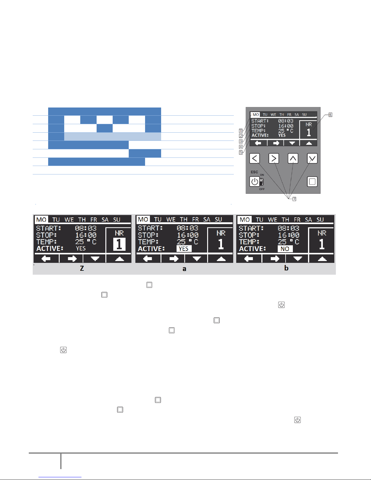
1. Weekdays, 2. Program start, 3. Program stop, 4. Temp. setting: 20-70°C,
5. Active: yes/no, 6. Program number: from 1 to 9, 7. Function buttons
1.8. Settings/ROOM programs – press on home screen (C) and enter SETTINGS (J), then choose Room
programs (L) and press once more. Using ←→ (Z) switch between parameters (weekdays, working time,
temperature, status), using ↑↓ change parameter value, which is then set by pressing .
1.9. Settings/DHW programs (for AsD-W and AsDC-W) – press on home screen (C) and enter SETTINGS
(J), then choose DHW programs (L) and press once more. Using ←→ (Z) switch between parameters
(weekdays, working time, temperature, status), using ↑↓ change parameter value, which is then set by
pressing .
Active/Inactive status – each program can be temporarily turned off. In order to do that, change status
within selected program (either Room or DHW one) for: no (b). To activate previously turned off program –
set status for: yes (a).
1.10. Settings/Circulation pump – press on home screen (C) and enter SETTINGS (J), then choose
Circulation pump and press once more. Using ←→ switch between parameters (weekdays, working
time, temperature, status), using ↑↓ change parameter value, which is then set by pressing .
10
Elterm M.M.Kaszuba Sp.J., ul. Przemysłowa 5, 86-200 Chełmno
1.11. Settings/Circulation time – press on home screen (C) and enter SETTINGS (J), then choose
Circulation time and press once more. Using ↑↓ change parameter value, which is then set by pressing
.
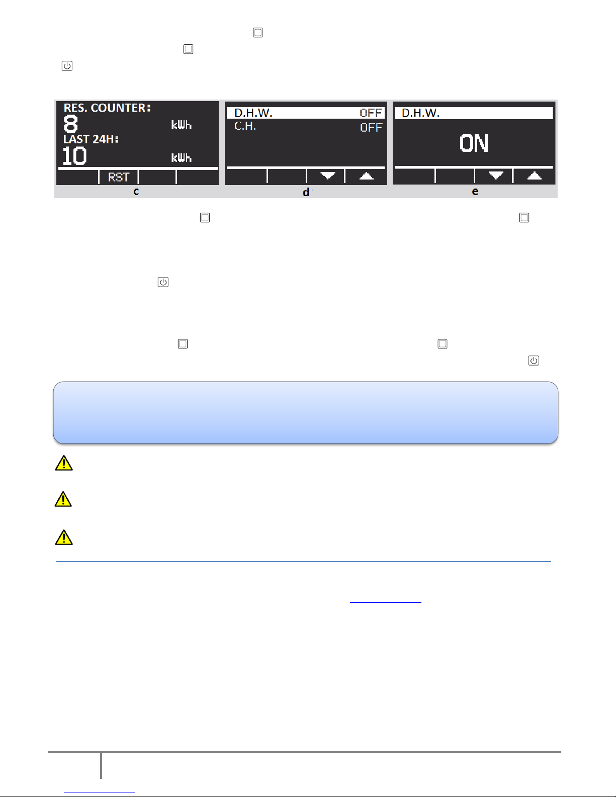
2. Energy consumption - press on home screen (C) and enter ENERGY CONSUMPTION (J). Press once
more to display energy consumption counters (c). Using → reset erasable counter (RES. COUNTER) – which
shows consumed energy in kWh since measurement start till any given moment within 24h time span. After
24 hours, counter stops automatically. LAST 24H – calculates energy consumption over the last 24 hours
with 20 min. updates. - return.
3. Venting – function enables additional system venting without turning boiler off. Proper system venting
guarantees its correct and prolonged, faultless operation. Function also enables to check proper
pump/pumps work. Press on home screen (C) and enter VENTING (J). Press once more to display
D.H.W./C.H. options (d). Using ↑↓ change parameter value- ON/OFF (e), which is then set by pressing .
Do not remove boiler external metal casing once device remains turned on.
In case boiler is activated by mistake with no water inside, wait until heaters cool down, fill device with
water and switch it on again. Under no circumstances fill device with cold water with heaters still hot!
Once water in central heating system is heated, system should be bled once again (special attention
must be paid to the bleeding of the central heating pump and boiler air vent).
For more information please visit www.elterm.pl
Elterm boilers are equipped in AntiStop function. Automatics turns the pump on for one minute once
every 14 days, what prevents it's rotor from seizing. AntiStop operates independently from on/off mode. It
is therefore highly recommended to keep boiler in off mode (red diode visible) in off-heating season - in
this mode device uses just 0,5W!
11
Elterm M.M.Kaszuba Sp.J., ul. Przemysłowa 5, 86-200 Chełmno
Declaration of conformity CE - EN3/2016
Elterm M.M.Kaszuba Sp.j., ul Przemysłowa 5, 86-200, Chełmno, Polska
We herewith declare, under our sole responsibility, that the following products: Tankless water heater for central heating
systems (electric central heating boiler) type EKW As:
Variants:
~ 230V,50Hz, max.power 4kW, 6kW, 9kW,12kW, 15kW, 18kW, 21kW and 24kW
3N~400V,50Hz, max.power 4kW, 6kW, 9kW,12kW, 15kW, 18kW, 21kW, 24kW, 27kW, 30kW, 33kW, 36kW, 39kW,
42kW, 45kW, 48kW and boiler cascades 1,5MW (each boiler up to 48kW)
Models: AsPC, AsP, AsBN, AsZN, AsD, AsBI, AsZN-W, AsD-W, AsDC-W, AsBII, AsHZ, AsHN, AsBIII, AsBIV, AsMB, manufactured at
the Elterm production plant, are in conformity with the applicable provisions of the following EC Directives:
Number
Title
2006/95/WE as amended
Low Voltage Directive (LVD)
2004/108/WE as amended
Electromagnetic Compatibility Directive (EMC)
2002/95/WE as amended
Directive on the restriction of the use of certain hazardous substances in
electrical and electronic equipment (RoHS)
2002/96/WE as amended
Directive on waste electrical and electronic equipment (WEEE), GIOŚ
register number E0001767
ErP 2009/125/WE
General rules for setting requirements concerning Ecodesign for energy
related products (Attachment 13)
EU Commission regulation nr 622/2012
With regard to Ecodesign requirements for glandless standalone
circulators and glandless circulators integrated in products
and that the standards hereinafter referred to have been duly applied and observed. The harmonized standards applicable to
the product to which this declaration of conformity pertains:
Number
Issue
Title
PN-EN 60335-1
2006 (U) as amended
Safety of household and similar devices
PN-EN 60335-2-35
2007 (U) as amended
Particular requirements for tankless water heaters
PN-EN 55014-1
2002 as amended
Interference emission for domestic appliances
PN-EN 55014-2
2004 as amended
Interference immunity
PN-EN 61000-3-2
2004 as amended
Harmonic current emissions
PN-EN 61000-3-11
2000 as amended
Limitation of voltage fluctuations and flicker in low-voltage
supply systems
PN-EN 50366
2006 (U) as amended
Electromagnetic fields- methods for evaluation and
measurement
Other documents or information required by the EC Directives:
Report number:
Laboratory:
B-47/03
KEWA – ECO, Bydgoszcz
CLBT/ZR/67/2003
GP – CLBT, Warszawa
456/BS/EMC/04
PREDOM – OBR, Warszawa
BE/39/2006
Laboratorium Elektrotechniczne PCBC S.A.
BEM-66/07
Laboratorium Badawcze Maszyn i Urządzeń J.N.B. EUROVITA Sp. z o.o.
B-71/07
Laboratorium Badawcze Maszyn i Urządzeń J.N.B. EUROVITA Sp. z o.o.
Chełmno, July 19th 2016

12
Elterm M.M.Kaszuba Sp.J., ul. Przemysłowa 5, 86-200 Chełmno
Boiler’s type, serial number, production date
Date of sales
Legible stamp of a retail outlet and signature
Unless the above stamps are present the guarantee is invalid
GUARANTEE
1. Guarantee for trouble-free operation is valid for a period of 24 months (12 months for AsMB).
2. Guarantee expires if any alterations are made to the product without the manufacturer’s consent, or if assembly or use are
not in accordance with the enclosed operation manual and terms and conditions of guarantee.
3. Guarantee repairs are made by the manufacturer or persons/companies authorized by the same.
4. If filled out incompletely, the guarantee is invalid.
5. If the serviceperson discovers machine failure resulting from the user’s fault (e.g. improperly made wiring system, air-locked
central heating system, use or assembly that is not in compliance with the user manual etc.), or in the event the guarantee is
invalid, the costs of repair and travelling are borne by the claimant.
6. Failure on the part of the user to follow the serviceperson’s recommendations provided in the guarantee repair protocol
results in the guarantee being suspended until such recommendations are implemented.
Do not call servicemen without becoming fully familiarized with the boiler user manual, as well as conditions of guarantee
and assembly. Before you call service, read the section „TROUBLESHOOTING.
Stamp of serviceman, short description of repair and recommendations for the user
Following guarantee repair by the serviceman, one of the below guarantee coupons to be cut off, filled out and handed to the serviceman
Guarantee coupon I
…………………………….……………………………………………………………………………………………………………………………
Full name and address of the boiler owner
…………………………….……………………………………………………………………………………………………………………………
Postal code, town /Boiler owner tel. no.
…………………………….………………………………………… …………………………………………………………
Production date Boiler serial no.
Guarantee coupon II
…………………………….……………………………………………………………………………………………………………
Full name and address of the boiler owner
…………………………….……………………………………………………………………………………………………………………………
Postal code, town /Boiler owner tel. no.
…………………………….………………………………………… …………………………………………………………
Production date Boiler serial no
 Loading...