

Eltek Valere UNV-F 2.5, UNV-F 5.0, UNV-F 3.3 User Manual

DC/AC INVERTER
UNV-F 2.5/3.3/5.0
USER MANUAL
UM_UNVF_E_R2.0

DC/AC Inverter
UNV-F
User Manual
Page 2 (28)
©2009. ELTEK VALERE DEUTSCHLAND GmbH. UM_UNVF_ E_R2.0
Notes to this manual
ATTENTION! Read this manual very carefully before installing
and commissioning the specified module.
This manual is a part of the delivered module. Familiarity with the contents of this manual is required for
installing and operating the specified module.
The rules for prevention of accidents for the specific country and the general safety rules in accordance with
IEC 364 must be observed.
The function description in this manual corresponds to the date of publishing.
Technical changes and changes in form and content can be made at any time by the manufacturer without
notice. There are no obligations to update the manual continually.
The module is manufactured in accordance with applicable DIN and VDE standards such as VDE 0106 (part 100)
and VDE 0100 (part 410). The CE marking on the module confirms compliance with EU standards 2006-95-EG
(low voltage) and 2004-108-EG (electromagnetic compatibility) if the installation and operation instructions are
followed.
Supplier:
ELTEK VALERE DEUTSCHLAND GmbH
GB Industrial
Schillerstraße 16
D-32052 Herford
+ 49 (0) 5221 1708-210
FAX + 49 (0) 5221 1708-222
Email Info.industrial@eltekvalere.com
Internet http://www.eltekvalere.com
2009. ELTEK VALERE DEUTSCHLAND GmbH. All rights reserved.
DC/AC Inverter
UNV-F
User Manual
Page 3 (28)
©2009. ELTEK VALERE DEUTSCHLAND GmbH. UM_UNVF_ E_R2.0
The current revision status of this user manual is the following:
Revision: 2.0
Date: 2009-07-31
Revision Description of change Writer Date
01-03 Minor text modifications RTH
04 ELTEK VALERE INDUSTRIAL layout inserted RTH 2008-01-29
1.0
New revision status numbering (X.X) introduced, section “Error
indication on the displays” inserted.
RTH 2009-04-20
2.0 Minor reworking at sections 3.4, 4.2, 7. RTH 2009-07-31

DC/AC Inverter
UNV-F
User Manual
Page 4 (28)
©2009. ELTEK VALERE DEUTSCHLAND GmbH. UM_UNVF_ E_R2.0
Table of Contents
1A. SAFETY INSTRUCTIONS ........................................................................................................................................5
1B. ELECTRIC WASTE DISPOSAL ................................................................................................................................5
2. GENERAL INFORMATION..........................................................................................................................................6
2.1 TYPICAL APPLICATIONS ...........................................................................................................................................6
3. TYPE RANGE/EQUIPMENT ......................................................................................................................................7
3.1 MOUNTING ACCESSORIES.........................................................................................................................................7
3.2 FRONT VIEW/OPERATION ELEMENTS.......................................................................................................................8
3.3 ELECTRICAL CONNECTORS.......................................................................................................................................9
3.3.1 Electrical Connector X1 for UNV-F 2.5 – 3.3kVA, UNV60-5.0F and UNV110-5.0F ...................9
3.3.2 Electrical Connector X1 for UNV48-5.0F (HAN K 6/6).................................................................. 10
3.3.3 CAN-Bus connectors CAN1 & CAN2.................................................................................................. 11
3.4 COOLING/AIR FLOW DIRECTION ............................................................................................................................ 11
3.5 COMMUNICATION INTERFACE ................................................................................................................................12
4. HANDLING................................................................................................................................................................ 12
4.1 STORAGE.............................................................................................................................................................. 12
4.2 COMMISSIONING ................................................................................................................................................... 12
4.2.1 Single inverter ........................................................................................................................................ 13
4.2.2 Operation in parallel.............................................................................................................................. 13
4.2.3 CAN-Bus Addressing............................................................................................................................. 13
4.3 LED INDICATIONS .................................................................................................................................................14
4.4 INTERNAL MONITORING......................................................................................................................................... 15
4.5 ADJUSTMENT OF THE STANDARD AND THRESHOLD VALUES................................................................................... 16
4.5.1 Diagram “Standard display during operation/display of input and output parameters”..... 17
4.5.2 Diagram “Adjustment mode”...............................................................................................................19
4.5.3 Table “Adjustable Parameters”.......................................................................................................... 21
5. MAINTENANCE........................................................................................................................................................ 22
6. TROUBLE SHOOTING ............................................................................................................................................. 22
6.1 FAILURE TABLE..................................................................................................................................................... 22
6.2 ERROR INDICATION ON THE DISPLAYS .................................................................................................................... 23
7. TECHNICAL SPECIFICATIONS............................................................................................................................... 25
7.1 DIMENSIONAL DRAWINGS ......................................................................................................................................27
DC/AC Inverter
UNV-F
User Manual
Page 5 (28)
©2009. ELTEK VALERE DEUTSCHLAND GmbH. UM_UNVF_ E_R2.0
1A. Safety Instructions
Warning!
Because several components of operating electrical modules are charged by dangerous voltage, the
improper handling of electrical modules may be the cause of accidents involving electrocution,
injury, or material damages.
Operation and maintenance of electrical modules must be performed by qualified skilled
personnel such as electricians in accordance with EN 50110-1 or IEC 60950.
Install the module only in areas with limited access to unskilled personnel.
Before starting work, the electrical module must be disconnected from mains. Make sure
that the module is earthed.
Do not touch connector pins as they can be charged with dangerous voltage up to 30
seconds after disconnection.
Only spare parts approved by the manufacturer must be used.
1B. Electric Waste Disposal
Separate collection is the precondition to ensure specific treatment and recycling of waste electrical and
electronic equipment and is necessary to achieve the chosen level of protection of human health and the
environment.
In the case of waste disposal of your discarded equipment we recommend to contact a waste management
company.

DC/AC Inverter
UNV-F
User Manual
Page 6 (28)
©2009. ELTEK VALERE DEUTSCHLAND GmbH. UM_UNVF_ E_R2.0
2. General Information
Inverters of the series UNV-F convert input side DC voltage to a stable sinusoidal output voltage.
The inverters are available for delivery with an output power of 2.5, 3.3 and 5.0 kVA per module.
Several units can be switched in parallel operation to increase the system output power.
The UNV-F is a hot-pluggable module with rear side connectors. Only the communication wire (CAN-Bus) is
connected at the front. The inverters are controlled and monitored by an internal microprocessor. Due to the
outstanding switching principle the units have very low losses and therefore very compact dimensions, low
weight and a very high power density.
All main functional parameters are adjustable with front side operating keys and are indicated with digital
displays.
To increase the reliability the UNV-F inverter is designed to operate together with a static transfer switch of
series UNB. The static transfer switch monitors the connected bypass mains and synchronizes the inverter
output with mains frequency. In inverter priority mode the UNB transfers the load supply to bypass mains in
case of inverter faults, high overload or battery low voltage. The transfer is nearly without voltage interruption
(<4ms). The unit switches back to inverter operation automatically if the reason for the transfer is gone. In case
of mains priority mode the inverter will take over the load if the mains voltage is not present, out of limits or
heavy disturbed. The priority source is programmable at the UNB unit (see separate manual).
2.1 Typical Applications
(a) Inverter in parallel operation without UNB b) Inverter in parallel operation with UNB
DC/AC Inverter
UNV-F
User Manual
Page 7 (28)
©2009. ELTEK VALERE DEUTSCHLAND GmbH. UM_UNVF_ E_R2.0
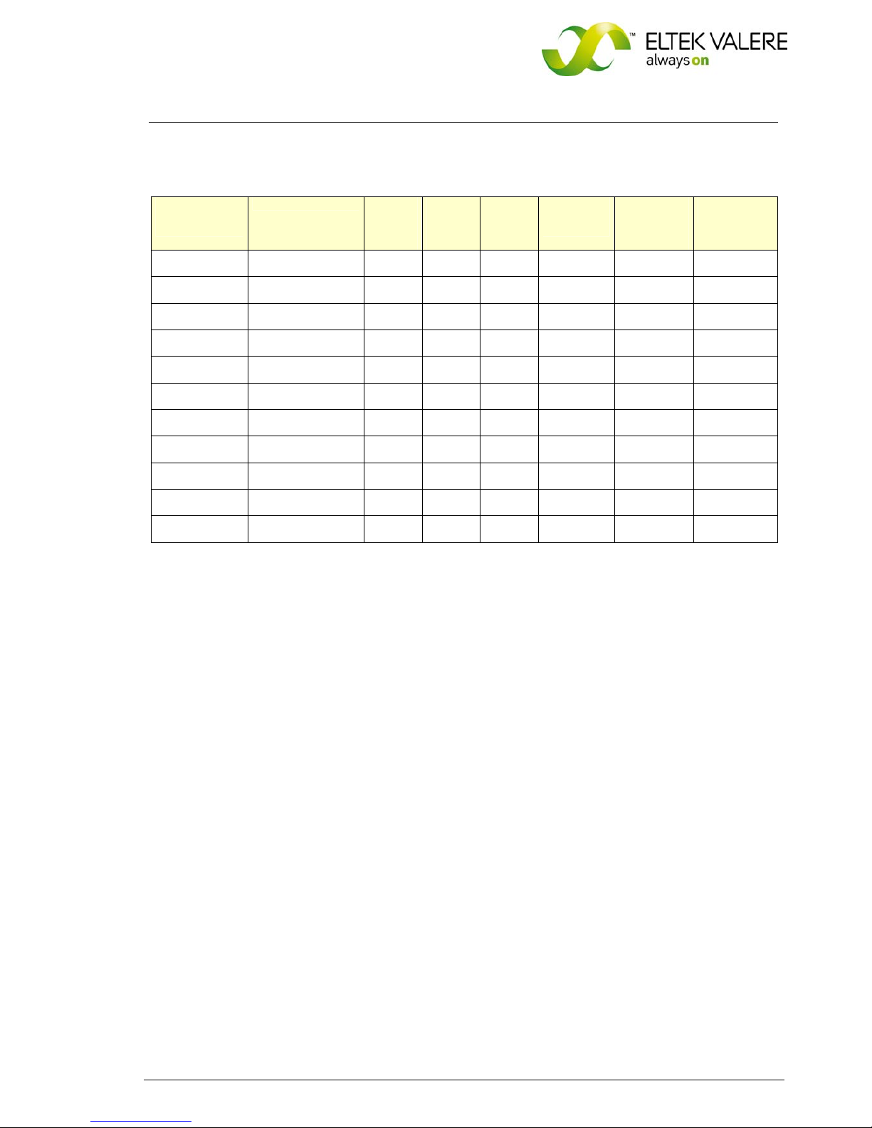
3. Type Range/Equipment
Type
designation
Material code Nominal
Inputvoltage
(VDC)
Nominal
Input
current
(ADC)
Nominal
Outputvoltage
(VAC)
Output
frequency
(Hz)
Outputpower
(VA
@ cosφ =0.8)
Dimensions
W/H/D (mm)
UNV48-2.5F 500-025-511.00 48 47.3 230 50/60 2500 483/133/360
UNV60-2.5F 500-025-611.00 60 37.9 230 50/60 2500 483/133/360
UNV110-2.5F 500-025-711.00 108 20.4 230 50/60 2500 483/133/360
UNV48-3.3F 500-033-511.00 48 62.5 230 50/60 3300 483/133/360
UNV60-3.3F 500-033-611.00 60 50.0 230 50/60 3300 483/133/360
UNV110-3.3F 500-033-711.00 108 26.7 230 50/60 3300 483/133/360
UNV48-5.0F 500-050-511.00 48 94.7 230 50/60 5000 483/133/440
UNV60-5.0F 500-050-611.00 60 74.9 230 50/60 5000 483/133/440
UNV110-5.0F 500-050-711.00 108 39.9 230 50/60 5000 483/133/440
For more specific data, see section 7.
3.1 Mounting accessories
Mounting set for 19’’ cabinet (not for UNV48-5.0F): Mat. code 880-MEC-MKT.01
Mounting set for 19’’ cabinet (for UNV48-5.0F): Mat. code 880-MEC-MKT.02
The mounting set is necessary to fit the UNV module in a 19’’ compatible cabinet (see section 4.2
“commissioning”).
DC/AC Inverter
UNV-F
User Manual
Page 8 (28)
©2009. ELTEK VALERE DEUTSCHLAND GmbH. UM_UNVF_ E_R2.0
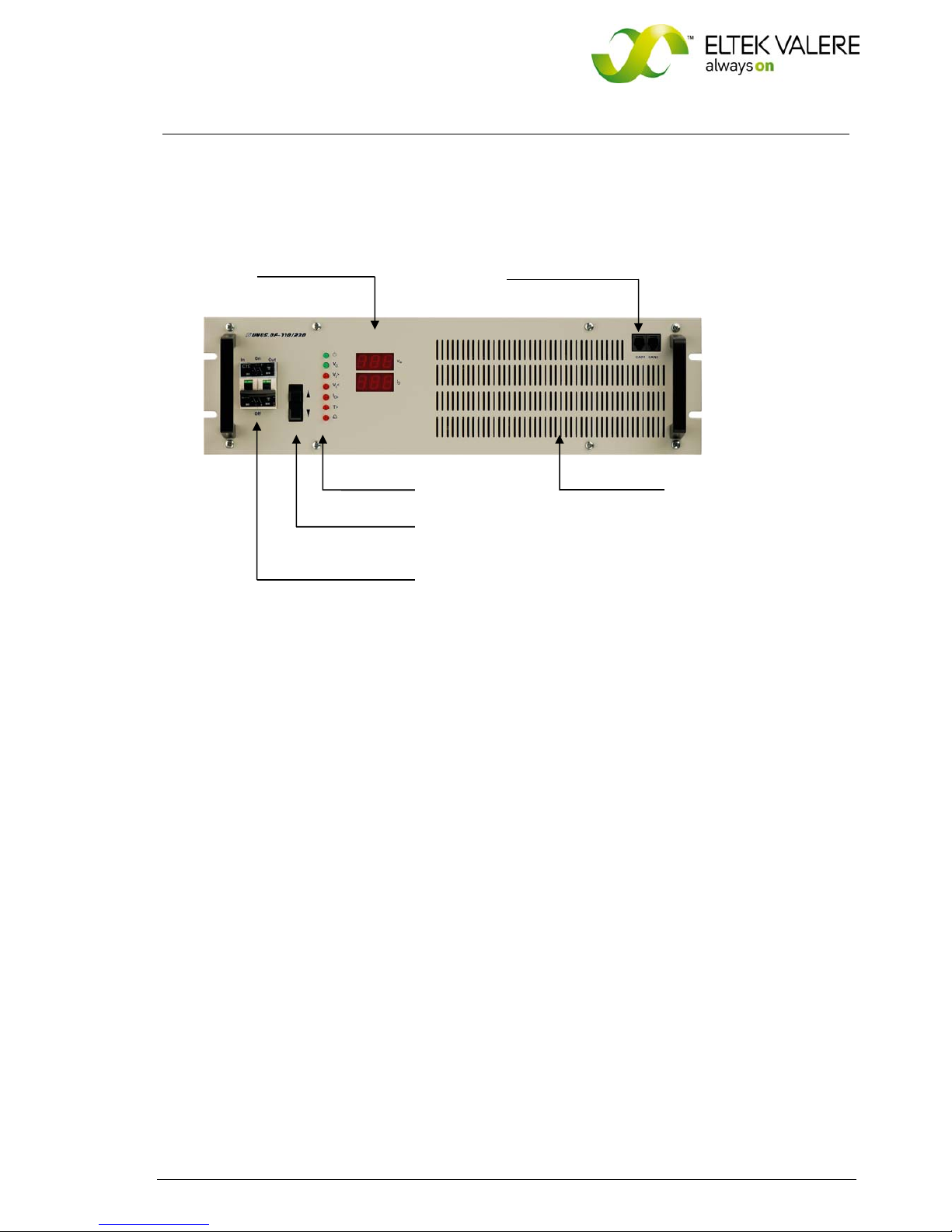
3.2 Front View/Operation Elements
Digital displays Two CAN-Bus connectors
LED indicators Ventilation grid
UP/DOWN keys
ON/OFF switch
(Input/output fuse)
All operating elements are arranged at the front side of the module. The UNV-F, 2.5 and 3.3kVA are fitted with a
combined input and output MCB which is used as ON/OFF switch, whereas the 5.0kVA version is fitted with a
mechanical switch.
As shown with the front view the unit is equipped with seven LED indications:
Switch symbol (Operation)
Vo (Output voltage ok)
Vi> (Input overvoltage)
Vi< (Input undervoltage)
Io> (Overload)
T> (Overtemperature)
Bell symbol (General alarm)
Two digital displays indicate the output voltage and output current values.
Detailed information concerning signalling and monitoring are described in the following sections.
DC/AC Inverter
UNV-F
User Manual
Page 9 (28)
©2009. ELTEK VALERE DEUTSCHLAND GmbH. UM_UNVF_ E_R2.0
3.3 Electrical Connectors
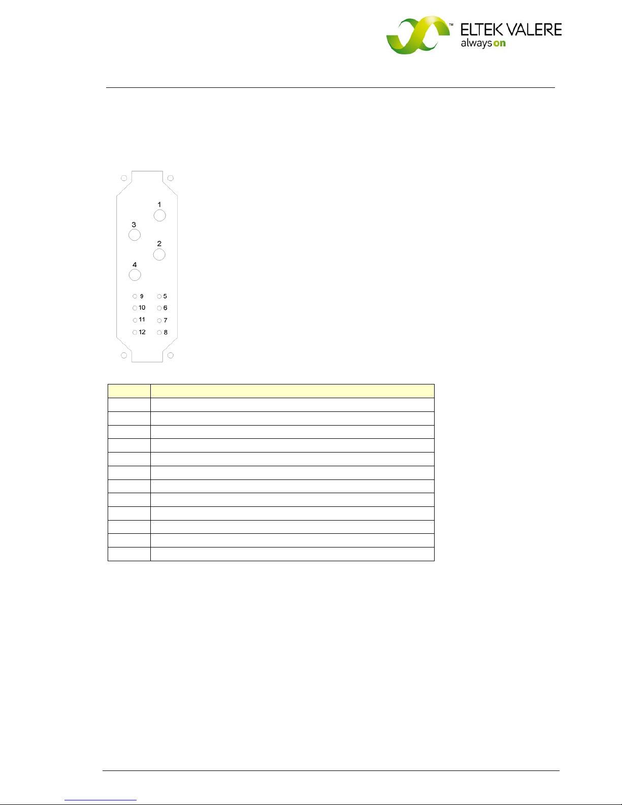
3.3.1 Electrical Connector X1 for UNV-F 2.5 – 3.3kVA, UNV60-5.0F and UNV110-5.0F
X1 (HAN-K4/8) socket outlet (DC input voltage / AC output voltage and signalling):
X1/Pin Designation
1 DC input, plus pole
2 AC output, neutral conductor
3 DC input, minus pole
4 AC output, phase L1
5 --6 SYNC-GND (synchronous bus ground)
7 SYNC-SIG* (synchronous bus 50Hz-signal)
8 SYNC-STAT** (synchronous bus state lines)
9 --10 Collective failure COM***
11 Collective failure OK (normally open=NO)
12 Collective failure error (normally closed=NC)
The maximum allowed load for the relay contacts is:
@ V= 110V / I< 0.45A
DC
@ V 60V
DC / I< 1ADC
*In parallel operation the contacts SYNC – GND and SYNC – SIG of each inverter have to be wired.
**In operation with an UNB it is necessary to interconnect the synchronization bus (contacts SYNC – GND, SYNC
– SIG and SYNC – STAT) between the inverter(s) and the UNB.
***Potential free relay contact with safe electrical separation to the AC and DC side; in case of failure COM and
NC are closed.
 Loading...