

Page 1
357100.013
Solar Grid-Tie Inverters
2.1kW to 4.6kW
User’s Guide
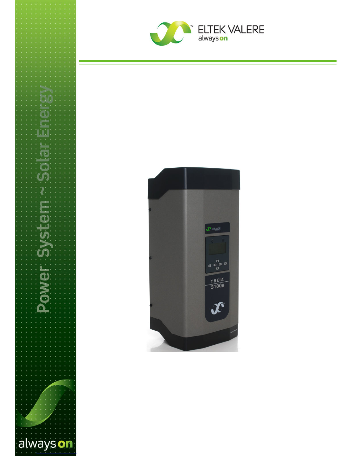
THEIA S
String Inverters
Page 2
2 User’s Guide THEIA S String Inverters 357100.013, Issue 2.0, 2010 Aug
Information in this document is subject to change without notice and does not represent a
commitment on the part of Eltek Valere.
No part of this document may be reproduced or transmitted in any form or by any means —
electronic or mechanical, including photocopying and recording — for any purpose without the
explicit written permission of Eltek Valere.
Copyright ©:
Eltek Valere
, 2011
357100.013 Issue 2.0, 2010 Aug
Published 2010-08-27
MfH
NS-EN ISO 14001 Certified
Certificate No:
11276-2007-AE-NOR-NA
NS-EN ISO 9001 Certified
Certificate No:
4072-2007-AQ-NOR-NA
Page 3

User’s Guide THEIA S String Inverters 357100.013, Issue 2.0, 2010 Aug 3
Table of Contents
1. Symbols ....................................................................................... 4
Warning Notices .............................................................................................. 4
2. Safety, Dangers and Intended Use ............................................ 5
3. Function ....................................................................................... 6
Variants ........................................................................................................... 6
Options ........................................................................................................... 6
4. Installation ................................................................................... 7
Scope of delivery ............................................................................................ 7
Unpacking ....................................................................................................... 7
Mounting the Inverter ...................................................................................... 8
Connecting the Inverter ................................................................................. 11
5. Startup ........................................................................................ 17
Initial Startup of a Single Inverter .................................................................. 18
Replacing Devices ........................................................................................ 22
6. Operation ................................................................................... 24
DC Disconnector ........................................................................................... 24
Display and Operation .................................................................................. 25
Standard Display ........................................................................................... 27
Main Menu .................................................................................................... 27
Operating Display ......................................................................................... 28
Settings ......................................................................................................... 31
Information .................................................................................................... 37
Error Display ................................................................................................. 41
7. Service ........................................................................................ 44
Service Menu ................................................................................................ 44
8. Maintenance ............................................................................... 48
Maintenance ................................................................................................. 48
Cleaning ........................................................................................................ 49
9. Placing Out of Operation .......................................................... 50
Dismounting .................................................................................................. 50
Return Consignment ..................................................................................... 51
10. Disposal ..................................................................................... 53
11. Troubleshooting ........................................................................ 54
Table of events ............................................................................................. 54
12. Standards and Approvals ......................................................... 56
13. Technical Data ........................................................................... 57
14. EU Declaration of Conformity .................................................. 59
15. Warranty for
THEIA S
................................................................ 60
Page 4
4 User’s Guide THEIA S String Inverters 357100.013, Issue 2.0, 2010 Aug
1. Symbols
Warning Notices
Classification of warning notices
The warning notices differentiate between three types of dangers indicated by the
following signal words:
• Caution warns of material damage
• Warning warns of bodily harm
• Danger warns of a danger to life
Layout of the warning notices
Type and source of the danger!
• Action to avoid the danger
Signal words
Page 5

User’s Guide THEIA S String Inverters 357100.013, Issue 2.0, 2010 Aug 5
2. Safety, Dangers and Intended Use
Use inverters according to their intended use.
Use inverters in original and technically fully intact condition without unauthorized
modifications.
Ensure that inverters are installed and serviced by qualified specialists only.
The qualified specialist personnel requires a license from the relevant energy
suppliers.
Always mount inverters in a vertical position.
Ensure that all protection devices are fully operational.
Verify that ventilation openings are not blocked or covered.
Protect inverters from direct sunlight.
Prior to installation and maintenance work, make certain that the inverter is de-
energized.
Ensure that regulations stipulated by trade associations and inspection authorities
and agencies are observed and that the connection conditions of the relevant energy
supplier or equivalent national and international rules and regulations are adhered
to.
Observe conditions of use (see Chapter 13 Technical Data).
Use the inverter exclusively to feed photovoltaically converted solar energy into the
public 230 V/50 Hz mains.
Use the inverter exclusively in buildings or weatherproof places.
Do not use the inverter in autonomous power systems.
Do not use the inverter in vehicles.
Page 6

6 User’s Guide THEIA S String Inverters 357100.013, Issue 2.0, 2010 Aug
3. Function
Variants
The THEIA S String inverter line includes the following variants with different power
ranges (see Chapter 13 Technical Data):
• 2100 S
• 2800 S
• 3100 S
• 3800 S
• 4300 S
• 4301 S
• 4600 S
• 4601 S
Possible options:
• 3-phase ENS (5-pole AC terminal)
with DC disconnector, or
without DC disconnector
or
• 1-phase ENS-EPT (3-pole AC terminal)
with DC disconnector, or
without DC disconnector
Options
Upgrades for an inverter or an inverter system:
• Inverter networking via EIA485 bus. Much easier and more comprehensive input
and monitoring options.
• Optical and acoustical indicator (warning) devices.
• Remote monitoring or remote readout with Webmaster
• Central display of systems with Viewmaster
• Evaluation of system data with PV-Monitor
Page 7
User’s Guide THEIA S String Inverters
357100.013, Issue 2.0, 2010 Aug
7
4. Installation
Scope of delivery
•
Inverter
•
Mounting fixture
•
Operating manual
•
Wieland RST 5i plug connector (3-phase ENS)
or
•
Wieland RST 3i plug connector (1-phase ENS-EPT)
Unpacking
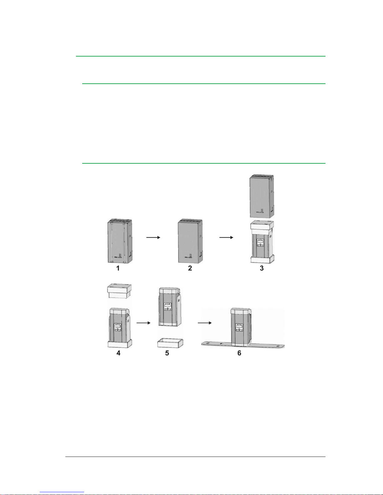
Unpack the inverter as follows:
1. Put the box in vertical position according to box markings.
2. Cut packing straps without damaging the box.
3. Remove the cardboard sleeve.
4. Remove the lid pad.
5. Hold the inverter at the grip openings and lift it out of the base pad.
6. Put down the inverter.
Page 8
8 User’s Guide THEIA S String Inverters 357100.013, Issue 2.0, 2010 Aug
Mounting the Inverter
Note:
Eltek Valere
advises against installing the inverter in living spaces.
Danger to life due to electric shock!
• Have the inverter opened only by Eltek Valere service peronnel, or
service partners authorized by Eltek Valere.
Danger
Danger to life due to incorrect connection of inverter!
• Have inverters installed by qualified specialists only. The qualified
specialist personnel requires a license from the relevant energy suppliers.
Danger
Danger to life due to inverter dropping from the wall!
• Use mounting elements appropriate for the mounting wall and the weight
of the inverter unit.
• Wear protective footwear when mounting and dismounting inverters.
Danger
Material damage due to unprotected installation site!
• Always protect inverters with a protective roof when installing them
outdoors.
• Observe admissible ambient temperature (see
Chapter 13 Technical
Dat
a
)
.
Caution
Material damage due to excessive dust formation!
• Protection Type IP54 does not apply to the interface card.
• Avoid excessive dust formation.
• Avoid dust formation with electrically conductive dust particles.
Caution
Page 9
User’s Guide THEIA S String Inverters 357100.013, Issue 2.0, 2010 Aug 9
Mounting Fixture
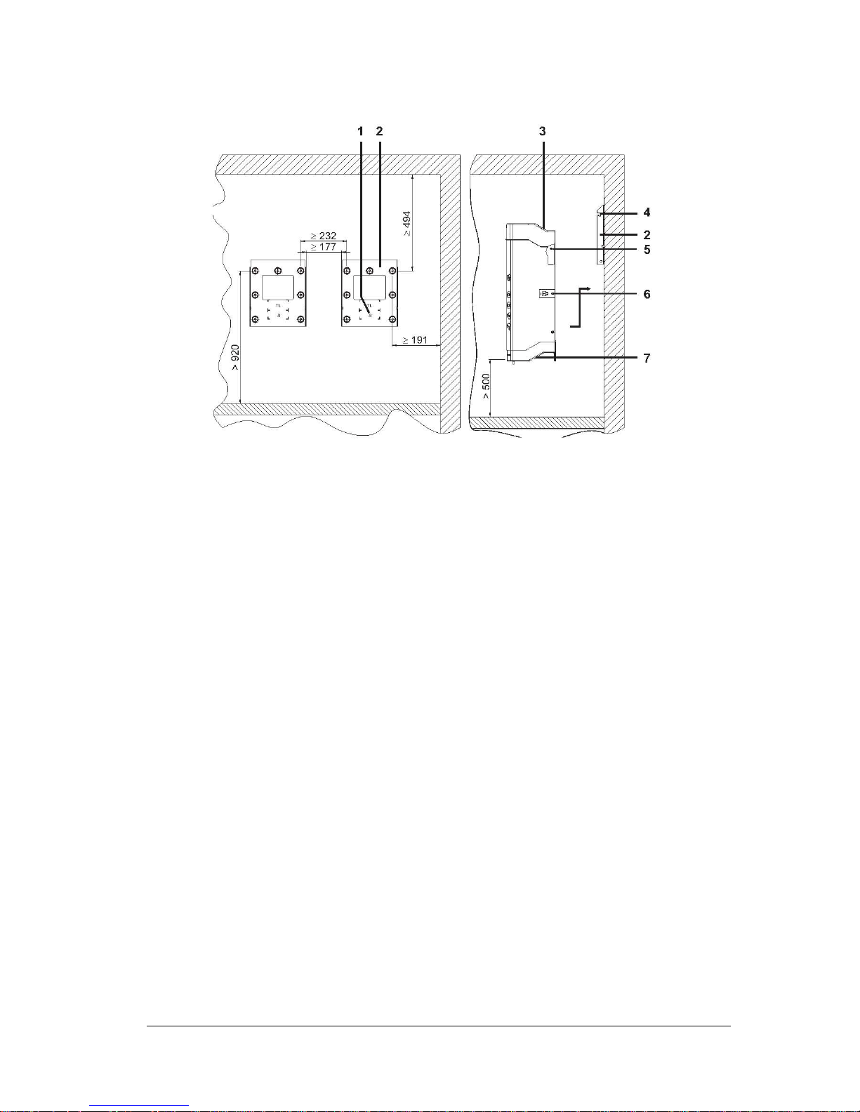
Figure 1 Distances for mounting fixture positioning
(1) Display position
(2) Mounting fixture
(3) Ventilation openings
(4) Slotted piece for mounting bolts
(5) Mounting bolts
(6) Locking screw
(7) Grip moldings
Install the mounting fixture as follows:
• Unscrew mounting fixture (2) from the back of the inverter
- Two locking screws secure the inverter in the mounting fixture
- The locking screw (6) is marked by a paper strip with a lock symbol. The
locking screw is longer than the other housing screws
- Do not remove the paper strip
• Mark the mounting holes using the mounting fixture as a template
- Observe dimensions and distances
- Observe a minimum distance of 50cm to the floor
- The display position (1) is stamped into the mounting fixture (2)
- The display position for the THEIA S series is marked with an
‘S’
• Drill the mounting holes and insert the screw anchors
• Bolt down mounting fixture (2)
Page 10
10
User’s Guide THEIA S String Inverters
357100.013, Issue 2.0, 2010 Aug
Inverter
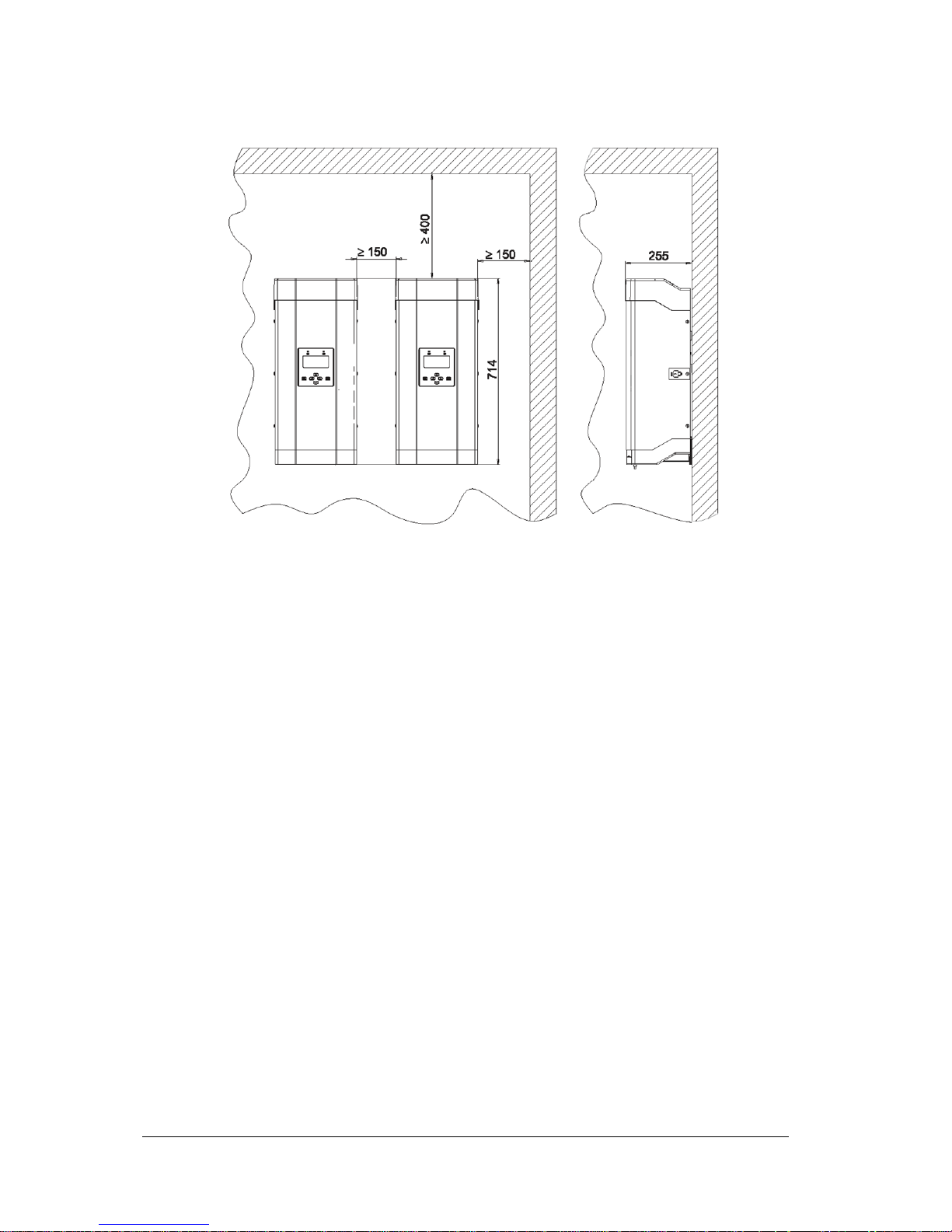
Figure 2 Spacing between mounted inverters
Mount inverters as follows:
• Observe a minimum distance of 50cm to the floor
• Slide the inverter heat sink into mounting fixture (2). Use the outer cooling fins as
guides in mounting fixture (2).
• Hold the inverter at molded grips (7) and push up until mounting bolts (5) drop into
slotted pieces (4) on both sides.
• Gently let down the inverter.
With the mounting bolts (5) seated in the slotted pieces.
• Verify that minimum distances are kept (see Figure 2)
• Verify that the inverter is hanging in the mounting fixture correctly
• Secure the inverter by inserting and tightening the locking screw (6) in the marked
position (paper strip)
• Ensure that the locking screw (6) is accessible for the dismounting of the inverter
Page 11
User’s Guide THEIA S String Inverters 357100.013, Issue 2.0, 2010 Aug 11
Connecting the Inverter
Danger to life due to high AC voltage!
• Switch off the mains power supply (AC side, fuse) before connecting the
inverter.
Danger
Danger to life due to high AC voltage!
• Verify that galvanic isolation between the photovoltaic generator circuit
and the AC circuit is maintained by the way the cables are run.
Danger
Danger to life due to high DC voltage!
• Prior to connecting the inverter, verify that voltage is applied to the
generator-side DC terminal
• Prior to connecting the inverter, verify that the DC voltage polarity is
correct
• Wear insulating protective clothing and face protection if there is voltage
present at the DC input
• Remove DC cable exclusively when inverter is out of operation
Danger
Lack of performance and functionality due to inappropriate cables!
• Ensure that wire cross sections and fuses conform to VDE 100 Part 430,
or the equivalent local standard.
• Ensure that any network cables between two inverters are no longer than
30m
• For DC cables, use a wire cross section of at least 2.5mm
2
• Ensure that the AC cable resistance does not exceed 0.5Ω
Caution
Material damage due to excessive voltage!
• Ensure that the max. DC voltage is not exceeded (see
Chapter 13
Technical Data
)
• Connect exclusively safety extra low voltage (SELV) on the contacts of
the external indicator
Caution
Page 12
12 User’s Guide THEIA S String Inverters 357100.013, Issue 2.0, 2010 Aug
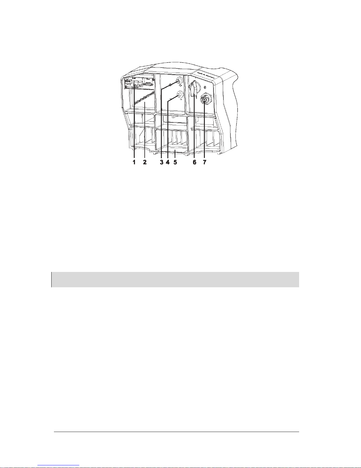
Terminal Side: 3-Phase ENS
Figure 3 Inverter Terminal Side: 3-phase ENS
(1) Network terminals
(2) Safety sticker
(3) DC terminal +
(4) DC terminal –
(5) Type plate
(6) Switch knob DC disconnector (optional)
(7) AC terminal
Note:
THEIA 3800S, 4300S, 4301S, 4600S
and
4601S
inverters have two pairs of DC terminals. These DC terminals are
internally paralleled.
Page 13
User’s Guide THEIA S String Inverters 357100.013, Issue 2.0, 2010 Aug 13
AC Terminal: 3-Phase ENS
The Wieland RST 5i plug connector for the DC terminal is supplied with the inverter.
Figure 4 Wiring diagram (terminal side)
(1) N
(2) PE
(3) L1 (feed phase)
(4) L2
(5) L3
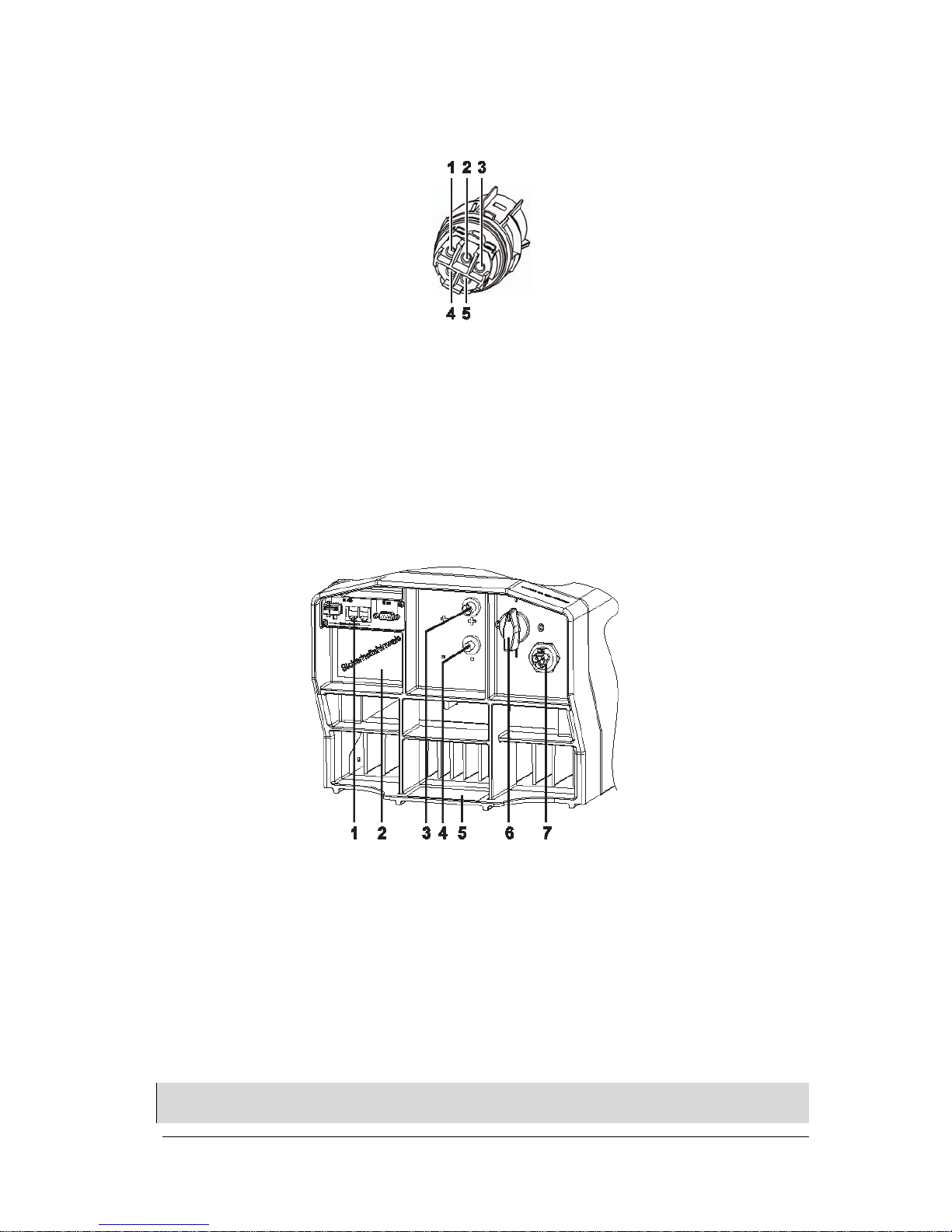
Terminal Side: 1-Phase ENS
Figure 5 Inverter Terminal Side: 1-phase ENS
(1) Network terminals
(2) Safety sticker
(3) DC terminal +
(4) DC terminal –
(5) Type plate
(6) Switch knob DC disconnector (optional)
(7) AC terminal
Note:
THEIA 3800S, 4300S, 4301S, 4600S
and
4601S
inverters have two pairs of DC terminals. These DC terminals are
internally paralleled.
Page 14
14 User’s Guide THEIA S String Inverters 357100.013, Issue 2.0, 2010 Aug
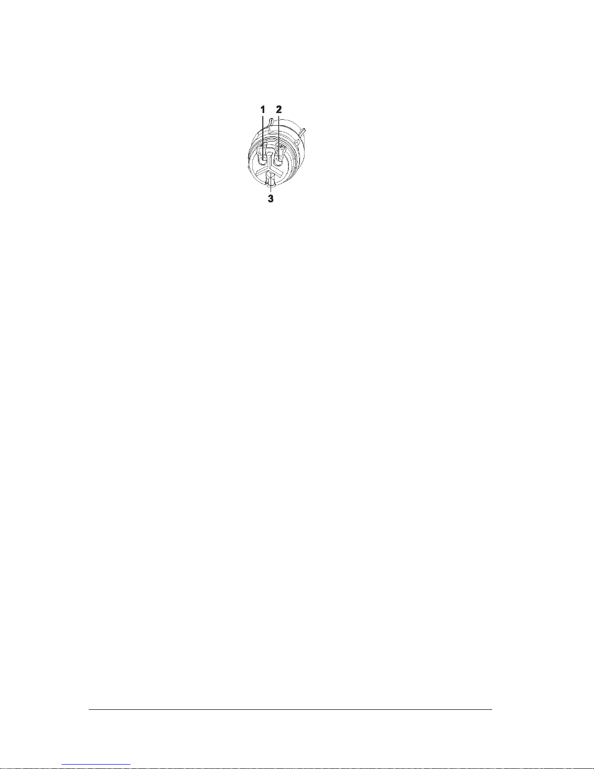
AC Terminal: 1-Phase ENS
The Wieland RST 3i connector plug intended for the AC terminal is enclosed.
Figure 6 Wiring diagram (terminal side)
(1) N
(2) L1 (feed phase)
(3) PE
When connecting several inverters:
• Distribute inverters evenly (as regards their power) between phases of the mains
supply
AC Voltage Connection
Establish AC voltage connection as follows:
• Establish a connection to the power supply system with a cable on the AC terminal
as follows:
- with the Wieland RST 5i plug connector (3-phase ENS) supplied with the system,
or
- with the Wieland RST 3i plug connector (1-phase ENS) supplied with the system.
• Fuse the AC output with a fuse rating of not more than 25A
• Use lines matching the type-dependent AC
• Mind different terminals for connection to AC mains power supply depending on
whether 1-phase ENS or 3-phase ENS is used
DC Voltage Connection
Establish DC voltage connection as follows:
• Establish a connection to the solar panel on the DC input with a cable with a DC
plug connector
• If more than one strand is connected, ensure that the number and type of solar
modules and the PV power are identical for every strand
Page 15
User’s Guide THEIA S String Inverters
357100.013, Issue 2.0, 2010 Aug
15
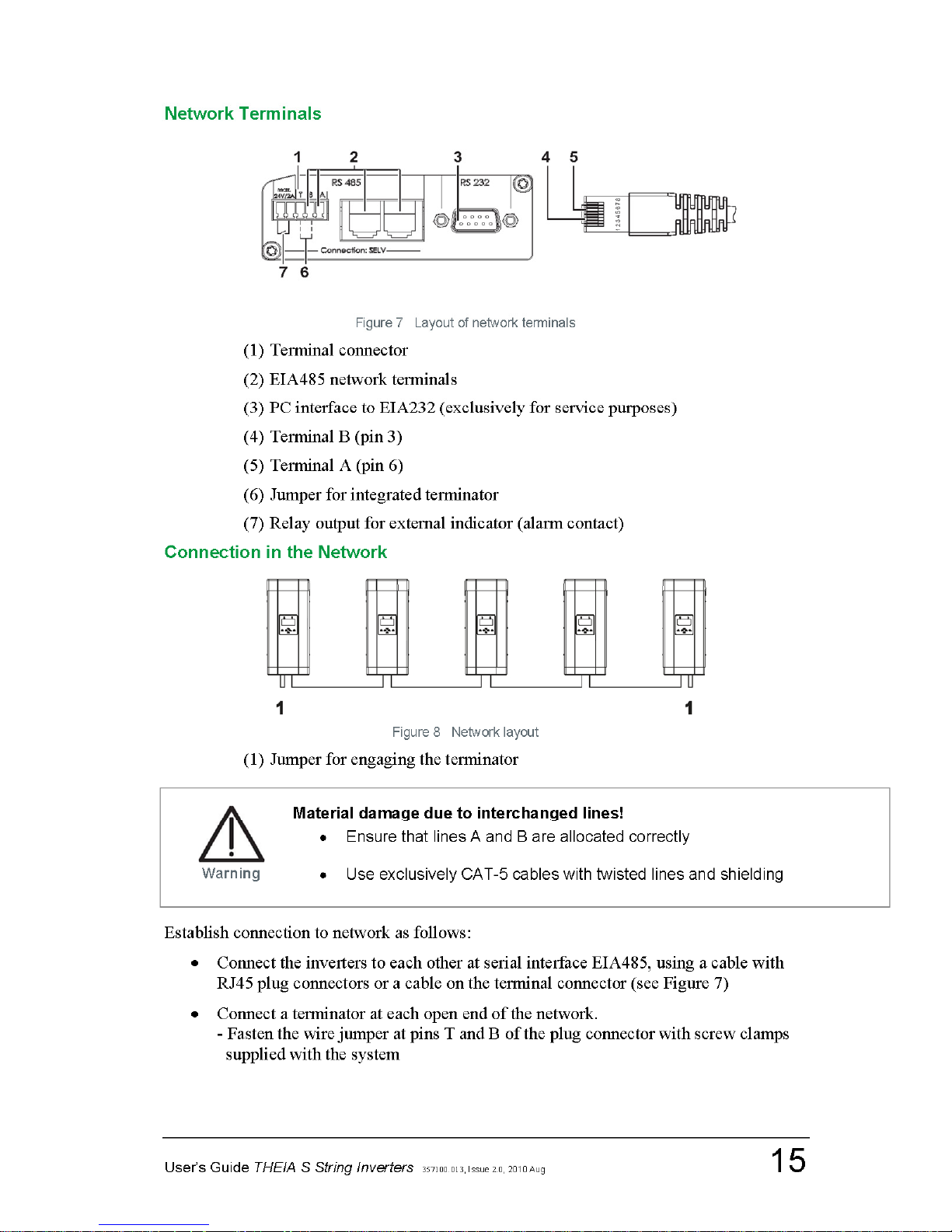
Network Terminals
Figure 7 Layout of network terminals
(1) Terminal connector
(2) EIA485 network terminals
(3) PC interface to EIA232 (exclusively for service purposes)
(4) Terminal B (pin 3)
(5) Terminal A (pin 6)
(6) Jumper for integrated terminator
(7) Relay output for external indicator (alarm contact)
Connection in the Network
Figure 8 Network layout
(1) Jumper for engaging the terminator
Establish connection to network as follows:
• Connect the inverters to each other at serial interface EIA485, using a cable with
RJ45 plug connectors or a cable on the terminal connector (see Figure 7)
• Connect a terminator at each open end of the network.
- Fasten the wire jumper at pins T and B of the plug connector with screw clamps
supplied with the system
Page 16

16 User’s Guide THEIA S String Inverters 357100.013, Issue 2.0, 2010 Aug
Alarm Contact
• Connect any external indicator device to the potential-free contact.
- When an error is detected, the contact is closed and activates the indicator device
(optical or acoustic warning)
- Setting: see menu Settings → function Alarm contact
• Only use safety extra low voltage (SELV) of max. 24 V as supply voltage
Page 17
User’s Guide THEIA S String Inverters
357100.013, Issue 2.0, 2010 Aug
17
5. Startup
Note:
Independent of demand, the inverter activates the fan as soon as power input is started (e.g. every morning). When
feeding in, the inverter activates the fan as required.
During the startup, several basic settings such as language selection, date and time settings
are set.
If several inverters are installed which are networked via the EIA485 interface, the startup
can be carried out at any one of the installed inverters (master programming). This inverter
transmits the configuration settings to all other inverters in the network. Every inverter is
automatically assigned a number at its initial startup. The free allocation of this number is
possible in a further step.
The inverters that are not used for input entries display other screen contents depending on
the menu. If no entry is possible, the inverter shows the start screen.
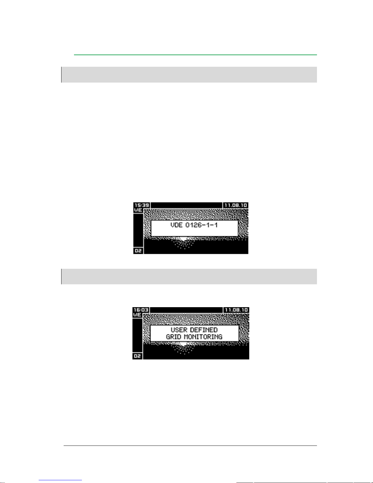
Start screen
All inverters that are not operated during the configuration will show the blocking screen.
Note:
If parameters of the inverter have been adapted to special requirements of the energy supplier, this is indicated on
the start screen.
After changing parameters, the inverter shows the following screen:
Page 18
18
User’s Guide THEIA S String Inverters
357100.013, Issue 2.0, 2010 Aug
Initial Startup of a Single Inverter
• Switch on the main power supply (fuse)
For inverters with DC disconnector:
• Set switch knob to ‘1’
The inverter is supplied with power. Configuration through the following dialogs.
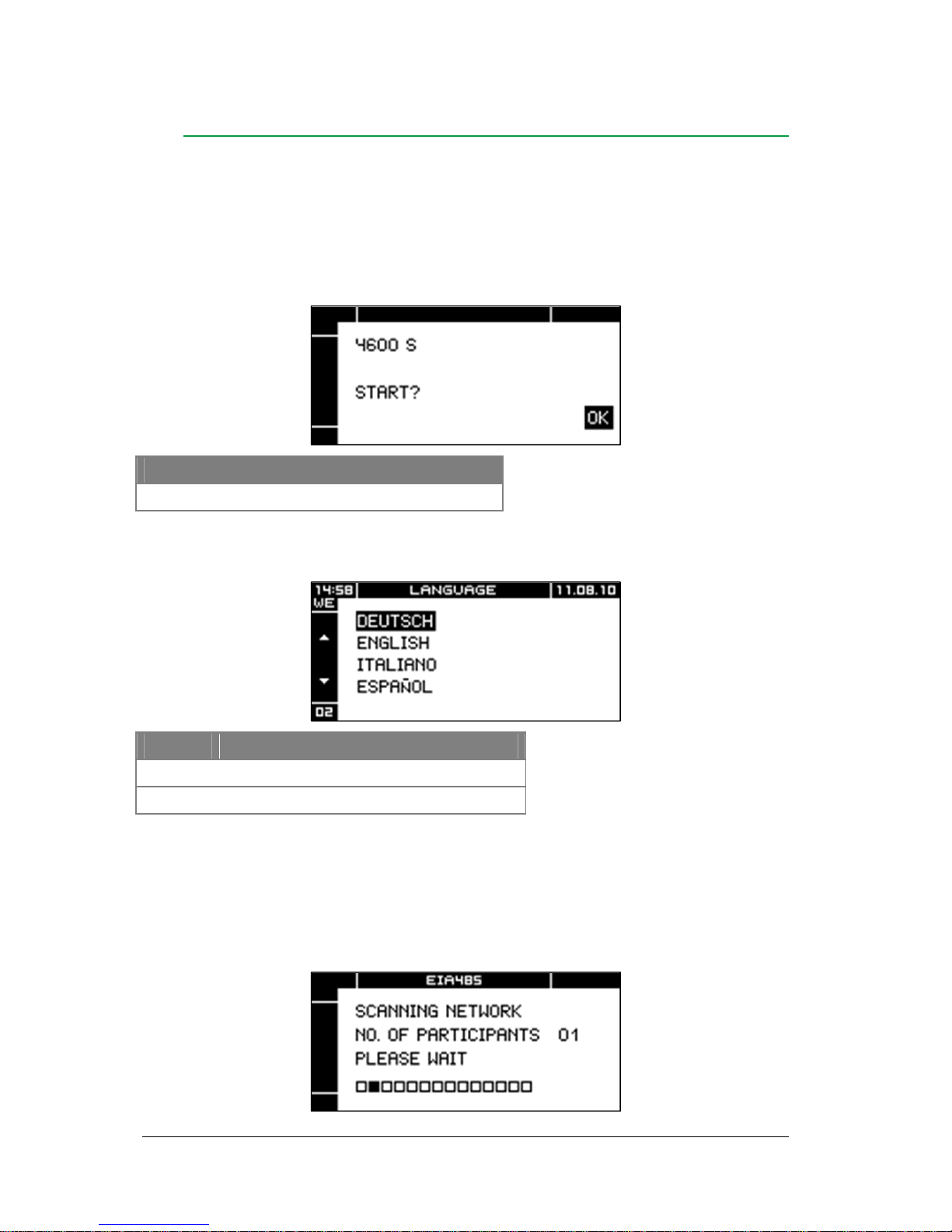
Start initial startup
Key Function
OK
Start configuration process with this inverter
Language selection
Key Function
Select language
OK
Accept selected language
After the configuration process has been started:
- The inverter scans the network connected by the EIA485-Bus for other inverters.
- All other inverters connected to the network are blocked.
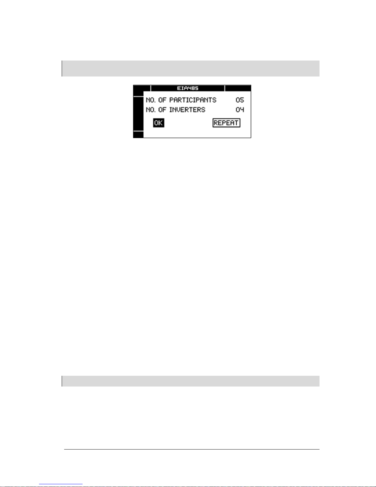
EIA485 bus
As long as the network scan (Scanning Network) is still in process, the display shows the
following screen:
Page 19
User’s Guide THEIA S String Inverters
357100.013, Issue 2.0, 2010 Aug
19
When the network scan is completed, the display shows the number of detected bus
participants. In case of a single inverter, the display shows 01.
Note:
The network scan can only recognize more than 1 inverter if the inverters are correctly networked via the EIA 485
interface.
If the number of detected bus participants (e.g. inverters, data loggers, etc.) does not agree
with the installation:
• Select REPEAT
• Press OK key
• Check connections (EIA485 interfaces) if required
If the number of detected bus participants is in agreement with the installation:
• Select OK
• Press OK key
In case of a single inverter:
— Screen Date appears
In case of several networked inverters:
— Screen Inverter numbering appears
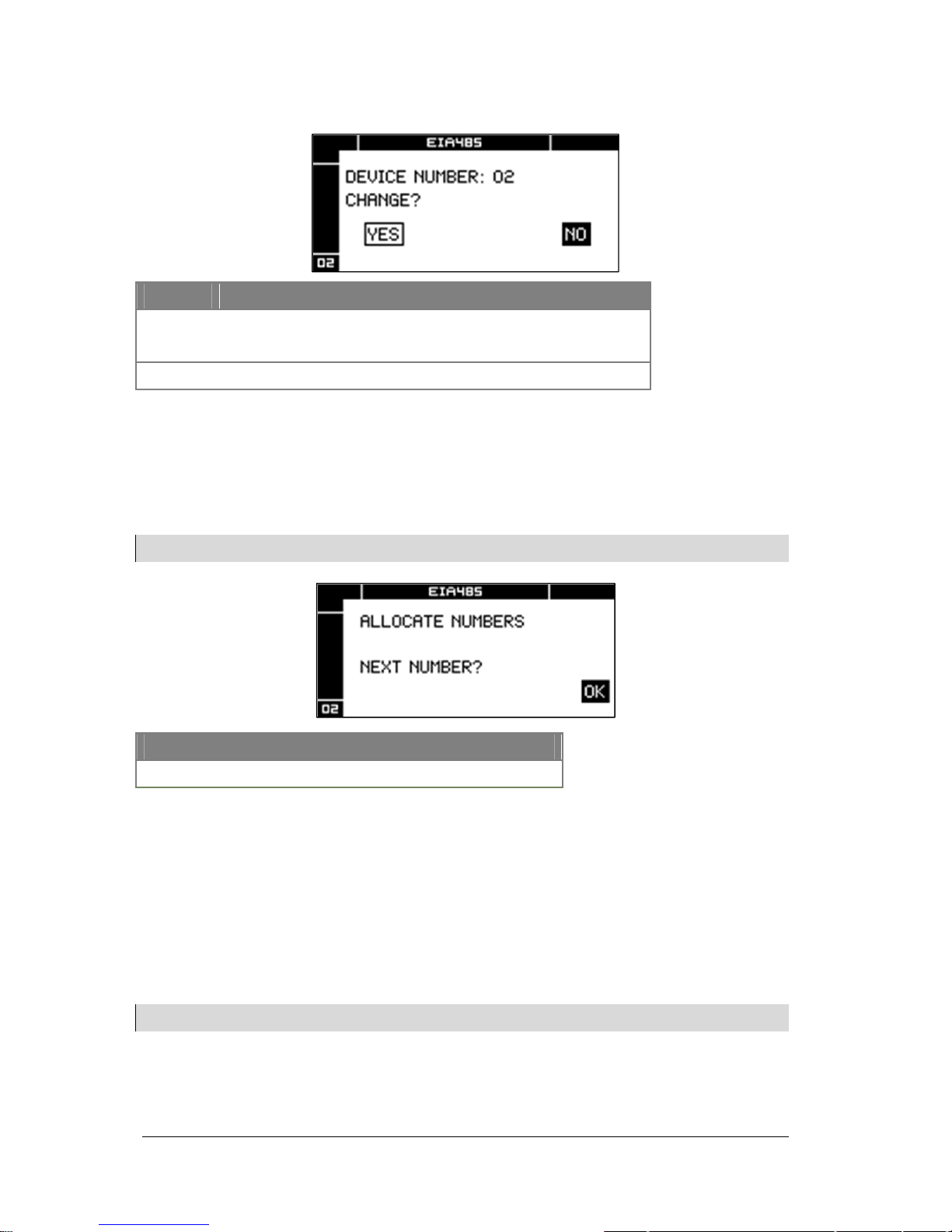
Inverter numbering
It is possible to network several inverters via the EIA485 interface. Inverter numbers are
allocated automatically during the network scan. The inverter number is displayed in the
lower left corner of the screen.
For a clearer overview, the inverters can be re-numbered for specific requirements. For
instance, the inverter number can be defined according to the installation sequence.
Example: With three inverters installed, the left one can be allocated the no. 1, the middle
one can be no. 2 and the right-hand one no. 3.
Note:
The following screen is not displayed if only one inverter is configured.
Page 20
20
User’s Guide THEIA S String Inverters
357100.013, Issue 2.0, 2010 Aug
Screen Inverter numbering:
Key Function
YES = Allocate user-defined number to inverter
NO = Accept inverter number unchanged
OK
Confirm selection
If NO was selected:
— The inverter adopts the displayed number und switches to the Settings Date screen
If YES was selected:
— The display shows the following screen
Note:
The following screen is not displayed if only one inverter is configured:
After OK was selected:
• Allocate numbers to inverters in the required sequence
— The inverter adopts the next available number
— The display shows the following screen:
Example:
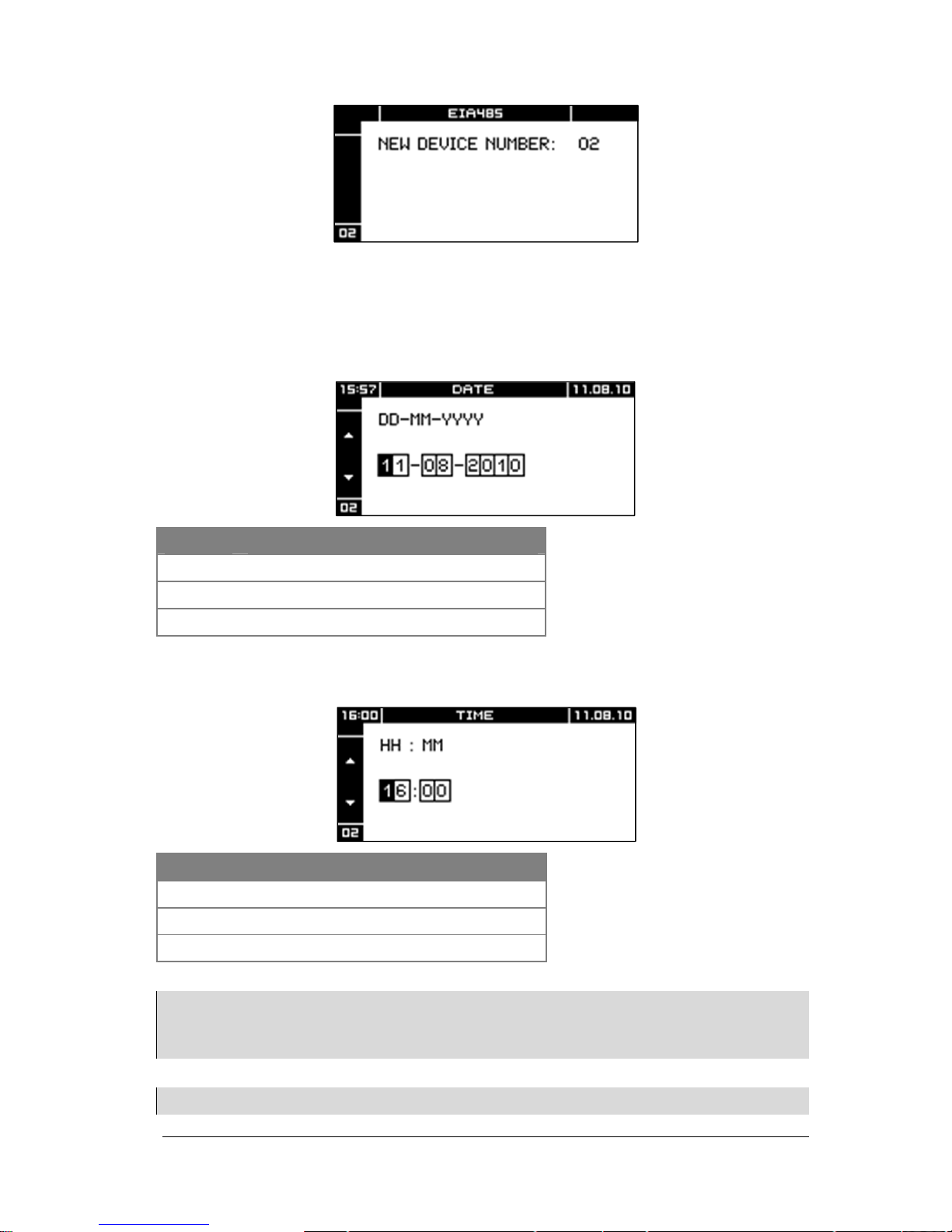
As soon as the OK key was pressed at the first inverter, this inverter is allocated no. 1,
which is shown on the display. When the OK key was pressed at the second inverter, this
inverter is allocated no. 2, etc…
Note:
The following screen is not displayed if only one inverter is started up.
Key Function
OK
The inverter adopts the next available number
Page 21
User’s Guide THEIA S String Inverters
357100.013, Issue 2.0, 2010 Aug
21
— Entry only at one inverter. All other inverters connected to the network are blocked
— With the number allocation completed, the inverter switches to the Date screen
Date
Key Function
Increment or decrement present digit
Select next or previous digit
OK
Accept date setting
Time
Key Function
Increment or decrement present digit
Select next or previous digit
OK
Accept time setting
Note:
It is possible to connect monitoring devices to the EIA485 bus, for example the Webmaster. If the Webmaster is
connected to the internet, it obtains time and date from a time server. If, during a network scan, the inverter has
recognized a monitoring device with own date and time settings, the inverter accepts these settings as default
settings.
Note:
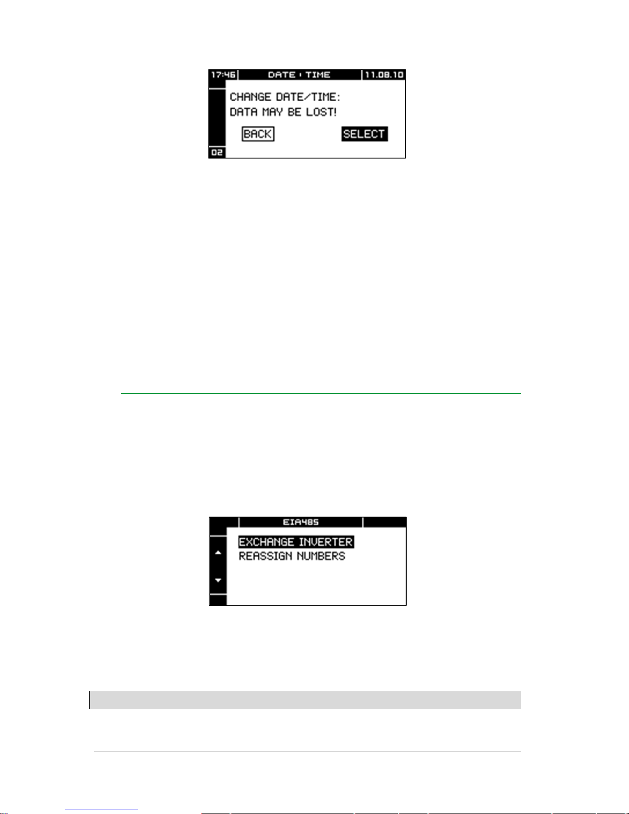
Changing date or time can result in overwriting saved data or cause gaps in data recording.
Page 22
22
User’s Guide THEIA S String Inverters
357100.013, Issue 2.0, 2010 Aug
To accept time setting:
• Select SELECT
• Press OK key
The inverter automatically shares the new time setting with all network participants.
To not accept time setting:
• Select CANCEL
• Press OK key
After setting the time, the configuration (language, date and time) are automatically
transferred to all other inverters in the network (if available).
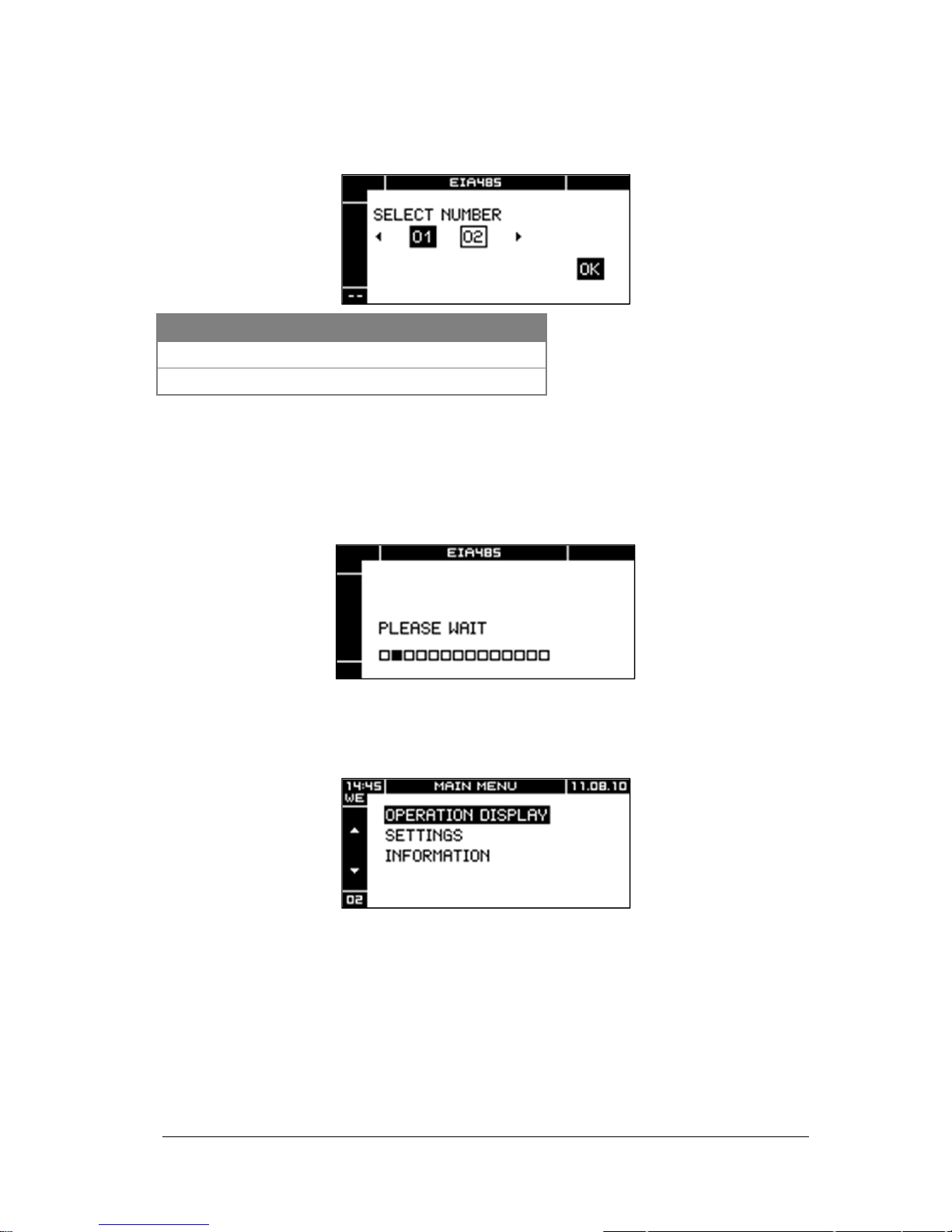
Replacing Devices
If one or more THEIA S inverters in a PV system are replaced, it is possible to maintain the
device numbers of the replaced inverters.
During the network scan, the inverter automatically identifies any replaced devices.
It is possible to either use the old device numbers for the substitute devices or renumber the
devices.
Display and operation are confined to the replaced inverters. All other inverters show the
start screen.
To accept device numbers of replaced inverters:
• Select DEVICE REPLACEMENT
To renumber:
• Select RENUMBERING
Note:
If the device number is already in use, the inverter displays TODO.
Page 23
User’s Guide THEIA S String Inverters
357100.013, Issue 2.0, 2010 Aug
23
Replacement of Devices
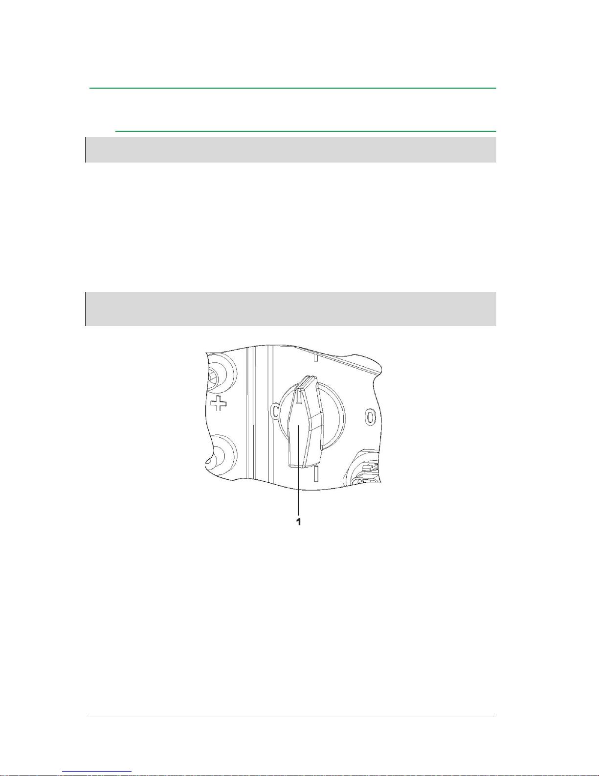
After DEVICE REPLACEMENT was selected, the replaced inverters show the following
screen:
Key Function
Select device number
OK
Accept selected device number
On every replaced inverter:
• Select desired device number
• Press OK key
The inverter automatically transmits the device numbers to all other inverters.
Inverter is added to THEIA S network.
Inverter shows main menu.
Inverter shows device number of the replaced device in the lower left corner.
After device replacement:
• Set date and time
Page 24
24
User’s Guide THEIA S String Inverters
357100.013, Issue 2.0, 2010 Aug
6. Operation
DC Disconnector
Note:
The DC disconnector is exclusively available for variants with DC disconnector. A banderole on the lower part of
the inverter indicates whether a DC disconnector is available.
The DC disconnector enables switching on and off the solar generator.
To engage the solar generator:
• Set DC disconnector to ‘1’
To switch off the solar generator:
• Set DC disconnector to ‘0’
Note:
Eltek Valere
recommends to actuate the DC disconnector once a year to prevent the welding of contacts.
Eltek Valere
recommends switching off the mains voltage (AC) before switching off the DC disconnector to
minimize wear and tear of the contacts.
Figure 9 DC disconnector
(1) DC disconnector
Page 25
User’s Guide THEIA S String Inverters 357100.013, Issue 2.0, 2010 Aug 25
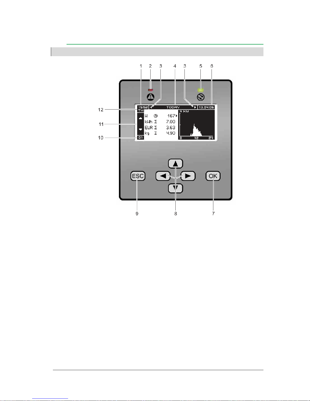
Display and Operation
Note:
If there is no input for approx. 2 minutes, the display switches to the standard default display.
Figure 10 Display and operation
(1) Time
(2) LED red
(3) Scroll arrows horizontal
(4) Title
(5) LED green
(6) Date
(7) OK key
(8) Navigation keys
(9) ESC key
(10) Device number
(11) Scroll arrows vertical
(12) Day
Page 26
26 User’s Guide THEIA S String Inverters 357100.013, Issue 2.0, 2010 Aug
Time
Time display in 24-hour format
LEDs
Two LEDs indicate the operating status of the inverter.
LED red
The LED red indicates the following:
LED green
The LED green indicates the following:
Both LEDs
Both LEDs blinking indicate that the inverter is performing a network scan.
Scroll Arrows
The menu contains other menu items.
• Navigate using keys and , or and .
Title
Title of the selected menu
Date
Date; display format DD.MM.YY.
Keys
The functions of the keys are indicated in the tables under the illustrations.
Device number
Displays the inverter number
Day
Displays the day of the week
Display Operating status
LED off
Normal operation
LED flashes
- Error
- Contact for external indicator closed (depending on selected setting)
Display Operating status
LED on
Power feed on
LED flashes
Preparing for power feed
LED off
Inverter off
Page 27
User’s Guide THEIA S String Inverters
357100.013, Issue 2.0, 2010 Aug
27
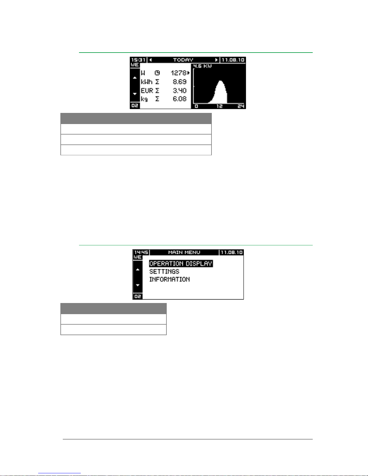
Standard Display
Key Function
Navigate within the display period
Switch to screen Current
ESC
Call up Main Menu
Arrow to the right of the table:
— designation of physical quantity displayed in graphic
Number in the top left corner of the graphic:
— maximum value of scale
— depending on max. DC power of the inverter
Main Menu
Key Function
Navigate within menu
OK
Call up selected menu
To return to main menu from all menus:
• Press ESC repeatedly
Page 28
28
User’s Guide THEIA S String Inverters
357100.013, Issue 2.0, 2010 Aug
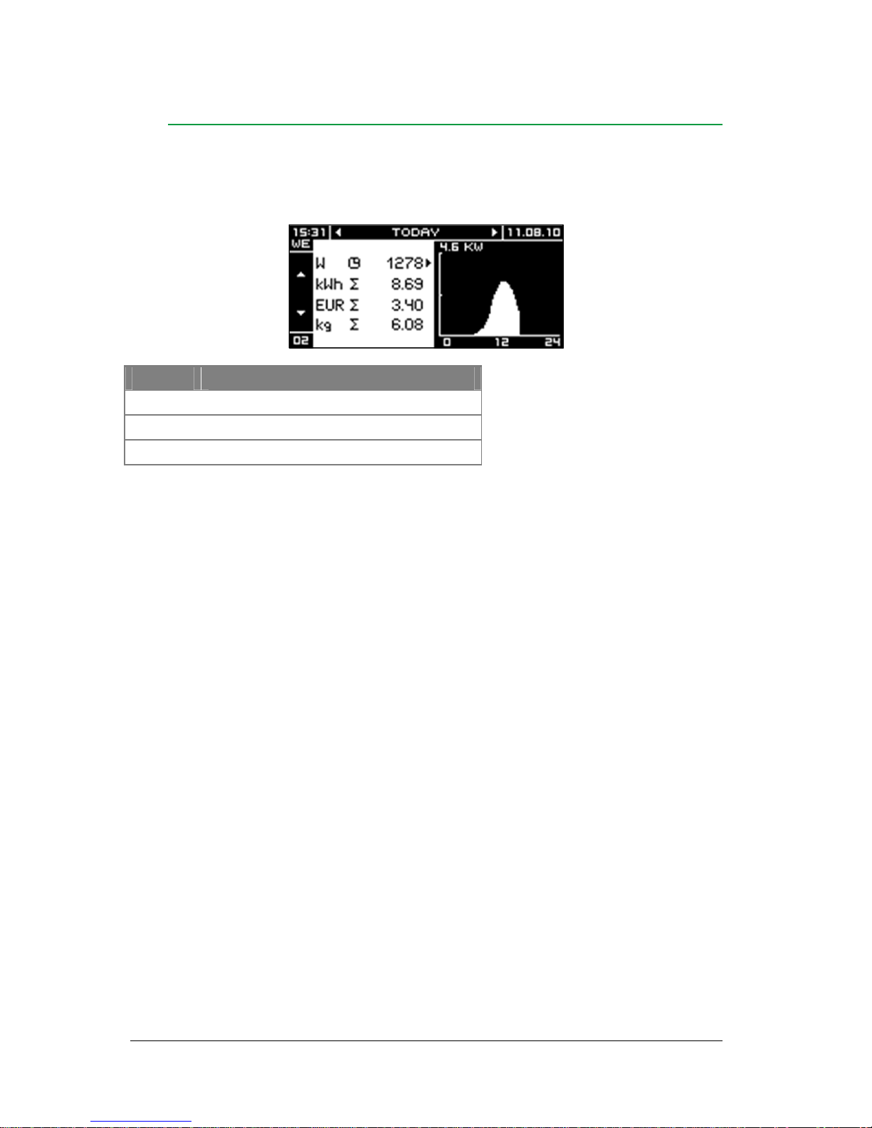
Operating Display
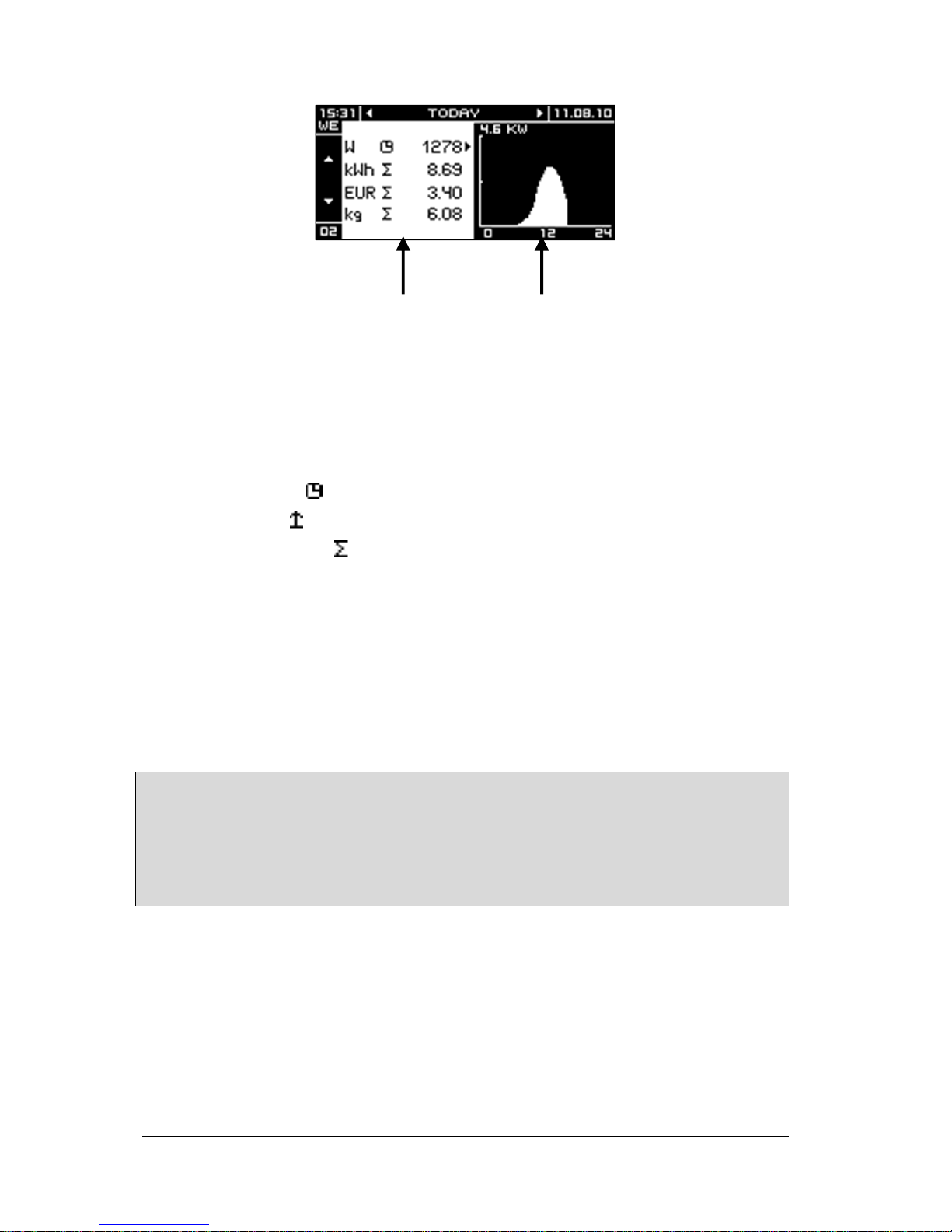
The operating display shows a list with physical quantities and a corresponding graphic
evaluation. Type and value of the displayed physical quantity depend on the selected
period. The illustration below shows an example for the period TODAY.
Arrow to the right of the table:
— designation of physical quantity displayed in graphic
Units:
— W: feed power
— kWh or MWh: feed power for the indicated period
— EUR: rebate for the indicated period (Adjustable in menu Settings.)
— kg: quantity of saved carbon dioxide (CO2)
Number in the top left corner of the graphic:
— maximum value of scale
— dependent on inverter power
Horizontal axis in graphic:
— time scale (e. g. hours of a day)
Key Function
Navigate within the display period
Switch to menu Current
ESC
Back to Main Menu
Page 29
User’s Guide THEIA S String Inverters
357100.013, Issue 2.0, 2010 Aug
29
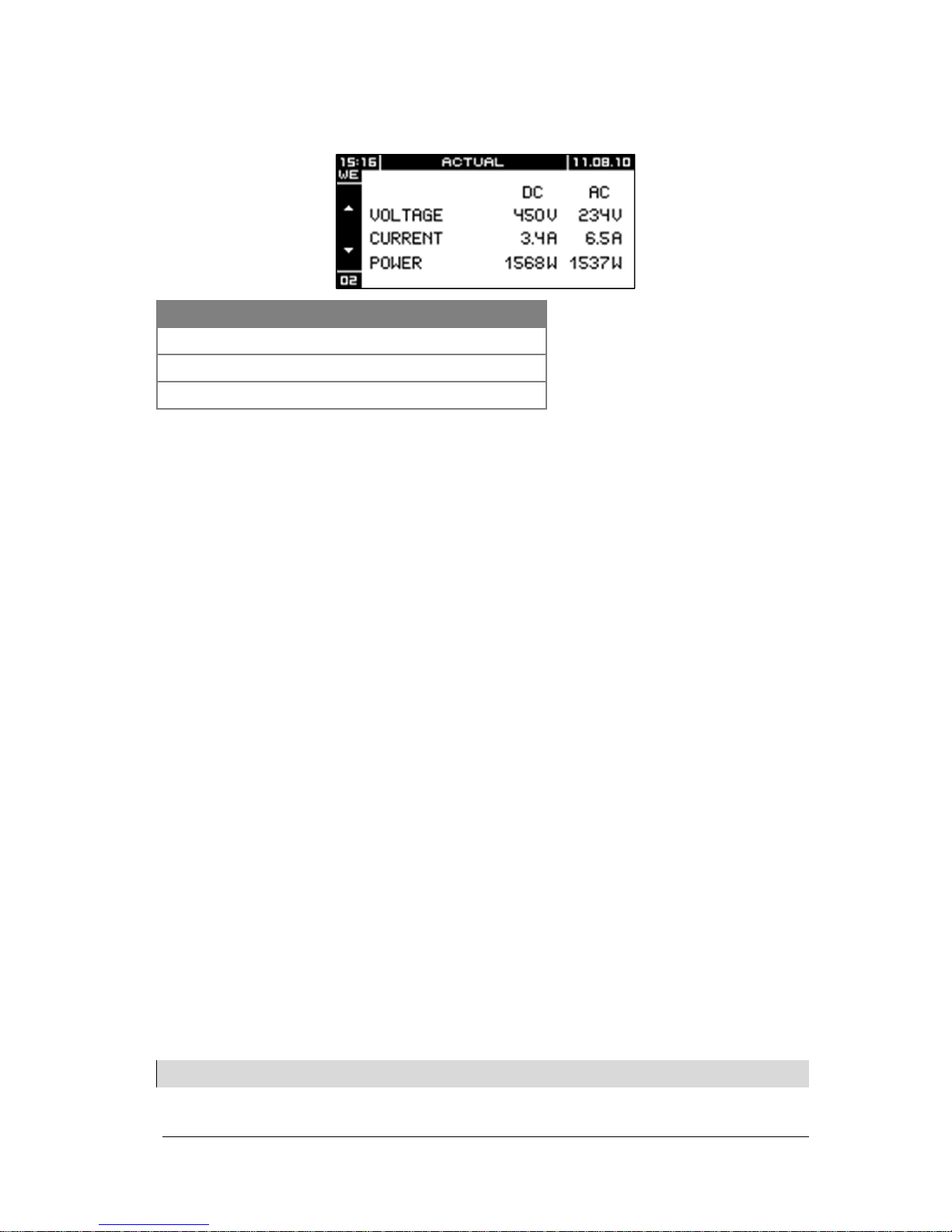
Actual
‘Actual’ shows a list of the current electric values for DC and AC side.
Key Function
Navigate within the display period
Switch to menu Today
ESC
Back to Main Menu
Physical Quantities
The following physical quantities are indicated:
— feed power in W (graphically depicted in the periods TODAY and YESTERDAY)
— feed energy in kWh or MWh (graphically depicted as columns in the periods
WEEK, MONTH and YEAR)
— Rebate in country-specific currency
- Values > 999,000 are displayed as a factor
- Example: 1.234.567 € is displayed as 1.234E6
— CO2 emission reduction in kg or t
— DC and AC voltage
— DC and AC
— DC and AC power
Period
The following display periods can be selected:
— today
— yesterday
— current week
— previous week
— current month
— previous month
— current year
— previous year
— since startup
Note:
The values displayed by the inverter may differ from the readings of calibrated electricity meters.
Page 30
30
User’s Guide THEIA S String Inverters
357100.013, Issue 2.0, 2010 Aug
(1) physical quantities
(2) graphic of physical quantity
Physical quantities:
— Designation of the physical quantity
— current value ( )
— peak value ( )
— cumulative value ( )
Graphic of physical quantity:
— Day: in hours (0 - 24)
— Week: one column per day (Mo. - Su.)
— Month: one column per day
— Year: one column per month (Jan. – Dec.)
Note:
Type and value of the displayed physical quantity depend on the selected period.
Graphic:
For the display periods TODAY and YESTERDAY, the progress of the feed power is displayed. For all other display
periods the feed energy per time interval is displayed.
Table:
For the display period TODAY, the current power value is displayed. For all other periods, the maximum value is
displayed.
2
1
Page 31
User’s Guide THEIA S String Inverters
357100.013, Issue 2.0, 2010 Aug
31
Settings
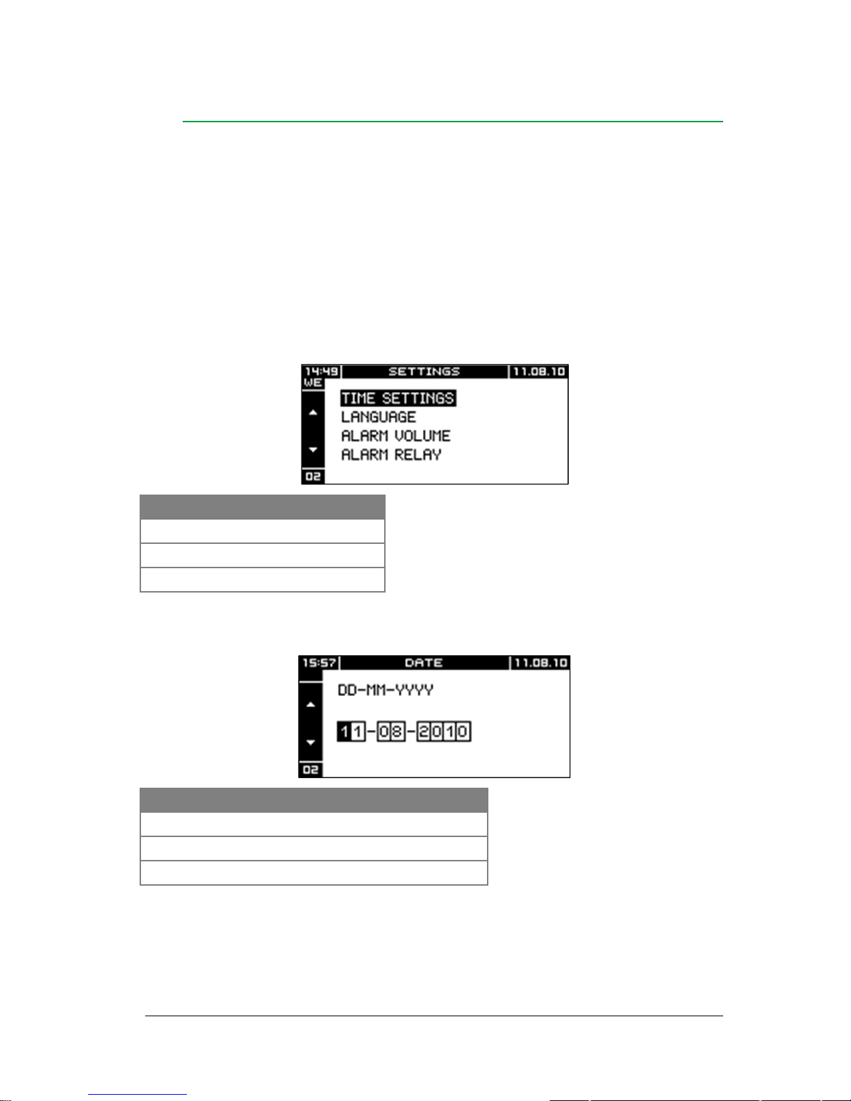
The following settings are possible in the menu Settings:
— Date/time
— Language
— Alarm volume
— Alarm contact function
— LCD
— Rebate
— System
— Energy meter
Key Function
Navigate within menu
ESC
Back to Main Menu
OK
Call up selected menu
Date
Key Function
Increment or decrement present digit
Select next or previous digit
OK
Continue to menu Time
Page 32
32
User’s Guide THEIA S String Inverters
357100.013, Issue 2.0, 2010 Aug
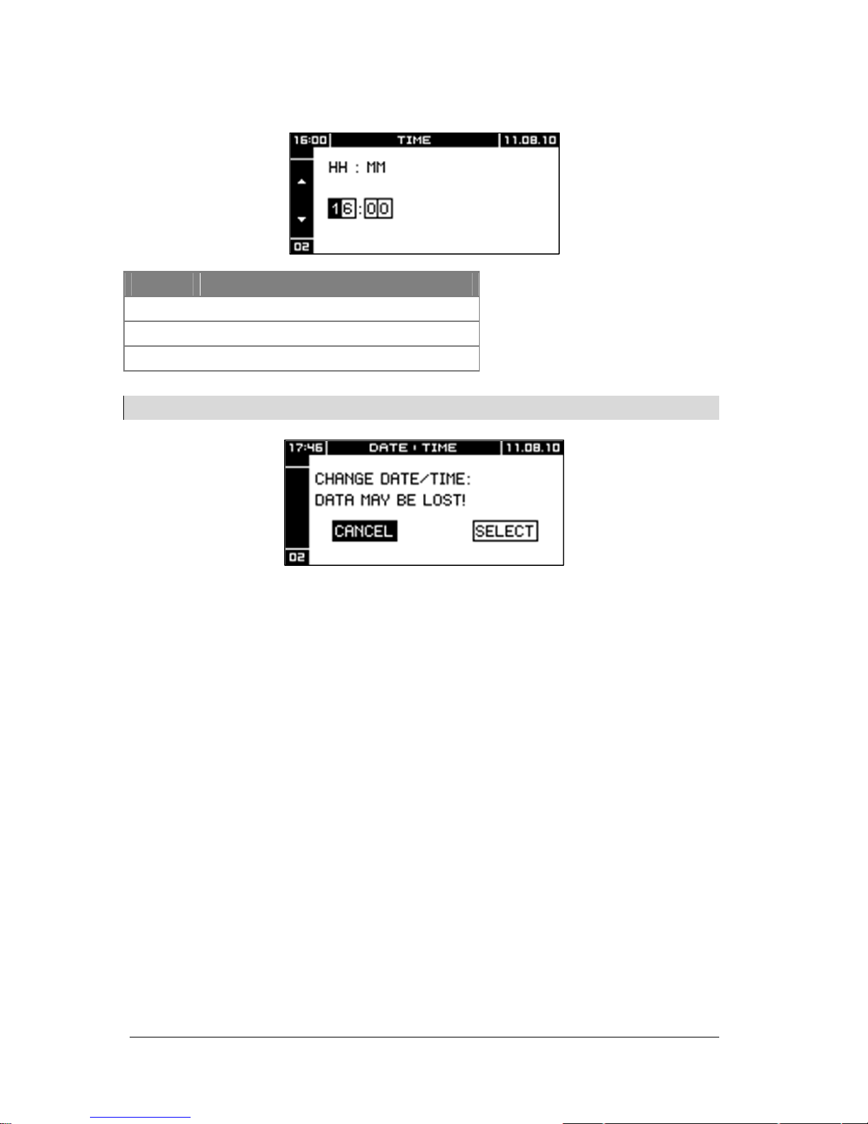
Time
Note:
Changing date or time can result in overwriting saved data or cause gaps in data recording.
To accept time setting:
• Select SELECT
• Press OK key
The inverter automatically shares the new time setting with all network participants.
To not accept time setting:
• Select CANCEL
• Press OK key
Key Function
Increment or decrement present digit
Select next or previous digit
OK
Accept time setting
Page 33
User’s Guide THEIA S String Inverters
357100.013, Issue 2.0, 2010 Aug
33
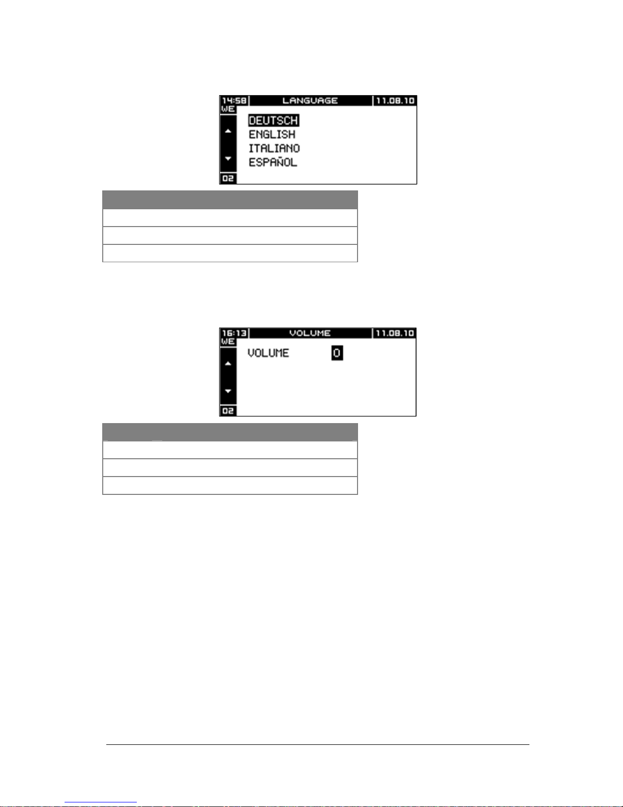
Language
Key Function
Navigate within menu
ESC
Back to menu Settings
OK
Accept selected language
The inverter automatically shares the new language setting with all network participants.
Alarm Volume
Key Function
Increase or reduce alarm volume
ESC
Back to menu Settings
OK
Accept alarm volume setting
The inverter automatically transfers the alarm volume setting to all network participants.
Page 34
34
User’s Guide THEIA S String Inverters
357100.013, Issue 2.0, 2010 Aug
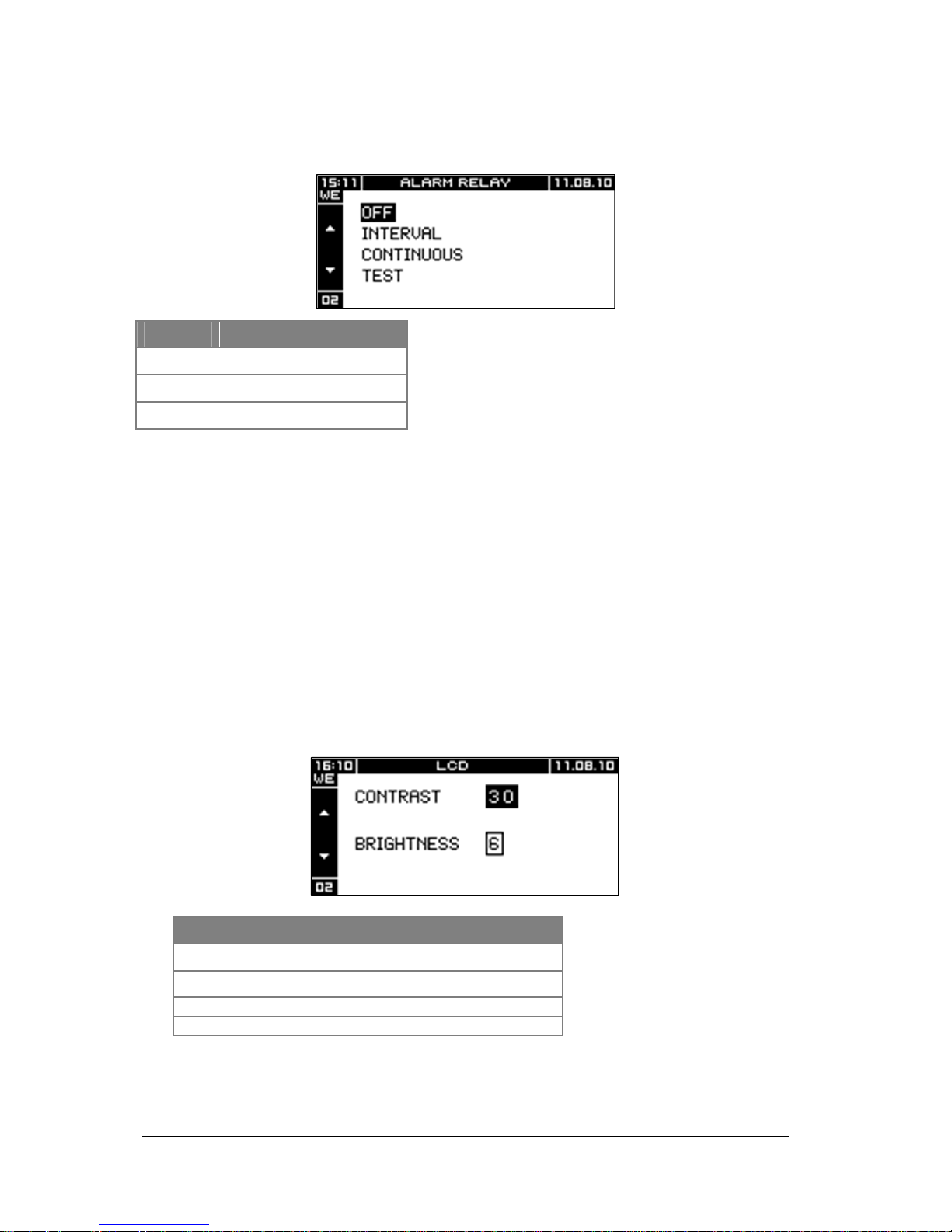
Alarm contact
Key Function
Navigate within menu
ESC
Back to menu Settings
OK
Accept setting
OFF
— The alarm contact is constantly open when a safety-relevant or blocking error
occurs
INTERVAL
— The alarm contact opens and closes periodically when a safety-relevant or blocking
error occurs
DURATION
— The alarm contact is constantly open when a safety-relevant or blocking error
occurs
TEST
— Close the alarm contact momentarily when the OK key is pressed
LCD
Key Function
Increase or reduce contrast or brightness
Navigate between input fields
ESC
Back to menu Settings
OK
Accept setting
Page 35
User’s Guide THEIA S String Inverters
357100.013, Issue 2.0, 2010 Aug
35
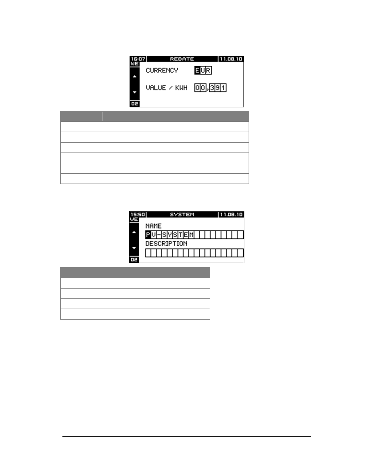
Feed Rebate
Key Function
CURRENCY
Currency in which the rebate is displayed
VALUE/KWH
Value for 1 kWh feed current (for rebate calculation)
Increment or decrement present digit
Navigate between input fields
ESC
Back to menu Settings
OK
Accept setting
System
Key Function
Increment or decrement present digit
Navigate between input fields
ESC
Back to menu Settings
OK
Accept setting
Page 36
36
User’s Guide THEIA S String Inverters
357100.013, Issue 2.0, 2010 Aug
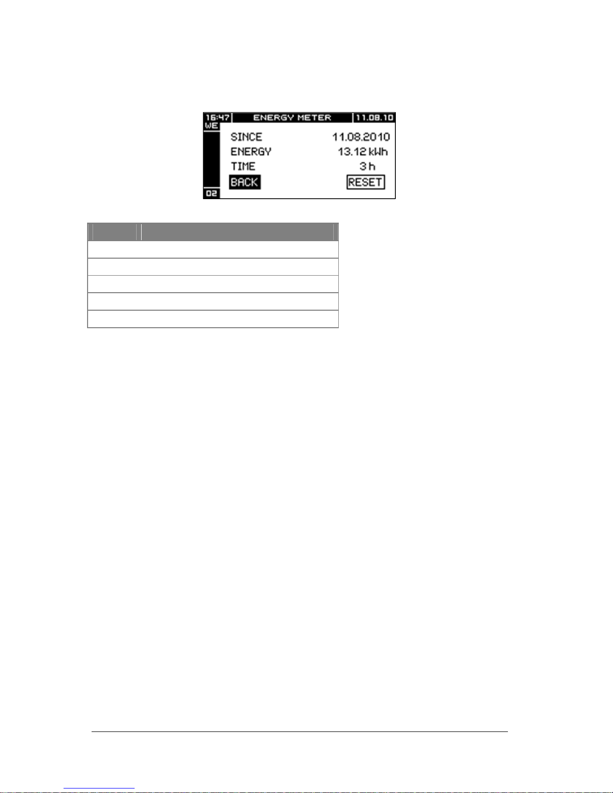
Energy Meter
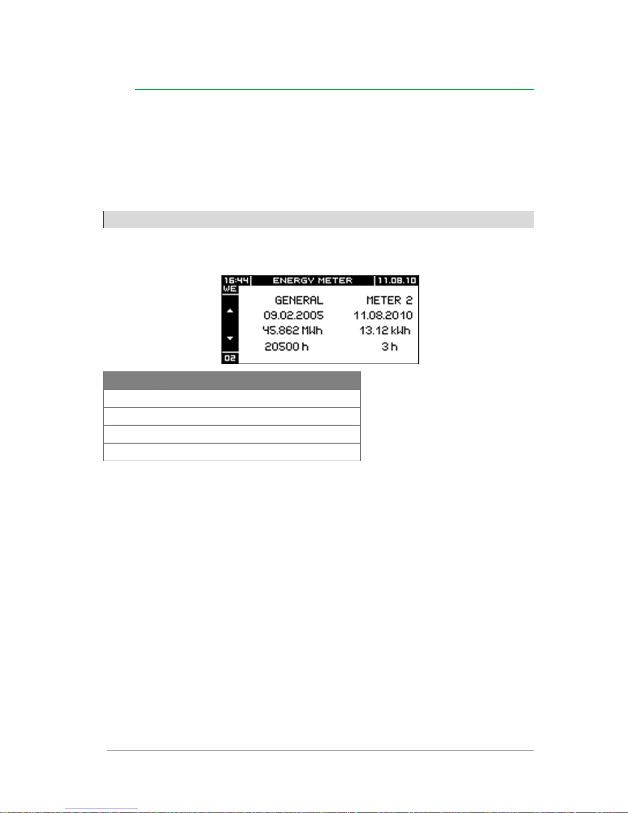
The energy meter enables the metering of energy and operating hours since the start of the
inverter or since a reset of the energy meter.
Key Function
BACK
Back to menu Settings
RESET
Set energy meter to 0
Select BACK or RESET
OK
Confirm selection
ESC
Back to menu Settings
Page 37
User’s Guide THEIA S String Inverters
357100.013, Issue 2.0, 2010 Aug
37
Information
The menu Information shows the following information:
— Operating data
— System data
— Inverter type
— Inverter version
— Event information
Note:
The menu Information merely displays the value. It is not possible to change the values.
Operating Data
Key Function
Call up screen Inverter version
Call up screen System data
ESC
Back to menu Main Menu
OK
Back to menu Main Menu
TOTAL
— Shows feed data of the inverter since the startup
— Resetting is not possible
METER 2
— Shows feed data of the inverter since the latest reset of meter 2
Page 38
38
User’s Guide THEIA S String Inverters
357100.013, Issue 2.0, 2010 Aug
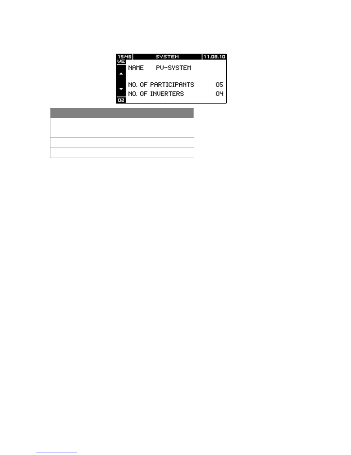
System data
NAME
— Shows the name of the PV system
NUMBER OF PARTICIPANTS
— Indicates the number of network participants (e. g. inverters and monitoring devices
such as PV-Monitor, ViewMaster and WebMaster).
NUMBER OF INVERTERS
— Shows the number of inverters in the network
Key Function
Call up screen Operating data
Call up screen Inverter type
ESC
Back to menu Main Menu
OK
Back to menu Main Menu
Page 39
User’s Guide THEIA S String Inverters
357100.013, Issue 2.0, 2010 Aug
39
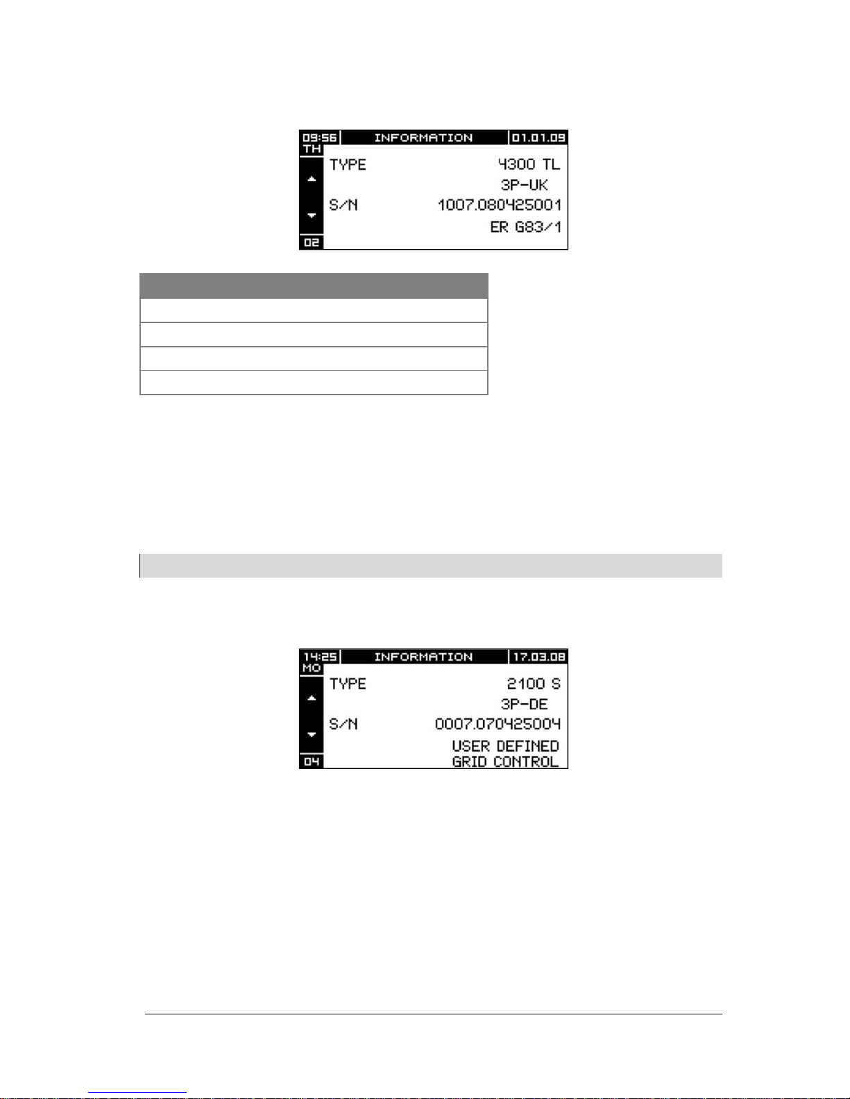
Inverter type
TYPE
— Indicates inverter type
S/N
— Indicates inverter serial number
Note:
When contacting the
Eltek Valere
service teams, have the part number and serial number ready.
After changing the inverter network parameters, the display shows USER-DEFINED
NETWORK MONITORING.
Key Function
Call up screen System data
Call up screen Inverter version
ESC
Back to menu Main Menu
OK
Back to menu Main Menu
Page 40
40
User’s Guide THEIA S String Inverters
357100.013, Issue 2.0, 2010 Aug
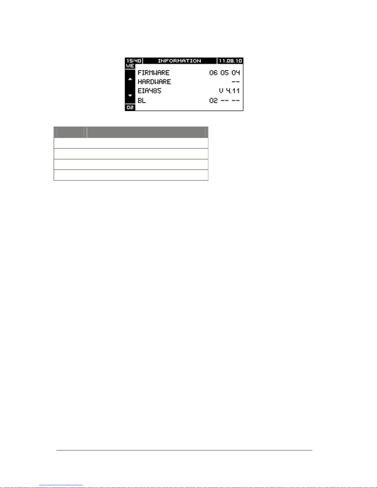
Inverter version
SOFTWARE
— Shows the inverter software version
HARDWARE
— Shows the inverter hardware version
EIA485
— Shows the data bus software version
Key Function
Call up screen Inverter type
Call up screen Operating data
ESC
Back to menu Main Menu
OK
Back to menu Main Menu
Page 41
User’s Guide THEIA S String Inverters
357100.013, Issue 2.0, 2010 Aug
41
Error Display
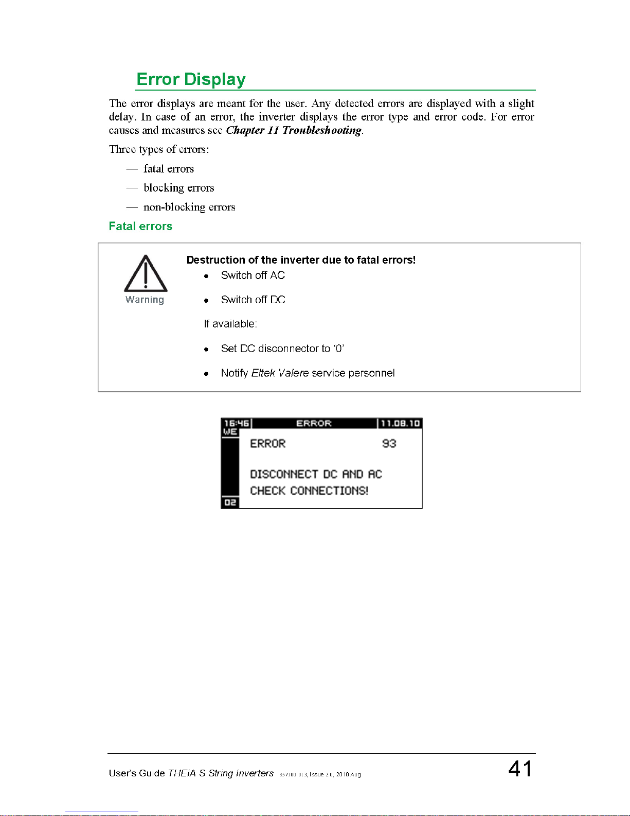
The error displays are meant for the user. Any detected errors are displayed with a slight
delay. In case of an error, the inverter displays the error type and error code. For error
causes and measures see Chapter 11 Troubleshooting.
Three types of errors:
— fatal errors
— blocking errors
— non-blocking errors
Fatal errors
Page 42
42
User’s Guide THEIA S String Inverters
357100.013, Issue 2.0, 2010 Aug
Blocking errors
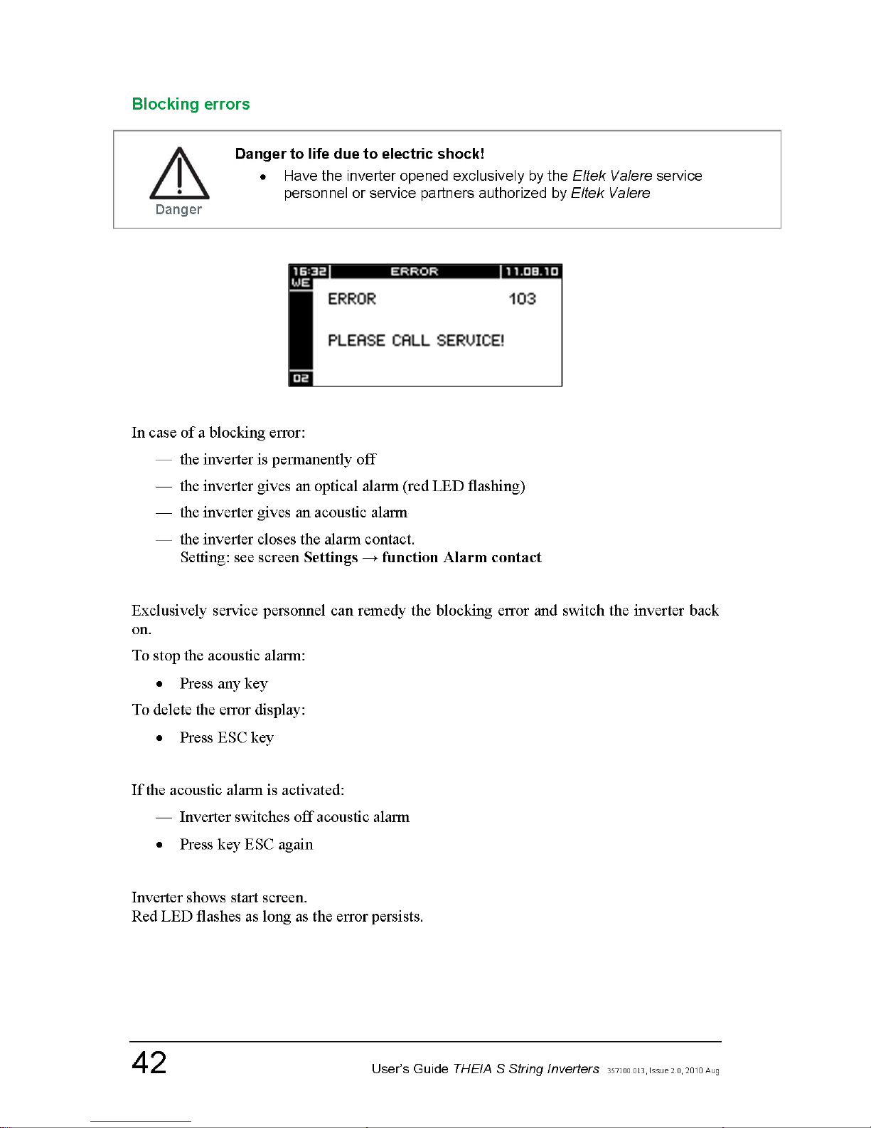
In case of a blocking error:
— the inverter is permanently off
— the inverter gives an optical alarm (red LED flashing)
— the inverter gives an acoustic alarm
— the inverter closes the alarm contact.
Setting: see screen Settings → function Alarm contact
Exclusively service personnel can remedy the blocking error and switch the inverter back
on.
To stop the acoustic alarm:
• Press any key
To delete the error display:
• Press ESC key
If the acoustic alarm is activated:
— Inverter switches off acoustic alarm
• Press key ESC again
Inverter shows start screen.
Red LED flashes as long as the error persists.
Page 43
User’s Guide THEIA S String Inverters
357100.013, Issue 2.0, 2010 Aug
43
Non-blocking errors and warnings
Key Function
OK
Clears the error display
ESC
Leave error display.
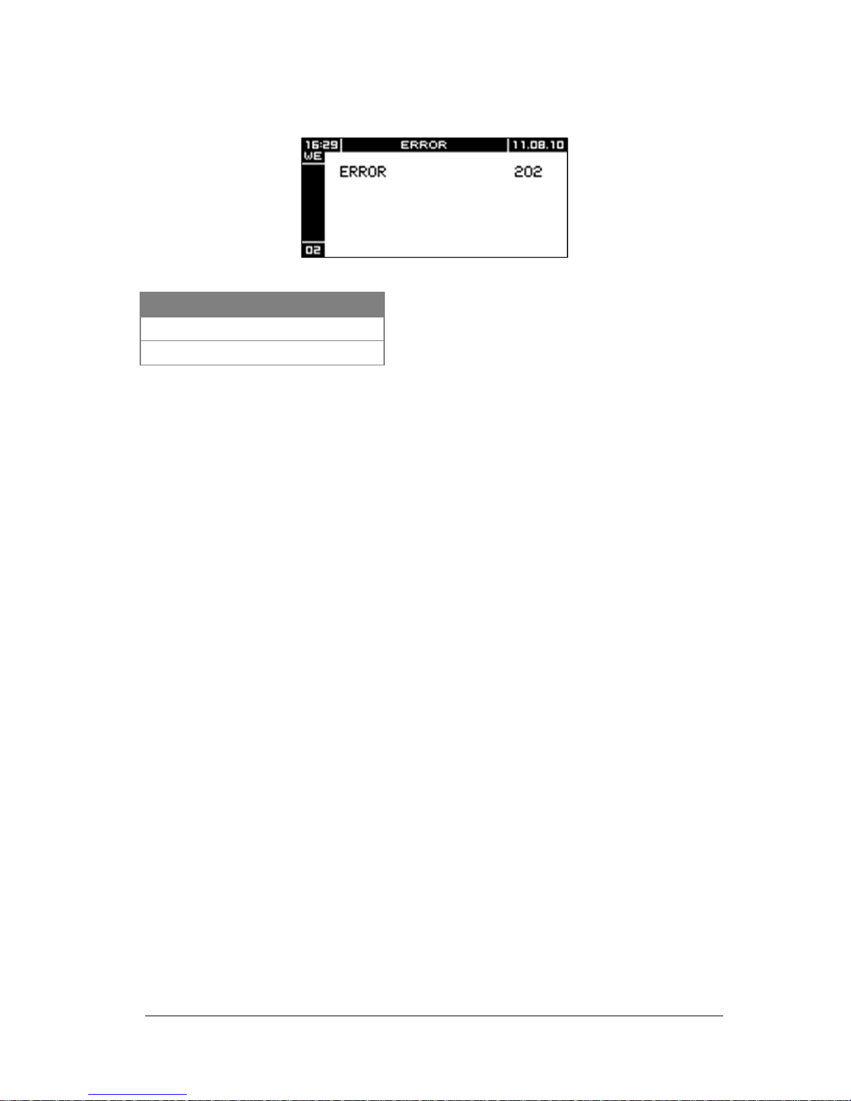
Non-blocking errors are of a transient nature (e.g. mains voltage surge). The inverter
remains switched off until the error cause no longer persists.
When the error has been remedied, the inverter automatically switches to normal operation.
Until the error is resolved:
— The inverter displays the screen Non-blocking error
— The red LED is flashing
• Delete error display with key ESC
Page 44
44
User’s Guide THEIA S String Inverters
357100.013, Issue 2.0, 2010 Aug
7. Service
Service Menu
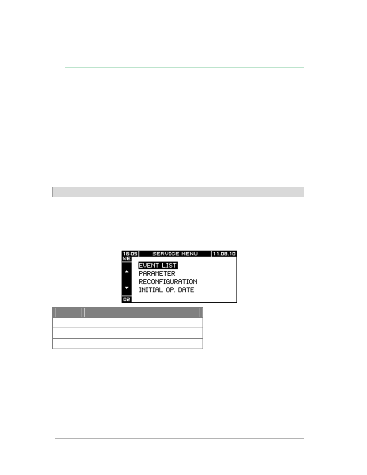
The menu Service offers the following information and functions:
— display event list
— display parameters
— activate/deactivate/configure insulation check
— reconfiguration
— display startup date
— display feed meter
Note:
To display other parameters or to change the parameters is only possible with a separate service tool.
To call up the Service Menu:
• Select item Date/Time in Settings menu and press keys and at once for about
3 sec
Key Function
Navigate within menu
ESC
Return to standard display
OK
Call up selected menu
Page 45
User’s Guide THEIA S String Inverters
357100.013, Issue 2.0, 2010 Aug
45
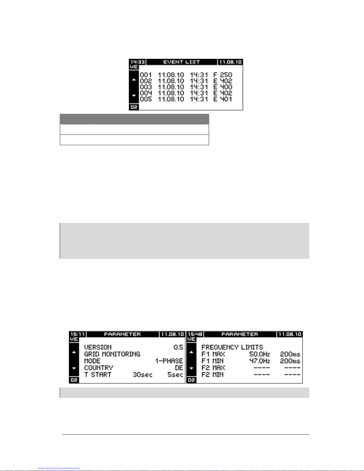
Event list
Key Function
Navigate within the event list
ESC
Return to menu Service
Columns:
— 1. column: Event no
— 2. column: Event date
— 3. column: Event time
— 4. column: Event code
Note:
The inverter shows the last 100 detected events.
Explanations about the events see
Chapter 12 Troubleshooting
.
Have the model part number, event code and the serial number ready when contacting the Eltek Valere service
personnel.
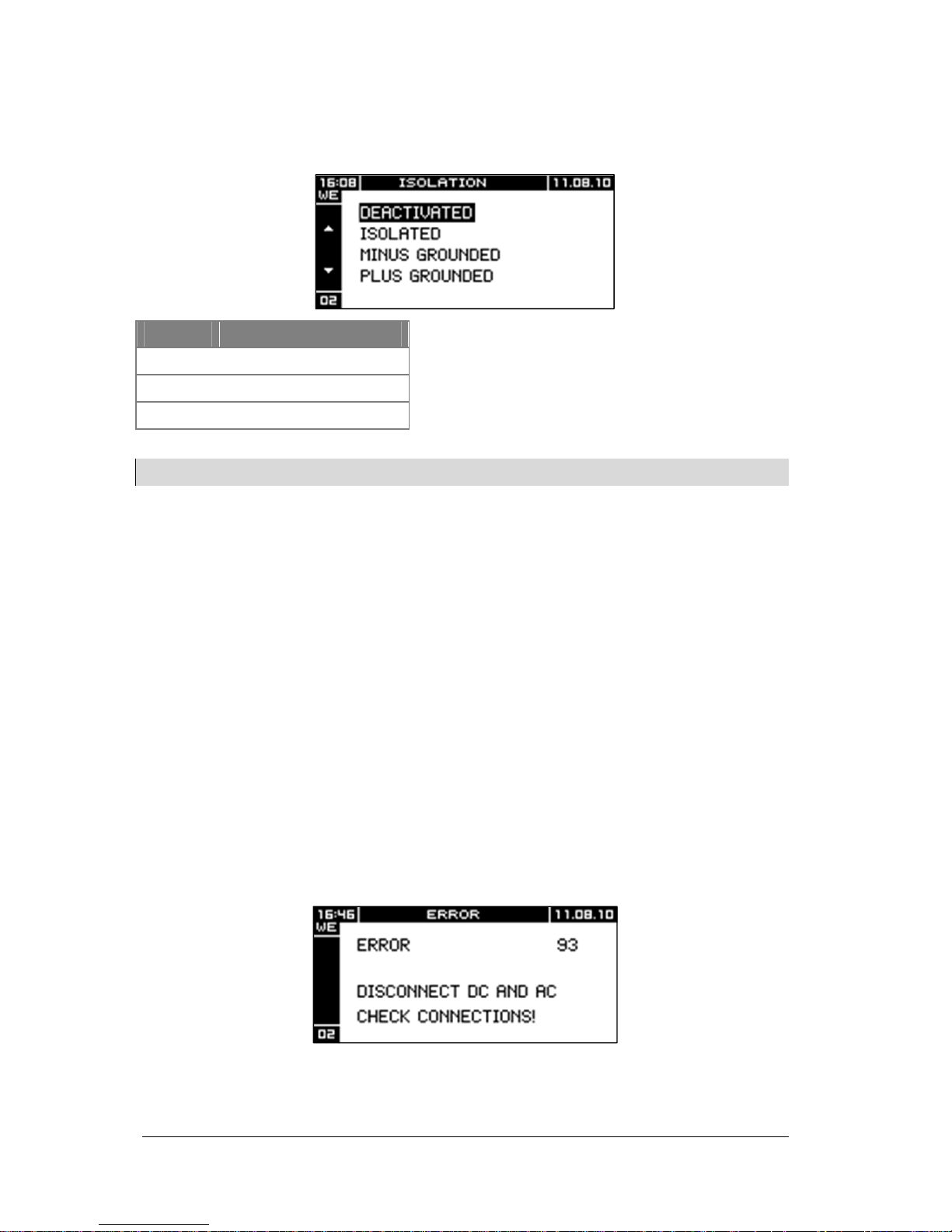
Parameters
In some supply areas, the values for supply voltage and frequency may differ temporarily
or permanently from the factory settings. It is possible to adapt the THEIA S inverter to
these values. Contact the Eltek Valere service personnel for more information.
The screens Parameters show the valid ENS type and the currently set parameters such as
start time, minimum and maximum values of frequency and voltage with the respective
reaction times.
Note:
The parameters can only be modified by certified persons with a separate
THEIA String
service tool.
Page 46
46
User’s Guide THEIA S String Inverters
357100.013, Issue 2.0, 2010 Aug
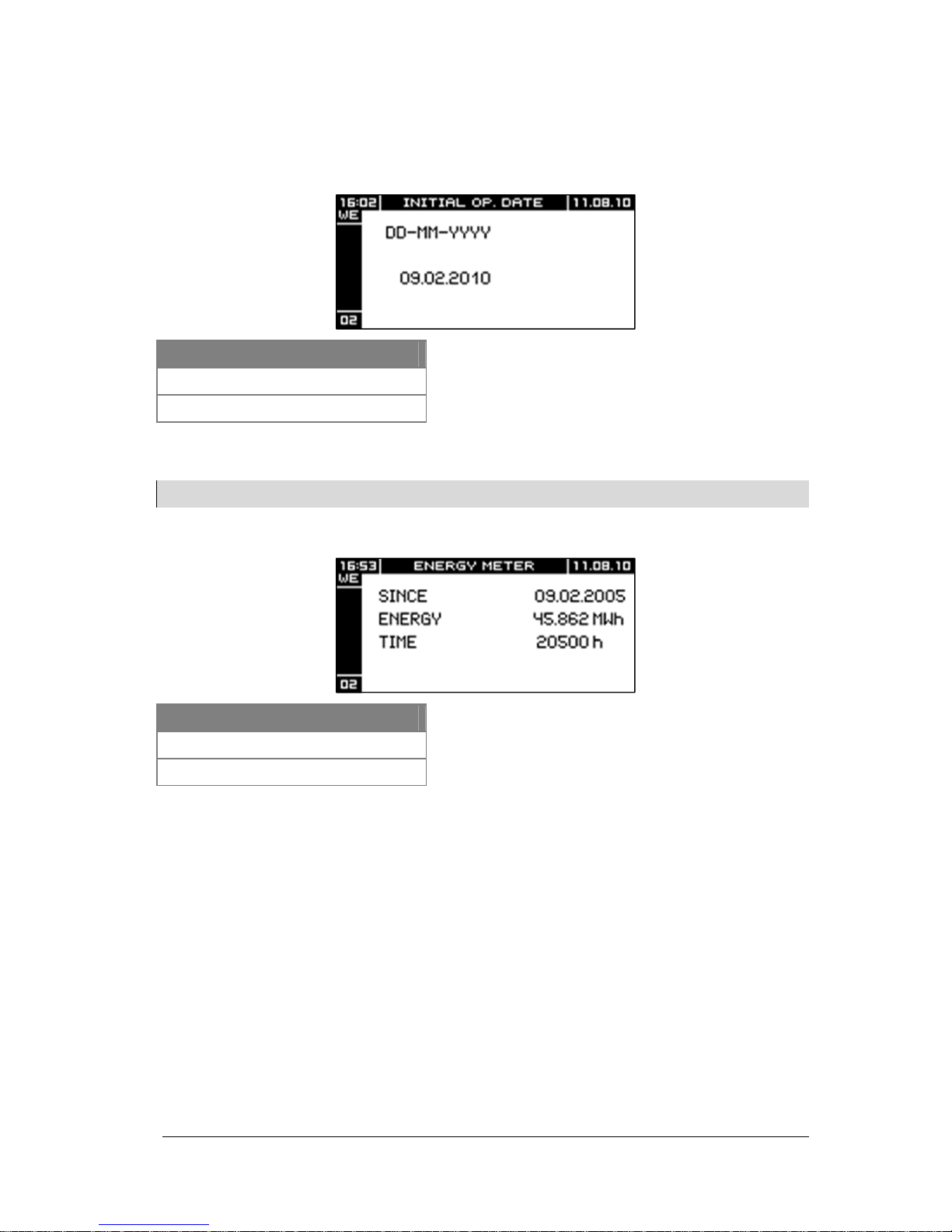
Isolation monitoring
The menu Insulation monitoring enables to check the insulation between solar generator
terminal and protective conductor.
Key Function
Navigate within menu
ESC
Back to Main Menu
OK
Accept selected mode
Note:
Insulation monitoring is deactivated in the factory.
When the OK key is pressed, the inverter accepts the changed parameters.
Four operating modes are possible depending on the type of installation:
— INSULATED
No connection installed between solar generator terminal and protective conductor
— MINUS GROUNDED
Negative terminal of the solar generator is connected to the protective conductor
— PLUS GROUNDED
Positive terminal of the solar generator is connected to the protective conductor
— DEACTIVATED
Activate insulation monitoring
If the insulation monitoring is activated, the inverter constantly performs the insulation
monitoring.
If the insulation resistance is too low:
— The inverter is separated from the mains until the error is resolved
— The inverter shows an error message
Page 47
User’s Guide THEIA S String Inverters
357100.013, Issue 2.0, 2010 Aug
47
Reconfiguration
Inverter shows screen Start initial startup (see Chapter 5, section Initial startup of a
single inverter)
Start Up
Key Function
OK
Return to menu Service
ESC
Return to menu Service
This displays the startup date.
Note:
This menu is read only. Values cannot be changed.
Meter
Key Function
OK
Return to menu Service
ESC
Return to menu Service
The menu is only a display Values cannot be changed
Inverter numbering
To change the inverter numbering after startup:
• Select Reconfiguration in the Service Menu
• Change inverter numbers see Chapter 5, section Initial startup of a single
inverter, subsection Inverter numbering.
Page 48
48 User’s Guide THEIA S String Inverters 357100.013, Issue 2.0, 2010 Aug
8. Maintenance
Maintenance
The inverter is maintenance-free.
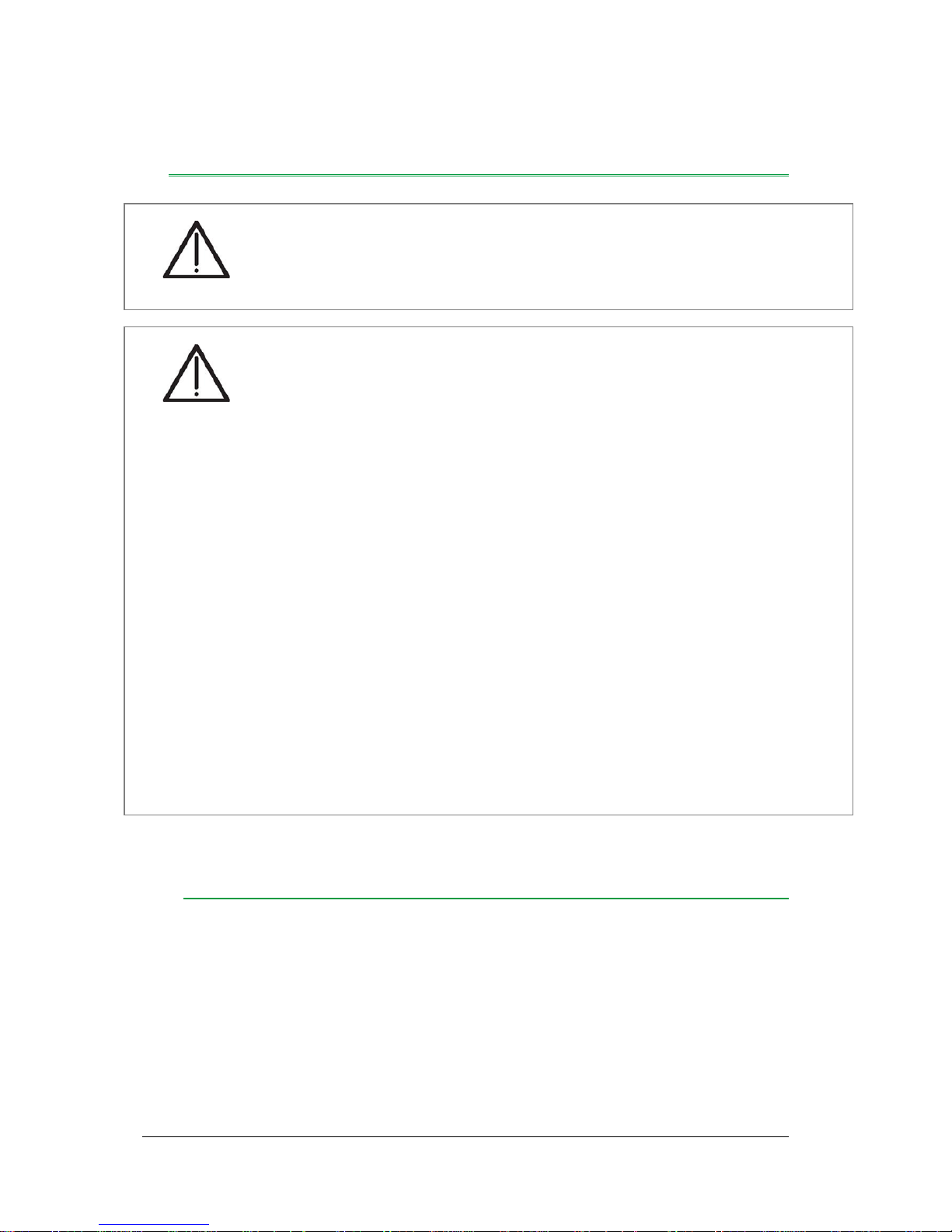
Danger to life due to electric shock!
• Have the inverter opened only by the Eltek Valere service personnel or
service partners authorized by Eltek Valere
Danger
Danger to life due to high DC and AC voltages!
• Wear insulating protective clothing and face protection
• Any cleaning or maintenance works must be carried out by qualified
specialistists only. The qualified specialist personnel require a license
from the relevant energy suppliers
Prior to every maintenance work or cleaning:
• Switch off the main power supply (fuse)
• Set switch knob of DC connector to ‘0’
• Do not touch terminals (DC/AC) for at least 5 minutes after disconnection
(discharging time of capacitors)
• Ensure that the DC cables are de-energized
In case of a THEIA S inverter without a DC disconnector:
• Pull the plugs in the following order:
1. AC side
2. DC side
Danger
Page 49
User’s Guide THEIA S String Inverters 357100.013, Issue 2.0, 2010 Aug 49
Cleaning
To assure the cooling, regularly:
• Clean ventilation openings with:
— vacuum cleaner
— soft brush
— compressed air
Damage of fan due to high fan speed!
• The THEIA S inverter must be cleaned carefully with compressed air.
Caution
Page 50
50
User’s Guide THEIA S String Inverters
357100.013, Issue 2.0, 2010 Aug
9. Placing Out of Operation
Dismounting
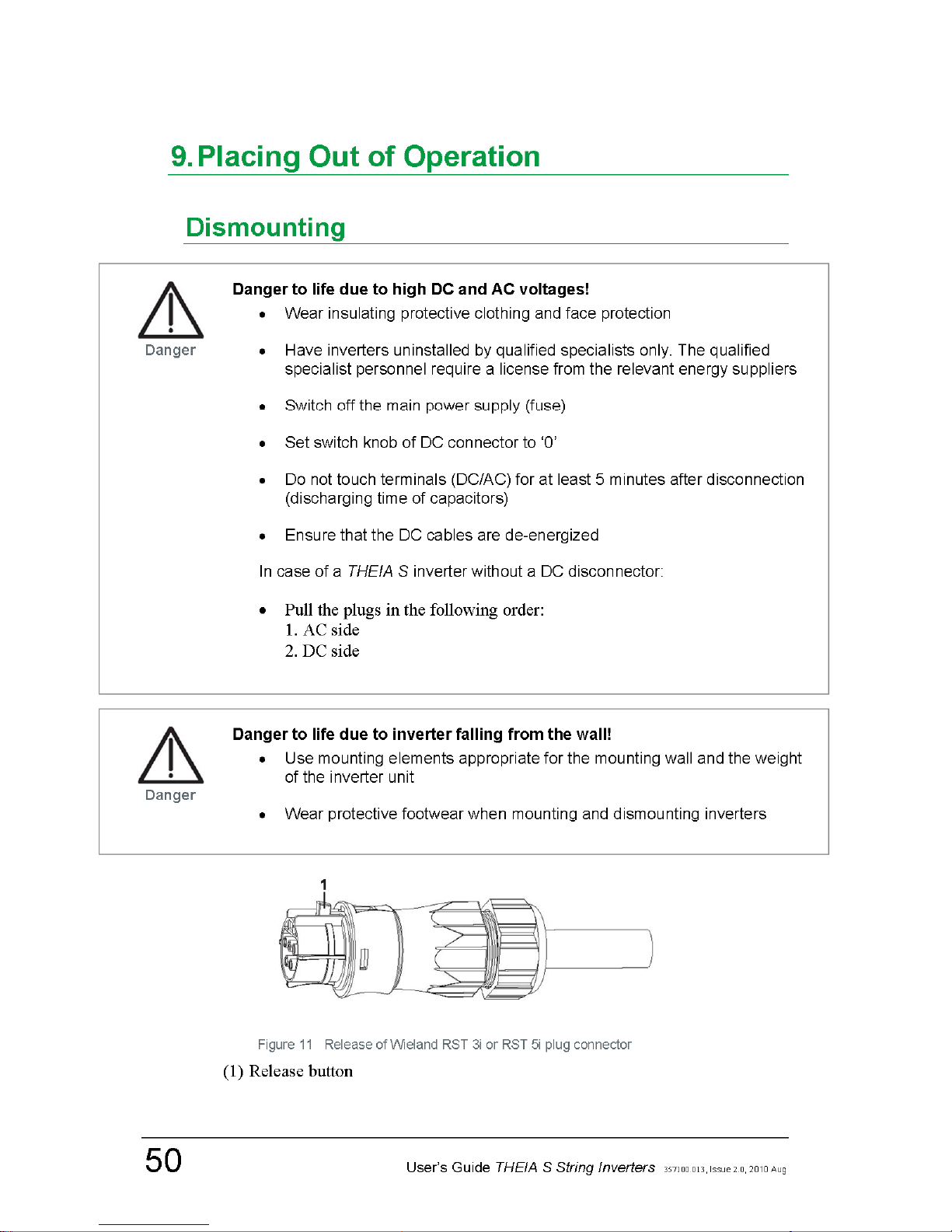
Figure 11 Release of Wieland RST 3i or RST 5i plug connector
(1) Release button
Page 51

User’s Guide THEIA S String Inverters 357100.013, Issue 2.0, 2010 Aug 51
To disconnect the inverter:
• Switch off the main power supply (fuse)
• Unlock and pull the feed output plug (AC-side)
• Pull plug connector of output voltage (DC side) or set DC disconnector to ‘0’
• Disconnect remaining connectors as required
Dismount the inverter as follows:
• Loosen and remove the locking screws (paper strip)
• Lift the inverter up and out of the mounting fixture
Remove the mounting fixture as follows:
• Unscrew the mounting fixture
• Insert the mounting fixture at the back of the inverter
• Secure the mounting fixture with the locking screws
Return Consignment
In case of a return consignment:
• Pack the inverter in the packaging of the replacement.
If a single inverter is returned:
• Re-use the original packaging, or pack securely with alternative packaging.
Page 52
52
User’s Guide THEIA S String Inverters
357100.013, Issue 2.0, 2010 Aug
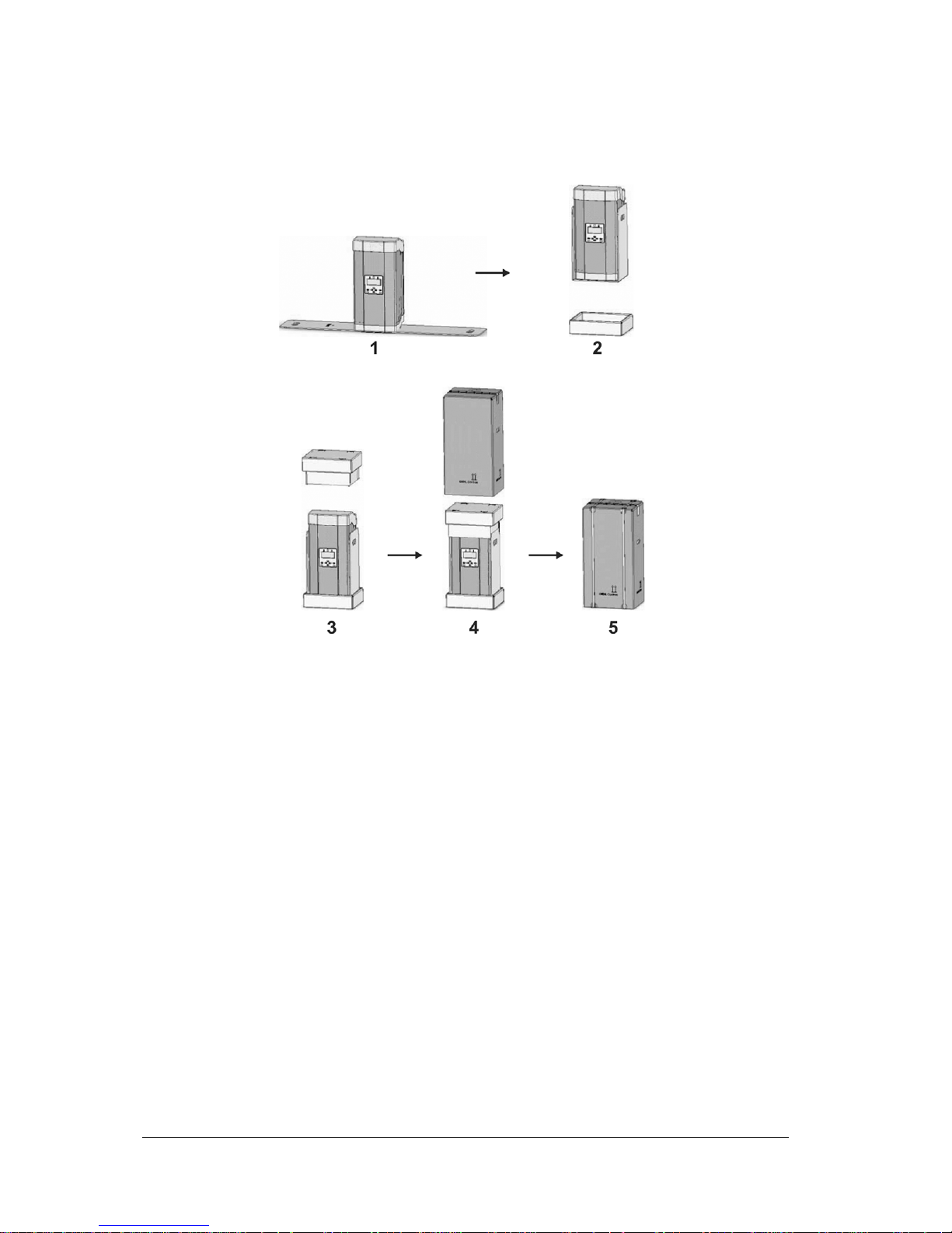
Packaging
When using the original packaging, pack the inverter as follows:
1. Rest the inverter on the inner packaging
2. Put the inverter with the inner packaging into the base pad
3. Place the lid pad on the inverter
4. Slide the outer box over the inverter
5. Secure the box with packing straps
Page 53
User’s Guide THEIA S String Inverters
357100.013, Issue 2.0, 2010 Aug
53
10. Disposal
• Dispose of packaging and consumed parts according to the rules and
regulations applicable in the country where the device was installed
• Do not dispose of the THEIA S inverter in household waste
Note:
Eltek Valere
takes back
THEIA S
inverters.
It is possible to dispose of
THEIA S
inverters through communal disposal of electrical appliances.
Page 54
54 User’s Guide THEIA S String Inverters 357100.013, Issue 2.0, 2010 Aug
11. Troubleshooting
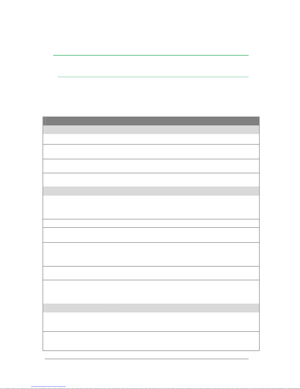
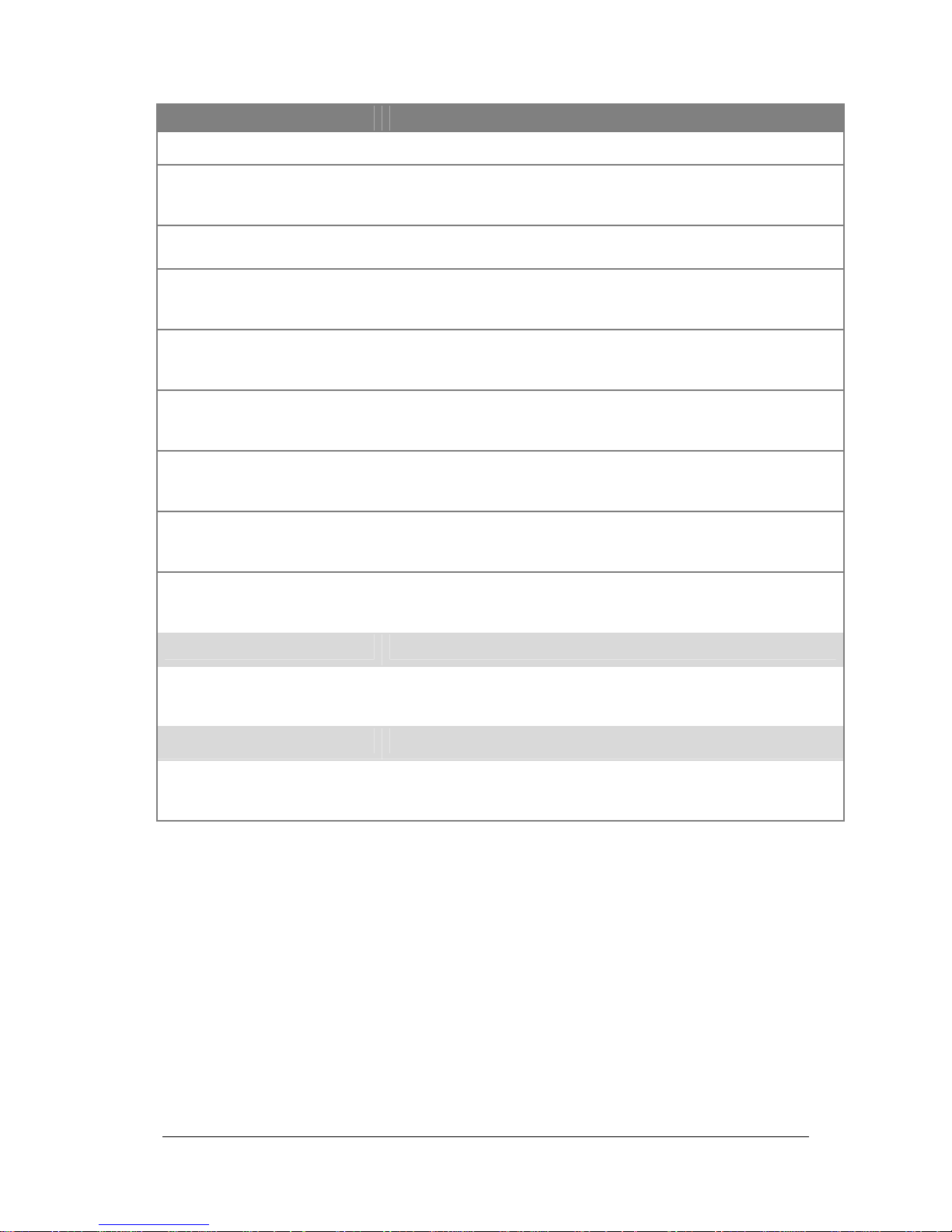
Table of events
To isolate the error, have the following information ready when calling the service:
— displayed error number (No)
— serial number of the inverter (see Chapter 6, section Information)
No Operating status Measure
Blocking errors
90
AC voltage too high Separate inverter from mains. Check connection of AC plug.
91
DC voltage too high Separate inverter from mains. Separate inverter from DC terminal.
Check module interconnection.
92
Polarity of DC connection
reversed
Check DC connection.
93
Insulation error between
PV+ or PV- and earth
Check insulation of PV modules. Check insulation of PV wiring.
Blocking errors
100
to
103
Blocking system error Separate inverter from mains. Restart inverter. If measure is not
successful call service personnel.
104
DC voltage too high Check module interconnection.
105
Startup: Polarity of DC
connection reversed
Check DC connection.
106
to
129
Blocking system error Separate inverter from mains. Restart inverter. If measure is not
successful call service personnel.
130
Connections L and N
reversed
Check L and N connections on AC plug
131
to
199
System error Separate inverter from mains. Restart inverter. If measure is not
successful call service personnel.
Non-blocking errors
201
Amplitude limit for feed
phase exceeded or fallen
below
Have voltage amplitude of feed phase checked.
202
to
204
Exclusively for 3 phase
ENS. Amplitude limit of
phase voltages exceeded
Ensure that all fuses are switched on. Startup:- have inverter 3phases connected.
Page 55
User’s Guide THEIA S String Inverters 357100.013, Issue 2.0, 2010 Aug 55
No Operating status Measure
or fallen below
208
System incident on feed
phase (voltage peak)
If error occurs frequently, have all bondings and fuses between the
consumer’s terminal and the inverter checked. Have the mains
quality checked.
210
211
Mains frequency limit
exceeded or fallen below
If inverter is running on emergency power (different mains
frequency), then no action required
212
to
219
Diagnosis support during
service
Provide the service personnel with the error code if required
220
to
224
Measured temperatures
too high
Check ventilation openings
230
to
233
Temperature sensor
defective
Separate inverter from mains. Restart inverter. If measure is not
successful call service personnel.
234
to
289
Diagnosis support during
service
Provide the service personnel with the error code if required
290
Subsequent error in case
of system incident or
excess temperature
No action required
291
to
299
Diagnosis support during
service
Provide the service personnel with the error code if required
Warning
300
to
399
Diagnosis support during
service Inverter stores
warning in event memory
Provide the service personnel with the error code if required
Information
400
to
499
Diagnosis support during
service Inverter stores
warning in event memory
Provide the service personnel with the error code if required
Page 56

56 User’s Guide THEIA S String Inverters 357100.013, Issue 2.0, 2010 Aug
12. Standards and Approvals
The inverter complies with the following standards:
• DIN EN 50178
• DIN EN 61000-6-2
• DIN EN 61000-6-3
• DIN VDE 0126-1-1
• DIN EN 61000-3-2
• DIN EN 61000-3-3
• DIN EN 61000-3-11
• DIN EN 61000-3-12
Page 57
User’s Guide THEIA S String Inverters 357100.013, Issue 2.0, 2010 Aug 57
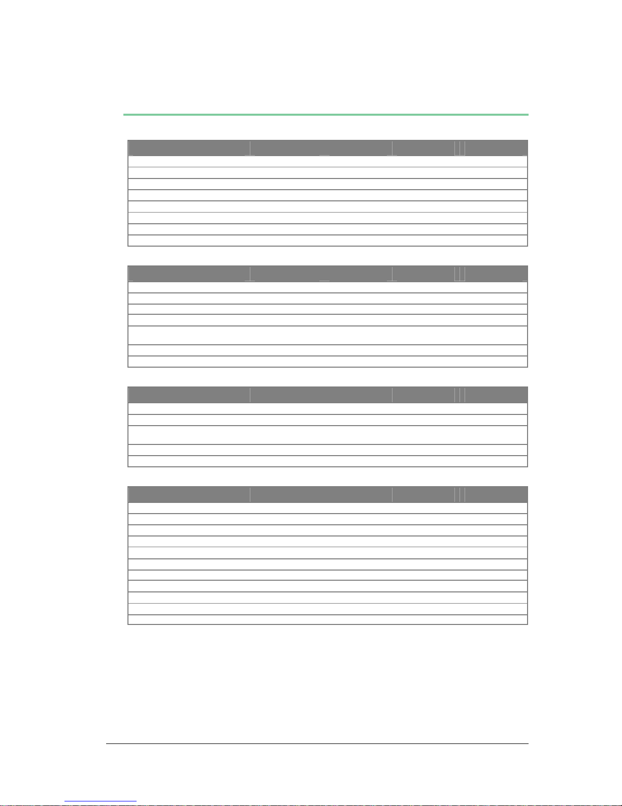
13. Technical Data
Input characteristics 2100 S 2800 S 3100 S 3800 S
Max PV power 2,300 Wp 3,200 Wp 3,450 Wp 4,200 Wp
Max DC power 2,100 W 2,800 W 3,100 W 3,800 W
Max DC voltage 480 V 780 V 780 V 780 V
PV voltage range, MPPT 206 V — 390 V 313 V — 630 V 314 V — 630 V 315 V — 630 V
Max input current 9.0 A 9.0 A 9.0 A 12.0 A
Number of string inputs 1 1 1 2
DC section switch device optional DC disconnector, integrated in the appliance
Reverse battery protection Yes
Output characteristics 2100 S 2800 S 3100 S 3800 S
Max AC power 1,900 W 2,600 W 2,800 W 3,600 W
Nominal AC-power rating 1,750 W 2,400 W 2,550 W 3,300 W
Max AC 8.3 A 11.3 A 12.2 A 15.7 A
Feed operation starts at 13 W 14 W 14 W 18 W
Mains voltage /
mains frequency range
230 V (-/+20%) / 47.5 Hz — 52.5 Hz
Short-circuit proof Yes
Internal consumption at night below 2.5 W
Interfaces 2100 S 2800 S 3100 S 3800 S
DC input Multicontact MC3, MC4
AC output Wieland RST 3i/5i
Inverter network EIA485, 2xRJ45 Western Modular, additional Plug connector with terminal
screws
PC connection (service) EIA232, SubD 9-pole socket
Potential-free contact max 24 V AC/2A, plug connectors with terminal screws
Appliance data 2100 S 2800 S 3100 S 3800 S
Max conversion efficiency 94.7% 95.3% 95.3% 95.6%
European efficiency 93.7% 94.4% 94.4% 94.6%
Working temperature range -20 °C — 60 °C
Max temp. for nominal load 45 °C
Max storage temperature 80 °C
Protection Rating IP 54 according to DIN EN 60529
Dimensions H 720 mm x W 320 mm x D 250 mm
Weight 30 kg 35 kg 35 kg 42 kg
Circuit concept LF transformer with galvanic separation
Optical display Full graphic LCD 170x76 pixels
Integrated datalogger 4 MB, sufficient for 30 yrs operating time
Page 58
58 User’s Guide THEIA S String Inverters 357100.013, Issue 2.0, 2010 Aug
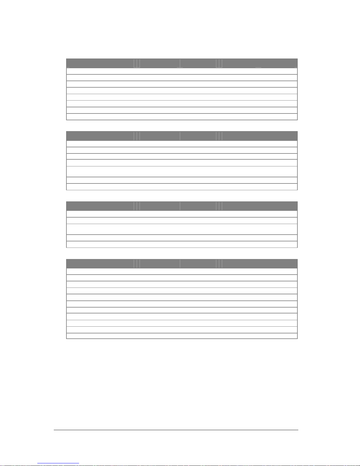
Input characteristics 4300 S 4301 S 4600 S 4601 S
Max PV power 4,800 Wp 4,800 Wp 5,100 Wp 5,100 Wp
Max DC power 4,300 W 4,300 W 4,600 W 4,600 W
Max DC voltage 780 V 580 V 780 V 580 V
PV voltage range, MPPT 320 V — 630 V 277 V — 470 V 320 V — 630 V 278 V — 470 V
Max input current 12.5 A 15.0 A 13.0 A 16.0 A
Number of string inputs 2 2 2 2
DC section switch device optional DC disconnector, integrated in the appliance
Reverse battery protection Yes
Output characteristics 4300 S 4301 S 4600 S 4601 S
Max AC power 4,050 W 4,050 W 4,200 W 4,200 W
Nominal AC-power rating 3,680 W 3,680 W 3,800 W 3,800 W
Max AC 17.6 A 17.6 A 18.3 A 18.3 A
Feed operation starts at 18 W 17 W 18 W 17 W
Mains voltage /
mains frequency range
230 V (-/+20%) / 47.5 Hz — 52.5 Hz
Short-circuit proof Yes
Internal consumption at night below 2.5 W
Interfaces 4300 S 4301 S 4600 S 4601 S
DC input Multicontact MC4
AC output Wieland RST 3i/5i
Inverter network EIA485, 2xRJ45 Western Modular, additional Plug connector with terminal
screws
PC connection (service) EIA232, SubD 9-pole socket
Potential-free contact max 24 V AC/2A, plug connectors with terminal screws
Appliance data 4300 S 4301 S 4600 S 4601S
Max conversion efficiency 95.6% 94.6% 95.6% 94.6%
European efficiency 94.7% 93.5% 94.8% 93.6%
Working temperature range -20 °C — 60 °C
Max temp. for nominal load 45 °C
Max storage temperature 80 °C
Protection Rating IP 54 according to DIN EN 60529
Dimensions H 720 mm x W 320 mm x D 250 mm
Weight 42 kg 43 kg 42 kg 43 kg
Circuit concept LF transformer with galvanic separation
Optical display Full graphic LCD 170x76 pixels
Integrated datalogger 4 MB, sufficient for 30 yrs operating time
Page 59

User’s Guide THEIA S String Inverters 357100.013, Issue 2.0, 2010 Aug 59
14. EU Declaration of Conformity
Name and address of the issuer
Eltek Valere
Gråterudv. 8, Pb 2340 Strømsø
3003 Drammen, Norway
Product designation
Solar inverter
Type designation
THEIA 2100S, 2800S, 3100S, 3800S, 4300S, 4301S, 4600S, 4601S
The designated devices comply with the provisions of EU directives
Especially the Low Voltage Directive 2006/65/EG and the EMC Directive 2004/108/EG
The designated devices conform to the following norms:
— DIN EN 50178: 1998-04
— VDE 0126-1-1: 2006-02
— ER G83/1
— DIN EN 61000-3-2: 2000 / A: 2004
— DIN EN 61000-3-12: 2005-09
— DIN EN 61000-3-3: 1994 / A2: 2005
— DIN EN 61000-3-11: 2001-04
— DIN EN 61000-6-2: 2006-03
— DIN EN 61000-6-3: 2007-09
Consequently the products mentioned above carry the CE mark
Furthermore, we declare that the products mentioned above comply with the prescriptions
of the VDEW (German Electricity Industry Association) that apply to solar inverters
according to the “Directive for the Connection and Parallel Operation of Energy
Generation Equipments in the Low-Voltage Mains”.
Page 60

60 User’s Guide THEIA S String Inverters 357100.013, Issue 2.0, 2010 Aug
15. Warranty for
THEIA S
(Address: Eltek Valere AS, HQ: Gråterudveien 8, 3036 Drammen, Norway. Postal
address: P.O. Box 2340 Strømsø, 3003 Drammen, Norway )
1. Warranted Products
This manufacturer warranty is valid for the types THEIA S and TL range of string inverters
for photovoltaic systems supplied by Eltek Valere, as long as there is proof that the new
appliance was purchased from Eltek Valere or a wholesale or specialist dealer or a
specialized installation firm authorized by Eltek Valere (products entitled to warranty).
Such evidence is regarded as given when Eltek Valere is provided with an original invoice
documenting the delivery of a Warranted Product to the Warranted User and if Eltek
Valere is identified by an authentic label on the Warranted Product
2. Beneficiaries from this manufacturer’s warranty
Eltek Valere grants this warranty only to users who demonstrably have purchased, and are
the actual users of a Warranted Product (Warranted User) Traders of any kind and trade
level do not gain from this warranty any rights and claims against Eltek Valere
3. Establishment of the warranty
The warranty is meant as an offer by Eltek Valere directly to the Warranted User on
entering a warranty agreement under the conditions laid down in this document. The
warranty contract is established directly and automatically between Eltek Valere and the
Warranted User at the moment of purchase of a Warranted Product, if the Warranted User
does not object to the establishment of the warranty agreement, in writing to Eltek Valere
within 2 (two) weeks from the purchase date of a Warranted Product
4. Coverage of the manufacturer’s warranty
The warranty grants the Warranted User warranty rights in addition to the Warranted
User’s warranty rights granted by the respective vendor Warranty rights vis-à-vis the
respective vendor and statutory product liability rights are unaffected by this warranty
5. Period and assertion of the manufacturer’s warranty
The warranty applies to defects of the Warranted Products which demonstrably occur
between the beginning of the first and the end of the sixtieth month after installation and
commissioning of a Warranted Product at the Warranted User’s premises (Warranty
Period). This Warranty Period ends not later than 72 months after the manufacturing date
of the Warranted Product, as stated on the type plate of the Warranted Product. For
Warranted Products repaired or replaced by Eltek Valere, the warranty expires with the end
of the original Warranty Period. Legal and/or contractual warranty claims of any kind,
which arise during a statutory or contractual warranty period, cannot be derived from this
warranty.
Any claims based on the warranty must be asserted in writing by the Warranted User to
Eltek Valere within the Warranty Period. Such warranty claims can be submitted through
an authorized specialist retailer, wholesaler or specialist installation company.
Page 61

User’s Guide THEIA S String Inverters 357100.013, Issue 2.0, 2010 Aug 61
6. Rights under the supplier’s warranty – damage and costs not covered
If a defect of the Warranted Product occurs during the Warranty Period and if Eltek Valere
is responsible for this defect and if this defect impairs or reduces the functionality of the
Warranted Product to a significant extent, Eltek Valere will choose to carry out either freeof-charge repairs or free-of-charge replacement of the Warranted Products with a product
that offers at least the same or the same type of functionality and performance.
Such repairs or replacement will be carried out only at the Eltek Valere factory Transport
to Eltek Valere must be in the original packaging or other packaging that is at least of the
same quality as the original packaging. If the Warranted user requests repair or
replacement at a site other than the Eltek Valere factory, Eltek Valere can agree to this
request. In this case, however, the Warranted User will bear any travel costs and additional
labor costs according to Eltek Valere standard rates.
Any claims from the warranty beyond free-of-charge repair or free-of-charge replacement
are ruled out, especially any claims on compensation for defect-related capital damage, eg.
loss of profit including compensation for lost power feeds, costs of installation and
dismantling, costs of fault diagnostics, recall costs and interruption to production
processes.
If no defect is found in the Warranted Product sent in for repair or replacement, or if there
is no claim based on the warranty for any other reason, Eltek Valere may demand from the
Warranted User an administration fee (flat rate per product) plus the costs of transport back
to the Warranted User.
Any claims based on this warranty expire 6 months after occurrence of the fault, but not
later than 3 months after the end of the Warranty Period.
7. Exclusion cases
Any claims of the Warranted User are excluded in the following cases:
Improper use
Unprofessional or incorrect installation, installation not complying to standards,
or installation not following the installation directions or instructions provided
by Eltek Valere
Unprofessional or incorrect operation and use, or operation and use against the
operating directions or instructions provided by Eltek Valere
Operation with defective protective systems
Any unauthorized modifications or repairs
Use of replacement parts and accessories non-compliant with the original Eltek
Valere specifications
Failure to perform continuous maintenance according to the maintenance
directions and instructions provided by Eltek Valere
Removal, damage or destruction of the sealing or the type plate installed by
Eltek Valere
Foreign-body influence and force majeure
Non-compliance with applicable safety regulations
Transport damage
Page 62

62 User’s Guide THEIA S String Inverters 357100.013, Issue 2.0, 2010 Aug
Lightning damage
8. Portability of the guarantee
This agreement on guarantee and the rights that result from it can only be transferred from
a licensee to a third party with a previous, written approval. When the guaranteed products
are removed from the original assembly and operation spot and reassembled at a different
location the guarantee expires automatically
In cases other than those agreed on the guarantee may be transferred to a third licensee
when (i) the third licensee acquires the operation real estate from the licensee entitled to
the guarantee, (ii) proof of the acquisition is presented to Eltek Valere in written and with
the naming of the third licensee, (iii) the products assembled that are guaranteed remain
unchanged and (iv) the third licensee declares to Eltek Valere its agreement to these
conditions of guarantee in written form
9. General provisions
Claims by the Warranted User based on this warranty can only be transferred to third
parties with prior written consent of Eltek Valere
Should any clause of this warranty be or become void, all other stipulations of the warranty
remain in force. In place of the clause that is or has become void, a valid clause is
automatically regarded as agreed. The replacement clause will be as close as possible to
the voided clause in its economic substance. The same rule applies to any missing clause
in this agreement
This warranty is subject only to the laws of the Kingdom of Norway, excluding the
stipulations of Private International Law and the UN Convention on the International Sale
of Goods
The exclusive place of jurisdiction in case of any conflict arising from, or in connection
with this warranty, is Oslo, Norway.
Page 63

User’s Guide THEIA S Inverters 357100.013, Issue 2.0, 2010 Aug 63
Page 64
www.eltekvalere.com
Headquarters:
Eltek Valere
Gråterudv. 8, Pb 2340 Strømsø, 3003 Drammen, Norway
Phone: +47 32 20 32 00 Fax: +47 32 20 32 10
 Loading...