

Wireless ADSL2+ Router User’s Guide
Wireless
ADSL2+ Router
User’s Manual
1

Wireless ADSL2+ Router User’s Guide
Table of Contents
1 Introduction .......................................................... 8
Features ................................................................................ 8
Device Requirements ........................................................... 8
Using this Document ............................................................. 9
Notational conventions .................................................. 9
Typographical conventions ............................................ 9
Special messages .......................................................... 9
Getting Support ..................................................................... 9
2 Getting to know the device ................................ 10
Computer / System requirements ...................................... 10
Package Contents .............................................................. 10
For Annex-B 802.11n WLAN ADSL2+
Router ....................................................................... 10
For Annex-A 802.11n WLAN ADSL2+
Router ....................................................................... 10
Installation & Setup ............................................................. 11
LED meanings & activations .............................................. 13
Back Panel Connectors ............................................... 14
3 Computer configurations under
different OS, to obtain IP address
automatically ................................................... 16
4 Utility CD execution ........................................... 29
Connecting the Hardware ................................................... 29
Wireless Connection ........................................................... 35
5 USB 3G Configuration (This function
may vary depending on model) ...................... 37
Connecting the Hardware ................................................... 37
USB 3G Configuration ........................................................ 38
6 Getting Started with the Web pages ................. 45
Accessing the Web pages .................................................. 45
Testing your Setup .............................................................. 48
Default device settings ........................................................ 48
7 Overview ........................................................... 51
Internet access settings ...................................................... 53
About Wireless ADSL2+ Router ......................................... 53
8 Status ................................................................ 54
Device Info .......................................................................... 54
ADSL ................................................................................... 56
2

Wireless ADSL2+ Router User’s Guide
Statistics .............................................................................. 57
9 Internet Access .................................................. 58
Types of Internet Access .................................................... 59
Configuring your PPPoE DSL connection ......................... 60
Configuring your PPPoA DSL connection ......................... 62
Configuring your Bridged DSL connection ......................... 64
Configuring your 1483 MER by DHCP .............................. 65
Configuring your 1483 MER by Fixed IP ........................... 66
3G Settings.......................................................................... 68
ATM Settings ....................................................................... 70
ADSL Settings ..................................................................... 72
10 Local Network Configuration ............................. 75
Changing the LAN IP address and subnet
mask ................................................................................ 75
Adding the Secondary LAN IP address and
subnet mask .................................................................... 80
11 DHCP Settings .................................................. 81
DHCP Server Configuration ............................................... 81
DHCP Relay Configuration ................................................. 83
DHCP None Configuration ................................................. 85
12 DHCP Static Configuration ................................ 86
DHCP Static Configuration ................................................. 86
13 LAN IPv6 Configuration ..................................... 87
DHCP Static Configuration ................................................. 87
14 Wireless Network .............................................. 88
Basic Settings ..................................................................... 88
Security ................................................................................ 90
WEP + Encryption Key ................................................ 92
WEP + Use 802.1x Authentication .............................. 93
WPA/WPA2/WPA2 Mixed + Personal
(Pre-Shared Key)...................................................... 93
WPA/WPA2/WPA2 Mixed + Enterprise
(RADIUS) .................................................................. 95
Wireless Multiple BSSID Settings ...................................... 96
Access Control .................................................................... 97
Allow Listed .................................................................. 98
Deny Listed .................................................................. 99
Advanced Settings ............................................................ 100
WPS .................................................................................. 103
Introduction of WPS ................................................... 103
3

Wireless ADSL2+ Router User’s Guide
Supported WPS features ........................................... 103
AP mode ..................................................................... 104
AP as Enrollee ........................................................... 104
AP as Registrar .......................................................... 104
AP as Proxy ............................................................... 104
Infrastructure-Client mode ......................................... 104
Instructions of AP’s and Client’s
operations ............................................................... 105
Operations of AP - AP being an enrollee ......................... 107
Operations of AP - AP being a registrar ........................... 118
AP mode ..................................................................... 118
Push Button method .................................................. 122
15 Routing ............................................................126
Static Route ....................................................................... 126
IPv6 Static Route .............................................................. 128
RIP ..................................................................................... 129
16 DMZ .................................................................131
Configuring DMZ ............................................................... 131
17 Virtual Server ...................................................133
Configuring Virtual Server ................................................. 133
Configuring custom applications ...................................... 134
Virtual Server for FTP ................................................ 135
Port Forwarding for HTTP ......................................... 138
Deleting custom applications ..................................... 141
18 ALG .................................................................142
Configuring ALG ............................................................... 142
19 NAT Exclude IP ...............................................143
Configuring NAT Exclude IP ............................................. 143
20 Port Trigger .....................................................144
Configuring Port Trigger ................................................... 144
21 FTP ALG Portl .................................................145
Configuring Port Trigger ................................................... 145
22 Nat IP Mapping................................................146
Configuring Port Trigger ................................................... 146
23 IP QoS .............................................................147
IP QoS ............................................................................... 147
24 CWMP Config .................................................149
CWMP Configuration ........................................................ 149
25 Port Mapping ...................................................151
4

Wireless ADSL2+ Router User’s Guide
Port Mapping ..................................................................... 151
26 Bridging ...........................................................154
Bridging ............................................................................. 154
27 Client Limit .......................................................155
Client Limit ......................................................................... 155
28 Tunnel Configuration .......................................156
Tunnel Configuration ........................................................ 156
29 Others ..............................................................157
Others ................................................................................ 15 7
30 IGMP Proxy .....................................................158
IGMP Proxy ....................................................................... 158
31 MLD Proxy .......................................................159
MLD Proxy ........................................................................ 159
32 UPnP ...............................................................160
Configuring UPnP ............................................................. 161
UPnP Control Point Software on Windows
ME .................................................................................. 162
UPnP Control Point Software on Windows
XP with Firewall ............................................................. 162
SSDP requirements ................................................... 163
33 SNMP ..............................................................166
SNMP ................................................................................ 166
34 DNS Configuration ..........................................167
DHCP Server Configuration - Attain DNS
Automatically ................................................................. 167
DHCP Server Configuration - Set DNS
Manually ......................................................................... 168
IPv6 DNS........................................................................... 169
35 Dynamic DNS Configuration ...........................170
Overview of Dynamic DNS ............................................... 170
Dynamic DNS Configuration – DynDNS.org ................... 172
Dynamic DNS Configuration – TZO ................................. 174
36 MAC Filtering ...................................................176
Configuring MAC filtering t o Deny for
outgoing access ............................................................. 176
37 IP/Port Filtering ................................................178
IP/Port Filtering .................................................................. 178
38 IPv6/Port Filtering ............................................180
IPv6/Port Filtering .............................................................. 180
39 URL Filter ........................................................182
5

Wireless ADSL2+ Router User’s Guide
Configuring URL Blocking of Keyword ............................. 182
40 ACL Configuration ...........................................184
ACL Config ........................................................................ 184
41 IPv6 ACL Configuration ...................................185
IPv6 ACL Config ............................................................... 185
42 DoS .................................................................186
DoS Config ........................................................................ 186
43 Firmware Update .............................................187
About firmware versions ................................................... 187
Manually updating firmware .............................................. 187
44 Backup/Restore ...............................................189
Backup settings ................................................................. 189
Restore settings ................................................................ 190
45 Password .........................................................191
Setting your username and password ............................. 191
46 Commit/Reboot ...............................................193
Commit .............................................................................. 193
Reboot ............................................................................... 194
Resetting to Defaults ......................................................... 194
47 Time Zone .......................................................196
SNTP Server and SNTP Client
Configuration settings .................................................... 196
48 Log ...................................................................202
Log ..................................................................................... 202
49 Diagnostic ........................................................203
Ping ................................................................................... 203
Ping6 ................................................................................. 204
Tracert ............................................................................... 205
ATM Loopback .................................................................. 205
ADSL Diagnostic ............................................................... 207
Diagnostic Test ................................................................. 208
A Configuring your Computers ...........................210
Configuring Ethernet PCs ................................................. 210
Before you begin ........................................................ 210
Windows® XP PCs .................................................... 210
Windows 2000 PCs ................................................... 210
Windows Me PCs ...................................................... 212
Windows 95, 98 PCs ................................................. 212
Windows NT 4.0 workstations ................................... 213
6

Wireless ADSL2+ Router User’s Guide
Assigning static Inte rnet info rmation to
your PCs ................................................................. 214
B IP Addresses, Network Masks, and
Subnets ........................................................215
IP Addresses ..................................................................... 215
Structure of an IP address ......................................... 215
Network classes ......................................................... 215
Subnet masks ................................................................... 216
C Troubleshooting ...............................................218
Troubleshooting Suggestions ........................................... 218
Diagnosing Problem using IP Utilities .............................. 220
ping ............................................................................. 220
nslookup ..................................................................... 221
D Glossary ..........................................................222
7

Wireless ADSL2+ Router User’s Guide
1 Introduction
Congratulations on becoming the own er of the Wireless
ADSL2+ Router. You will now be able to access the Internet
using your high-speed DSL connection.
This User Guide will show you how to connect your Wireless
ADSL2+ Router, and how to custo mize its configu ration to
get the most out of your new product.
Features
The list below contains t he main f eatur es of the device an d
may be useful to users with knowledge of networki ng
protocols. If you are not an experienced user, the chapters
throughout this guide will provide you with enough
information to get the most out of yo ur device.
Features include:
• Internal DSL modem for high-speed Internet a ccess
• 10/100Base-T Ethernet Route r to provide I nternet
connectivity to all computers on your LAN
• Network address translation (NAT) functions to provide
security for your LAN
• Network configuration through DHCP Server and DHCP
Client
• Services including IP route and DNS configuration, RIP, and
IP and DSL performance monitoring
• User-friendly configuration program accessed via a we b
browser
• User-friendly configuration pro gram accessed v ia Easy Setup
program
Device Requirements
In order to use the Wireless ADS L2+ Ro uter, you m ust hav e
the following:
• DSL service up and runn ing on y our tel ephon e line
• Instructions from your ISP on what type of Internet
access you will be using, and the addresses needed to set
up access
• One or more computers each containing a n Ethernet
card (10Base-T/100Base-T network interface card (NIC))
• For system configuration using th e supplie d
a. web-based program: a web browser such as Internet
Explorer v4 or later, or Netscape v4 or later. Note that version
4 of each browser is the minimum version requirem ent – for
optimum display quality, use Internet Explorer v5, or
Netscape v6.1
b. EasySetup program: Graphical User Interface
8
Wireless ADSL2+ Router User’s Guide
You do not need to use a hub or switch in order to connect more
Note
than one Ethernet PC to your device. Instead, you can connect
up to four Ethernet PCs dire ctly to you r devi ce using t he po rts
labeled Ethernet on the rear panel.
Using this Document
Notational conventions
• Acronyms are defined the first time they appear in the
text and also in the glossary.
• For brevity, the Wireless ADSL2+ Router is referred to as
“the device”.
• The term LAN refers to a group of Et hernet-co nnected
computers at one site.
Typographical conventi ons
• Italic text is used for it ems you select f rom me nus and
drop-down lists and the names of displayed web pages.
• Bold text is used for text strings that you t ype when
prompted by the program, and to emphasize importa nt
points.
Special messages
This document uses the following icons to draw your
attention to specific instructions or explanati ons.
Note
Provides clarifying or non-essential information on the current
topic.
Definition
Explains terms or acronyms that may be unfamiliar to many
readers. These terms are also included in the Glossary.
Provides messages of high importance, including messages
relating to personal safety or system integrity.
WARNING
Getting Support
Supplied by:
Helpdesk Number:
Website:
9

Wireless ADSL2+ Router User’s Guide
2 Getting to know the device
Computer / System requirements
• 1. Pentium 200MHZ processor or above
• 2. Windows 98SE, Windows Me, Windows 2000, Windows
XP, Windows Vista, Windows 7 and Windows 8
• 3. 64MB of RAM or above
• 4. 25MB free disk space
Package Contents
For Annex-B 802.11n WLAN ADS L2+ Router
• 1. 802.11n WLAN ADSL2+ Router
• 2. CD-ROM (Software & Manual)
• 3. Quick Installation Guide
• 4. 1 x Telephone Cable (RJ-11)
• 5. Ethernet Cable (RJ-45)
• 6. Power Adaptor
• 7. Annex-B Splitter (Optional, with an extra RJ-11
Telephone cable)
For Annex-A 802.11n WLAN ADS L2+ Router
• 1. 802.11n WLAN ADSL2+ Router
• 2. CD-ROM (Software & Manual)
• 3. Quick Installation Guide
• 4. 1 x Telephone Cable (RJ-11)
• 5. Ethernet Cable (RJ-45)
• 6. Power Adaptor
• 7. Annex-A Splitter (Optional, with an extra RJ-11
Telephone cable)
10
Wireless ADSL2+ Router User’s Guide
Installation & Setup
Follow each STEP carefully and only go to the next step once you have complete the
previous STEP.
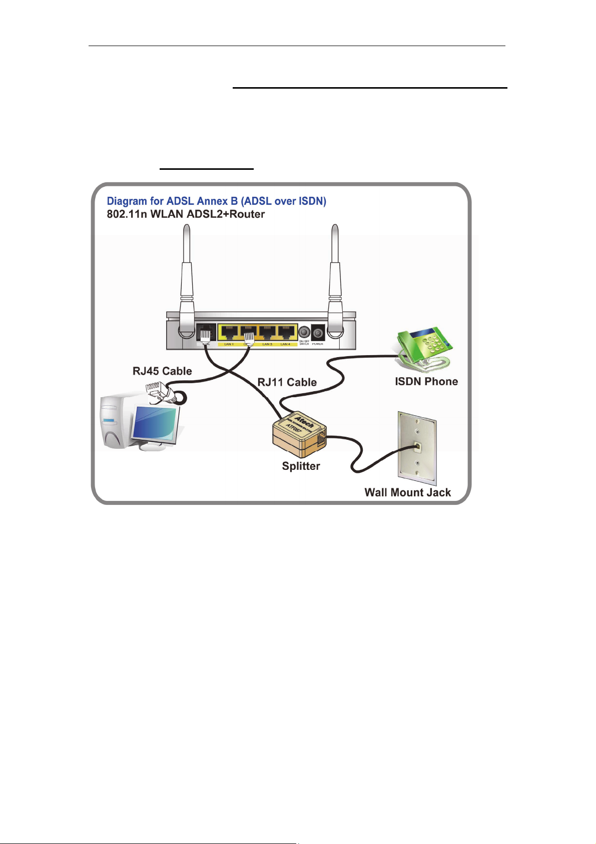
Connection of 802.11n WLAN ADSL2+ Router
If you have an ISDN telephone line
connect the modem router as shown below:
1. Connect the supplied RJ45 Ethernet cable from your PC's Ethernet port to any of the 4
802.11n WLAN ADSL2+ Router's LAN Ports.
2. Connect the supplied RJ11 telephone cable from your home's telephone jack to the
“LINE” port of the supplied splitter. Connect another RJ11 telephone cable to the
“MODEM” port of the splitter and connect the other end of this cable to the LINE port of
your 802.11n WLAN ADSL2+ Router.
supplied RJ11 telephone cable from your home's telephone jack to the “LINE” port of your
802.11n WLAN ADSL2+ Router.)
3. Connect a RJ11 telephone cable to the “PHONE” port of the splitter and connect the other
end to your telephone.
4. Connect the power adapter to the power inlet “POWER” of the 802.11n WLAN ADSL2+
Router and turn the “ON/OFF SWITCH” switch of your 802.11n WLAN ADSL2+ Router on.
(If there is no option Splitter, please connect the
11
Wireless ADSL2+ Router User’s Guide
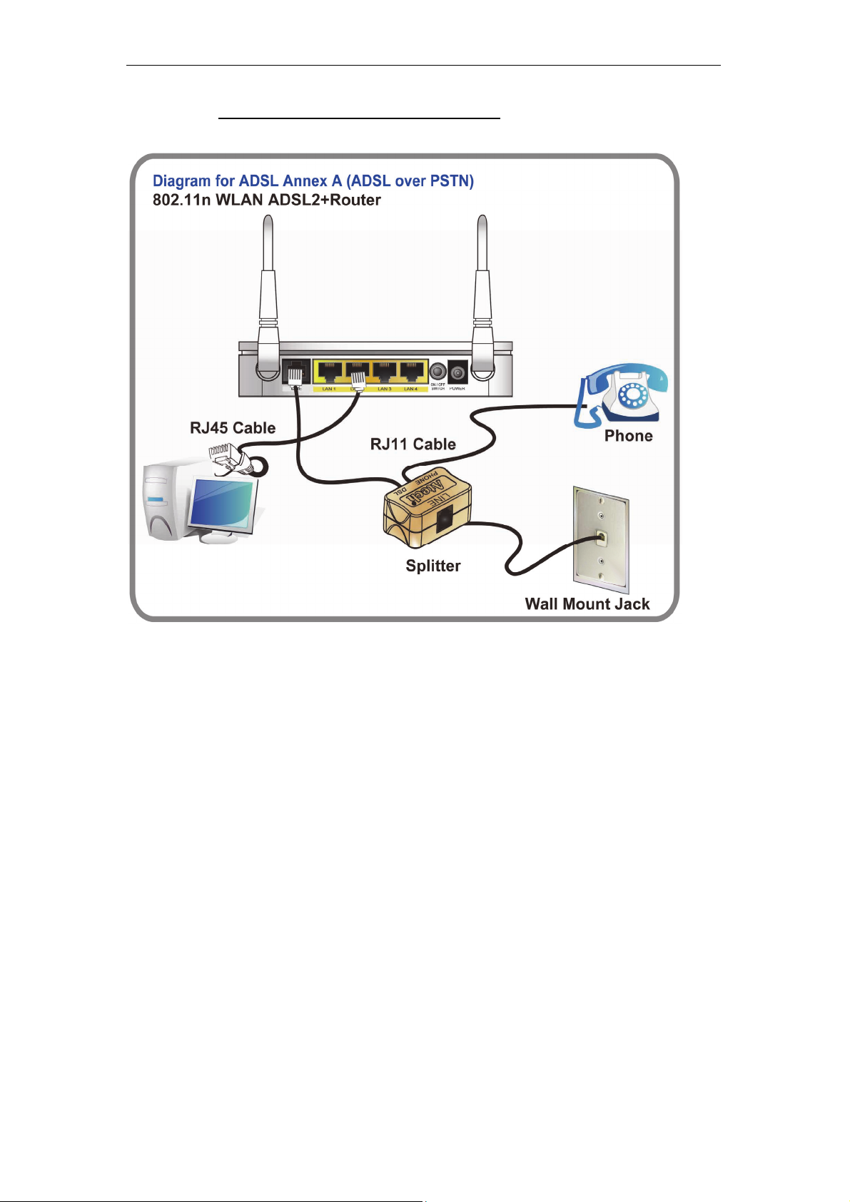
If you have a PSTN telephone line (normal analog line) connect the router as shown
below:
1. Connect the supplied RJ45 Ethernet cable from your PC's Ethernet port to any of the 4
802.11n WLAN ADSL2+ Router's LAN Ports.
2. Connect the supplied RJ11 telephone cable from your home's telephone jack to the
“LINE” port of the supplied splitter. Connect the other supplied RJ11 telephone cable to
the “DSL” port of the splitter and connect the other end of this cable to the “LINE” port of
your 802.11n WLAN ADSL2+ Router. (If there is no option Splitter, please connect the
supplied RJ11 telephone cable from your home's telephone jack to the “LINE” port of your
802.11n WLAN ADSL2+ Router.)
3. Connect a RJ11 telephone cable to the “PHONE” port of the splitter and connect the other
end to your telephone.
4. Connect the power adapter to the power inlet “POWER” of the 802.11n WLAN ADSL2+
Router and turn the “ON/OFF SWITCH” switch of your 802.11n WLAN ADSL2+ Router on.
12
Wireless ADSL2+ Router User’s Guide
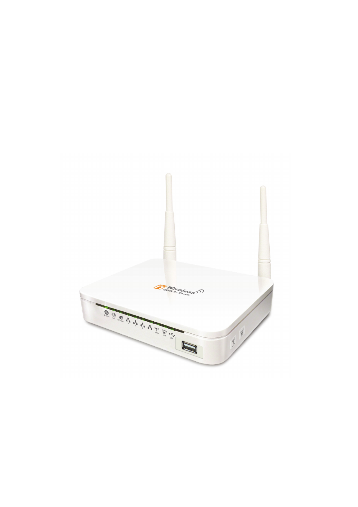
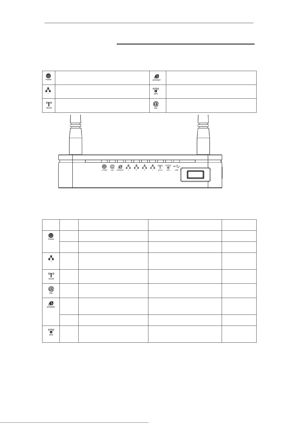
LED meanings & activations
Your 802.11n WLAN ADSL2+ Router has indicator lights on the
front side. Please see below for an explanati on of the f unction of
each indicator light.
Power indicator
Ethernet Active indicator
Wireless Active indicator
Table1. LED function
Internet Active indicator
WPS Active indicator
ADSL Link indicator
Label Color On Flash Off
Red N/A N/A N/A
Green Ready Waiting for device ready Power Off
Green Ethernet Connected Transmit / Receive Data Ethernet
Disconnected
Green WLAN Ready Transmit / Receive Data WLAN Off
Green Connect to DSLAM Disconnect to DSLAM N/A
Green The device has a WAN IP
address from ISP
Transmit / Receive Data N/A
Red N/A N/A N/A
Green N/A Start WPS pairing within 2
minutes
WPS Idle
The icons appear on the products are for application indication
only.
The trademark or intellectual property is belonging to their
respective owners.
13
Wireless ADSL2+ Router User’s Guide
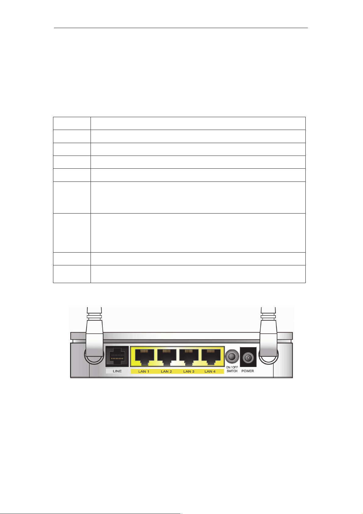
Back Panel Connectors
Table 2 shows the function of each connector and switch of the device.
Table 2. Function / Description of Connectors
Connector Description
POWER
SWITCH
LAN1~4
LINE
RESET
WPS
WLAN
USB
Connects to your 802.11n WLAN ADSL2+ router 12Vac power adaptor
Power Switch
RJ-45 Jack (Ethernet Cable) connection to your PC, or HUB
Connects to your ADSL2+ line – for ADSL2+ Line input
Reset button. RESET the 802.11n WLAN ADSL2+ router to its default
settings.
Press this button for at least 5 full seconds to start to reset it to its default
settings.
Press this button for at least 3 full seconds and the WPS LED will flash to
start WPS.
Now go to the wireless adapter or device and press its WPS button. Make
sure to press the button within 120 seconds (2 minutes) after pressing the
router's WPS button.
Press this button for at least 3 full second to turn off/on wireless signals
Connects the device via 3G USB Dongle modem into Internet. Please refer to
Step5 to configure in detail.
Figure1. Rear View of the 802.11n WLAN ADSL2+ Router
Figure2. WPS and WLAN button
14
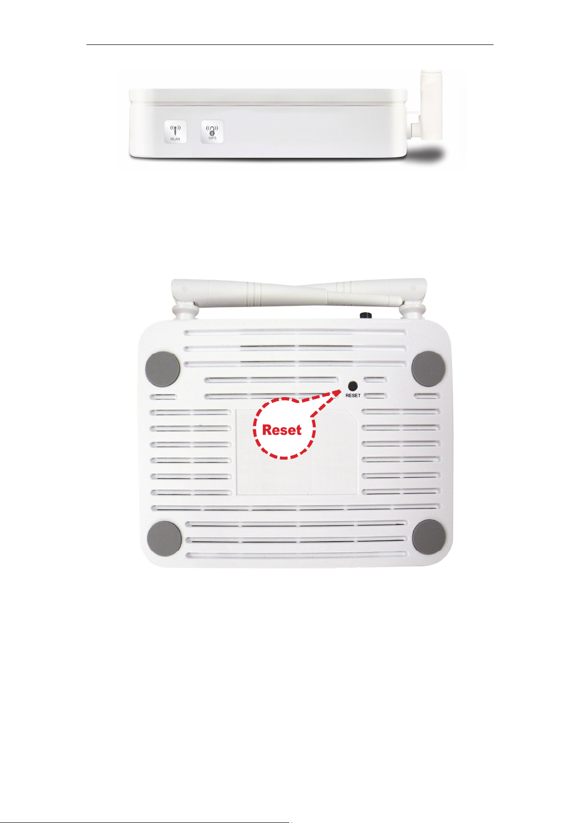
Wireless ADSL2+ Router User’s Guide
Figure3. RESET button
15
Wireless ADSL2+ Router User’s Guide
3 Computer configurations under different OS,
to obtain IP address automatically
Before starting the 802.11n WLAN ADSL2+ Router
configuration, please kindly configu re the PC computer a s
below, to have automatic IP address / DNS Server.
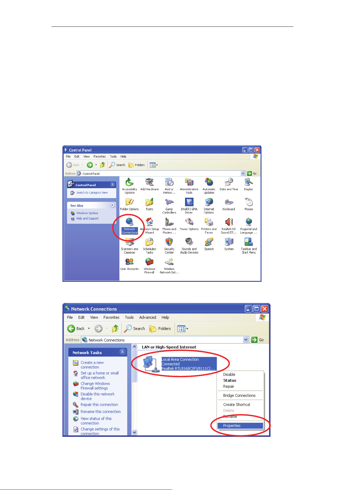
For Windows 98SE / ME / 2000 / XP
1. Click on “Start” -> “Control Panel” (in Classic View). In the Control Panel,
double click on “Network Connections” to continue.
2. Single RIGHT click on “Local Area connection”, then click “Properties”.
16
Wireless ADSL2+ Router User’s Guide
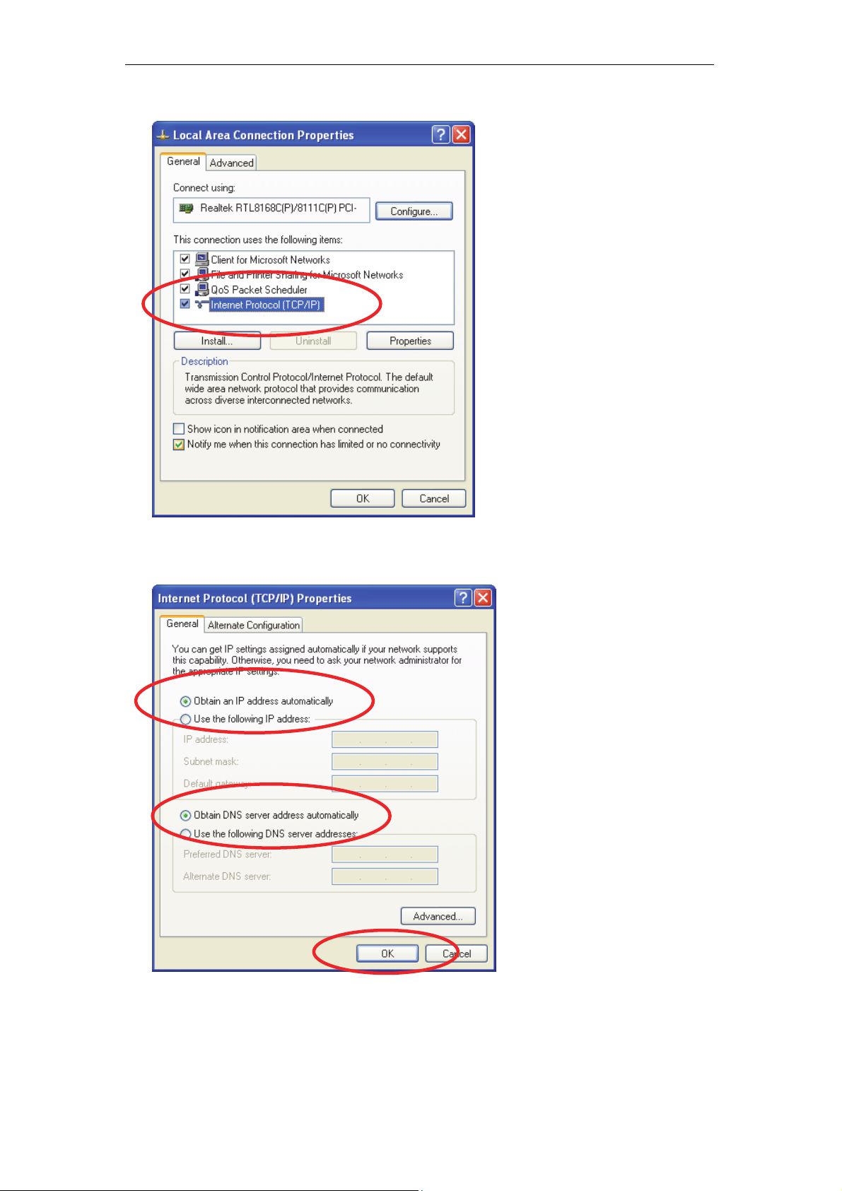
3. Double click on "Internet Protocol (TCP/ IP)".
4. Check "Obtain an IP address automatically" and “Obtain DNS server
address automatically” then click on "OK" to continue.
5. Click "Show icon in notification area when connected" (see screen
image in 3. above) then Click on "OK" to complete the setup procedures.
17
Wireless ADSL2+ Router User’s Guide
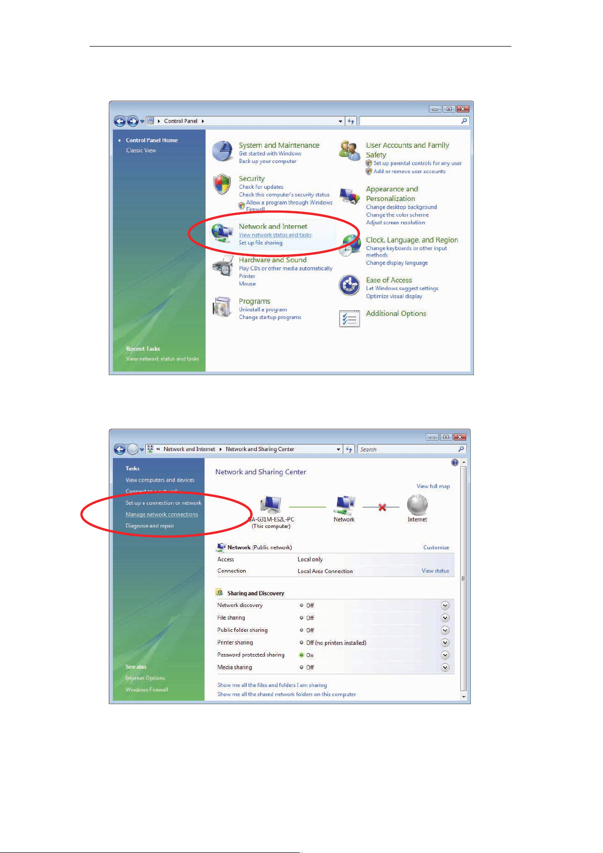
For Windows Vista-32/64
1. Click on “Start” -> “Control Panel” -> “View network status and tasks”.
2. In the Manage network connections, click on “Manage network
connections” to continue.
18
Wireless ADSL2+ Router User’s Guide
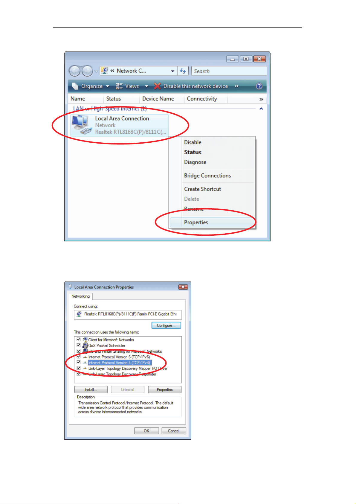
3. Single RIGHT click on “Local Area connection", then click "Properties".
4. The screen will displa y the information “User Account Control” and click
“Continue” to continue.
5. Double click on "Internet Protocol Version 4 (TCP/IPv4)".
19
Wireless ADSL2+ Router User’s Guide
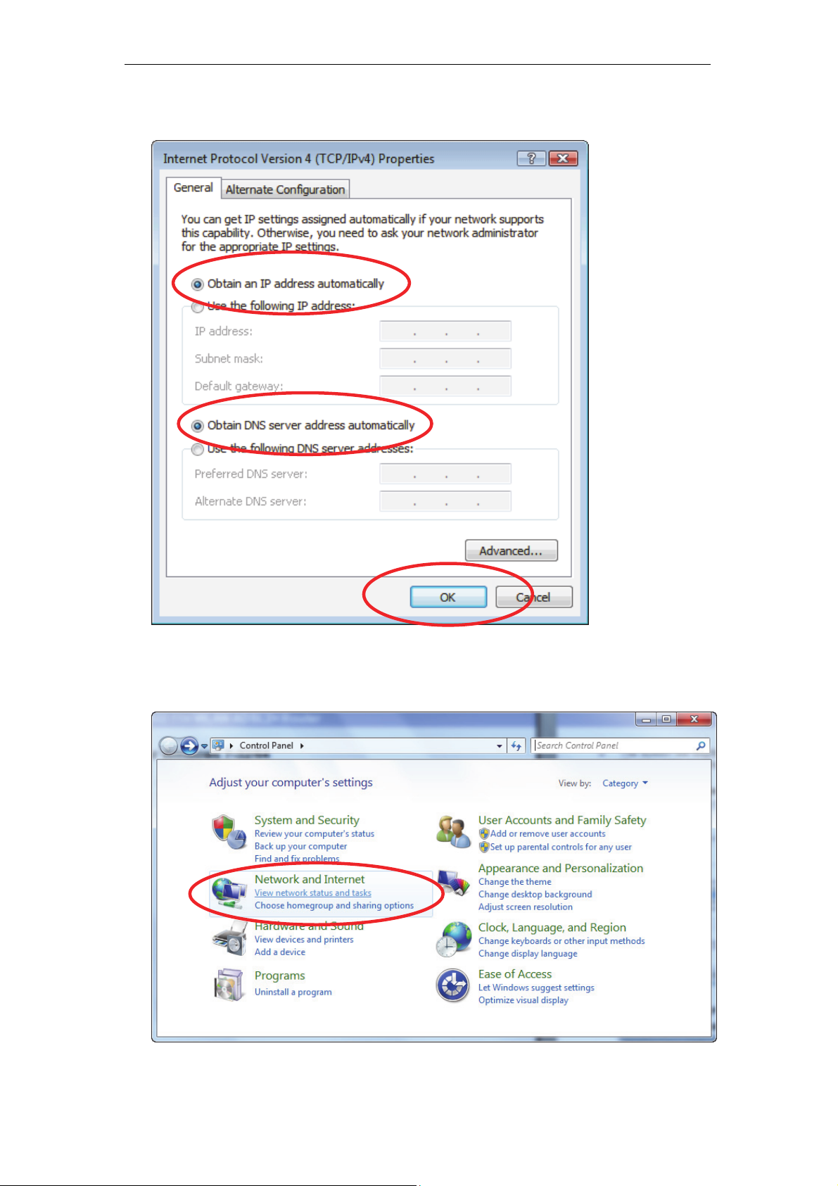
6. Check "Obtain an IP address automatically" and “Obtain DNS server
address automatically” then click on "OK" to continue.
For Windows 7-32/64
1. Click on “Start” -> “Control Panel” (in Category View) -> “View network
status and tasks”.
20
Wireless ADSL2+ Router User’s Guide
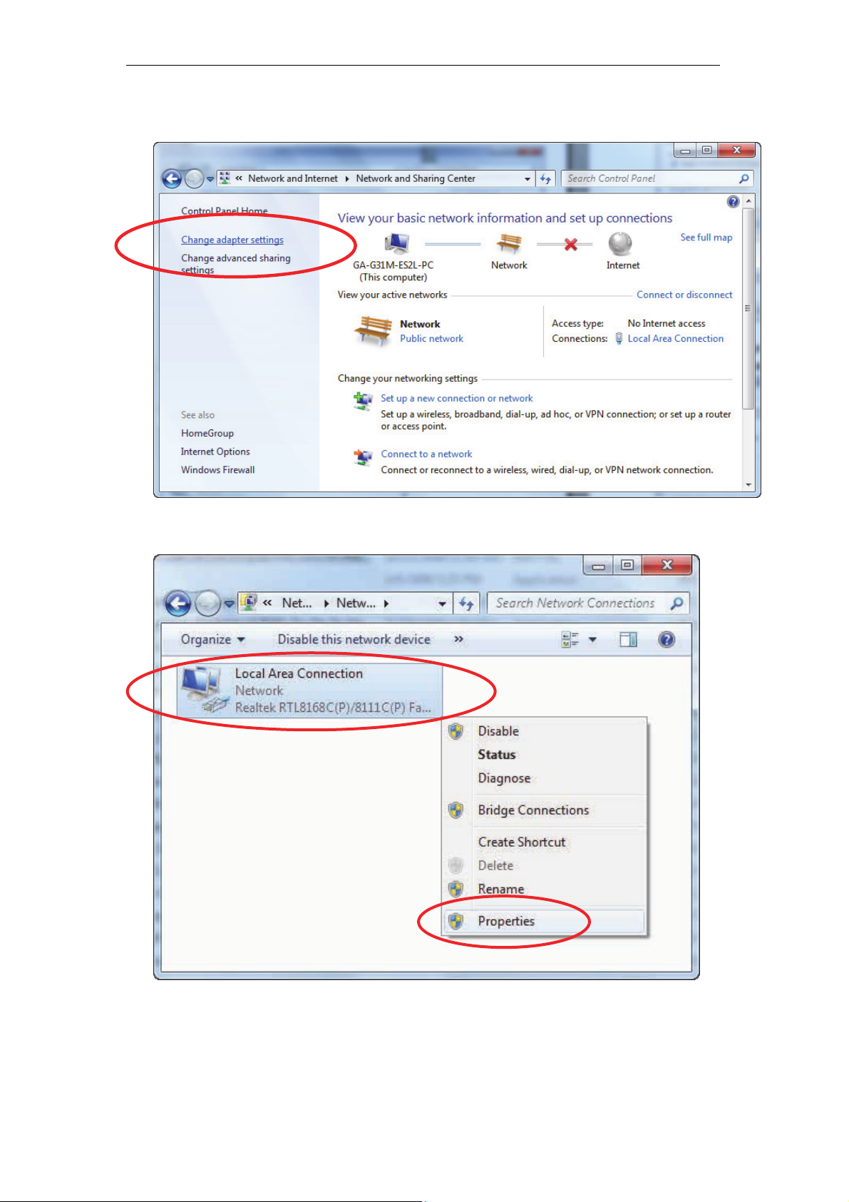
2. In the Control Panel Home, click on “Change adapter settings” to
continue.
3. Single RIGHT click on “Local Area connection", then click "Properties".
21
Wireless ADSL2+ Router User’s Guide
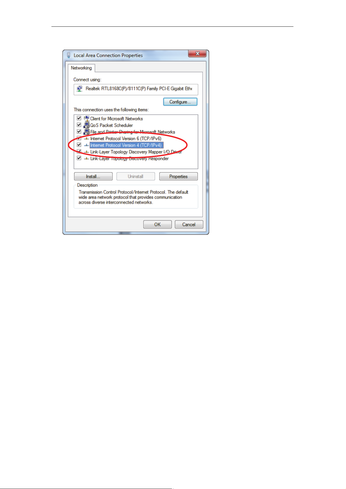
4. Double click on "Internet Protocol Version 4 (TCP/IPv4)".
22

Wireless ADSL2+ Router User’s Guide
5. Check "Obtain an IP address automatically" and “Obtain DNS server
address automatically” then click on "OK" to continue.
23
Wireless ADSL2+ Router User’s Guide
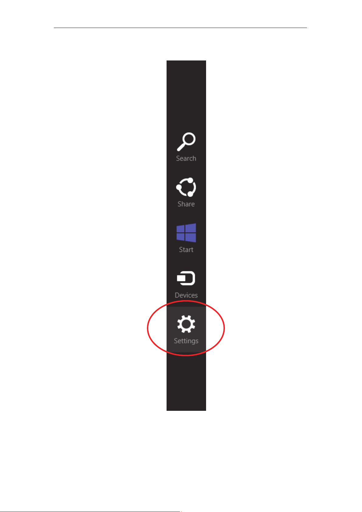
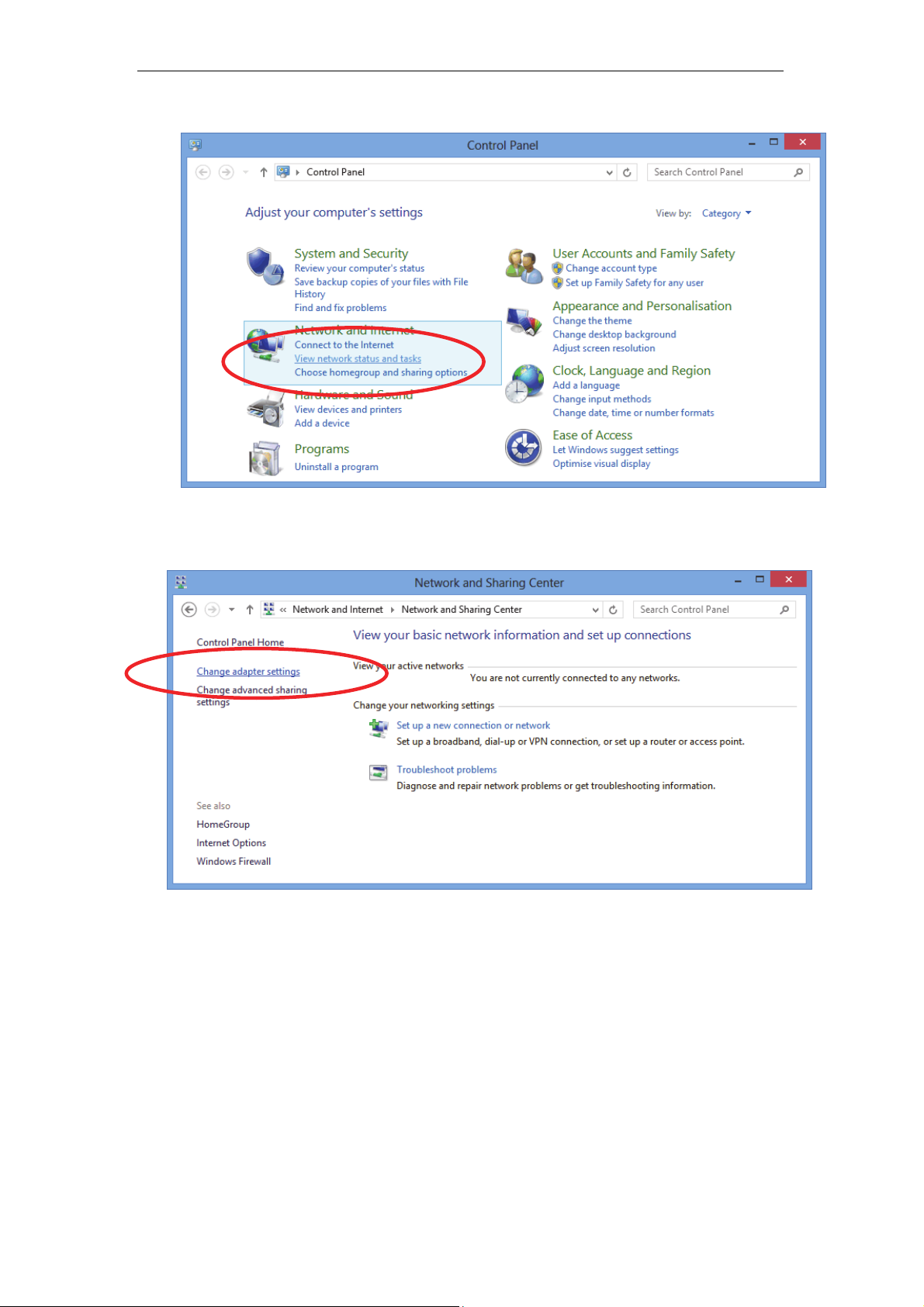
For Windows 8-32/64
1. Move the mouse or tap to the upper right corner and click on “Settings”.
24
Wireless ADSL2+ Router User’s Guide
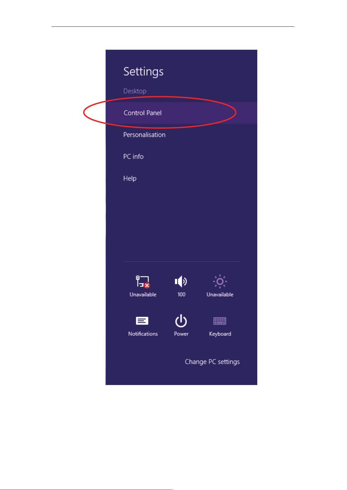
2. Click on “Control Panel”.
25
Wireless ADSL2+ Router User’s Guide
3. Click on “View network status and tasks”.
4. In the Control Panel Home, click on “Change adapter settings” to
continue.
26
Wireless ADSL2+ Router User’s Guide
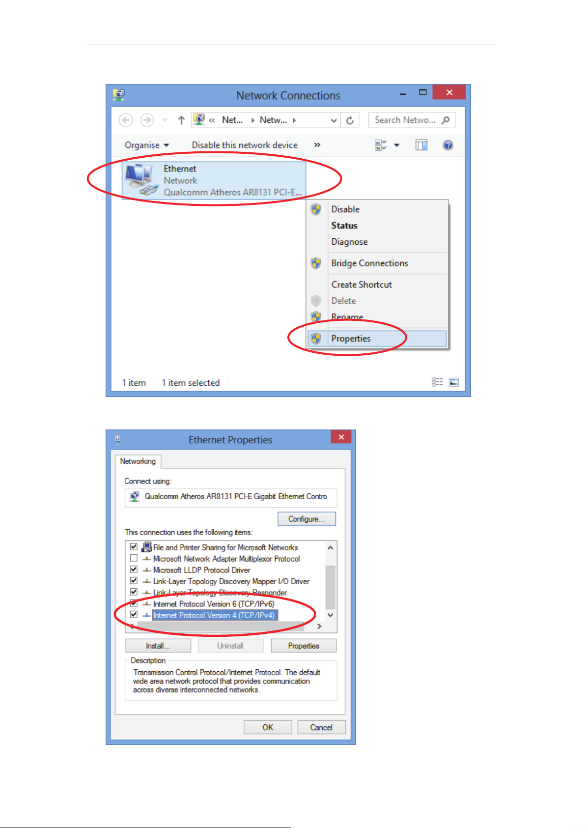
5. Single RIGHT click on “Ethernet", then click "Properties".
6. Double click on "Internet Protocol Version 4 (TCP/IPv4)".
27
Wireless ADSL2+ Router User’s Guide
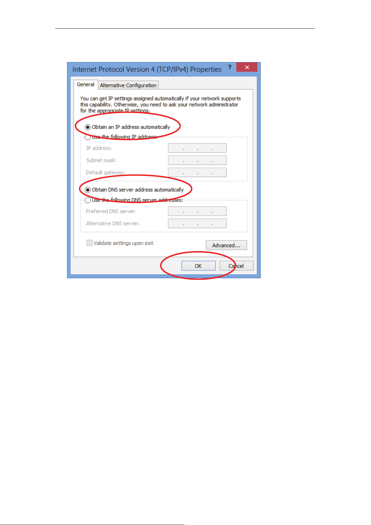
7. Check "Obtain an IP address automatically" and “Obtain DNS server
address automatically” then click on "OK" to continue.
28
Wireless ADSL2+ Router User’s Guide
4 Utility CD execution
Connecting the Hardware
This section describes how to con nect the devi ce to the wall
phone port, the power outlet and your comput er(s) or network.
1. Before you begin to execute utility CD Installations, please
ensure the 802.11n WLAN ADSL2+ Router has been
powered on.
2. Please insert the supplied CD into your CD-ROM drive.
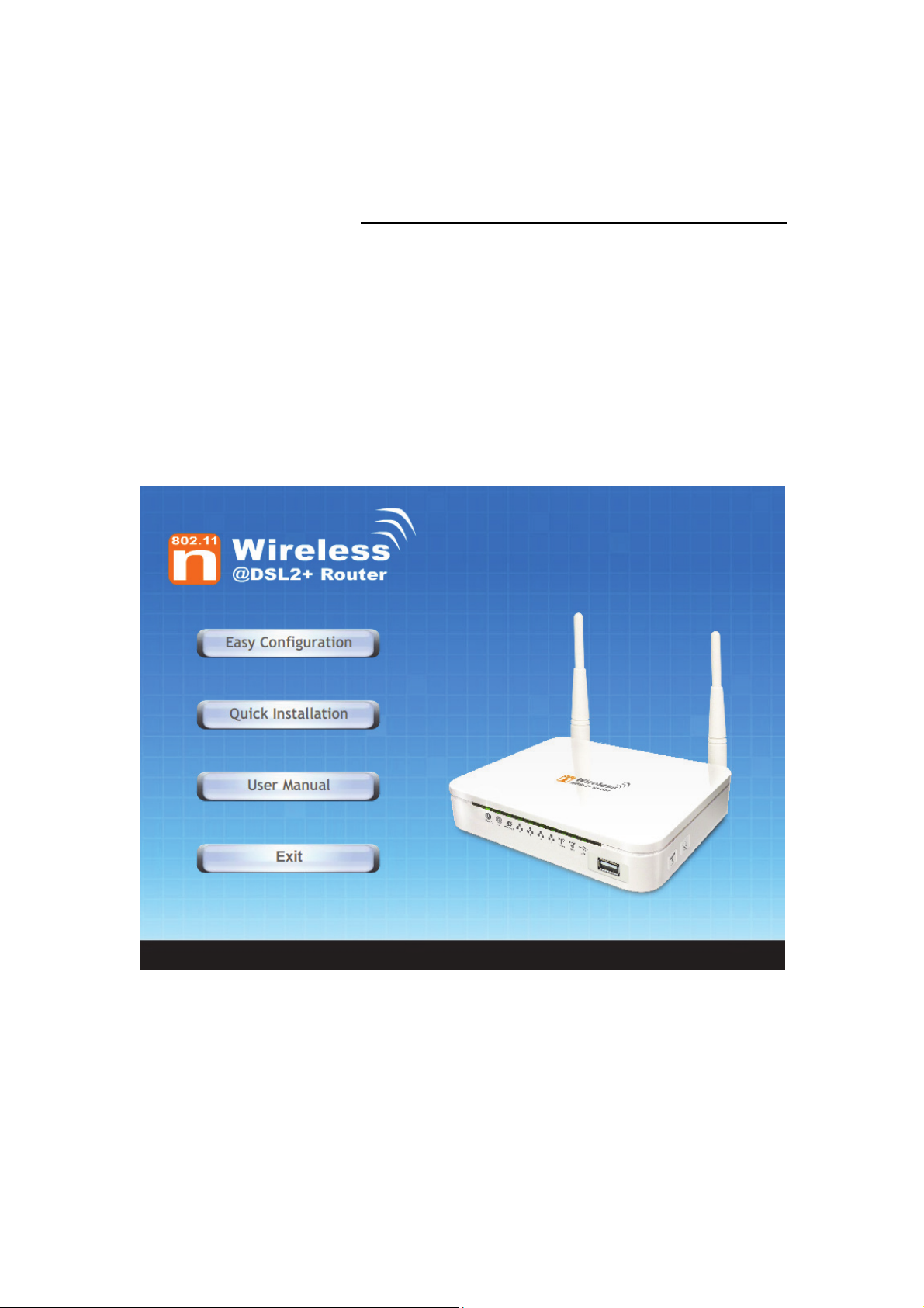
3. The CD should auto-start, displaying the window shown in 4.
below. If your CD does not start automatically, go to
Windows Explorer, Select your CD drive and double click
"Autorun.exe".
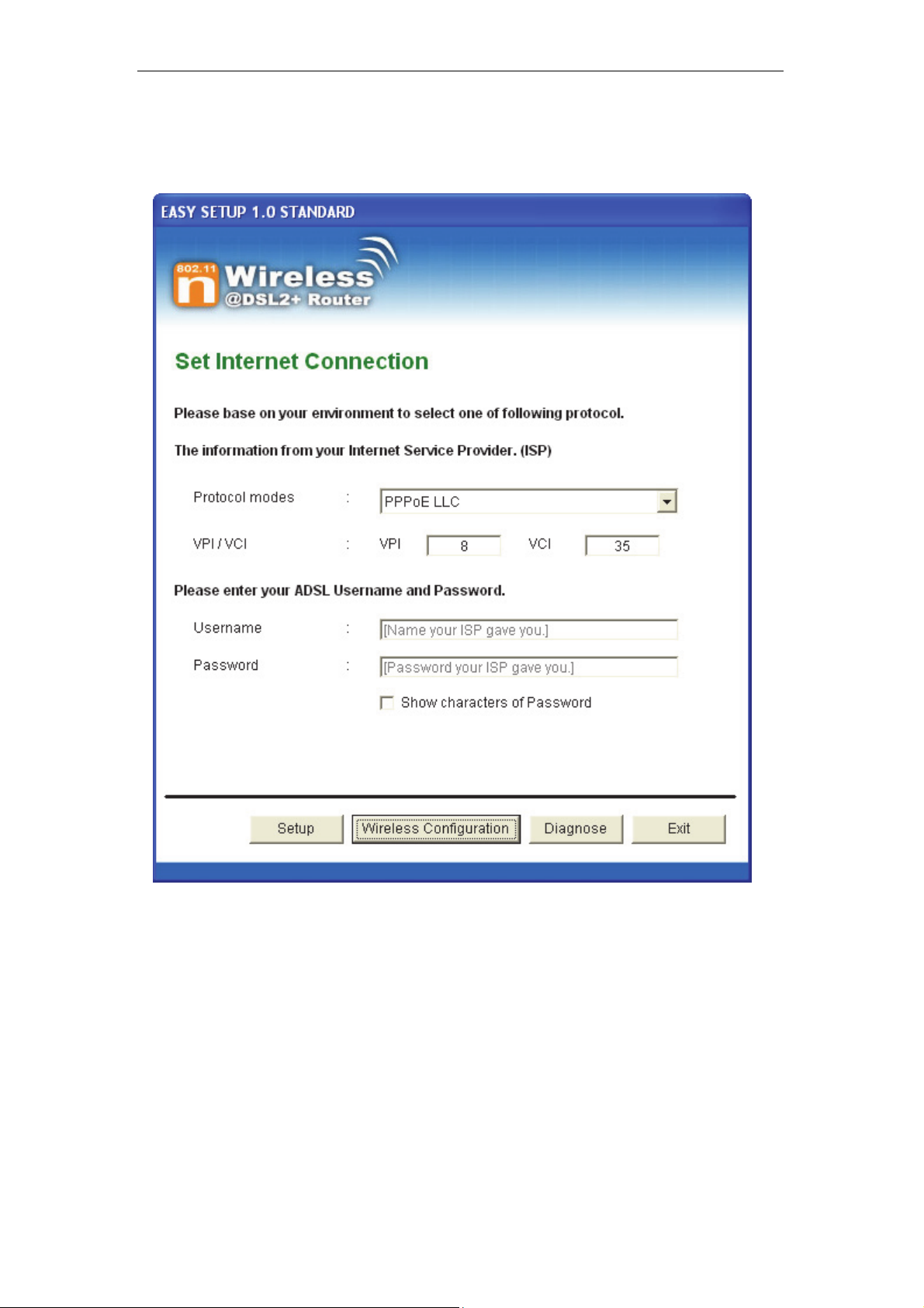
4. To configure the Internet and Wireless configuration, please
click the " Easy Configuration ".
29
Wireless ADSL2+ Router User’s Guide
5. Select Protocol mode and enter the VPI, VCI, Username
and Password your ISP (Internet Services Provider)
provided.
6. Please click “ Wireless Configuration ” button.
30

Wireless ADSL2+ Router User’s Guide
7. Please configure the Wireless Network, Default Channel,
ESSID if you want to change. (Recommended to use
default settings, Wireless Net work = Enable, Default
Channel = Auto, ESSID = 11n_ADSL).
8. Choose the Encryption type if necessary, as Off – No
Encryption / 64 Bit Encryption / 128 Bit Encryption / Wi-Fi
Protected Access2 (AES-CCMP) and W PA Mixed M ode.
(Recommended to use default settings, Encryption
type = Off – No Encryption). For example, y ou choose
Off – No Encryption.
9. Configure related Wireless Configurations and then click
"Submit" button to continue.
31

Wireless ADSL2+ Router User’s Guide
10. Please click “ Setup ” button, when the procedure is
completed, it will start to configure the device for a while.
32

Wireless ADSL2+ Router User’s Guide
11. Now, checking 802.11n WLAN ADSL 2+ Router hardware
connection, ADSL2+ settings, WLAN settings, and ADSL2+
Line connection status.
12. Easy setup configuration completed. Click on " Exit " to exit
this program.
33

Wireless ADSL2+ Router User’s Guide
13. Click on " Exit " to exit this program.
14. Now, the 802.11n WLAN ADSL2+ Router has been
configured completely, and suitable for Wi reless and
Internet Connections.
34

Wireless ADSL2+ Router User’s Guide
Wireless Connection
For easy installation it is saved to keep the settings. Yo u can
later change the wireless settings via the wireless co nfiguration
menu. (see user manual on the CD – Chapter 14 and other).
15. Double click on the wireless icon on your computer and
search for the wireless network th at you e nter ESSI D name.
16. Click on the wireless network that you enter ESSID name
(the default setting ESSID = 11n_ADSL) to connect.
35

Wireless ADSL2+ Router User’s Guide
17. If the wireless network isn’t encrypted, click on "Conne ct
Anyway" to connect.
18. If the wireless network is encrypted, enter the network key
that belongs to your authentication type and key. (the
default settings Security Mode = Disable). Y ou can later
change this network key via the wireless configuratio n
menu. (see user manual on the CD – Chapter 14 and other).
19. Click on "Connect" or "Ap ply".
20. Now you are ready to use the Wireless Network to Internet
or intranet.
36

Wireless ADSL2+ Router User’s Guide
5 USB 3G Configuration (This function may
vary depending on model)
Connecting the Hardware
This section describes how to con nect the devi ce to the wall
phone port, the power outlet and your comput er(s) or network.
Before you begin, turn the power off for all devices. These
include your computer(s), your LAN hub/swit ch (if appli cable),
WARNING
and the Wireless Gateway.
The diagram below illustrates the hardware connections. The
layout of the ports on your device may va ry from the lay out
shown. Refer to the steps that follow for specific instructions.
Step 1. Connect the 3G USB Modem to US B Port
Connect the 3G USB Modem to 802.11n WLAN ADSL2+
Router's USB Port.
Step 2. Connect the Ethernet cable to LAN Port
Connect the supplied RJ45 Ethernet cable from your PC's
Ethernet port to any of the 4 802.11n WLAN ADSL2+
Router's LAN Ports.
Step 3. Attach the power connector
Connect the power adapter to the power inlet “POWER” of
the 802.11n WLAN ADSL2+ Router and turn the po wer
switch “ON/OFF SWITCH” of your 802.11n WLAN ADSL2+
Router on.
* Actual ANTENNA may vary dependin g on model
37

Wireless ADSL2+ Router User’s Guide
USB 3G Configuration
1. Visit web page http://192.168.1.1 and then enter the Login
User Name: admin and Login Password: admin and then
click on OK button.
2. From the head Setup menu, click on 3G:
38

Wireless ADSL2+ Router User’s Guide
3. Enable 3G WAN.
4. Enter PIN code provided by your ISP. Keep it empty if your
ISP doesn't need it
5. Enter Access Point Name (APN) provided by your ISP.
Keep it empty if your ISP doesn't need it
6. Enter Dial Number provided by your ISP. Keep it as default
if your ISP doesn't need it
7. Enter User Name provided by your ISP. Keep it empty if
your ISP doesn't need it
8. Enter Password provided by your ISP. Keep it empty if your
ISP doesn't need it
9. Click Apply Changes.
39

Wireless ADSL2+ Router User’s Guide
10. From the head Setup menu, click on WLAN:
40

Wireless ADSL2+ Router User’s Guide
11. From the Band drop-down list, select a Band.
12. From the Mode drop-down list, select AP setting.
13. Enter SSID for example 11n_ADSL.
41

Wireless ADSL2+ Router User’s Guide
14. From the Channel Width drop-down list, select a Channel
Width.
15. From the ControlSideband drop-down list, select a
ControlSideband.
16. From the Channel Number drop-down list, select a Channel
Number.
17. Click Apply Changes.
18. Click on Security:
42

Wireless ADSL2+ Router User’s Guide
43

Wireless ADSL2+ Router User’s Guide
19. Choose the Encryption type if necessary, as None / WEP /
Wi-Fi Protected Access (TKIP / AES-CCMP) / Wi-Fi
Protected Access2 (TKIP / AES-CCMP) and WPA2 Mixed
Mode. For example, the Encryption you cho ose is None.
20. Click Apply Changes.
21. Change setting successfully! Click Save button.
22. Now you are ready to use the USB 3G to Internet.
44

Wireless ADSL2+ Router User’s Guide
6 Getting S tarted with the W eb pages
The Wireless ADSL2+ Router includes a series of Web pages
that provide an interface to the software in stalle d on the device.
It enables you to configure the d evice sett ings to meet th e
needs of your network. You can access it through your web
browser from any PC connected to the device via
Accessing the Web pages
To access the Web pages, you need the following:
• A PC or laptop connected to the LAN port on the device.
• A web browser installed on t he PC. T he minim um bro wser
version requirement is Internet Explorer v4 or Netscape v4.
For the best display quality, use latest version of Internet
Explorer, Netscape or Mozilla Firefox.From any of the LAN
computers, launch your web browser, type the following
URL in the web address (or location) box, and press [Enter]
on your keyboard:
http://192.168.1.1
the LAN ports.
The Status homepage for the web pages is displayed:
45

Wireless ADSL2+ Router User’s Guide
Figure 1: Homepage
46

Wireless ADSL2+ Router User’s Guide
The first time that y ou click o n an en try from the l efthand menu, a login box is display ed. You must enter
your username and password to access the pages.
A login screen is displayed:
Note
Figure 2: Login screen
1. Enter your user name and password. The first time you log
into the program, use these defaults:
User Name:
Password:
You can change the password at any time or you can configure your
device so that you do not need to enter a password. See Password.
2. Click on OK. You are now ready to configure your device.
This is the first page display ed ea ch time you log in t o the We b
pages. This page contains links to the following pages:
• Addressing; links to the Addressing page that controls your
device’s network address. See Addressing.
• Internet Access; links to the Internet Access page that
controls how your device conne cts to the I nternet. Se e
Internet Access.
admin
admin
Note
If you receive an error message or the Welcome page is not
displayed, see Troubleshooting Suggestions.
47

Wireless ADSL2+ Router User’s Guide
Testing your Setup
Once you have connected your hardware and configured your
PCs, any computer on your LAN should be able to use the
device’s DSL connection to access the Internet.
To test the connection, turn on the device, wait for 30 seconds
and then verify that the LEDs are illum inated as follo ws:
Table 1. LED Indicators
LED Behavior
POWER
ETH
Link
INTERNET
Solid green to indicate that the device is turned on. If this
light is not on, check the power cable attachment.
Flashing on/off while the device is booting. After about 1015 seconds, solid green to indicate that the device can
communicate with your LAN.
Flashing on/off while data is being transmitted. Solid green
to indicate that the device has successfully established a
connection with your ISP.
Flashing on/off while data is being transferred. Solid green
when a valid IP address has been assigned to the device
by the ISP.
If the LEDs illuminate as expe cted, test yo ur Internet connecti on
from a LAN computer. To do this, open your web browser, and
type the URL of any external website (such as
http://www.yahoo.com
). The LED labeled INTERNET should
blink rapidly and then appear solid as the device connects to the
site.
If the LEDs do not illuminate as expected, you may need to
configure your Internet access setti ngs usi ng the info rmation
provided by your ISP. For details, see Internet Access. If the
LEDs still do not illuminate as expected or the web page is n ot
displayed, see Troubleshooting Suggestions or contact your
ISP for assistance.
Default device settings
In addition to handling the DSL connect ion to y our ISP , the DSL
Modem can provide a variety of se rvices t o your net work. Th e
device is preconfigured with default settings for use with a
typical home or small office network.
The table below lists some of the m ost importa nt default settings;
these and other features are described fu lly in the subs equent
chapters. If you are familiar with network configurat ion, revie w
these settings to verify that they meet the needs of your network.
Follow the instructions to change them if necessary. If you are
unfamiliar with these settings, t ry using t he devi ce witho ut
modification, or contact your ISP for assistance.
We strongly recommend that you conta ct your ISP prior to
changing the default configuration.
WARNING
48

Wireless ADSL2+ Router User’s Guide
Option Default Setting Explanation/Instructions
LINE Port IP
Address
Unnumbered interface:
192.168.1.1
Subnet mask:
This is the temporary public IP address of the WAN
port on the device. It is an unnumbered interface that
is replaced as soon as your ISP assigns a ‘real’ IP
address. See Internet Access.
255.255.255.255
LAN Port
IP Address
Assigned static IP address:
192.168.1.1
Subnet mask:
This is the IP address of the LAN port on the device.
The LAN port connects the device to your Ethernet
network. Typically, you will not need to change this
address. See LAN.
255.255.255.0
DHCP (Dynamic
Host Configuration
Protocol)
DHCP server enabled with the
following pool of addresses:
192.168.1.64
through
192.168.1.253
The Wireless ADSL2+ Router maintains a pool of
private IP addresses for dynamic assignment to your
LAN computers. To use this service, you must have
set up your computers to accept IP information
dynamically, as described in Services -> DHCP
Settings.
NAT (Network
Address Translation)
NAT enabled
Your computers’ private IP addresses (see DHCP
above) will be translated to your public IP address
whenever the PCs access the Internet. See Services
-> Firewall.
49


Wireless ADSL2+ Router User’s Guide
7 Overview
The Overview page displays useful informati on about the set up
of your device, including:
• details of the device’s Int ernet acce ss settin gs
• version information about your device
To display this page:
From the head menu, click on Status. The following page is
displayed:
51

Wireless ADSL2+ Router User’s Guide
Figure 3: Overview page
52

Wireless ADSL2+ Router User’s Guide
The information displayed on this page is explained in detail in
the following sections.
Internet access settings
This section displays details of the setting s that allow your
device to access the Int ernet . Thes e detail s in clude:
IP address and
subnet mask:
Default gateway: The address of the ISP server through
DNS servers: The Domain Name System (DNS)
Your ISP assigns all of these set tings. I n most ca ses, you will
not need to make changes to these settings in order for your
Internet connection to work. If your ISP does ask you to change
any of these settings, follow the instructions for manu ally
configuring your device in Internet Access.
The IP address and subnet mask
assigned to your WAN interface. This
address is used temporarily until your
ISP assigns a real IP address (via DHCP
or PPP – see Internet Access.
which your Internet connection will be
routed.
servers used by your ISP to map domain
names to IP addresses.
About Wireless ADSL2+ Router
This section displays details of your device’s hardware and
firmware versions. If you need to contact your ISP’s support
team, they may need to know which hardware/firmware
versions you are using in order to answer your query.
Your hardware version details contain i nformati on about the
make and model of your device and its exact ha rdware
components.
Your firmware version details cont ain informati on about t he
software program running on your device. They then make the
latest updated version avail able to y ou via the I nternet. F or
details of how to update your firmware, see Maintenance ->
Upgrade Firmware.
53

Wireless ADSL2+ Router User’s Guide
8 S tatus
You can view statistics on the processing of IP packets on the
networking interfaces. You will not ty picall y need to v iew this
data, but you may find it helpful when working with your ISP to
diagnose network and Internet data transmission problems.
Device Info
This page shows the current status and some basic settings of
the device.
1. From the head Status menu, The following page is
displayed:
2. To display updated statistics showing any new data since
you opened this page, click Refresh.
54

Wireless ADSL2+ Router User’s Guide
55

Wireless ADSL2+ Router User’s Guide
ADSL
This page shows the ADSL line statistic information.
3. From the head Status menu, click on ADSL The following
page is displayed:
4. To display updated statistics showing any new data since
you opened this page, click Refresh.
56

Wireless ADSL2+ Router User’s Guide
Statistics
This page shows the packet statistics for transmission and
reception regarding to netw ork inte rface.
1. From the head Status menu, click on Statistics The
following page is displayed:
2. To display updated statistics showing any new data since
you opened this page, click Refresh.
57

Wireless ADSL2+ Router User’s Guide
9 Internet Access
This chapter describes how to config ure the way that your
device connects to the Internet. Your ISP determines what type
of Internet access you should use and provides you with any
information that you need in order to co nfigure the I nternet
access to your device.
Your device needs the following address information in order to
access the Internet:
ATM PVC To configure ATM PVC, enter the VPI
and VCI provided by ISP. Select the
Service Type Index, Service Cate gory
and enter the following information:
• Peak Cell Rate
• Sustainable Cell Rate
• Maximum Burst Size
Connection Type To configure the connection type, select
the protocol and encapsulation type as
indicated by ISP. Supported Protocol
types are:
• RFC1483 Bridged
• RFC1483 MER
• PPPoE
• PPPoA
• RFC1483 Routed
Supported Encapsulation types are:
• VCMUX
• LLC/SNAP
WAN IP Settings To configure WAN IP settings, enter the
information as indicated by ISP.
Enable/Disable the Access Concentrator
option. Either enter the WAN IP or select
the option to automatically obtain IP
address.
Check as applicable the following two
options:
• Enable NAT
• Add default Route
Broadband
Username and
Password
58
To configure Broadband Username and
Password, enter the user name and
password details. Also set the session
establishment condition as one of the
following:
• Continuous

Wireless ADSL2+ Router User’s Guide
• Connect on demand. Enter the
minutes after which the sessio n
must be disconnected, if no
activity takes place.
• Manual. Enter the minutes after
which the session must be
disconnected, if no activity takes
place.
In most cases, you will not need to configure your device with
these addresses because your ISP is likely to use an Internet
access type which automatically assigns addresses to your
device. For more information, se e Types of Internet Access.
Types of Internet Access
The types of Internet access available are as follows:
• PPP Internet access – your device uses a Point to Point
Protocol (PPP) to carry data between your ISP and your
computer. To use PPP Internet access, you must enter a
PPP login username and password the first time to log
on. The IP addresses required to access your ISP’s
Internet service are automatically configure d.
Your device supports PPPoE (over Ethernet).
• PPP Internet access – your device uses a Point to Point
Protocol (PPP) to carry data between your ISP and your
computer. To use PPP Internet access, you must enter a
PPP login username and password the first time to log
on. The IP addresses required to access your ISP’s
Internet service are automatically configure d.
Your device supports PPPoA (over ATM).
• Bridged Internet access – your device uses a B ridge mode
with yo u r P P P o E C l i e n t Software to carry data between
your ISP and your computer. To use Bridged Internet
access with your P PPoE Client Software, you must enter
a PPP login username and password the first time to log
on. The IP addresses required to access your ISP’s
Internet service are automatically configure d.
Your device supports RFC 1483 Bridged Mode).
59

Wireless ADSL2+ Router User’s Guide
Configuring your PPPoE DSL connection
If your ISP’s Internet service uses PPPoE you need to set up a
PPP login account. The first time that you login to the Internet,
your ISP will ask you to enter a username and password so
they can check that you are a l egitimat e, registe red Int ernet
service user. Your device stores these authenti cation detail s, so
you will not have to enter this username and password every
time you login.
Your ISP may also tell you to set unique path and circuit
numbers (called VPI and VCI) in order to connect your device to
the ISP’s Internet service. In most ca ses, your dev ice will u se
default settings, so you may not need to enter these values.
Note
Your ISP will provide you with the login details and VPI/VCI
values necessary to set up a PPP login account.
If your ISP wants you to connect to the Internet using PPP,
follow the instructions below.
60
Wireless ADSL2+ Router User’s Guide
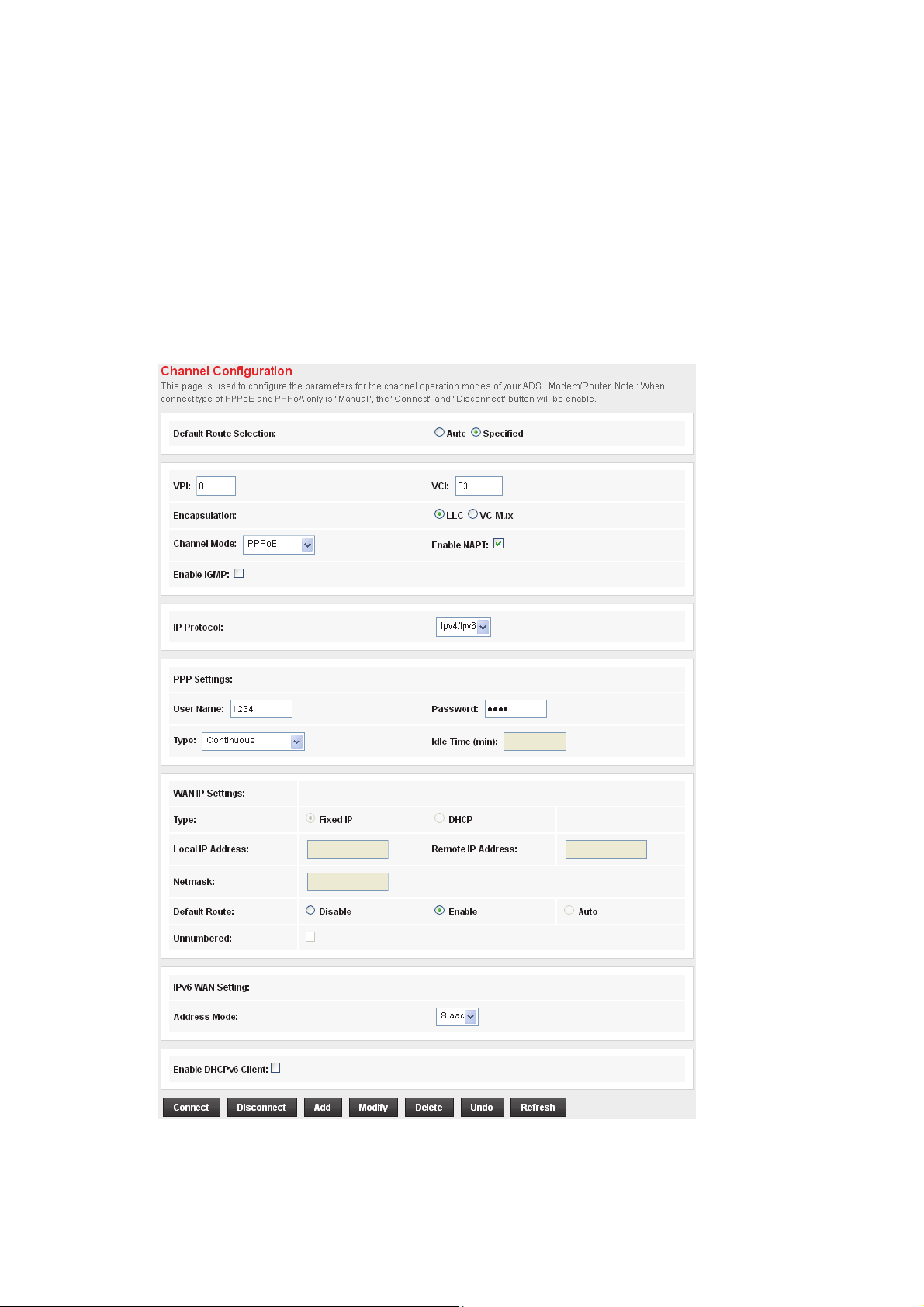
1. From the head Setup menu, click on WAN. The following
page is displayed:
2. Enter VCI and VPI setting determined by your ISP.
3. Select the Encapsulation determined by your ISP.
4. From the Channel Mode drop-down list, select PPPoE
setting.
5. From the IP Protocol drop-down list, select the IP Protocol,
IPv4, IPv6 or dual stacks IPv4/IPv6 determined by your ISP.
6. Enter User Name/Password provided by your ISP. Type
them in the relevant boxes.
7. IPv6 WAN setting determined by your ISP.
8. If you are happy with your settings, click Add
9. Your configuration is complete.
10. Now you are ready to Surf the Internet !!!
61

Wireless ADSL2+ Router User’s Guide
Configuring your PPPoA DSL connection
If your ISP’s Internet service uses PPPoA you need to set up a
PPP login account. The first time that you login to the Internet,
your ISP will ask you to enter a username and password so
they can check that you are a l egitimat e, registe red Int ernet
service user. Your device stores these authenti cation detail s, so
you will not have to enter this username and password every
time you login.
Your ISP may also tell you to set unique path and circuit
numbers (called VPI and VCI) in order to connect your device to
the ISP’s Internet service. In most ca ses, your dev ice will u se
default settings, so you may not need to enter these values.
Note
Your ISP will provide you with the login details and VPI/VCI
values necessary to set up a PPP login account.
If your ISP wants you to connect to the Internet using PPP,
follow the instructions below.
62

Wireless ADSL2+ Router User’s Guide
1. From the head Setup menu, click on WAN. The following
page is displayed:
2. Enter VCI and VPI setting determined by your ISP.
3. Select the Encapsulation determined by your ISP.
4. From the Channel Mode drop-down list, select PPPoA
setting.
5. From the IP Protocol drop-down list, select the IP Protocol,
IPv4, IPv6 or dual stacks IPv4/IPv6 determined by your ISP.
6. Enter User Name/Password provided by your ISP. Type
them in the relevant boxes.
7. IPv6 WAN setting determined by your ISP.
8. If you are happy with your settings, click Add
9. Your configuration is complete.
10. Now you are ready to Surf the Internet !!!
63

Wireless ADSL2+ Router User’s Guide
Configuring your Bridged DSL connection
1. From the head Setup menu, click on WAN. The following
page is displayed:
2. Enter VCI and VPI setting determined by your ISP.
3. Select the Encapsulation determined by your ISP.
4. From the Channel Mode drop-down list, select 1483
Bridged setting.
5. If you are happy with your settings, click Add
6. Now you can load your PPPoE Client Software onto your
PC.
7. Now you can load your PPPoE Client Software with user
name and password which determined by your ISP onto
your PC.
64

Wireless ADSL2+ Router User’s Guide
Configuring your 1483 MER by DHCP
1. From the head Setup menu, click on WAN. The following
page is displayed:
2. Enter VCI and VPI setting determined by your ISP.
3. Select the Encapsulation determined by your ISP.
4. From the IP Protocol drop-down list, select the IP Protocol,
IPv4, IPv6 or dual stacks IPv4/IPv6 determined by your ISP.
5. From the Channel Mode drop-down list, select 1483 MER
setting.
6. From the Type ratio, click DHCP.
7. IPv6 WAN setting determined by your ISP.
8. If you are happy with your settings, click Add
9. Your configuration is complete.
10. Now you are ready to Surf the Internet !!!
65

Wireless ADSL2+ Router User’s Guide
Configuring your 1483 MER by Fixed IP
1. From the head Setup menu, click on WAN. The following
page is displayed:
2. Enter VCI and VPI setting determined by your ISP.
3. Select the Encapsulation determined by your ISP.
4. From the Channel Mode drop-down list, select 1483 MER
setting.
5. From the IP Protocol drop-down list, select the IP Protocol,
IPv4, IPv6 or dual stacks IPv4/IPv6 determined by your ISP.
6. From the Type ratio, click Fixed IP.
7. Enter Local IP Address, Subnet Mask and Remote IP
Address which was given by Telecom or by your Internet
Service Provider (ISP).
8. IPv6 WAN setting determined by your ISP.
9. If you are happy with your settings, click Add
10. From the head Service menu, click on DNS.
66

Wireless ADSL2+ Router User’s Guide
11. Check on Set DNS Manually ratio.
12. Enter DNS setting determined by your ISP.
13. Click Apply Changes button.
14. Your configuration is complete.
15. Now you are ready to Surf the Internet !!!
67

Wireless ADSL2+ Router User’s Guide
3G Settings
This page is used to configure the parameters for your 3G
network access. .
1. From the left-hand WAN menu, click on 3G. The following
page is displayed:
68

Wireless ADSL2+ Router User’s Guide
Field Description
PIN
APN
Dial Number
User Name
Password
Enter PIN code determined by your ISP. Keep it empty
if your ISP doesn't need it
Enter Access Point Name (APN) determined by y our
ISP. Keep it empty if your ISP doesn't need it
Enter Dial Number determined by your ISP. Keep it as
default if your ISP doesn't need it
Enter User Name determined by your ISP. Keep it
empty if your ISP doesn't need it
Enter Password determined by your ISP. Keep it
empty if your ISP doesn't need it
69

Wireless ADSL2+ Router User’s Guide
ATM Settings
The page is for ATM PVC QoS par ameters setting. T he DSL
device support 4 QoS mode —CBR/rt-VBR/nrt-VBR/UBR.
1. From the left-hand WAN menu, click on ATM. The following
page is displayed:
Field Description
70

Wireless ADSL2+ Router User’s Guide
VPI
VCI
QoS
PCR
SCR
MBS
Virtual Path Identifier. This is read-only field and is
selected on the Select column in the Current ATM VC
Table.
Virtual Channel Identifier. This is read-only field and is
selected on the Select column in the Current ATM VC
Table. The VCI, together with VPI, is used to identify
the next destination of a cell as it passes through to the
ATM switch.
Quality of Server, a characteristic of data transmission
that measures how accurately and how quickly a
message or data is transferred from a source host to a
destination host over a network. The four QoS options
are:
−UBR (Unspecified Bit Rate): When UBR is selected,
the SCR and MBS fields are disabled.
−CBR (Constant Bit Rate): When CBR is selected, the
SCR and MBS fields are disabled.
−nrt-VBR (non-real-time Variable Bit Rate): When nrtVBR is selected, the SCR and MBS fields are enabled.
−rt-VBR (real-time Variable Bit Rate): When rt-VBR is
selected, the SCR and MBS fields are enabled.
Peak Cell Rate, measured in cells/sec., is the cell rate
which the source may never exceed.
Sustained Cell Rate, measured in cells/sec., is the
average cell rate over the duration of the connection.
Maximum Burst Size, a traffic parameter that specifies
the maximum number of cells that can be transmitted
at the peak cell rate.
Function Button Description
Apply Changes
Undo Discard your settings.
Set new PVC OoS mode for the selected PVC. New
parameters will take effect after save into flash
memory and reboot the system. See section “Admin”
for save details.
71

Wireless ADSL2+ Router User’s Guide
ADSL Settings
The ADSL setting page allows you to select any co mbination of
DSL training modes.
1. From the left-hand WAN menu, click on ADSL Settings.
The following page is displayed:
72

Wireless ADSL2+ Router User’s Guide
Field Description
ADSL modulation Choose prefered xdsl standard protocols.
AnnexL Option Enable/Disable ADSL2/ADSL2+ Annex L capability.
AnnexM Option Enable/Disable ADSL2/ADSL2+ Annex M capability.
ADSL Capability “Bitswap Enable” : Enable/Disable bitswap capability.
G.lite : G.992.2 Annex A
G.dmt : G.992.1 Annex A
T1.413 : T1.413 issue #2
ADSL2 : G.992.3 Annex A
ADSL2+ : G.992.5 Annex A
“SRA Enable” : Enable/Disable SRA (seamless rate
adaptation) capability.
Function Button Description
Tone Mask
Apply Changes
Choose tones to be masked. Mased tones will not
carry any data.
Click to save the setting to the configuration and the
modem will be retrained.
73


User’s Guide Configuring your Computers
10 Local Network Configuration
The Addressing page displays information about your LAN IP
address and allows you to change the address and subnet
mask assigned to your device.
You should only change the addressing details if your ISP asks
Note
you to, or if you are familiar with network configuration. In mo st
cases, you will not need to make any changes to this
configuration.
Changing the LAN IP address and subnet mask
1. From the head Setup menu, click on LAN. The following
page is displayed:
75

User’s Guide Configuring your Computers
76

User’s Guide Configuring your Computers
2. From the left-hand LAN menu, click on DHCP Settings.
77

User’s Guide Configuring your Computers
3. Change the IP Pool Range and then clic k Apply Changes
button.
4. Change setting successfully! Click OK button.
78

User’s Guide Configuring your Computers
5. From the left-hand LAN menu, click on LAN.
6. Type a new IP Address and Subnet Mask.
7. Click Apply Changes.
8. Please click 10.0.0.2 to continue configuration.
9. The primary IP address is being changed to 10.0.0. 2
netmask 255.255.255.0. Th en ple ase go to htt p://10. 0.0.2 to
continue. Your browser communicates with the web server
via the LAN connection, and changing the IP address may
disrupt this.
You may also need to renew your DHCP lease:
Windows 95/98
a. Select Run... from the Start menu.
b. Enter winipcfg and click OK.
c. Select your ethernet adaptor from the pull-down menu
d. Click Release All and then Renew All.
e. Exit the winipcfg dialog.
Windows NT/Windows 2000/Windows XP
a. Bring up a command window.
b. Type ipconfig /release in the command window.
c. Type ipconfig /renew.
d. Type exit to close the command window.
Linux
a. Bring up a shell.
b. Type pump -r to release the lease.
c. Type pump to renew the lease.
79

User’s Guide Configuring your Computers
Note
If you change the LAN IP address of the device while conne cted
through your Web browser, you will be disconnected. You must
open a new connection by entering your new LAN IP address as
the URL.
10. From the left-hand menu, click on Save.
Adding the Secondary LAN IP address and subnet
mask
1. From the left-hand LAN menu, click on LAN.
2. Check on Secondary IP.
3. Type the Secondary IP Address and Subnet Mask.
4. Click Apply Changes.
5. From the left-hand menu, click on Save.
80

User’s Guide Configuring your Computers
11 DHCP Settings
You can configure your network and DSL device to use the
Dynamic Host Configuration Protocol (DHCP). This page
provides DHCP instructions for implementing it on your network
by selecting the role of DHCP protocol that this device wants to
play. There are two different DHCP roles t hat this d evice can act
as: DHCP Serve and DHCP Relay. When acting as DHCP
server, you can setup the server parameters at the DHCP
Server page; while acting as DHCP Relay, you can setup the
relay at the DHCP Relay page.
DHCP Server Configuration
1. From the left-hand LAN menu, click on DHCP Settings.
2. From Services check ratio, clic k on DHCP Server Mode.
3. Type a new IP Pool Range, Subnet Mask, Max Lease Time,
Domain Name and Gateway Address.
4. Click on Apply Changes.
81

User’s Guide Configuring your Computers
Field Description
IP Pool Range Specify the lowest and highest addresses in the pool.
Max Lease Time
The Lease Time is the amount of time that a network
user is allowed to maintain a network connection to the
device using the current dynamic IP address. At the
end of the Lease Time, the lease is either renewed or
a new IP is issued by the DHCP server. The amount of
time is in units of seconds. The default value is 86400
seconds (1 day). The value –1 stands for the infinite
lease.
Domain Name
A user-friendly name that refers to the group of hosts
(subnet) that will be assigned addresses from this pool.
Function Button Description
Show Client
Apply Changes
This shows the assigned IP address, MAC address
and time expired for each DHCP leased client.
Set new DHCP server configuration. New parameters
will take effect after save into flash me mory and reboot
the system. See section “Admin” for save details.
Undo Discard your changes.
5. From the left-hand menu, click on Save.
82

User’s Guide Configuring your Computers
DHCP Relay Configuration
1. From the left-hand LAN menu, click on DHCP Settings.
2. From Services check ratio, clic k on DHCP Relay Mode.
3. Type DHCP server IP Addresses for DHCP Relay.
4. Click on Apply Changes.
Field Description
DHCP Server
Address
Function Button Description
Apply Changes
5. From the left-hand menu, click on Save.
Specify the IP address of your ISP’s DHCP server.
Requests for IP information from your LAN will be
passed to the default gateway, which should route the
request appropriately.
Set new DHCP server configuration. New parameters
will take effect after save into flash me mory and reboot
the system. See section “Admin” for save details.
83

User’s Guide Configuring your Computers
6. You need to renew your DHCP lease:
Windows 95/98
a. Select Run... from the Start menu.
b. Enter winipcfg and click OK.
c. Select your ethernet adaptor from the pull-down menu
d. Click Release All and then Renew All.
e. Exit the winipcfg dialog.
Windows NT/Windows 2000/Windows XP
a. Bring up a command window.
b. Type ipconfig /release in the command window.
c. Type ipconfig /renew.
d. Type exit to close the command window.
Linux
a. Bring up a shell.
b. Type pump -r to release the lease.
c. Type pump to renew the lease.
84

User’s Guide Configuring your Computers
DHCP None Configuration
1. From the left-hand Services menu, click on DHCP Settings.
2. From Services check ratio, clic k on None Mode.
3. Click on Apply Changes.
Function Button Description
Apply Changes
Set new DHCP server configuration. New parameters
will take effect after save into flash me mory and reboot
the system. See section “Admin” for save details.
4. From the left-hand menu, click on Save.
85

User’s Guide Configuring your Computers
12 DHCP S tatic Configuration
This page lists the fixed IP/MAC address on your LAN. The
device distributes the number configured to hosts on your
network as they request Internet access.
DHCP Static Configuration
1. From the left-hand LAN menu, click on DHCP Static.
2. Enter the desired IP Address to specific MAC Address.
3. Click on Add.
4. From the left-hand menu, click on Save.
86

User’s Guide Configuring your Computers
13 LAN IPv6 Configuration
This page is used to configurate ipv6 lan setting. User can set
lan RA server work mode and lan DHCPv6 server work mode.
DHCP Static Configuration
1. From the left-hand LAN menu, click on LAN IPv6 Static.
2. From the left-hand menu, click on Save.
87

User’s Guide Configuring your Computers
14 Wireless Network
This chapter assumes that you have already set up your
Wireless PCs and installed a co mpatible Wi reless card on yo ur
device. See Configuring Wireless P Cs.
Basic Settings
This page contains all of the wireless basic settings. Most users
will be able to configure the wireless portion and get it working
properly using the setting on this screen.
The Wireless Network page allows you to configure the
Wireless features of your de vice. To a ccess the Wireless
Network Basic Settings page:
From the head Setup menu, click on WLAN. The following page
is displayed:
Figure 4: Wireless Network page
88

User’s Guide Configuring your Computers
Field Description
Disable Wireless
LAN Interface
Band
Mode
SSID Specify the network name.
Channel Width Choose a Channel Width from the pull-down menu.
Control Sideband Choose a Control Sideband from the pull-down menu.
Enable/Disable the Wireless LAN Interface.
Select the appropriate band from the list provided to
correspond with your network setting.
Configure the Wireless LAN Interface to AP or AP +
WDS mode
Each Wireless LAN network uses a unique Network
Name to identify the network. This name is called the
Service Set Identifier (SSID). When you set up your
wireless adapter, you specify the SSID. If you want to
connect to an existing network, you must use the
name for that network. If you are setting up your own
network you can make up your own name and use it
on each computer. The name can be up to 32
characters long and contain letters and numbers.
Channel Number
Select the appropriate channel from the list provided to
correspond with your network settings. You shall
assign a different channel for each AP to avoid signal
interference.
Radio Power
(mW)
Function Button Description
The maximum output power: 15mW, 30mW or 60mW.
Associated
Clients
Show Active Wireless Client Table
This table shows the MAC address, transmission,
receiption packet counters and encrypted status for
each associated wireless client.
Apply Changes Click to save the rule entry to the configuration .
Reset
Discard your changes and reload all settings from flash
memory.
89

User’s Guide Configuring your Computers
Security
This page allows you setup t he wireless security. Turn on WEP
or WPA by using Encryption Keys could prevent any
unauthorized access to your wireless network. To access the
Wireless Network Security page:
From the left-hand WLAN menu, click on Security. The following
page is displayed:
90

User’s Guide Configuring your Computers
Field Description
SSID TYPE Select the SSID
Encryption
There are 4 types of security to be selected . To secure
your WLAN, it’s strongly recommended to enable this
feature.
WEP: Make sure that all wireless devices on y our
network are using the same encryption level and key .
Click Set WEP Key button to set the encryption key .
WPA (TKIP)/WPA (AES) /WPA 2 (TKIP)/ WPA 2
(AES): WPA/WPA2, also known as 802.11i, uses
Advanced Encryption Standard (AES) for data
encryption. AES utilized a symmetric 128-bit block data
encryption.
WAP2 Mixed: The AP supports WPA and WPA2 for
data encryption. The actual selection of the encryption
methods will depend on the clients.
Set WEP Key Configure the WEP Key
Use 802.1x
Authentication
WPA
Authentication
Mode
Check it to enable 802.1x authentication. This option is
selectable only when the “Encryption” is choose to
either None or WEP. If the “Encryption” is WEP, you
need to further select the WEP key length to be either
WEP 64bits or WEP 128bits.
There are 2 types of authentication mode for WPA.
WPA-RADIUS: WPA RADIUS uses an external
RADIUS server to perform user authentication. To use
WPA RADIUS, enter the IP address of the RADIUS
server, the RADIUS port (default is 1812) and the
shared secret from the RADIUS server. Please refer to
“Authentication RADIUS Server” setting below for
RADIUS setting. The WPA algorithm is selected
between TKIP and AES, please refer to “WPA cipher
Suite” below.
Pre-Shared Key: Pre-Shared Key authentication is
based on a shared secret that is known only by the
parties involved. To use WPA Pre-Shared Key, select
key format and enter a password in the “Pre-Shared
Key Format” and “Pre-Shared Key” setting
respectively. Please refer to “Pre-Shared Key Format”
and “Pre-Shared Key” setting below.
Pre-Shared Key
Format
Pre-Shared Key
Authentication
RADIUS Server
PassPhrase: Select this to enter the Pre-Shared Key
secret as user-friendly textual secret.
Hex (64 characters): Select this to enter the Pre-
Shared Key secret as hexadecimal secret.
Specify the shared secret used by this Pre-Shared
Key. If the “Pre-Shared Key Format” is specified as
PassPhrase, then it indicates a passphrase of 8 to 63
bytes long; or if the “Pre-Shared Key Format” is
specified as PassPhrase, then it indicates a 64-
hexadecimal number.
If the WPA-RADIUS is selected at “WPA
Authentication Mode”, the port (default is 1812), IP
address and password of external RADIUS server are
specified here.
91

User’s Guide Configuring your Computers
Function Button Description
Apply Changes Click to save the rule entry to the configuration .
WEP + Encryption Key
WEP aims to provide security by encrypting data over rad io
waves so that it is protected as it is tr ansmitted f rom one en d
point to another. However, it has been found that WEP is not as
secure as once believed.
1. From the Encryption drop-down list, select WEP setting.
• Click Set WEP Key button.
• From the Key Length drop-down list, select 64-bit or 128-bit
setting.
• From the Key Format drop-down list, select ASCII (5
characters), Hex (10 characters), ASCII (13 characters) or
Hex (26 characters) setting.
• From the Default Tx Key drop-down list, select a key is
used for encryption.
• Enter the Encryption Key value depending on selected
ASCII or Hexadecimal.
• Click Apply Changes button.
92

User’s Guide Configuring your Computers
• Wlan is restarting! Please wait...
WEP + Use 802.1x Authentication
WEP aims to provide security by encrypting data over rad io
waves so that it is protected as it is tr ansmitted f rom one en d
point to another. However, it has been found that WEP is not as
secure as once believed.
2. From the Encryption drop-down list, select WEP setting.
• Check the option of Use 802.1x Authentication.
• Click on the ratio of WEP 64bits or WEP 128bits.
• Enter the Port, IP Address and Password of RADIUS
Server:
• Click on Apply Changes button to confirm.
3. Wlan is restarting! Please wait...
WPA/WPA2/WPA2 Mixed + Personal (Pre-Shared Key)
Wi-Fi Protected A cces s (WP A) is a cla ss o f syst ems t o se cure
wireless (Wi-Fi) computer networks. WPA/WPA2 imple ments
the full standard, but will not work with some older network
cards. Both provide good security, with two significant issues:
• WPA/WPA2 must be enabled and chosen in preference to
WEP. WEP is usually presented as the first security choice
in most installation inst ructi ons.
93

User’s Guide Configuring your Computers
• In the "Personal" mode, the most likely choi ce for hom es
and small offices, a pass ph rase i s required that, f or full
security, must be longer than th e typical 6 to 8 ch aracter
passwords users are taught to employ.
4. From the Encryption drop-down list, select
WPA(TKIP)/WPA(AES)/WPA2(TKIP)/WPA2(AES) or
WPA2 Mixed setting.
• Click on the ratio of Personal (Pre-Shared Key).
• From the Pre-Shared Key Format drop-down list, select
Passphrase or Hex (64 characters) setting.
• Enter the Pre-Shared Key depending on selected
Passphrase or Hex (64 characters).
• Click on Apply Changes button to confirm.
5. Wlan is restarting! Please wait...
94

User’s Guide Configuring your Computers
WPA/WPA2/WPA2 Mixed + Enterprise (RADIUS)
Wi-Fi Protected A cces s (WP A) is a cla ss o f syst ems t o se cure
wireless (Wi-Fi) computer networks. WPA/WPA2 imple ments
the full standard, but will not work with some older network
cards. Both provide good security, with two significant issues:
• WPA/WPA2 must be enabled and chosen in preference to
WEP. WEP is usually presented as the first security choice
in most installation inst ructi ons.
• In the "Personal" mode, the most likely choi ce for hom es
and small offices, a pass ph rase i s required that, f or full
security, must be longer than th e typical 6 to 8 ch aracter
passwords users are taught to employ.
6. From the Encryption drop-down list, select
WPA(TKIP)/WPA(AES)/WPA2(TKIP)/WPA2(AES) or
WPA2 Mixed setting.
• Click on the ratio of Enterprise (RADIUS).
• Enter the Port, IP Address and Password of RADIUS
Server:
• Click on Apply Changes button to confirm.
7. Wlan is restarting! Please wait...
95

User’s Guide Configuring your Computers
Wireless Multiple BSSID Settings
This page allows you to set Virtual Access Points (VAP). Here
you can enable/disable virtual APs and set the SSI D and
authentication type. Click "Apply Changes" for these settings to
take effect.
To access the MBSSID Settings page:
From the left-hand WLAN menu, click on MBSSID. The
following page is displayed:
96

User’s Guide Configuring your Computers
Access Control
For security reason, using MAC ACL's (MAC Address Access
List) creates another level of difficulty to hacki ng a network. A
MAC ACL is created and distributed to AP so that only
authorized NIC's can connect to the network. While MA C
address spoofing is a proven means to hacking a network this
can be used in conjunction with additional security measures to
increase the level of complexity of the network se curity
decreasing the chance of a breach.
MAC addresses can be add/delete/edit from the ACL list
depending on the MAC Access Policy.
On this page you can allow or deny access to your wireless
network based off the client s MAC a ddress. Choo se "Allo wed
Listed" and only the clients whos e MAC addre sses are in the
access control list will be able to connect. When "Deny Listed" i s
selected, the wireless clients on thi s list will not be able to
connect to the access point. To access the Wireless Network
Access Control page:
From the left-hand WLAN menu, click on Access Control. The
following page is displayed:
97

User’s Guide Configuring your Computers
Allow Listed
If you choose 'Allowed Listed', only those clients who se wireless
MAC addresses are in the access control list will be able to
connect to your Access Point.
1. From the Wireless Access Control Mode drop-down list,
select Allowed Listed setting.
2. Wlan is restarting! Please wait...
3. Enter the MAC Address.
4. Click Add button.
5. Wlan is restarting! Please wait...
6. The MAC Address that you created has been added in the
Current Access Control List.
98

User’s Guide Configuring your Computers
Deny Listed
When 'Deny Listed' is selected, these wireless cl ients on the list
will not be able to connect the Access Point.
1. From the Wireless Access Control Mode drop-down list,
select Deny Listed setting.
2. Wlan is restarting! Please wait...
3. Enter the MAC Address.
4. Click Add button.
5. Wlan is restarting! Please wait...
6. The MAC Address that you created has been added in the
Current Access Control List.
99

User’s Guide Configuring your Computers
Advanced Settings
These settings are only for more technically advanced users
who have a sufficient knowledge about wireless LAN. These
settings should not be changed unless you know what e ffect the
changes will have on your Access Point. To access the
Wireless Network Advanced Settings page:
From the left-hand WLAN menu, click on Advanced. The
following page is displayed:
100
 Loading...