

Page 1
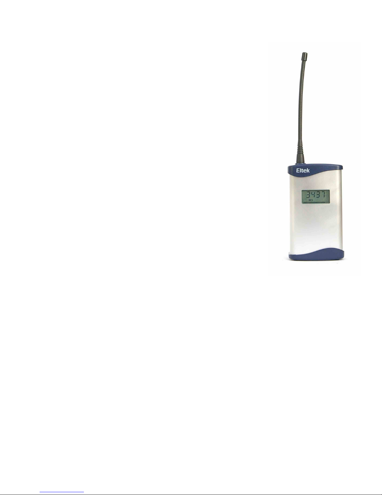
Eltek TU 1004 User Instructions for RC250 receiver
Packed items
"
"
"
"
"
"
"
"
"
"
"
RxConfig software
RxConfig can also be downloaded from: www.eltekdataloggers.co.uk
When installed, RxConfig creates a folder “Eltek”. In this folder are the
RC250 documents for details of Modbus over serial, etc. for Modbus
limitations.
The program allows the user to:-
RC250 receiver with serial and Modbus output
Antenna (basic whip) – Eltek type UHFFlexi/SMA
MP12U5W power supply with regional adaptor
LC68 – RC250 to PC serial lead
USB to serial converter lead
LCTX3 – Transmitter to PC serial lead
RxConfig software
Read transmitter settings
Set the transmitter interval
Associate an RC250 Channel with a specific transmitter channel
Meter configured RC250 channels
Operation
Power Requirements
The RC250 works by first receiving a data 'packet' from a transmitter, verifying it, then
storing it to be read by the external device or PC. It is verified by means of a checksum
contained in the message and the associated transmitter number.
If the RC250 does not receive a message from a transmitter within a configured time, the
stored value will be set to “no data”. For more detail see P6 “No Data interval”.
Example application: Typically data from the RC250 to the PC is updated every 30
minutes, so the transmitter interval is set to 5 minutes (that this PC update period ÷ 6)
and the “No Data” interval to 2 hours. (that is PC update period x 4). If the transmitter
stops transmitting for any reason the PC should register this fact after 2 hours.
The RC250 requires permanent AC mains connection. Use only the AC power supply type
MP12U or the provided MP12U5W. Built-in Ni-Mh batteries provide up to 3 days standby
in the event of power failure. A fully discharged battery is charged in 72 hours. Once the
batteries become low the RC250 will switch itself into a low power mode and turn off the
receiver. will appear in the display.
Note: the RC250 is despatched in the mode.
The RC250 will power up (turn on) next time external power is applied. The display will
then switch to working mode. The RC250 can be turned off by removing the external
power and then clicking > or briefly pressing the concealed
switch accessed through the case rear.
OFF
OFF
Tools Turn Receiver Off
Page 1 of 8
Page 2

Application
Locating the RC250
LED Indicator
RC250 programming leads
File Properties
For users who wish to use the Eltek GenII series of transmitters with third party or
proprietary software. The RC250 can also be used to interface GenII transmitters to an
existing data acquisition system such as the Datataker DT80 using Modbus.
The RC250 and antenna should be located in a position clear of interference, in particular
that generated by computers and monitors, and away from surfaces that can compromise
RF performance e.g. steel or damp or reinforced walls. Use of the optional dipole antenna
will maximise coverage.
A red LED on the top of the RC250 Indicates the receiver has successfully received a valid
data packet.
A single serial port on the PC can be used but this will mean having to change over the
LCTX3 lead and LC68 as required. Note, in > the PC com port can be
nominated. Y
Top panel connections
"
"
LC68 – used to program the RC250 from the PC serial port or via the USB adaptor if
no serial port is available
LCTX3 – used to program the Transmitter from the PC serial port or via the USB
adaptor if no serial port is available
ou can use the in Windows to list the COM ports available
on your computer. Type in the Windows 7 search box to open this, and
look for . USB to serial converters supplied by Eltek are listed as
.
Device Manager
Device Manager
Ports Prolific USB-to-
serial
12V DC
regulated
comms
12VDC
(inner is -ve)
Comms
(6 way mini Din)
Page 2 of 8
Page 3
Using Receiver Config - From V1.1
File
Properties
Menu:
Load the program on your PC – it will try to find an existing Eltek folder. To program the
RC250 use the LC68 lead. Connect one end to the serial port of the PC and the other to
the mini DIN socket situated on the top panel of the RC250. Set the Com port using >
.
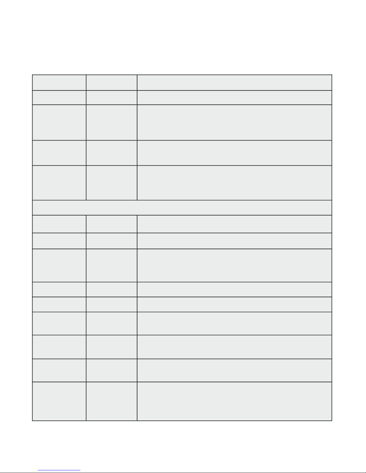
File Load Receiver Upload an existing RC250 configuration
File Save Receiver Save the current RC250 configuration
File Properties Select PC serial port for communications with RC250 and
Transmitter
Tools Turn Receiver
off
Turns receiver off (display indicated OFF)
Tools ModBus
Setup
Sets device (node) address and register addresses for
ModBus communications. See ModBus Configuration
section.
Buttons:
Get TX Get the current configuration from the Transmitter
Set Interval Set TX Interval (use the drop down menu)
Set Sensor On
Time
Applicable only to transmitter where the external sensor
needs power before a reading can be taken. E.g.
GS42/GS44 and GD43
Get RX Get the current configuration from the RC250
Set RX Set the configuration in the RC250
Start Meter /
Stop Meter
Load table with received data
Edit Chan Click over a channel, click Edit Channel to edit. (Use to
accept a transmitter not available for direct connection.)
Clear Chan
data
Click over a channel, click Clear Channel data
Set Nbr Chans Enter Number of channels to display (160 maximum) and
click to confirm (this reduces unnecessary
on screen information and speeds up the interface).
Set Nbr Chans
Page 3 of 8
Page 4

Channel Set-up Procedure
Transmitter present:
* To gain access to the transmitter programming socket the bottom cover must be
removed (2 x pozi-drive screws). Carefully remove the battery pack but do not
disconnect it. The programming socket is a 3mm stereo jack socket that will now be
accessible.
Pulse count transmitters use an internal counter which counts from 0 to 65535 and is
incremented each time a pulse is measured. The counter rolls over when it reaches
65535. Transmitters will send the current value of their internal counter each time they
transmit. It is therefore necessary to perform a calculation in the receiving software /
device which subtracts the previously received pulse counter value from the current
one, giving the number of pulses counted.
"
"
"
"
"
"
"
"
"
"
"
"
"
"
"
Using pulse count transmitters
Start up the Configuration program. (If this is the first time it has run you will need
to configure the serial port(s) using > .)
Connect the PC to the RC250 using the LC68 programming lead (and USB
converter if required)
Get the current or start a new RC250 Configuration using the button ( you
should see the details appear in the right hand list box).
Now connect each transmitter to the PC using an LC-TX3 programming lead.
Use > to set the TX serial port.
Get the transmitter details using the Get TX button (the TX serial number will
appear)
Set the transmitter interval. This should be about one sixth of the update interval
required in the PC (or connected monitoring device)
Click on a channel, click , and choose input type from drop down.
Click to confirm.
Repeat for channels applicable to connected TX
Repeat if a number of transmitters are being added to the RC250
Connect the PC to the RC250 using the LC68 programming lead
Select the destination RC250 channel (by single clicking and highlighting it)
Select the required transmitter channel (by single clicking and highlighting it).
Copy the channel details to the RC250 configuration using the button. Note
RXconfig will assume the next TX channel and next RX channel are to be linked.
Click the button to confirm or set up as required.
Copy the configuration to the RC250 using the Button.
File Properties
Get RX
File Properties
Select Range
OK
>>
>>
Set RX
*
Page 4 of 8
Page 5
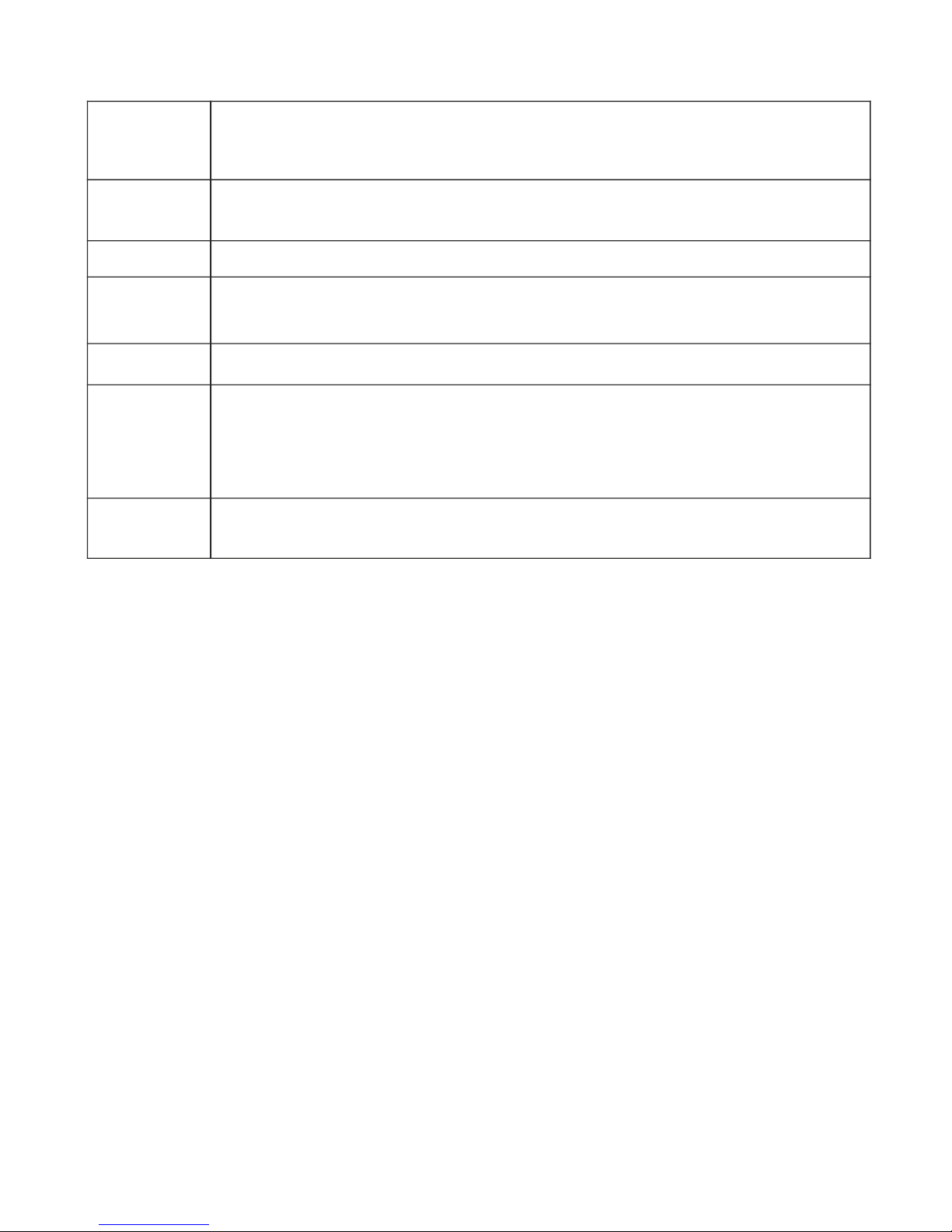
Chan This is the RX250 channel allocated (1 - 160 max)
Tx Chan This is the TX channel allocation and is always an alpha character typically A
to H
Tx Range TX Chan range e.g. Humidity SHT if the B channel of a GD10
Value Tx Value of last valid data received expressed in units allocated to the range.
These can be default or configured as engineering units.
Batt TX battery condition expressed in %
Age Time, in seconds since last valid value received. Value will not be normally
greater than 2 x TX interval. If greater than 2 x TX interval this can indicate
permanent or temporary loss of communications and should be
investigated.
Nbr TX Is the number of successful transmissions received, indicating reliability of
performance and is for statistical purposes only.
Columns in the RX Configuration panel table:
No Data Interval
Within the Edit RX channel is the feature .
The RC250 expects new channel information from the transmitter on a frequent basis to
refresh the last valid value held in a buffer. If data is not received
, e.g. due to transmitter failure, the value is reported as . This in turn can be
processed as appropriate to the application by the connected software.
The No data Interval will default to the TX interval x 6 and can be set (as hh.mm.ss) for
special applications on a per channel basis.
No data Interval
No Data
within a configurable
period
Page 5 of 8
Page 6

Modbus configuration
The ModBus Setup menu allows the configuration of the ModBus node address and
channel registers. Node Address should be set to the required 'Slave ID'. The following six
boxes are for specifying addresses of holding registers for reporting the transmitter
information. The value in each of these boxes must be greater than that in the previous
box. Note the both the 'Reg' address boxes (Raw and Scaled) are only the start addresses
for those registers, and gaps must be left after each of at least the number of channels
configured in the RC250.
Field Description
Node Address ModBus slave ID
Raw Reg Address Base address of Holding Registers for raw value from the sensor
Scaled Reg
Address
Base address of Holding Registers for range-scaled value from the
sensor
Scaling Address Address of Holding Register for scaling factor
Battery Address Address of Holding Register with the most recent battery level
Nbr Tx Address Address of Holding Register containing transmitter serial number
Age Address Base address of Holding Registers containing age of each value.
When reading the values from the RC250, the only Function Code that can be used is 'Read
Holding Registers' (0x03). The registers containing the data start at the respective ‘Base
Addresses' described above. When reading channel values, it is possible to read several at a
time using the 'Quantity of Registers' field, but note that RC250 is limited to 50 registers at a
time.
There was a convention that is still sometimes used with ModBus which refers to the
Holding Registers in the form 4xxxx. With this scheme, what is referred to as 'Holding
Register 40001' is actually addressed within the protocol as register address 0000 - not
register address 0001. We always use the actual register address number that is encoded in
the Modbus message (in this case 0000), and we do not use the '4xxxx' prefix. Occasionally
you may come accross other manufacturer's systems that do not even correctly handle this
offset of 1.
Example request to retrieve holding register 100 (set up to contain the raw value from
channel 1) from node address 6:
Slave Address 06
Function 03
Starting Address Hi 00
Starting Address Lo 64
No. of Registers Hi 00
No. of Registers Lo 01
Page 6 of 8
Page 7

Page 7 of 8
Example response from RC250:
Slave Address 06
Function 03
Byte count 02
Raw Val Hi 06
Raw Val Lo 2b (in decimal, 1579)
CRC Hi 4e
CRC Lo 3b
Example request to retrieve holding register 200-201 (set up to contain the scaled values
from channels 1 and 2) from node address 6:
Slave Address 06
Function 03
Starting Address Hi 00
Starting Address Lo c8
No. of Registers Hi 00
No. of Registers Lo 02
Example response from RC250:
Slave Address 06
Function 03
Byte count 04 (2 readings, so 4 bytes)
Raw Val Hi 00
Raw Val Lo e6 (in decimal, 230 - meaning 23.0 degrees)
Raw Val Hi 01
Raw Val Lo ed (in decimal, 493 - meaning 49.3 %RH)
CRC Hi ac
CRC Lo d9
Raw Reg Address Values, other than pulse counts, contain values less than 65000.
Numbers starting from 65441 (0xFFA1) are used to represent out of range or fault
conditions. These numbers are:
65441 (0xFFA1) - Value is above maximum value of range
65442 (0xFFA2) - Value is below minimum value of range
65444 (0xFFA4) - Sensor is open circuit
65531 (0xFFFB) - No Data
65532 (0xFFFC) - Dummy
Scaled Reg Address Values use the scaling address to represent these same conditions.
The scaling address field, for normal values, would contain a scaling factor of 0 to 4.
Values from 240 (0xF0) upwards contain the following error conditions:
240 (0xF0) - Value is above maximum value of range
241 (0xF1) - Value is below minimum value of range
242 (0xF2) - Sensor is open circuit
243 (0xF3) - No Data
244 (0xF4) - Dummy
Page 8

Product Specification
Maximum no. Channels 160
AC supply 100 to 250V AC (Use only Eltek power supply type
MP12U / MP12U5W)
DC input 12VDC Maximum current <150mA
Battery endurance Up to 72 hours
Controls Concealed button (power off)
Freq. UHF (Europe) Default is 434.225Mhz (the label on the base will give
the exact frequency)
Freq. US Default is 914.5Mhz
Rx sensitivity -117dbm (typical)
Antenna connection SMA socket
Antenna – standard ¼ wave whip (shipped with product) – Eltek type
(supplied)_ UHFFlexi/SMA
Antenna – lightweight dipole Indoor/outdoor dipole, lead length 5m standard,
(optional) accessory type LW-ANT/SMA. The maximum
recommended lead length is 10m.
Antenna – compact Yagi Lightweight 3 element Yagi, providing up to 6db gain
(optional) supplied with 5m lead and plug.
Temperature Range -10 to +55ºC
Humidity 95% non condensing
Environment Indoor use only IP40. A secondary enclosure must be
used for outdoor use
Transmitter types All in GenII range from serial number 7000
Transmitter Interval 1 second to 4 hours
TU1004GB 14/11/13
Page 8 of 8
Serial Data
Both ModBus and RC250 Serial Interface protocols are implemented on an RS232
interface. The interface requires no configuration and will automatically respond
appropriately to either protocol. It is preset to these settings:
Baud Rate 19200
Data Bits 8
Stop Bits 1
Parity None
 Loading...