

Eltek Smartpack2 User Manual
350020.013
Monitoring and Control Units
Powerpack, Flatpack2 & Minipack
DC Power Supply Systems
User's Guide
Smartpack2 Master Controller
1 Introduction
2 User's Guide Smartpack2 Master Controller 350020.013, Issue 2.0, 2014 Jan
DC Power Supply Systems
SAFETY and ENVIRONMENTAL PRECAUTIONS
The product warranty becomes invalid if the following safety precautions are not followed during handling,
installation, commissioning and general use/operation of Eltek DC power supply system.
General Precautions
CAUTION: Even though the product incorporates protection circuitry and other safeguards, it can be damaged, perform
poorly or have a reduced lifetime if it is exposed to incorrect treatment during transport, installation or service.
Always handle the equipment using proper lifting techniques, do not roll, climb or drill hole in the cabinets or enclosures.
WARNING: Opening the equipment may cause terminal injury — even if the mains AC supply is disconnected.
Hazardous voltages may be present inside, as large capacitors may still be charged.
Device
Hazard
!
Electric
Shock
G1
G2
Environmental Precautions
CAUTION: To avoid damage the equipment, keep objects clear of system ventilation inlets, outlets and system fans,
if any, ensuring the airflow through the units is not obstructed, and that the fans rotate freely. Use caution with rectifiers,
as they can reach extreme temperatures under load and normal operation.
WARNING: The installer/user is responsible for ensuring that the DC power system is not damaged by current
surges, over-voltages, etc. caused by external transients, lightning, electrostatic discharge, etc. To avoid damage
and obtain the expected system reliability, it is mandatory to always install SPDs in Eltek’s power supply systems.
Follow the instructions given in “Guidelines for Lightning and Surge Protection”, doc. 2024623.
WARNING: The electronics in the power supply system are designed for indoor, clean environment. When
installed in outdoor enclosures, it is important to keep the door closed during operation, and replace the filters on a
regular basis. Indoor installations in dusty or humid areas require appropriate air filtering of the room, or
filtering of the air entering the DC power system. Follow the instructions given in “Generic Guidelines
Environmental Protection.”, doc. 2038879.
Ventilated
Hot Surface
Humidity & Dust
Protection
Current Surge
Protection
E2
E1
E3
CAUTION: This product is tested and verified according to international safety, environmental and EMC standards. Any
non-Eltek equipment installed into this product after delivery might influence the performance and could infringe the
original approvals. The installer is responsible for ensuring that the environmental properties of this product/ system do
not deteriorate during installation, and that it is performed in accordance with applying regulations.
Installations in USA and Canada must comply with NEC/CEC requirements.
Precautions during Installation
CAUTION: Read the user documentation carefully before installing and using the equipment, as installation and
operation is to be performed as described in it. Always tighten screws and bolts with the torque values recommended in
the documentation. For safety reasons, the commissioning and configuration of the equipment is only to be performed
by Eltek’s personnel or by authorized and qualified persons.
CAUTION: Before you start the electrical installation, you must always disconnect all external AC supply fuses, as well
as internal battery and load fuses/ breakers, if any.
WARNING: For safety reasons (high leakage current / high touch current) you must always connect the AC earth
wire (PE) to the terminals, before you connect the AC input cable(s).
The batteries, if any, represent a major energy hazard. To avoid short-circuit of battery poles, you must always
remove metallic objects — uninsulated tools, rings, watches, etc. — from the vicinity of the batteries.
WARNING: 60V and higher DC power systems are only to be installed in Restricted Access Locations (RAL).
Access must be limited by use of tool, i.e. lock and key.
Device
Hazard
!
Qualified
Personnel
!
EMC, NEC/CEC
Regard
!
Electric
Shock
Electric
Shock
I1
I2
I3
I4
I5
356800.183, 3v3

1 Introduction
User's Guide Smartpack2 Master Controller 350020.013, Issue 2.0, 2014 Jan 3
Part number for Smartpack2 Master Controller: 242100.500
350020.013 Issue 2.0, 2014 Jan
Published 2014-03-06
mafeno

1 Introduction
4 User's Guide Smartpack2 Master Controller 350020.013, Issue 2.0, 2014 Jan
Table of Contents
1. Introduction ................................................................................. 5
About this Guide ............................................................................................... 5
System Diagram — Flatpack2 Power System w/SP2....................................... 5
2. The Smartpack2 Master Controller ............................................ 6
Key Features .................................................................................................... 6
Location of Connector, Communication Ports .......................................... 7
Opening and Closing Smartpack2 Master Controller ............................................... 7
CAN Bus Termination ....................................................................................... 8
CAN Bus Cabling ...................................................................................................... 8
Front Panel Operation ................................................................................. 9
Graphical Display .............................................................................................. 9
Front Keys ........................................................................................................ 9
Software Menus .............................................................................................. 10
Controller Access — Via Stand-alone PC ................................................ 11
Technical Specifications ........................................................................... 12
..................................................................................... 12
Firmware Upgrade Controller .................................................................... 13
Firmware Upgrade from the SD Card ..................................................................... 13
Firmware Upgrade from a Computer ...................................................................... 14
Overview LAN Devices and Firmware Files (PC - S19 Format)........................ 14
3. About Power System Configuration ........................................ 15
Logical Groups or Menu Options .................................................................... 15
1 - System Status options ....................................................................................... 16
2 - System Configuration options ............................................................................ 16
3 - Alarm Configuration options .............................................................................. 16
4 - Commands options ............................................................................................ 17
5 - Logs and Reports options .................................................................................. 18
6 - Statistics options ................................................................................................ 19
7 - Commissioning options ..................................................................................... 20
8 - Up/Download options (Data Storage Device) .................................................... 20
SD Card Storage - Overview Firmware Files (Binary Format) .......................... 21
Flash Memory Storage ...................................................................................... 22
Alarm Monitors ................................................................................................ 23
Types of Alarm Monitors ......................................................................................... 25
Typical Parameters for Alarm Monitors .................................................................. 26
Alarm Output Groups ...................................................................................... 28
Output Test Commands .................................................................................. 31
Alarm Outputs Isolation (Output Blocked) ...................................................... 31
1 Introduction
User's Guide Smartpack2 Master Controller 350020.013, Issue 2.0, 2014 Jan 5
1. Introduction
The advanced Smartpack2 Master controllers are developed for Eltek’s Flatpack2 DC
power systems that implement the Smartpack2-based distributed control system.
About this Guide
This booklet provides users of Smartpack2-based DC power systems with the required
information for operating the system using the Smartpack2 Master’s front panel. The
booklet also describes the Smartpack2 Master controller’s building blocks, external
connections and technical specifications.
Read also the generic and site specific documentation for your DC power system.
For detailed functionality description, browse and search through the Functionality
Description topic in PowerSuite Online Help or CWUI Online Help. Notice that you must
log in to access Online Help (contact your Eltek representative)
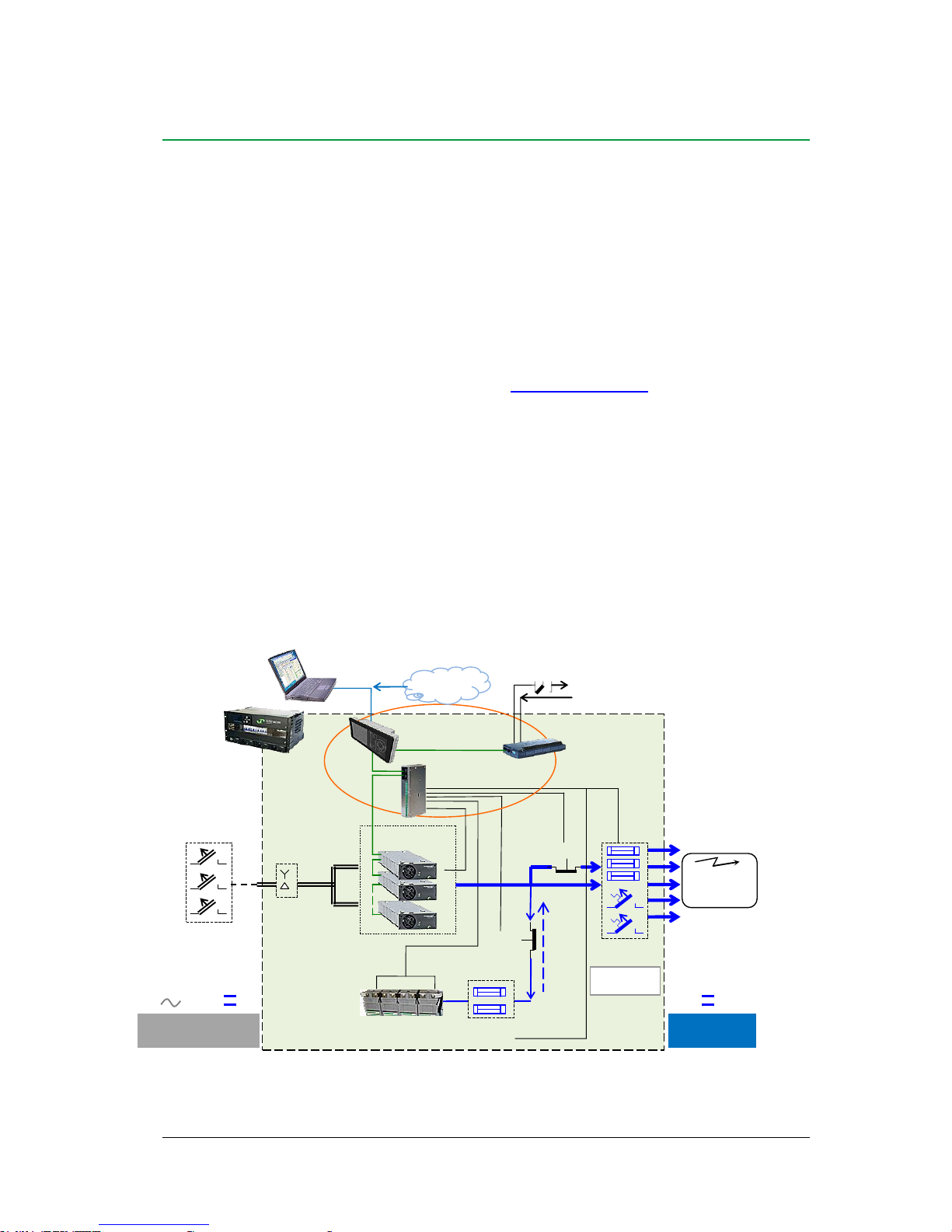
System Diagram — Flatpack2 Power System w/SP2
The generic Smartpack2 (SP2) distributed control system — used in Flatpack2 PS systems
— monitors and controls the whole system, and consists of the Smartpack2 Master (SP2M)
controller, the Smartpack2 Basic (SP2B) controller and the I/O Monitor2 CAN node.
The Smartpack2 Master serves as the local user interface between you and the system. The
system may also be configured via the Controller’s Web-based User Interface (CWUI) on
a standard web browser, and via the PowerSuite PC application. The Smartpack2 Basic
monitors and controls the power system’s internal wiring and supplies the CAN bus with
power. The I/O Monitor2 CAN node implements input and output signals.
Figure 1 Typical Flatpack2 DC power system for telecom and industrial equipment, fed from external AC mains or
DC supply. It consists of rectifiers in power shelves, master and basic controllers, DC distribution, etc.
Battery string #1
AC mains
supply
selector
Temp.
Sensors
LVLD
LVBD
Fuse Alarm
AC Fuses, external
(230VAC or 400VAC
or 85-300VDC)
Battery
Fuses
Load Fuses
& MCBs
Flatpack2 HE
rectifiers
CAN Bus
DC
Distribution
DC Output
(24V, 48V
or 60V)
Flatpack2
System
Ethernet
cable
Internet
Telecom and
Industrial
equipment
Smartpack2
Master Controller
Smartpack2
Basic Controller
Alarm Outputs NC-C-NO
Config. Inputs
CWUI
(Controller’s web-
based user interface)
I/O Monitor2
CAN node
AC Input
(Single- or 3-phase
or DC Input)
OR
2 The Smartpack2 Master Controller
6 User's Guide Smartpack2 Master Controller 350020.013, Issue 2.0, 2014 Jan
2. The Smartpack2 Master Controller
The Smartpack2 Master controllers are powerful modules used as master controllers in the
distributed control system of Smartpack2-based power supply systems. They serve as the
local user interface between you and the power system.
The Smartpack2 Master controller is 2U high and 160mm wide, and it is mounted in the
power system’s front panel or door. The CAN bus is the only connection between the
Smartpack2 Master and the Smartpack2 Basic controller, which provides great installation
flexibility.
Key Features
A wide range of features are implemented in the Smartpack2 Master controller, as
mentioned below:
Graphical TFT high contrast, high resolution color display for easy navigation
LEDs for local visual alarming (Major, Minor, Power ON)
Ethernet for remote or local monitoring and control via WEB Browser
Ethernet port for straight-through and crossover cables
SNMP protocol with TRAP, SET and GET on Ethernet. Email of TRAP alarms
Comprehensive logging
Automatic battery monitoring and test
Battery lifetime indication
Battery used and remaining capacity (Ah or %) monitoring
User defined alarm grouping (Boolean logic for grouped alarms)
Uploading and downloading of firmware and configuration files with SD card
SD card slot for downloading/uploading of logs and setup
Comprehensive generator/hybrid/DC solar system control and monitoring features
Read also chapter “Technical Specifications”, page 12, for more details.

2 The Smartpack2 Master Controller
User's Guide Smartpack2 Master Controller 350020.013, Issue 2.0, 2014 Jan 7
Location of Connector, Communication Ports
Figure 2 Location of CAN ports and Ethernet connector in the Smartpack2 Master controller
CAN port 1 and 2 are electrically identical, and are used to enable connection of the CAN
bus incoming and outgoing CAT5 cables, or the RJ45 CAN bus termination plug.
Opening and Closing Smartpack2 Master Controller
Opening the controller’s right side enables inserting an SD card and temporarily
connecting an Ethernet cable.
1. To open it,
pull the handle’s knob slightly outwards
(use your fingers or a pen) and
2. then slide the handle to the left
(the controller’s right side opens)
3. To close it,
slide the handle to the right (the controller's
right hand side closes, almost), then push the
controller's front inwards, to close it
completely
Ethernet
cable
Smartpack2
Master Controller
CWUI
(Controller’s webbased user interface)
(Ethernet cable
Standard straight through cable
OR crossover cable)
Smartpack2 Master
controller (open)
Handle in open
position
SD card
RJ-45 socket
for Ethernet connection
CAN port 1&2
Electrically identical
(CAN bus
(twisted-pair CAT5 cable)
RJ-45 socket
for Ethernet connection
Smartpack2 Master
controller (locked)
Handle in locked position
Smartpack2 Master
controller (open)
Handle in open
position
SD card

2 The Smartpack2 Master Controller
8 User's Guide Smartpack2 Master Controller 350020.013, Issue 2.0, 2014 Jan
CAN Bus Termination
To ensure a correct bus communication and avoid data reflection, you must always
terminate the CAN bus with two 120 resistors, one at each end of the line (60 bus
impedance).
Smartpack2-based DC power systems are shipped from factory with the CAN bus already
terminated with 120 resistors. The CAN bus termination is implemented with a special
RJ45 plug with built-in 120 end-of-line resistor.
Figure 3 Example of CAN bus addressing and termination in a Flatpack2 power system with
Smartpack2-based control system and several monitors connected the CAN bus
When connecting more CAN nodes to the bus, you have to remove the CAN bus
termination plug from one of the CAN bus ends, and plug it in one of the CAN ports on the
last connected CAN node.
CAN Bus Cabling
In addition to the two dedicated wires for communication, the CAN bus multi-wire cable
must integrate wires for the CAN power supply and other signals. In standard industrial
environments, the CAN bus can use standard cabling without shielding or twisted pair
wiring. If very low interference (EMI) is required, a CAT-5 twisted-pair cable is
recommended.
Flatpack2
DC Power System
CAN bus
(twisted-pair
CAT5 cable)
33
Battery string #1
Battery Monitor
ID Number
I/O Monitor2
81
Load Monitor
49
End-of-Line
Resistor
120
Fuses
Fuse Monitoring
Configurable Inputs
Current Monitoring
Sense Inputs
Shunts
Alarm Outputs NC-C-NO
Config. Inputs
End-of-Line
Resistor
120
Smartpack2
Basic Controller
Flatpack2 HE
Rectifiers
01
02 n 1
Internal System Monitoring
Smartpack2
Master Controller
Ethernet cable (LAN)
CWUI
(Controller’s web-based user interface)
I/O Monitor
82
Alarm Outputs NC-C-NO
Config. Inputs
Temp, Fan Speed Mon & Ctrl

2 The Smartpack2 Master Controller
User's Guide Smartpack2 Master Controller 350020.013, Issue 2.0, 2014 Jan 9
Front Panel Operation
This chapter describes the Smartpack2 Master controller’s keys and indicators, and how to
operate the Smartpack2-based DC power system from the controller’s front panel.
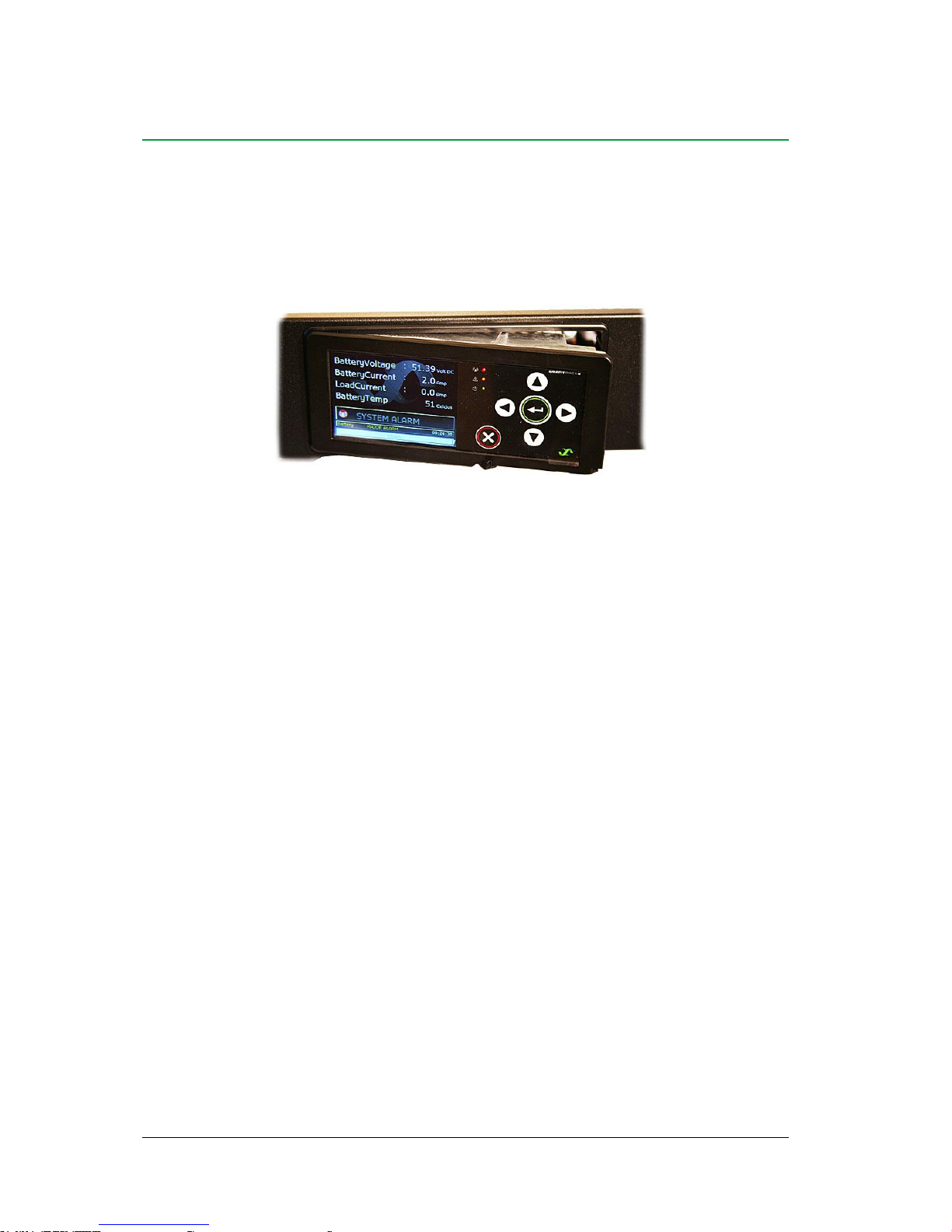
Figure 4 Smartpack2 Master controller’s front keys and indicators
Graphical Display
The Graphical Color Display — 3.2” TFT 32k, QVGA 320x240 — is either in Status
Mode (displays the system’s status) or in Menu Mode (displays the menu structure).
The Smartpack2 Master controller has the following LED indications:
Table 1 Description of the Smartpack2 Master controller’s LED illumination status
Front Keys
You can operate the power system navigating intuitively through the graphical menu
structure via the following 6 front keys.
Press on the key
to change from Status Mode to Menu Mode and to select options, enter values
Press the key
to navigate to previous level and cancel options and values
Press the
or
keys
to navigate up- or downwards, point at options and increase and decrease values
Press the
or
keys
to navigate one page up- or downwards and point at options
Smartpack2 Master controller
Handle in locked position
”Enter” key
“Cancel” key
Arrow keys
”Alarm” LED lamp (red)
“Warning” LED lamp (yellow)
“Power” LED lamp (green)
Graphical Color
Display
3.2” TFT 32k, QGVA
320x240
LED
Indicator
Illumination
Status
Description
Power
OFF
ON green
Flashing Green
The controller has NO supply
Supply healthy
Distributed Power Fault
Warning
OFF
ON amber
Flashing amber
No Warning
Warning (Minor alarm, non-critical alarm)
Communications Fault
Alarm
OFF
ON red
Flashing red
No Alarm
Alarm (Major Alarm, critical alarm)
SW Fault / Boot Loader Mode
2 The Smartpack2 Master Controller
10 User's Guide Smartpack2 Master Controller 350020.013, Issue 2.0, 2014 Jan
Software Menus
The Smartpack2-based system’s functionality is accessed via a network of software menus
and submenus, enabling you to configure and control the whole power system from the
controller’s front panel. When browsing the menus, the Menu Level Indicator shows the
menu level you are in. Editing parameters is password protected, (default pin code <0003>
may be changed for security reasons). The display can be in Status Mode or in Menu Mode.
From a PC’s web browser, or running the PowerSuite program, you can also access the
complete system functionality, described in the programs’ Help and in Online Help.
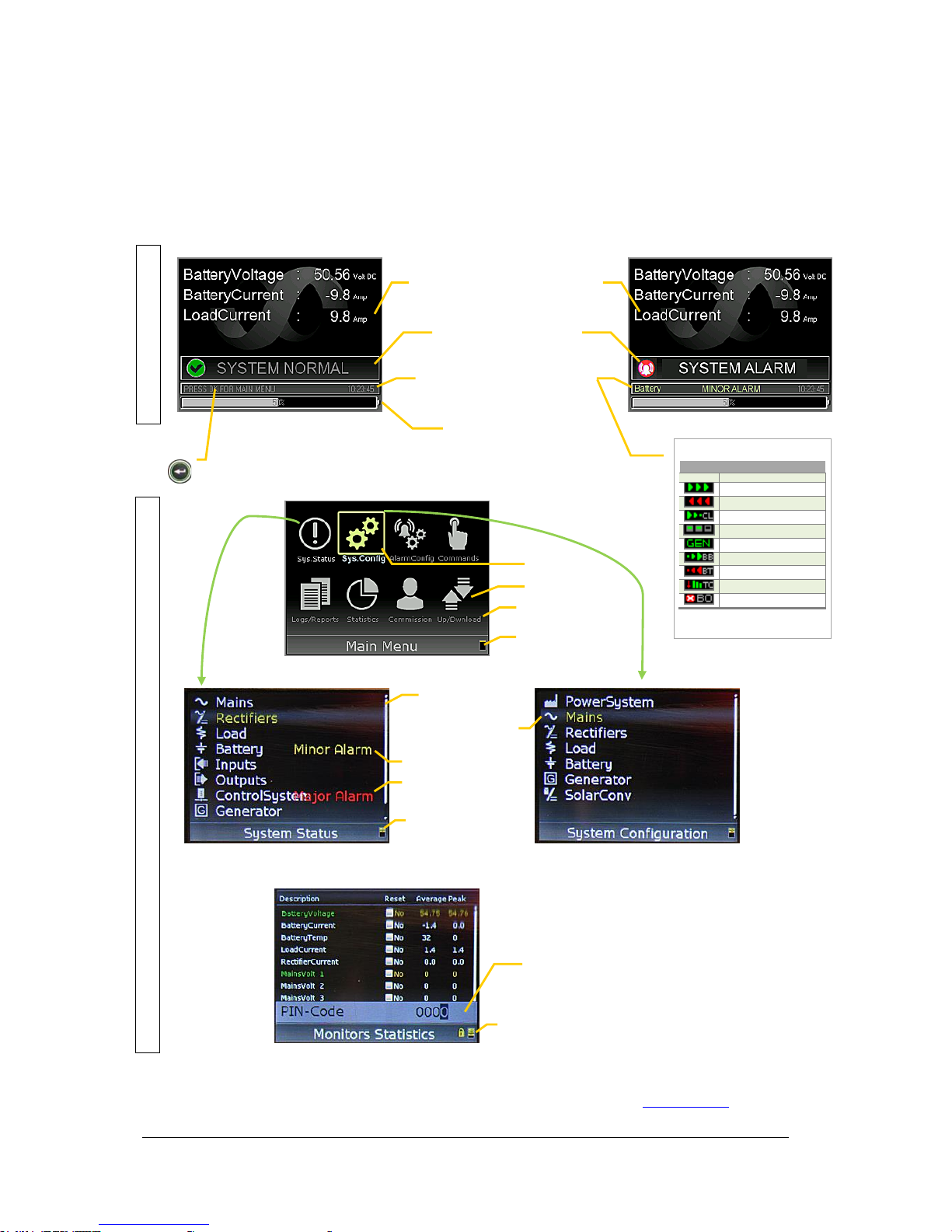
Status Mode
System in Normal Mode
System Parameters
Display more with the → and ← arrow keys.
(Display area P)
System in Alarm Mode
System Status
Normal mode, Alarm mode, etc.
(Display area S)
System Messages
Animated icons, keys to press, alarms,
system time, etc
(Multi-Info field, Display area M)
Status Battery Bank
Displayed in % or in Ah
(Display area B)
Menu Mode
Main Menu Options (Level 1)
Menu Icons
Menu Names
Menu Level Indicator
hierarchical menus (Level 1)
Submenu “System Status” (Level 2)
Submenu “System Configuration” (Level 2)
Scrollbar
Menu Level Indicator
hierarchical menus (Level 2)
Chosen option (yellow text)
Press “Enter” to display the
Mains submenu
Warning (minor alarm)
Alarm (major alarm)
Example Submenu “Monitors Statistics” (Level 3)
Menu Level Indicator
hierarchical menus (Level 3)
Pin Code required for changing configured parameters
(use the ↑ or ↓ arrow keys to enter code).
Default pin code <0003> (should be changed for security reasons)
Chosen option
To change from Status Mode
to Menu Mode press on this
key:
Animated System Messages (M)
in Normal Mode
Icon
Enabled Function
none
Float Batt. Charging
Battery Charging
Battery Discharging
Current Limitation
Efficiency Management
Generator running
Batt. Boost Charging
Battery Test
Temp. Compensated Ch.
Outputs Blocked
When no battery bank installed, the
icons are shown in Display area B
 Loading...