

350003.013
User’s Guide
Monitoring and Control Unit
Flatpack2 DC Power Supply Systems

1 Welcome
2
User’s Guide Smartpack Monitoring & Ctrl Unit,
350003.013, v5-2006-11
Information in this document is subject to change without notice and does not represent
a commitment on the part of Eltek Energy.
No part of this document may be reproduced or transmitted in any form or by any means
— electronic or mechanical, including photocopying and recording — for any purpose
without the explicit written permission of Eltek Energy.
Copyright ©: Eltek Energy, Norway 2006
Certificate no: 900005E
Certificate no: 900005Q
Safety Precautions
The equipment described in this manual must only be operated by
Eltek Energy personnel or by persons who have attended a suitable
Eltek Energy training course
The equipment represents an energy hazard and failure to observe this
could cause terminal injury and invalidate our warranty
There are hazardous voltages inside the power system. As the modules
incorporate large charged capacitors, it is dangerous to work inside the
system even if the mains supply is disconnected
Products into which our components are incorporated have to comply with a
number of requirements. Installation is to be in accordance with the
recommendations herein
Please read the manual carefully before using the equipment
350003.013 Issue 5, 2006 Nov
Published 2006-11-25
Mfm

1 Welcome
User’s Guide Smartpack Monitoring & Ctrl Unit,
350003.013, v5-2006-11
3
Table of Contents
1.
Welcome 5
About this Guide .............................................................................................................5
System Diagram ⎯ Flatpack2 Power System................................................................5
2. The Smartpack Controller 6
Key Features...................................................................................................................6
Block Diagram.......................................................................................................6
Typical Applications........................................................................................................7
Location of Connectors & Communication Ports ..............................................7
System & Battery Signals ⎯ Internal Connections.........................................................8
Alarm Relay & Digital Input Signals ⎯ Customer Connections......................................9
CAN Port Signals ⎯ Internal Connections....................................................................10
CAN bus...............................................................................................................10
CAN bus Addressing.....................................................................................................10
Hardware Assignment ⎯ Controllers .....................................................................10
Software Assignment ⎯ Rectifiers.........................................................................11
CAN bus Termination....................................................................................................11
Firmware Upgrade of the
Smartpack
controller ...............................................12
Module Options...................................................................................................13
Smartpack Controller ⎯ Standard................................................................................13
Smartpack Controller ⎯ Ethernet.................................................................................13
Smartpack Controller ⎯ RS232....................................................................................14
RS232 option Front Access.....................................................................................14
RS232 option Rear Access......................................................................................14
RS232 Port Signals..................................................................................................14
Smartnode Module........................................................................................................15
3. Installation of Smartpack Controller 16
Safety precautions.............................................................................................. 16
Mounting and Removing the Controller............................................................16
Removing Blind Panels.................................................................................................16
4. Front Panel Operation 17
Description of Keys, Display and Indicators.....................................................17
LED indicators...............................................................................................................17
LCD Display..................................................................................................................17
Front Keys.....................................................................................................................17
Modes of Operation.............................................................................................18
Status Mode..................................................................................................................18
Menu Mode...................................................................................................................18
Operating Menus, Overview...............................................................................18
User Options UO........................................................................................................19
Service Options SO...................................................................................................20
5. Technical Specifications 21

1 Welcome
4
User’s Guide Smartpack Monitoring & Ctrl Unit,
350003.013, v5-2006-11
6. Functionality Description 22
Alarm Reset UO (AlarmReset)...................................................................................22
Display System Voltages UO (VoltageInfo) ...............................................................22
Display Alarm Messages, (Log) UO (DisplayMessages)...........................................22
Display Controller’s Firmware Version UO (SoftwareInfo).........................................23
Display Controllers’ Serial Numbers UO (SerialNumber)...........................................23
Display Rectifier Information UO (Rectifier Info)........................................................23
Plug-and-Play Rectifier ...........................................................................................................24
Mains Phase Assignment versus Rectifier ID.........................................................................24
Resetting the Number of Rectifiers.........................................................................................24
Display System Mains Data UO (Mains Info).............................................................25
Display Battery Temperature Levels UO (TempLevel Info) .......................................25
Display Battery Information UO (BatteryInfo).............................................................26
About Battery Banks, Strings and Blocks ...............................................................................26
Battery Symmetry Measurements ⎯ 48V Systems................................................................27
1 Welcome
User’s Guide Smartpack Monitoring & Ctrl Unit,
350003.013, v5-2006-11
5
1. Welcome
The Smartpack controller is a powerful and cost-effective module, developed for
monitoring and controlling a wide range of Eltek’s DC power supply systems, such as
Powerpack, Flatpack2 and Minipack DC power systems.
About this Guide
This booklet provides users of Smartpack-based DC power systems with the required
information for operating the system using the Smartpack’s front panel. The booklet also
describes the Smartpack controller’s building blocks, external connections and technical
specifications.
Read also the generic and site specific documentation that was delivered with your
Smartpack-based DC power system.
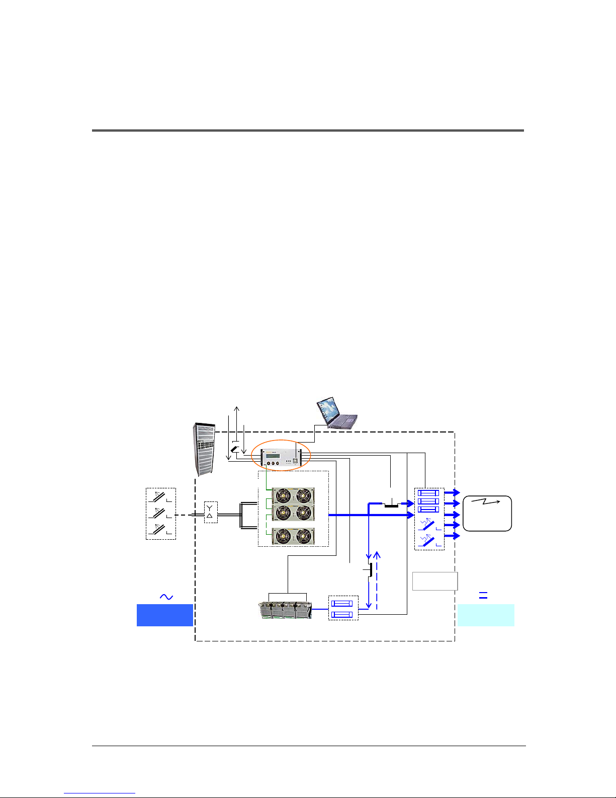
System Diagram ⎯ Flatpack2 Power System
In the Flatpack2 PS system shown in Figure 1, the Smartpack controller monitors and
controls the whole system, and serves as the local user interface between you and the
system. The PowerSuite application is used for remote operation and system
configuration.
Figure 1 Example of a typical Flatpack2 PS system for DC power supply of telecom
equipment. The system is fed from an external AC mains supply, and consists of
rectifiers in power shelves, a control unit and DC distribution unit. Battery banks,
LVD contactors, etc. are typically also a part of the system.
Flatpack2
Cabinetize
d
Battery string #1
A
C mains
supply
selector
Symmetry
Alarm &
Temp. Senso
r
LVLD
LVBD
Fuse Alarm
AC Fuses,
external
(230VAC or
400VAC
Telecom
equipment
AC Supply
(Single- or
three-
p
hase)
A
larm Outputs NC-C-NO
Digital Inputs
Batte
r
y
Fuses
Load Fuses
& MCBs
Smartpack
ctrl. unit
Flatpack
2
rectifiers
PowerSuite
A
pplication
CAN Bus
USB cable
DC
distribution
DC Supply
(24V, 48V
or 60V*
)
*Available from 2007
Remote
Monitorin
g
2 The Smartpack Controller
6
User’s Guide Smartpack Monitoring & Ctrl Unit,
350003.013, v5-2006-11
2. The Smartpack Controller
The Smartpack controller is a monitoring and control unit used as the vital nerve center
of the DC power plant. You operate the system from the elegant front panel, using three
front keys and the LCD-display. They represent the main interface between you and the
system.
You can also operate the system locally via a PC using Eltek’s PowerSuite application, or
remotely via modem, Ethernet and the Web. The module then utilizes the USB- or RS232 ports to interface with a local PC, SNMP or Web adapters. See also chapter
“Technical Specifications”, on page 21.
Key Features
Front panel LCD and buttons for on-site service without PC.
USB- or RS-232 interface for PC connection locally or remote monitoring
and control via modem, Ethernet, web or SNMP.
Main program upgrade via USB port and the FWLoader application
6 user programmable relay outputs for traditional remote control
6 user programmable inputs for monitoring of other equipment on site
Battery monitoring and testing without site attendance
Temperature compensated charging for increased battery lifet ime
Battery lifetime indication
Password protected operator access levels
Alarm/event log with time and date
Windows-based PC communication software
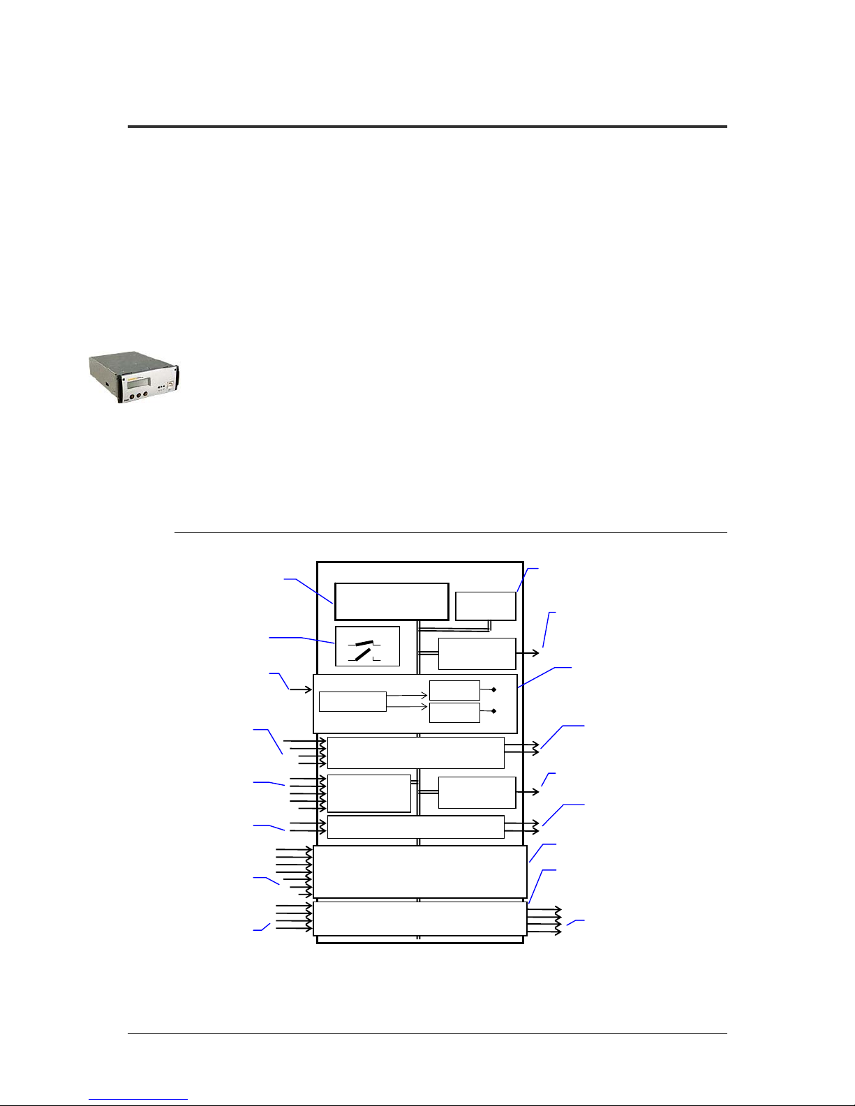
Block Diagram
Figure 2 Block diagram of the Smartpack Battery Extended controller showing the module’s
main functions
Smartpack Controller
Microprocessor
FLASH & EEPROM Memory
256Kb
EEPROM
512Kb
CAN1
Power Bus
The microprocessor is the heart of
the system and represents the
intelligence in Smartpack controller.
The main program and dynamic
data are stored in Flash memory
chips, easily upgraded via the USB
or CAN ports
CANport (2)
for communication with rectifiers and
other controllers on the CAN bus
DIP switches for
configuring the controller’s
CAN bus ID numbe
r
24 / 48 / 60VDC Input supply
Power supply
with regulated supply voltages
for internal and external use
(plug-in PCB)
A
ll customer-specified functions,
calibration and log data are stored in
EEPROM chips
DIP switch
Power supply
Flyback rectifier
Step Down
Reg.+5V
Step Down
Reg. ±12V
CON5
System Connections (internal)
Inputs signals
(measurements)
for system reference(1),
battery current, battery &
load fuse fail (3)
Output signals (control)
for LVD latching relays (2)
CON4
Battery Connections
(internal)
Inputs signals
(measurements) for battery
symmetry (4), temperature
sense (1)
CON1
Alarm I/O Connections (customer)
Inputs signals
(measurements) for con-
figurable digital inputs (2)
Output signals (control)
for Alarm relays (2)
CON3
Battery Connections (internal)
Inputs signals
(measurements) for battery
symmetry (4), temperature
sense (1), battery current
(1), battery fuse fail (1)
CON2
Alarm I/O Connections (customer)
Output signals (control)
for Alarm relays (4)
(
Plug-in PCB)
(
Plug-in PCB)
Inputs signals
(measurements) for con-
figurable digital inputs (4)
USB
Serial Bus
USB 2.0 type B port (1)
serial communication interface with
PCs and computer devices
2 The Smartpack Controller
User’s Guide Smartpack Monitoring & Ctrl Unit,
350003.013, v5-2006-11
7
Typical Applications
The Smartpack controller employs CAN bus communication with the rectifiers in the
Smartpack-based DC power system ⎯ and other bus-connected Smartpack controllers in
the system ⎯ thus enabling flexible expansion of system functionality and number of
measuring points. System components can be set up and upgraded to meet the demand
of any tailor-made power solution.
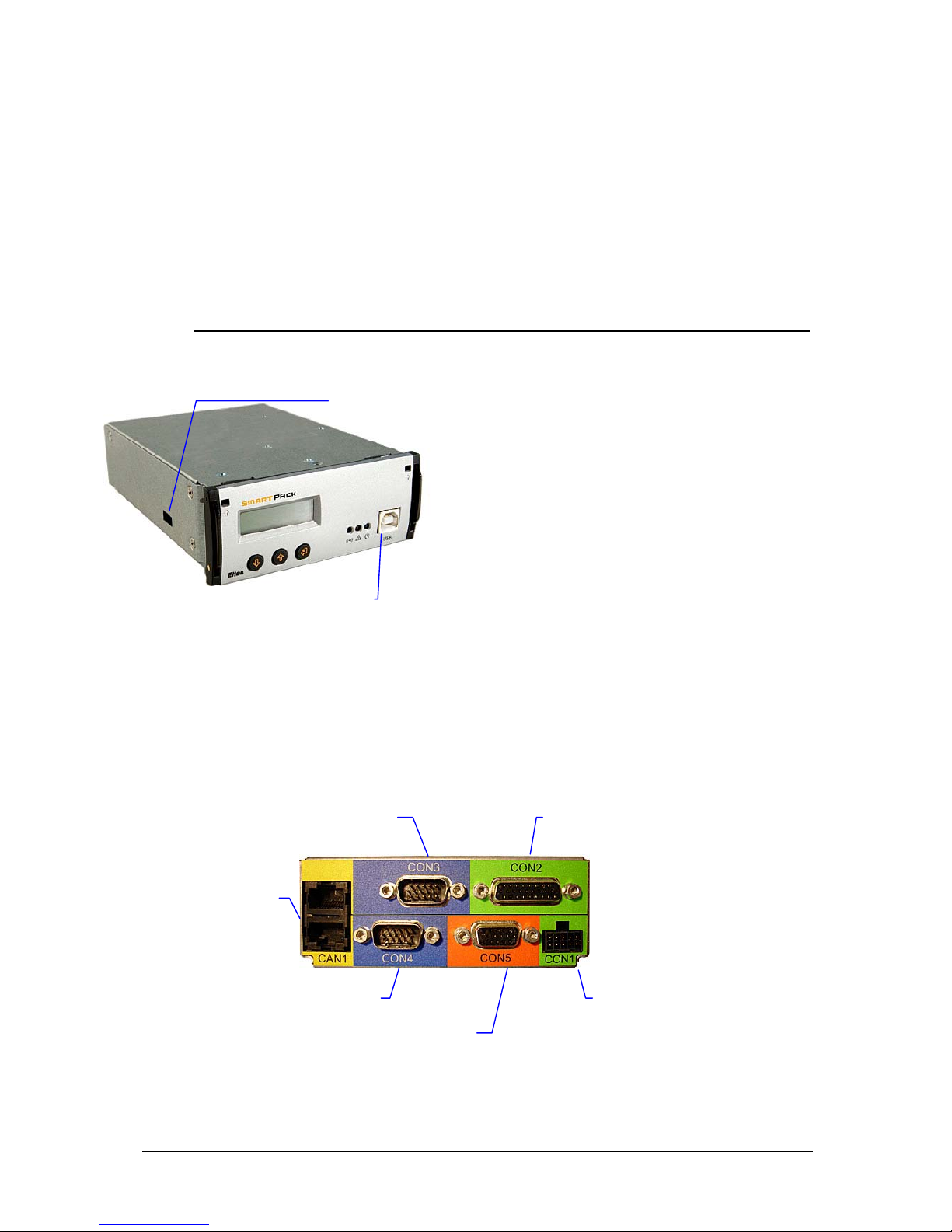
Location of Connectors & Communication Ports
You can easily connect the Smartpack
controller to a PC, plugging a standard USB
A-B cable to the USB port on the front of the
controller and to any available USB port on
the computer.
The Smartpack controller is configured from
factory ⎯ via DIP switches on the side ⎯ with
an ID number for CAN bus communication.
On the controller’s rear panel ⎯see Figure 4
⎯ you find two identical RJ45 CAN ports (for
incoming and outgoing CAT5 twisted-pair
cables) to connect the controller to the CAN
bus. See also chapter “CAN bus”, on page 10.
Figure 3 Front access USB port, and DIP switches for ID configuration on the side.
The Smartpack controller’s system cable connections are located on the controller’s rear
panel. These connections are used for monitoring and controlling the system, the
batteries, alarm relays and status of external equipment.
Figure 4 Rear plug connections on a Smartpack Battery Extended controller
USB 2.0 type B port
(PC connection)
DIP switches
(CAN ID number)
A
larm I/0 Connections ⎯ Extended
D-sub, 26 pins, female (Customer)
CAN port (2)
RJ45, 8 pins connecto
r
(Internal and customer)
Battery Connections ⎯ Extended
D-sub, 15 pins, male (Internal)
Battery Connections
D-sub, 15 pins, male (Internal)
System Connections
D-sub, 15 pins, female (Internal)
A
larm I/0 Connections
Mini power connector,
10 pins, male (Customer)

2 The Smartpack Controller
8
User’s Guide Smartpack Monitoring & Ctrl Unit,
350003.013, v5-2006-11
System & Battery Signals ⎯ Internal Connections
In standard Smartpack-based DC power systems, the
controller’s internal signals are cabled either directly to
the corresponding monitoring or measuring points, or
to internal terminals, as shown in Figure 5. See your
system’s specific arrangement drawings.
Figure 5 Overview of internal system and battery connections
System Specific Interface Terminals
+
−+−+−+−+−
+/
−
+/
−+/−
10
15
14
4
5
6
7
12
13
9
11
1
3
2
Power Input
Batt. Fuse Fail 1
Load Fuse Fail 1
System Voltage
System Reference
Batt. Current 1
(Internal Connections)
LVD1A
LVD Common
LVD2A
LVD1*
LVD2*
Out
In
* To latching relays.
15-pins
D-Sub
male
Interface
Cable 5
Notice: the signals available at the
interface terminals may vary. Read
your system’s specific documents.
System
Connections
CON5
15 pins D-Sub (female)
LVD1A +/− 1
LVD2A +/− 2
LVD Common +/− 3
System Voltage + 4
System Voltage − 5
a
*Batt Current 1 + 6
b
*Batt Current 1 − 7
NC 8
Load Fuse Fail 1 + 9
Power Input + 10
Load Fuse Fail 1 − 11
c
*Batt Fuse Fail 1 + 12
d
*Batt Fuse Fail 1 − 13
System Reference 14
Power Input − 15
FUNCTION SIGNAL PIN-OUT
5 1
15 11
CON5
(female; orange)
Smartpack
controller
15-pins
D-Sub
female
Interface
Cable 4
+
−
+
−
+
−
+
−
+
−
3
1
6
5
11
10
15
13
4
2
7
8
14
12
Batt. Symmetry 1
Temp. Sense 1
NC a*, b*
NC
c
*, d*
Batt. Symmetry 3
Batt. Symmetry 2
Batt. Symmetry 4
Internal
Connections)
In
System Specific Interface Terminals
FUNCTION SIGNALPIN-OUT
CON4
15 pins D-Sub (male)
Batt Sym 1
−
1
Temp Sense 1 − 2
Batt Sym 1 + 3
Temp Sense 1 + 4
Batt Sym 2 − 5
Batt Sym 2 + 6
a
* NC 7
b
* NC 8
NC 9
Batt Sym 3 − 10
Batt Sym 3 + 11
d
* NC 12
Batt Sym 4 − 13
c
* NC 14
Batt Sym 4 + 15
Battery
Connections
1 5
11 15
CON4
(male; blue)
Smartpack
controller
15-pins
D-Sub
female
Interface
Cable 3
System Specific Interface Terminals
+
−
+
−
+
−
+
−
+
−
+
−
+
−
3
1
6
5
11
10
15
13
4
2
7
8
14
12
Batt. Symmetry 5
Temp. Sense 2
Batt Current 2
Batt Fuse Fail 2
Batt. Symmetry 7
Batt. Symmetry 6
Batt. Symmetry 8
(Internal
Connections)
In
Ext. Battery
Connections
CON3
15 pins D-Sub (male)
Batt Sym 5
−
1
Temp Sense 2 − 2
Batt Sym 5 + 3
Temp Sense 2 + 4
Batt Sym 6 − 5
Batt Sym 6 + 6
Batt Current 2 + 7
Batt Current 2 − 8
NC 9
Batt Sym 7 − 10
Batt Sym 7 + 11
Batt Fuse Fail 2 − 12
Batt Sym 8 − 13
Batt Fuse Fail 2 + 14
Batt Sym 8 + 15
FUNCTION SIGNALPIN-OUT
1 5
11 15
CON3
(male; blue)
Smartpack
controller
2 The Smartpack Controller
User’s Guide Smartpack Monitoring & Ctrl Unit,
350003.013, v5-2006-11
9
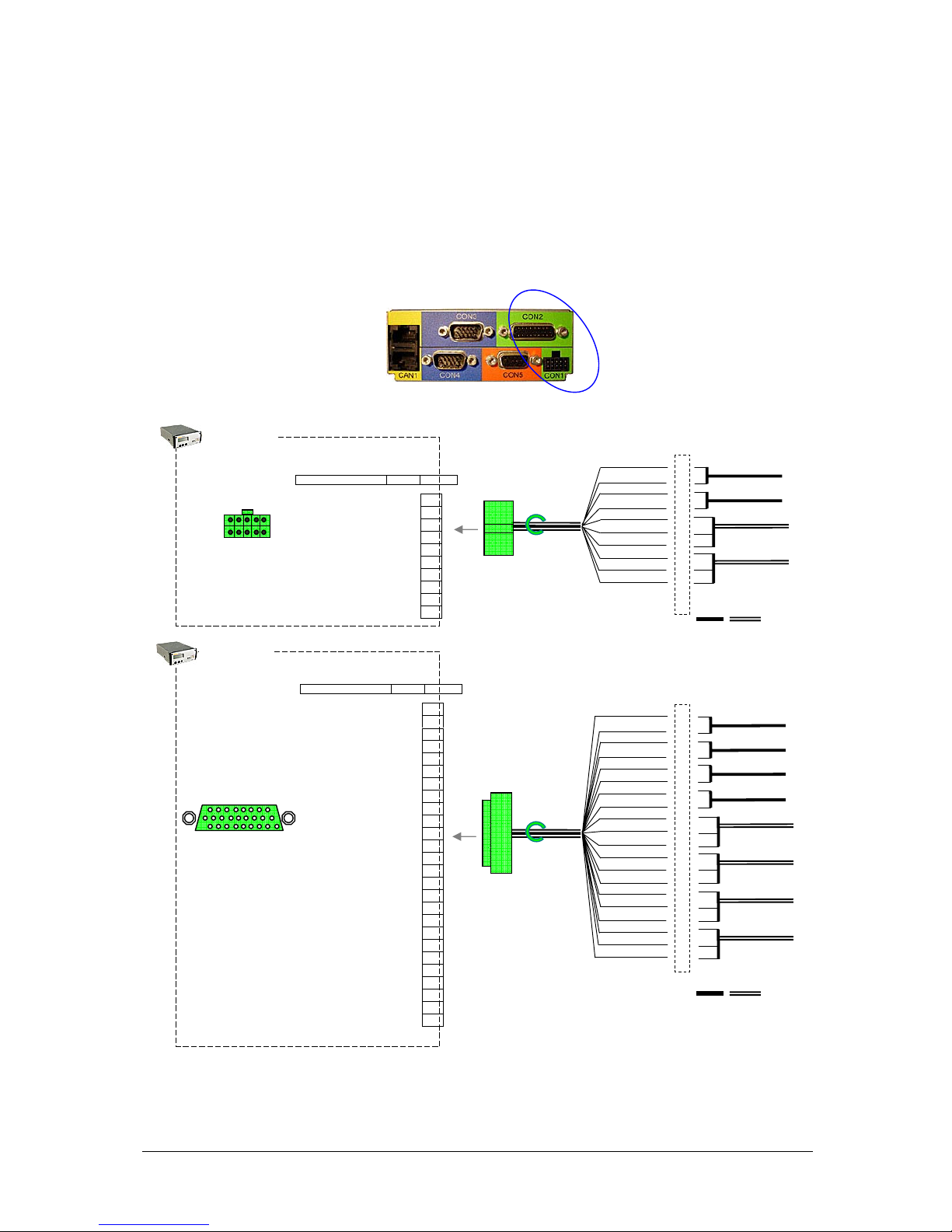
Alarm Relay & Digital Input Signals ⎯ Customer Connections
In standard Smartpack-based DC power systems, the controller’s customer alarm relay
and digital input signals are cabled to dedicated easy accessible terminals, as shown in
Figure 6. See also your system’s specific arrangement drawings.
Figure 6 Overview of customer connections
⎯
alarm relay & digital input signals
A
larm I/O
Connections
CON1
10 pins Connector (male)
Config. Input 1A
−
1
Config. Input 1B + 2
Config. Input 2A − 3
Config. Input 2B + 4
Relay Output 1
COM
5
Relay Output 1 NO 6
Relay Output 1 NC 7
Relay Output 2
COM
8
Relay Output 2 NO 9
Relay Output 2 NC 10
FUNCTION SIGNALPIN-OUT
Smartpack
controller
CON1
(male; green)
1 9
2 10
Interface
Cable 1
+
−
+
−
NO
2
1
4
3
6
5
7
9
8
10
COM
NC
NO
COM
NC
10-pins
plug
female
(Customer
Connections)
Input Circuit 1
Input Circuit 2
A
larm Circuit 1
A
larm Circuit 2
Out In
System Specific Interface
Til
System Specific Interface Terminals
Input Circuit 3
A
larm Circuit 3
Input Circuit 4
Input Circuit 5
Input Circuit 6
A
larm Circuit 4
Alar
m Circuit 5
A
larm Circuit 6
(Customer
Connections)
Out
In
26-pins
D-Sub
male
Interface
Cable 2
+
−
+
−
+
−
+
−
21
20
19
10
1
2
3
4
15
23
6
16
24
7
NO
COM
NC
NO
COM
NC
17
25
8
NO
COM
NC
18
26
9
NO
COM
NC
Ext. Alarm I/O
Connections
CON2
26 pins D-Sub (female)
Config. Input 5B + 1
Config. Input 5A − 2
Config. Input 6B + 3
Config. Input 6A − 4
NC 5
Relay Output 3 NC 6
Relay Output 4 NC 7
Relay Output 5 NC 8
Relay Output 6 NC 9
Config. Input 4A − 10
NC 11
NC 12
NC 13
NC 14
Relay Output 3 NO 15
Relay Output 4 NO 16
Relay Output 5 NO 17
Relay Output 6 NO 18
Config. Input 4B + 19
Config. Input 3A − 20
Config. Input 3B + 21
NC 22
Relay Output 3
COM
23
Relay Output 4
COM
24
Relay Output 5
COM
25
Relay Output 6
COM
26
FUNCTION SIGNALPIN-OUT
19 26
1 9
CON2
(female; green)
Smartpack
controller

2 The Smartpack Controller
10
User’s Guide Smartpack Monitoring & Ctrl Unit,
350003.013, v5-2006-11
CAN Port Signals ⎯ Internal Connections
CAN port 1 and 2 are electrically identical, and
are used to enable connection of the CAN bus
incoming and outgoing CAT5 cables.
A special RJ45 plug with built-in 120Ω end-ofline resistor can be connected to one of the
CAN ports; refer to Figure 8, page 11.
CAN ports’ pin 1&2 may supply the slave
controller with 12VDC, 16W via the CAN bus.
Figur 7 CAN port signals
CAN bus
The Smartpack-based DC power systems utilize the CAN1 bus ⎯ a digital interface
architecture that supports a dedicated communication channel between the controllers
and each of the rectifiers.
CAN bus Addressing
Eltek’s CAN bus may address a maximum of 60 nodes. Among them, you may connect a
maximum of 8 Smartpack controllers and or 50 rectifiers.
Hardware Assignment ⎯ Controllers
The Smartpack controller is factory configured with a
unique CAN bus ID number, using DIP switches on the
side of controller (hardware-assignment). See Figure
3, page 7.
In a distributed DC power system with several
Smartpack controllers, the master is configured with
ID # <1>, the slave with ID # <2> and so on. Refer
to the table in this chapter and Figure 9, page 11.
When a new Smartpack controller is inserted in an existing system, the controller will
recalculate the number of connected rectifiers, reassigning them with the same ID
numbers as they already have in memory. Read “Software Assignment”, page 11.
1
Control Area Network. Serial protocol utilised for communication between Eltek’s
rectifiers and controllers
CAN Bus Connections
Smartpack
controller
CAN port 2
RJ45, 8 pins
CAN port 1
RJ45, 8 pins
CAN1 & 2
2x8 pins RJ45 Connectors
+12V
CS
1
−12VCS 2
+5V
CAN1
3
CANH 4
CANL 5
GND
CAN1
6
+12VCS 7
GND
8
SIGNAL PIN-OUT
Controller ID # DIP Switch Position
1 ⎯ 2 ⎯ 3 ⎯ 4
Master 1 OFF⎯OFF⎯OFF⎯OFF
Slave 1 2 ON⎯OFF⎯OFF⎯OFF
Slave 2 3 OFF⎯ ON⎯OFF⎯OFF
Slave 3 4 ON⎯ ON⎯OFF⎯OFF
Note that the controller’s ID # corresponds to
the DIP switch’s binary value plus one.

2 The Smartpack Controller
User’s Guide Smartpack Monitoring & Ctrl Unit,
350003.013, v5-2006-11
11
Software Assignment ⎯ Rectifiers
Each rectifier in the Smartpack-based DC power system is automatically configured by
the Smartpack controller with a unique CAN bus ID number (software-assignment).
When the rectifiers are hot-plugged in the power shelves the first time, the Smartpack
controller dynamically assigns the rectifiers wit h the next availab le ID number (softwareassignment), and automatically increases the number of communicating rectifiers on the
CAN bus. Also, the controller registers the rectifiers’ ID numbers, or CAN bus address
(01, 02…), together with their serial numbers.
When a previously installed rectifier is hot-plugged in the power shelf again, it retain s its
previous ID and serial number, unless reassigned during a Reset Rectifier command.
CAN bus Termination
To ensure a correct bus communication and avoid data reflection, you must always
terminate the CAN bus with two 120Ω resistors at both ends of the line (60
Ω
bus
impedance), see Figure 8. The CAN bus is connected using CAT5 twisted-pair cables.
Figure 8 CAN bus terminated with a 120Ω resistor on both line ends (60Ω bus impedance)
The example in Figure 9 shows a Flatpack2 DC power system expanded with a slave
controller to implement additional digital inputs, relay outputs or similar functionality.
Figure 9 A Flatpack2 DC power system expanded with two controllers
120Ω
Flatpack2
DC Power System
End-of-Line
Resistor
End-of-Line
Resisto
r
120
Ω
CAN bus
(twisted-pair internal CAT5 cable)
USB A-B cable
(standard)
01 02 n
1
Smartpack assigns ID numbers to the rectifiers (software-assigned). The Smartpack’s
ID numbers are assigned by DIP switches
on the controller’s side.
120Ω
Flatpack2
DC Power System
End-of-Line
Resistor
01 02 3
1
Smartpack controlle
r
Master
120Ω
End-of-Line
Resisto
r
n+1
n+2 m
2
Smartpack controlle
r
Slave 1
Slave controlle
r
DIP switch
configuration
ID <2>
(Switch #1 ON, the
rest OFF)
Master controller
DIP switch configuration
ID <1>
(All switches OFF)
Alarm Outputs
NC-C-NO
Digital Inputs
Alarm Outputs
NC-C-NO
Digital Inputs
4 n

2 The Smartpack Controller
12
User’s Guide Smartpack Monitoring & Ctrl Unit,
350003.013, v5-2006-11
Firmware Upgrade of the Smartpack controller
You can use the FWLoader program2 running on a PC to upgrade the Smartpack
controller’s firmware. To find your controller’s firmware version, refer to page 23. The
PowerSuite program has to be installed previously on the PC. Do following:
1. Connect a PC to the Smartpack
using a standard USB cable
2. Start the FWLoader program on the PC;
On the FWLoader dialog box:
3. Select “Smartpack”, in Target Selection
4. Select “1”, in Target Address
5. Select “COMx”
in Communication Type. Refer to the
PowerSuite program to find the
communication port the PC uses to
communicate with the controller.
6. Click on the “Open Source F ile” button and,
Select the file “*.mhx”
that contains the firmware to upgrade the
controller with
7. Click on the “Write to Target” button,
to load the firmware to the Smartpack
controller
Figure 10
FWLoader dialog box
While the firmware is loaded to the Smartpack controller, the FWLoader program displays
a progress bar, and the controller’s display shows the currently programmed segment.
Once the firmware has loaded, the Smartpack controller will automatically restart.
2
You can get a copy of the FWLoader progam by contacting Eltek’s Service Dep.
3
4
5
6
7

2 The Smartpack Controller
User’s Guide Smartpack Monitoring & Ctrl Unit,
350003.013, v5-2006-11
13
Module Options
The Smartpack is a scalable controller with modular design. It can be optimized for
different requirements by means of plug-in-kits. Various Smartpack controller options are
available offering remote control management via modem, Web, e-mail and SNMP.
Smartpack Controller ⎯ Standard
Figure 11 The standard Smartpack controller. Front and rear connections
The Smartpack controller – in standard option, Art 242100.110 – allows local monitoring
and control via the module’s front keys, LED lamps, LCD display and via a PC connected
to the USB port.
The controller’s functionality can be expanded by connecting several Smartpack
controllers to the CAN bus (distributed DC power system). See Figure 9, page 11.
For more detailed description of connectors, see Figure 4, page 7.
Smartpack Controller ⎯ Ethernet
Figure 12 The Smartpack controller, Ethernet option. Front and rear connections
The Smartpack controller – in Ethernet option, Art 242100.113 – allows remote system
monitoring and control via the Ethernet port, using TCP/IP network protocol. Connect a
10/100 Base T screened Ethernet cable to the Ethernet port.
The Ethernet plug-in-kit incorporates an embedded Web adapter, supporting Web/HTML
interface, remote logon by PowerSuite, SNMP protocol (Get, Set, Traps) and e-mail alert
via your network e-mail server. For description of the functionality provided by the
embedded the Web adapter, read the WebPower Adapter manual, Art. 356943.013.
The Smartpack’s standard and Ethernet options offer otherwise the same functionality,
except for the Alarm I/O Connections on CON2, which are replaced by the Ethernet plugin-kit.
Thus the Ethernet module option supports fewer I/O connections -- four input circuits
and four relay output circuits less. See Figure 6, page 9.
Smartpack controller
Standard
Front View
A
larm I/0 Connections
CAN port (2)
Battery Connections
Battery Connections
System Connections
A
larm I/0 Connections
Rear View
USB port
Ethernet port
RJ45 connector
Smartpack controller
Ethernet
Front View
Rear View
Other connectors are
compatible with the
Smartpack standard
option

2 The Smartpack Controller
14
User’s Guide Smartpack Monitoring & Ctrl Unit,
350003.013, v5-2006-11
Smartpack Controller ⎯ RS232
The Smartpack controllers – in RS232 option, Art 242100.111 (front access) and Art
242100.112 (rear access) – allow remote system monitoring and control by connecting
to the RS232 port either a modem or Eltek’s stand-alone WebPower unit (Ethernet
support).
RS232 option Front Access
Figure 13 The Smartpack controller, RS232 option, front. Front and rear connections
The Smartpack’s standard and front-access RS232 options offer otherwise the same
functionality.
RS232 option Rear Access
Figure 14 The Smartpack controller, RS232 option, rear. Front and rear connections
The Smartpack’s standard and rear-access RS232 options offer otherwise the same
functionality, except for the Battery Connections on CON3, which are replaced by the
RS232 plug-in-kit.
Thus the rear-access RS232 module option supports fewer battery connections – seven
battery monitoring input circuits less. See Figure 5, page 8.
RS232 Port Signals
The RS232 ports on the front-access and the
rear-access module options are electrically
identical.
Connect an end of the RS232 cable to the
Smartpack’s RS232 port, and the other end to
the modem’s or WebPower’s RS232 port.
Verify that both units have the same
communication parameters (Baud rate, parity,
etc.)
Figure 15 RS232 port signals
Smartpack controller
RS232, front
Front View Rear View
Other connectors are
compatible with the
Smartpack standard
option
RS232C port
RJ45 connector
Smartpack controller
RS232, rear
Front View
Rear View
Other connectors are
compatible with the
Smartpack standard
option
RS232C port
RJ45 connector
Communication Cable
9 pins D-Sub (male)
CON3
9 pins D-Sub (female
)
1
2
3
4
5
6
7
RS232C, TxD
RS232C, RxD
(
Not Used)
GND
(
Not Used)
RS232C, CTS
8
RS232C, RTS
9
(
Not Used)
(On the controller’s front)

2 The Smartpack Controller
User’s Guide Smartpack Monitoring & Ctrl Unit,
350003.013, v5-2006-11
15
Smartnode Module
Figure 16 The Smartnode module. Front and rear connections
The Smartnode module is a software protocol translator. It can be customized to enable
the Smartpack controller to communicate with third-party equipment using specific
RS232 and RS485 serial protocols.
Figure 17 The Smartpack controller communicating with the Smartnode module
The example in Figure 17 shows schematics of how the Smartpack controller can
communicate with external equipment with specific protocols, using the Smartnode as a
protocol translator.
Smartnode
module
Front View
Rear View
RS232C port
RJ45 connector
CAN port (2)
RS485 port
RJ45 connector
Smartpack
controller
CAN bus
(twisted-pair CAT5 cable)
RS232 cable
(to external equipment)
RS485 cable
(to external equipment)
Smartnode
module
3 Installation of Smartpack Controller
16
User’s Guide Smartpack Monitoring & Ctrl Unit,
350003.013, v5-2006-11
3. Installation of Smartpack Controller
Safety precautions
Get acquantied with the satety precautions on page 2, before installing or handling
the equipment.
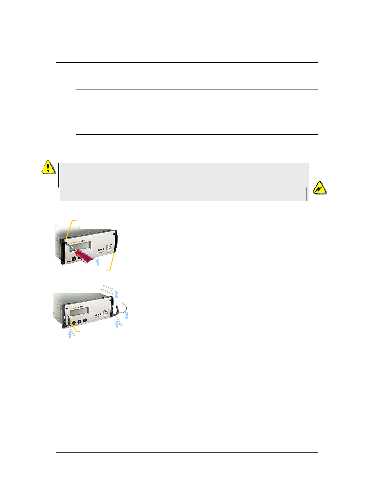
Mounting and Removing the Controller
The Smartpack controller incorporates handles that serve both to lock the module
into position and to pull it out of its housing.
Mounting the Smartpack controller
1. Open the handles by
inserting a screwdriver into the holes to release the
spring mechanism
2. Insert the module fully into the power shelf, after
plugging the cables to the rear panel
3. Lock the handles by
pushing the handles up into their housings (locked
position), so that the module is securely locked
Removing the Smartpack controller
1. Open the handles by
inserting a screwdriver into the holes to release the
spring mechanism
2. Remove the module by
using both handles to pull the module loose gently;
support from underneath; unplug the cables connected
to the rear panel
Figure 18 Smartpack controller’s locking mechanism
Removing Blind Panels
Release the panel’s upper left and right corners by inserting a small screwdriver
into the panel’s upper left gap, and carefully press down and out to release the
locking tabs. Repeat on the upper right gap. Refer to the Flatpack2 system’s quick
start guide for more information.
Smartpack
controller
Handle in locked position
Hole to release the
handle’s spring
mechanism
Handle in
unlocked
p
osition
Device
hazard
CAUTION: Do not hand-carry the controller by its handles. Cables are
plugged to the controller’s rear panel. Open the handles before inserting the
controller into the power shelf.
Mount blind panels in unused module locations.
Electric
shock

4 Front Panel Operation
User’s Guide Smartpack Monitoring & Ctrl Unit,
350003.013, v5-2006-11
17
4. Front Panel Operation
This chapter describes the Smartpack controller’s keys and indicators, and how to
operate the Smartpack-based DC power system from the controller’s front panel.
Description of Keys, Display and Indicators
The Smartpack controller’s front panel consists of two functional areas: the presentation
area (LCD display and LED lamps) and the control area (keys). For information about the
handles and the USB port, read pages 7 and 16.
Figure 19 Smartpack controller’s front keys and indicators
LED indicators
The Smartpack controller has the following LED indications:
•
“Power” (green) indicates that the power supply is ON or OFF
•
Alarm (red) indicates an alarm situation (major alarm)
•
Warning (yellow) indicates an abnormal situation (minor alarm)
LCD Display
The graphic display is an important part of the power supply system’s user interface. The
display is in Status Mode (displays the system’s status) or in Menu Mode (displays the
menu structure).
Depending on the display’s mode, the upper line shows the output voltage or menu
options, while the lower line displays battery and load current, alarms, or information
about which key to press. See also chapter “Modes of Operation”, on page 18.
Front Keys
You can control the whole Smartpack-based DC power system via a network of software
menus accessed with the controller’s front keys.
o Press on the
key to change from Status Mode to Menu Mode .
o Press the
or keys to scroll up or down and navigate to find menu options
(function or parameter).
o Press then the
key to select the function.
Power
LED Lam
p (g
reen
)
Warning
LED Lam
p (y
ellow
)
Alarm
LED Lamp (red
)
Graphical Displa
y
16 character x 2 lines LCD displa
y
”Up” arrow key
”Down” arrow key
”Enter” key
Upper line
Output voltage o
r
menu options
Lower line
Battery or load current,
alarms, or keys to press

4 Front Panel Operation
18
User’s Guide Smartpack Monitoring & Ctrl Unit,
350003.013, v5-2006-11
Modes of Operation
The controller’s display is either in Status Mode or in Menu Mode.
Status Mode
When the front keys are not in operation, the display is in Status Mode. The following
information is then scrolled through the display:
• The upper line continuously displays the battery voltage.
• The lower line continuously scrolls the following information:
o Battery Current
o Load Current
o Active alarms
o Other messages
Menu Mode
When the front keys are in operation, the controller’s display switches to Menu Mode and
the following information is scrolled throug h the display:
• The upper line shows the name of the active menu or sub-menu
• The lower line indicates which key to press
Notice that if no keys are pressed within 30 seconds, the display will automatically switch
from Menu Mode and to back to Status Mode.
Operating Menus, Overview
The Smartpack-based DC power system’s functionality is accessed via a network of
software menus and submenus, enabling you to configure and control the whole power
system.
The functionality is divided in two different hierarchical
menu structures: the User Options menus and the
Service Options menus (password protected, only
authorised personnel have access to them).
Special, not so frequently used options — such as
calibration and adjustments — are accessible in the
Service Options sub-menus.
Display in Status Mode
UserOption
ServiceOption
Level 1

4 Front Panel Operation
User’s Guide Smartpack Monitoring & Ctrl Unit,
350003.013, v5-2006-11
19
User Options
UO
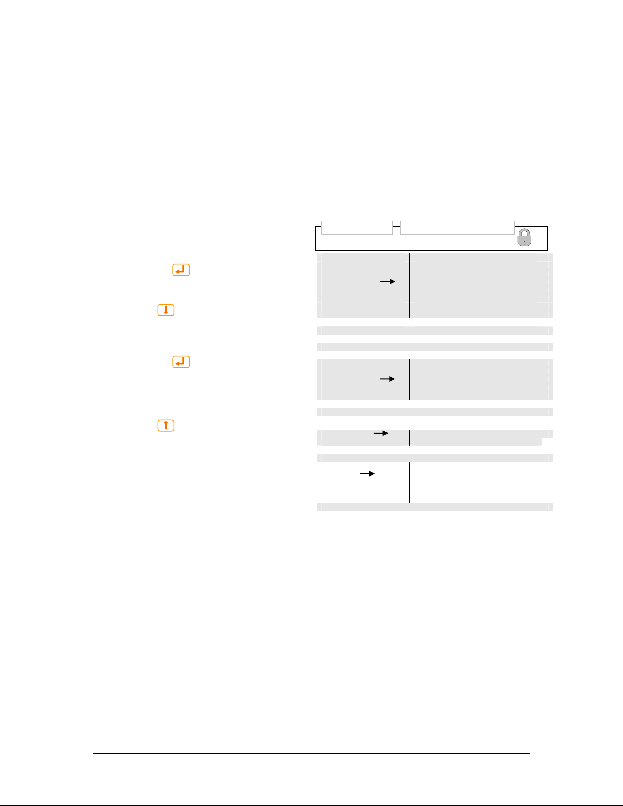
When you “enter” Menu Mode, you access the User Options.
For description of the User menu options, read chapter “Functionality Description” page
22. Also, refer to the PowerSuite online Help system.
How to browse the display menus
o Entering Menu Mode
Press on the
key to change from
Status Mode to Menu Mode
o Browsing “down” to a menu option
Press the
key, to scroll down within
the same menu level, and find menu
options (functions or parameters)
o Selecting a menu option
Press on the
key to select the
displayed menu option or parameter
o Browsing “up” to a menu option
or level
Press the
key to scroll up to the
previous menu option, and out to the
previous menu level.
User menu <UserOption>
AlarmReset
NomVolt
BoostVolt
LoBattMaj
VoltageInfo LoBattMin
HiBattMaj
HiBattMin
LVBD
LVLD 1.1
DisplayMessages
Message ↓↑
SoftwareInfo
SerialNumber
NoOfRects. nn
RectCurrent
Rectifier Info RectSerialNumber
Rect.PrimaryVolt
Rectifier Status
Rectifier Temp
Rect. OutputVolt
Rectifier SW Ver
NoOfPhases nn
Mains Info Mains Status
Mains Voltage
Temp Level Info
Level ↓↑
NoOfString Nn
BattStringCurr ↓↑
Battery Info
BattStringTemp ↓↑
BattBlockVolt ↓↑
Level 2 Level 3
…
Firmware 402073.003 1v00
4 Front Panel Operation
20
User’s Guide Smartpack Monitoring & Ctrl Unit,
350003.013, v5-2006-11
Service Options
SO
When you enter Menu Mode, you access the User Options. You may then scroll down to
the password protected Service Options.
The Service Option’s password is factory-programmed to <0003>. We strongly
recommend that this password is changed as soon as the system is installed
For description of the Service menu options, refer to the PowerSuite online Help system.
How to browse the display menus
o Entering Menu Mode
Press on the
key to change from
Status Mode to Menu Mode
o Browsing “down” to a menu option
Press the
key, to scroll down within
the same menu level, and find menu
options (functions or parameters)
o Selecting a menu option
Press on the
key to select the
displayed menu option or parameter
o Browsing “up” to a menu option
or level
Press the
key to scroll up to the
previous menu option, and out to the
previous menu level.
Service menu <ServiceOption>
NomVolt ↓↑
BoostVolt ↓↑
LoBattMaj ↓↑
V
oltAdjustment
LoBattMin ↓↑
HiBattMaj ↓↑
HiBattMin ↓↑
LVBD ↓↑
LVLD 1.1 ↓↑
V
oltCalibration
VoltCal ↓↑
ChangePassword
Password ↓↑
SetManBoostTime
↓↑
Start/StopBoost
A
uto Boost Conf.
Enable/Disable ↓↑ & Th
r
eshold
Nxt Test DateTime Date ↓↑Time
End Volt ↓↑
Batt Test Setup
MaxTestDur ↓↑
Test Int ↓↑
Guard Time ↓↑
Start/Stop Test
NoOfRects. ; nn Reset
Charge Curr Lim.
Enable/Disable ↓↑ & Max
Battery Setup
NumOfString ↓↑
CellCap Ah nn ↓↑
Output Control
Volta
g
eCtrl / TempComp↓
Change Date/Time
Date ↓↑ Time ↓↑
Alarm Output 1 ↑
RelayTest
Alarm Output 2 ↑
Batt Contactor ↑
Load Contactor ↑
Alarm Output nn ↑
BattLifeTime Rst
Level 2 Level 3
…
Firmware 402073.003 1v00

5 Technical Specifications
User’s Guide Smartpack Monitoring & Ctrl Unit,
350003.013, v5-2006-11
21
5. Technical Specifications
Remote Monitoring / Control
From a PC running Windows-based
communication software (PowerSuite)
With the Windows-based communication program
installed on a remote computer, the system can be
monitored and controlled via modem or Ethernet
network.
From an NMS via Ethernet (SNMP)
With an SNMP agent connected to the Smartpack, th e
system can be monitored and controlled from a
Network Management System (NMS) through
Ethernet on Simple Network Management Protocol
(SNMP).
Using alarm relays (voltage free contacts)
6 internal failsafe alarm relays provide voltage free
contacts that can be connected to equipment used
for traditional alarm monitoring.
Features
System
Output Voltage Measurement
Total Load Current Measurement
Load/Battery Disconnect
Alarm Level Settings (major / minor)
Alarm Log (up to 1000 events)
Real Time Clock with Battery Backup
Site Text/ID
Test of Relay Outputs
Voltage Level setup
Battery
Battery Current Measurement
Battery Temperature Measurement (optional)
Battery Testing (acc. to discharge table or set ti me
limit)
Battery Test Information (10 latest tests)
Setup of Battery Data
Battery shunt setup
Battery quality indication
Battery Boost Charging
Battery Cable Voltage Drop Compensation
Temperature Compensated Charging
Protection against Temperature Probe Failure
Rectifier
Available information about each rectifier, e.g. serial
number, version, internal temperature
Individual Rectifier Current Measurement
Individual Rectifier Input Voltage
Local Monitoring / Control
From a PC running Windows-based
communication software (PowerSuite)
Windows-based comm. software can also
communicate with the Smartpack through an USB
serial or RS-232 cable.
LCD and three keypads for local operations.
If any alarm (major or minor) is activated, a (red or
yellow) LED is lit in the front panel, the alarm text
appears in the LCD and the corresponding alarm relay
is activated.
In normal operation, the front LCD will display the
output voltage, battery current, load current and
charge mode.
Specifications
Input Voltage 24/48/60 VDC
(Nominal system voltages)
Firmware The Smartpack main program can
be upgraded via the USB port,
using a PC running the FWLoader
application
Dimensions 109 x 44 (1U) x 140mm (wxhxd)
(4.3 x 1.7 x 5.5”)
Available Alarms
All alarms can be set up with monitoring of
minor, major, average and peak levels.
System
Mains Failure (individual phases)
Digital Inputs (programmable names)
Load Disconnect (voltage or timer)
Load Fuse
Load Current
Battery
High Battery voltage
Low Battery voltage
High Battery temperature
Low Battery temperature
Battery Capacity
Battery Disconnect
Battery Fuse
Symmetry Failure
Battery quality indication
Battery discharge current
Rectifier
Rectifier Failure
Critical Rectifier Failure (> 1, pro g rammable)
Rectifier Capacity w. programmable level
Rectifier Current Limit
Rectifier Over voltage Protection
Rectifier Current

6 Functionality Description
22
User’s Guide Smartpack Monitoring & Ctrl Unit,
350003.013, v5-2006-11
6. Functionality Description
In this chapter you can find helpful and more detailed descriptions of expressions,
technical terms, functions, etc. used in Smartpack-based DC power systems.
Alarm Reset
UO (AlarmReset)
You can reset all active alarms by selecting “UserOption>AlarmReset”, via the
Smartpack controller’s front keys. The controller will imm ediately report alarm conditions
that are still active.
The Smartpack-based DC power system can be configured with automatic or manual
alarm reset.
When Automatic Alarm Reset is enabled (default) ⎯ and the alarm condition no longer
exists ⎯ the Smartpack controller will deactivate the alarm lamps and relays to indicate
that normal operation is established.
When Manual Alarm Reset is enabled ⎯ and the alarm condition no longer exists ⎯ the
operator must reset the alarm manually.
Display System Voltages
UO (VoltageInfo)
You can display important system voltages by selecting “UserOption>VoltageInfo”,
via the Smartpack controller’s front keys.
Following voltages may be displayed selecting the VoltageInfo sub options (level 3):
Option Description
NomVolt Nominal output voltage
BoostVolt Battery boost-charging voltage
LoBattMaj Voltage limit for Low Battery Major Alarm
LoBattMin Voltage limit for Low Battery Minor Alarm
HiBattMaj Voltage limit for High Battery Major Alarm
HiBattMin Voltage limit for High Battery Minor Alarm
LVBD Voltage limit for Low Voltage Battery Disconnect
LVLD 1.1 Voltage limit for Low Voltage Load Disconnect
Display Alarm Messages, (Log)
UO (DisplayMessages)
You can browse through the stored system alarm messages (alarm log) by selecting
“UserOption>DisplayMessages”, via the Smartpack controller’s front keys.
The Smartpack controller’s alarm log may store up to 1000 chronological events. Each
log entry contains event text, event action, time and date. When the log is full, the oldest
value is overwritten. The log is stored in EEPROM.

6 Functionality Description
User’s Guide Smartpack Monitoring & Ctrl Unit,
350003.013, v5-2006-11
23
Display Controller’s Firmware Version
UO (SoftwareInfo)
You can display the Smartpack controller’s firmware3 and version numbers by selecting
“UserOption>SoftwareInfo”, via the Smartpack controller’s front keys.
The firmware and version numbers are displayed in the format <nnnnnn.yys vv.vv>.
The “nnnnnn.yys” represents the firmware number. The “s” is a code for the firmware
language: 1= Norwegian, 2= Swedish, 3= English, 4= German, 5= French, 6= Spanish,
etc.
The “vv.vv” represents the firmware’s version number.
Display Controllers’ Serial Numbers
UO (SerialNumber)
You can display the Smartpack controllers’ serial numbers by selecting
“UserOption>SerialNumber”, via the Smartpack controller’s front keys.
The serial numbers are displayed in the format <cc: nnnnnnnnnnnn>.
The “cc:” represents the ID or CAN bus address of the Smartpack controller with serial
number “nnnnnnnnnnnn”. Press the
or keys to display the serial numbers of
other controllers in the CAN network.
Display Rectifier Information
UO (Rectifier Info)
You can display information about the rectifiers commu nicating in the Smartpack-based
DC power system, by selecting “UserOption>Rectifier Info”, via the Smartpack
controller’s front keys.
Following information may be displayed selecting the Rectifier Info sub options (level 3):
Option Description
NoOfRects. Nn Number of rectifiers installed in the system.
RectCurrent Rectifier’s current
RectSerialNumber Rectifier’s ID and serial number
Rect.PrimaryVolt Rectifier’s input v oltage
Rectifier Status Rectifier’s status
Rectifier Temp Rectifier’s temperature
Rect. OutputVolt Rectifier’s output voltage
Rectifier SW Ver Rectifier’s firmware version
While the controller is accessing inf ormation from a specific rectifier, the green LED on
the rectifier’s front panel flashes.
The Smartpack controller sends out status messages every 200ms to all the rectifiers
connected to the CAN bus, such as:
o The Smartpack controller’s status
o Current Limit Reference
o Measured Output Voltage
o Reference Output Voltage
o Over-voltage Protection Reference
o Etc.
3
The main program (firmware) is stored in flash memory chips.

6 Functionality Description
24
User’s Guide Smartpack Monitoring & Ctrl Unit,
350003.013, v5-2006-11
Plug-and-Play Rectifier
When a rectifier is hot plugged in a power shelf for the first time, the Smartpack
controller assigns the next available ID number to the rectifier, starting with “01”. This ID
number (or CAN bus address) and the rectifier’s serial number are stored in both
modules.
When a previously insta lled (hot plugged) rectifier is inserted in a power shelf, the
Smartpack controller “recognises” the module, and assigns the same ID to rectifier.
In other words, the controller and the rectifier “remember” the assigned ID and serial
numbers, even after removing and reinserting the rectifier in the shelf.
To achieve a more controlled ID assignment, you should always insert & hot-plug new
rectifiers in the indicated power shelf position, one module at a time, starting
with ID number 1, 2, 3 and so on. The sequence is indifferent after ID# 6. Read
chapter “Mains Phase Assignment versus Rectifier ID”, page 24.
The rectifiers’ power shelf positions vary with the type of AC mains and the type of power
shelves installed in your system. Refer to your system’s quick start guide and specific
documentation for more information.
Do not relocate already pre- installed rectifiers.
Mains Phase Assignment versus Rectifier ID
In systems with 3 phase AC feed, the Smartpack controller can be configured to report a
warning if one phase fails, and to report an alarm if two phases fail, for example.
The 230V phases of Flatpack2 systems’ mains AC feed are routed to the rectifiers’ inputs
in a special pattern that loads the 3 phases evenly. The routing of the phases is
implemented via internal wiring and the use of either 4AC Power Shelves
4
or 2AC
Power Shelves5. Refer to your system’s quick start guide and specific documentation
for more information.
To be able to display correct information about the phases, the Smartpack controller
must “know” which phase is connected to which rectifier ID number.
Flatpack2 DC power systems are shipped from factory with empty power shelves. The
rectifier modules are shipped in separate packaging, and y ou have to install the modu les
in the correct position in the power shelves, with respect to their ID number (or CAN
bus address).
This relationship is very important, as the Smartpack controller always uses rectifier ID
01, 02 and 03 to monitor mains phase L1, L2 and L3 respectively. If these rectifiers
malfunction, rectifier ID 04, 05 and 06 will automatically take over.
For example: accidentally inserting a rectifier with ID 02 in a power shelf position
internally connected to mains phase L1, will cau se the controller to monitor L1 “th inking“
it monitors L2. Then a phase 1 fault will be alarmed as a phase 2 fault.
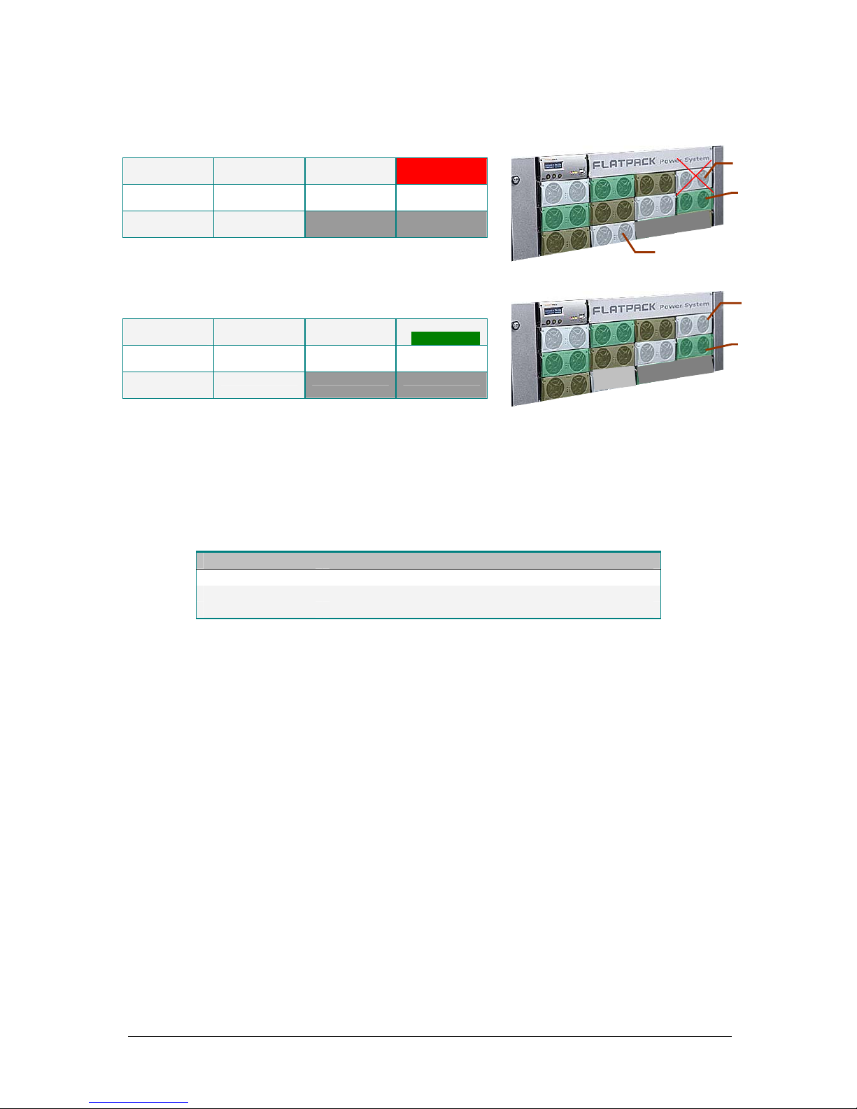
Resetting the Number of Rectifiers
When a rectifier reset is activated, the number of rectifiers is recalculated, and only the
number of communicating modules at the moment will be counted.
For instance: in a Flatpack2 DC power system equipped with 10 rectifiers, rectifier with
ID number “04” malfunctions. If you insert rectifier ID#10 in th e position of the failing
ID#04, and then activate a rectifier reset, the Smartpack controller recalculates the
number of communicating rectifiers to only 9. At the same time the controller reassigns
rectifier with ID#10 to ID#04, thus filling the gap.
4
4AC Power Shelves (Single AC feed: 4 AC inputs per shelf, each feeding 1 rectifier).
5
2AC Power Shelves (Dual AC feed: 2 AC inputs per shelf, each feeding 2 rectifiers).
6 Functionality Description
User’s Guide Smartpack Monitoring & Ctrl Unit,
350003.013, v5-2006-11
25
Example: Flatpack2 DC power system with malfunctioning rectifier;
3 power shelves with 10 rectifiers (rectifier ID #04 malfunctions)
Rectifier ID 01
Serial No. 01
Rectifier ID 02
Serial No. 02
Rectifier ID 03
Serial No. 03
Rectifier ID 04
Serial No. 04
Rectifier ID 05
Serial No. 05
Rectifier ID 06
Serial No. 06
Rectifier ID 07
Serial No. 07
Rectifier ID 08
Serial No. 08
Rectifier ID 09
Serial No. 09
Rectifier ID 10
Serial No. 10
After rectifier reset:
3 power shelves with 9 rectifiers
(rectifier ID #10 reassigned to #04)
Rectifier ID 01
Serial No. 01
Rectifier ID 02
Serial No. 02
Rectifier ID 03
Serial No. 03
Rectifier ID 04
Serial No. 10
Rectifier ID 05
Serial No. 05
Rectifier ID 06
Serial No. 06
Rectifier ID 07
Serial No. 07
Rectifier ID 08
Serial No. 08
Rectifier ID 09
Serial No. 09
Display System Mains Data
UO (Mains Info)
You can display information about the power system’s AC feed by selecting
“UserOption>Mains Info”, via the Smartpack controller’s front keys.
Following data may be displayed selecting the Mains Info sub options (level 3):
Option Description
NoOfPhases nn Number of Mains phases in the system’s AC feed
Mains Status The status of each of the phases
Mains Voltage The AC voltage of each of the phases
Display Battery Temperature Levels
UO (TempLevel Info)
You can display how many hours the system’s battery bank has been within a certain
temperature range (level) by selecting “UserOption>TempLevel Info”, via the
Smartpack controller’s front keys.
The information is displayed in the format [nn: <ddC hhhhhH], which means:
• nn: The number of the temperature range or level (01 through 10)
• <ddC The range’s upper temperature value, in degrees Celsius
• hhhhhH The number of hours the battery bank has been within the
temperature range
Using the PowerSuite program, you configure the Battery Lifetime Temperature monitor
to automatically activate an alarm when the system’s battery bank has been within a
temperature range (or level) longer that a certain period of time. For each of the 10
temperature ranges, you can configure the upper and lower temperature values, and the
time limit.
01 02
05
06
09
10
03
04
07
08
---
---
---
---
ID “04”
SNo.: 04
ID “10”
SNo.: 10
Flatpack
2
rectifie
r
01 02
05
06
09
04
03
07
08
---
---
---
---
ID “04”
SNo.: 10
Flatpack
2
rectifie
r

6 Functionality Description
26
User’s Guide Smartpack Monitoring & Ctrl Unit,
350003.013, v5-2006-11
The table shows an example of values entered in the Battery Lifetime Temperature
monitor.
Temperature Range Time within Range
Range # Low Limit, °C High Limit, °C Hours
01 00 10 10
02 11 20 20
03 21 30 60
04 31 40 40
05 41 50 05
06 51 60 00
07 61 65 00
08 66 70 00
09 71 75 00
10 76 99 00
You can reset the values in the Battery Lifetime Temperature monitor either by selecting
“ServiceOption>BattLifeTime Rst”, via the Smartpack controller’s front keys, or using
PowerSuite.
Display Battery Information
UO (BatteryInfo)
You can display information about the power system’s battery bank by selecting
“UserOption>Battery Info”, via the Smartpack controller’s front keys.
Following data may be displayed selecting the Battery Info sub options (level 3):
Option Description
NoOfString Nn Number of battery strings
BattStringCurr Each battery string’s current
BattStringTemp Temperature of each battery string
BattBlockVolt Voltage of each battery block
For battery terminology, refer to chapter “About Battery Banks, Strings and Blocks”,
page 26 and to the “Quick Start Guide Flatpack2 PS System”, Art. 356804.103.
About Battery Banks, Strings and Blocks
Normally, battery banks are implemented by
connecting in parallel several battery strings; each
string is formed by battery blocks connected in series.
Figure 20 Example of a 48V battery bank
implemented with two 48V battery strings; each
string consists of four 12V battery blocks
48V Battery Bank
Battery
String #1
(48V)
Battery
Block (12V)
Battery
String #2
(48V)

6 Functionality Description
User’s Guide Smartpack Monitoring & Ctrl Unit,
350003.013, v5-2006-11
27
Battery Symmetry Measurements ⎯ 48V Systems
Symmetry measurement is a battery monitoring method for automatically detecting
unbalanced battery blocks.
For information about 24V systems symmetry measurements, read the “Quick Start
Guide Flatpack2 PS System” Art. 356804.103.
Symmetry monitoring of a 48V battery string may be
performed after three different methods:
o Block measurement method
Measuring each battery block
o Mid-point measurement method
Measuring from the mid-point of the battery
string to one end
o Double mid-point measurement method
Measuring from the mid-point of the string to
both ends
The mid-point measurement method requires 2
symmetry wires per battery string; the double mid-
point measurement method requires 3 symmetry wires
per battery string, while the block measurement
method requires 5 symmetry wires per battery string.
Refer to the system’s quick start guide for connections.
Cabinetized DC power systems are normally delivered
with the symmetry measurement method and the
number of measurement points already
preprogrammed in the Smartpack controller. Any
deviation from factory settings requires Symmetry
reconfiguration via the PowerSuite PC program.
Each Smartpack controller is equipped with 8 battery
symmetry inputs (on CON4 and CON3), enabling
symmetry measurement of:
o 2 battery strings (block meas. method)
o 4 battery strings (double mid-point meas. method)
o 8 battery strings (mid-point meas. method)
Figure 21 Example of terminal connection points for Symmetry Block, Mid-point and
Double Mid-point measurement methods in 48V systems
Battery Symmetry
Block Measurement
Four measurement points per string
(Serial measurement)
Card, Art. 200576
Serial Switches
Set all 4 switches
ON (down)
Symmetry
1 2 3 4
+ (0V)
— (-48V)
-
+
+ + +
Battery Symmetry
Mid-point Measurement
One measurement point per string
Symmetry 1
+
+ (0V)
— (-48V)
Card, Art. 200576
Serial Switches
Set all 4 switches
OFF (up)
Battery Symmetry
Double Mid-point Measurement
Symmetry
2
+
+ (0V)
— (-48V)
Symmetry
1
+
-
Card, Art. 200576
Serial Switches
Set all 4 switches
ON (down)
Two measurement points per st
r
ing,
from the middle to the outer terminals

www.eltekenergy.com
ELTEK Energy
P-O- BOX 2340 StØmsØ
N-3003 DRAMMEN
NORWAY
Phone: +47 32203200
Telefax: +47 32203210
Internet: http://www.eltekenergy.com
e-mail:
eltek@eltekenergy.com
Location Company Telephone Fax
Norway Eltek Energy AS +47 32 20 32 00 +47 32 20 32 10
Americas Eltek Energy, LLC +1 815 459 9100 +1 815 459 9118
Asia/Pacific Eltek Energy Pte Ltd. +65 6 7732326 +65 6 7753602
China Eltek Energy Ltd. +769 22651108
Europe Eltek Energy UK Ltd. +44 1442 219355 +44 1442 245894
Middle East Eltek Middle East +971 4 887 1176 +971 4 887 1175
 Loading...