

Eltek PSR312 User Manual
RECTIFIER
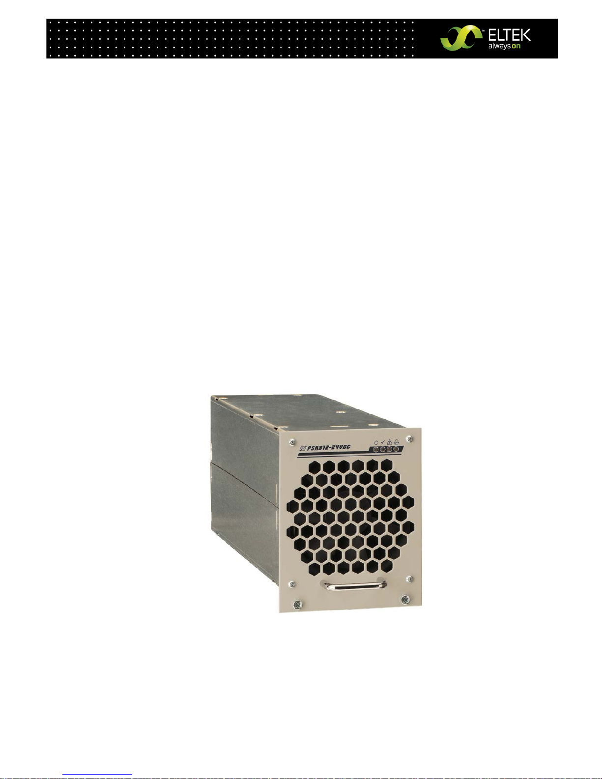
PSR312
USER MANUAL
Eltek_UM_PSR312_21TE_E_R6.0

Rectifier
PSR312
User Manual
Page 2 (20)
©2011. ELTEK DEUTSCHLAND GmbH.
Eltek_UM_PSR312_21TE_ E_R6.0
Notes to this manual
ATTENTION! Read this manual very carefully before installing and commissioning the specified module.
This manual is a part of the delivered module. Familiarity with the contents of this manual is required for
installing and operating the specified module.
The rules for prevention of accidents for the specific country and the general safety rules in accordance
with IEC 364 must be observed.
The function description in this manual corresponds to the date of publishing.
Technical changes and changes in form and content can be made at any time by the manufacturer
without notice. There are no obligations to update the manual continually.
The module is manufactured in accordance with applicable DIN and VDE standards such as VDE 0106
(part 100) and VDE 0100 (part 410). The CE marking on the module confirms compliance with EU
standards 2006-95-EG (low voltage) and 2004-108-EG (electromagnetic compatibility) if the installation
and operation instructions are followed.
Supplier:
ELTEK DEUTSCHLAND GmbH
BU Industrial
Schillerstraße 16
D-32052 Herford
+ 49 (0) 5221 1708-210
FAX
+ 49 (0) 5221 1708-222
Email
Info.industrial@eltek.com
Internet
http://www.eltek.com
Please note: No part of this document may be reproduced or transmitted in any form or by any means electronic or mechanical, including photocopying and recording- for whatever reason without the explicit
written permission of Eltek Deutschland GmbH.
Changes and errors excepted.
2011. ELTEK DEUTSCHLAND GmbH. All rights reserved.

Rectifier
PSR312
User Manual
Page 3 (20)
©2011. ELTEK DEUTSCHLAND GmbH.
Eltek_UM_PSR312_21TE_ E_R6.0
The current revision status of this user manual is the following:
Revision: 6.0
Date: 2010-11-23
Revision
Description of change
Writer
Date
00 First edition RTH 2008-01-03
01
Minor text modifications, sections “Commissioning”, “Output
power diagram” and “Monitoring” reworked, index of figures
inserted.
RTH 2008-05-15
1.2
Minor text modifications, new revision status numbering
introduced.
RTH 2008-11-04
2.0
Section 4.2.1 “Start-up behaviour” inserted; Technical
specifications: Adjustable output voltage range changed.
RTH 2009-04-29
3.0 Section 4.5 “Monitoring” reworked. RTH 2009-05-15
4.0
Minor text modifications, section 4.7 “Default value setting for
NiCd batteries” inserted.
RTH 2009-07-10
5.0 Technical specifications: “Internal decoupling circuit” corrected. RTH 2009-07-24
6.0 Input frequency range updated. RTH 2010-11-23

Rectifier
PSR312
User Manual
Page 4 (20)
©2011. ELTEK DEUTSCHLAND GmbH.
Eltek_UM_PSR312_21TE_ E_R6.0
Contents
1A. Safety Instructions ................................................................................................................................................... 5
1B. Electric Waste Disposal ............................................................................................................................................ 5
2. General Information ..................................................................................................................................................... 6
3. Main Data/Equipment ................................................................................................................................................. 6
3.1 Available Options and Assembly Equipment: ................................................................................................. 7
3.2 Front view/Front side LED panel ....................................................................................................................... 8
3.3 Rear Side Connection ........................................................................................................................................... 9
3.4 Cooling and Air Flow Direction.......................................................................................................................... 10
3.5 Communication Interface ................................................................................................................................. 10
4. Handling ....................................................................................................................................................................... 11
4.1 Storage ................................................................................................................................................................. 11
4.2 Commissioning .................................................................................................................................................... 11
4.2.1 Start-up behaviour ....................................................................................................................................... 11
4.3 Charge Characteristic/Output Power Diagram ............................................................................................ 12
4.4 LED Indications .................................................................................................................................................... 13
4.5 Internal Monitoring ............................................................................................................................................. 13
4.6 Threshold & Default Values .............................................................................................................................. 14
4.7 Default value setting for NiCd batteries ....................................................................................................... 14
5. External Functions ..................................................................................................................................................... 15
6. Maintenance ............................................................................................................................................................... 15
7. Trouble Shooting........................................................................................................................................................ 16
8. Technical Specifications .......................................................................................................................................... 17
8.1 Dimensional Drawings: ....................................................................................................................................... 19
Index of Figures
Figure 1) - DC Power Rack DCR PSR327-3.6 LV ............................................................................................................................... 7
Figure 2) - DC Power Rack DCR PSR327-4.8 LV ............................................................................................................................... 7
Figure 3) - Front view ............................................................................................................................................................................ 8
Figure 4) - Male connectors ................................................................................................................................................................. 9
Figure 5) - Module air flow ................................................................................................................................................................ 10
Figure 6) - PSR312/24-50 Output Power Diagram ...................................................................................................................... 12
Figure 7) - Screenshot “PC software for CAN dongle” ................................................................................................................ 14
Figure 8) - Module dimensions ......................................................................................................................................................... 19

Rectifier
PSR312
User Manual
Page 5 (20)
©2011. ELTEK DEUTSCHLAND GmbH.
Eltek_UM_PSR312_21TE_ E_R6.0
1A. Safety Instructions
Warning!
Because several components of operating electrical modules are charged by dangerous voltage, the
improper handling of electrical modules may be the cause of accidents involving electrocution, injury, or
material damages.
• Operation and maintenance of electrical modules must be performed by qualified skilled
personnel such as electricians in accordance with EN 50110-1 or IEC 60950.
• Install the module only in areas with limited access to unskilled personnel.
• Before starting work, the electrical module must be disconnected from mains. Make sure that
the module is earthed.
• Do not touch connector pins as they can be charged with dangerous voltage up to 30 seconds
after disconnection.
• Only spare parts approved by the manufacturer must be used.
1B. Electric Waste Disposal
Separate collection is the precondition to ensure specific treatment and recycling of waste electrical
and electronic equipment and is necessary to achieve the chosen level of protection of human health
and the environment.
In the case of waste disposal of your discarded equipment we recommend to contact a waste
management company.

Rectifier
PSR312
User Manual
Page 6 (20)
©2011. ELTEK DEUTSCHLAND GmbH.
Eltek_UM_PSR312_21TE_ E_R6.0
2. General Information
The PSR312 rectifier rectifies sinusoidal AC input voltage to DC output voltage.
The PSR312 is a hot plug-in module with rear side connectors and is designed to be mounted in an
assembly set 19’’ sub rack (see section 3.1). Due to the state-of-the-art circuitry design, the unit has
very low losses and therefore very compact dimensions, low weight and high power density.
The PSR312 rectifier can be used in all DC applications with or without battery.
The rectifier is delivered with factory set default values for lead acid batteries. If the rectifier is to be
used for NiCd batteries, the default values must be parameterized accordingly using a CAN dongle and
special software.
The nominal output power per unit is 1.2 kW. Up to a maximum of 48 modules can be switched in parallel
to increase the system output power or to build redundant power supply systems (n + 1-principle).
3. Main Data/Equipment
Type Designation Article Code Nominal Output Voltage Nominal Output Current
PSR312/24-50 101-012-148.00 24 VDC 50 ADC
Nominal input voltage:
230 VAC
Nominal input current:
5.8 AAC
Input frequency range:
16⅔ to 60 Hz (+5 %)
Nominal output power:
1.2 kW
For more specific data, see section 8 please.
 Loading...