

Page 1
Quick Start Guide
Installation, Operation, Commissioning and Maintenance
DC Power Supply System
With or without Batteries, Wall-mounted, Modular
Flat
p
ack PS S
y
stem
356803.103
PRS, PRSB PRSV
(with external
batteries)
(w/ without
internal batteries)
MPSU
Miscellaneous
Communication
o Installing WinPower Silver – PC software ( 9)
AC Mains
o External AC Fuses, Recommended Rating (10 )
Earthing
o About AC, DC Earthing Systems ( 11)
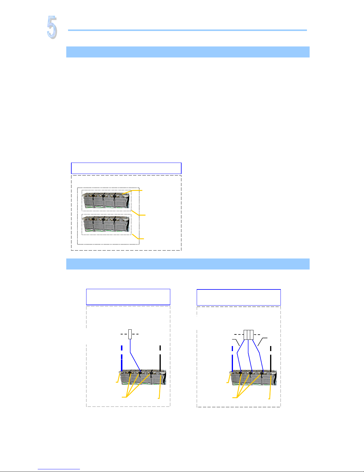
Battery Monitoring
o Battery Terminology (12)
o Battery Symmetry – Connections (12 )
Alarms & Monitoring
o Fail-Safe Operation ⎯ Alarm Relays & Digital Inputs (13 )
o Terminals & Pin-out Location, Alarm Card 100350 (13 )
o Terminals & Pin-out Location, Front Access Alarm Card 101825 (14 )
Introduction
o The Flatpack Product Range (2 )
o Brief System Description (2 )
Installation
o Installing Rectifier Modules and MCU Controller ( 3)
o Installation steps; mechanical, electrical (4-5)
Commissioning
o Pre-start check (6 )
o Commissioning steps, Startup (6-7)
Operation
o Front keys and display ( 8)
o Software Menus ( 8)
Check Lists
pullout forms
o Installation Check List
o Circuit Distribution List
o Commissioning Procedure
o Maintenance Procedure
Page 2
Quick Start Guide Flatpack PS System
356803.103, v4-2006-10
2
The Flatpack Product Range
Eltek Energy's Flatpack product range utilizes the Flatpack rectifier and the MCU controller as
building blocks for implementing effective DC power systems, suitable for a wide range of
applications and power ratings.
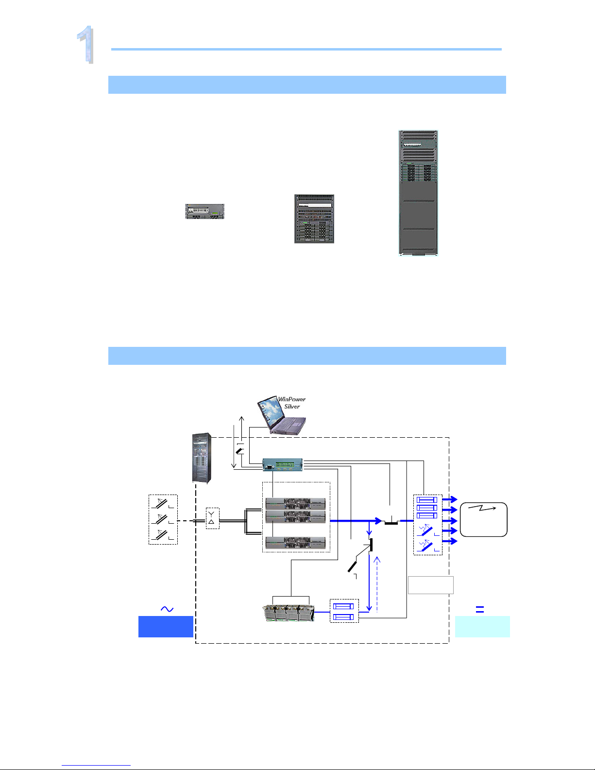
MPSU systems consist of the power system, which includes rectifiers and controller(s), and the
distribution unit (1U or 4U high). MPSU systems are sold primarily for mounting in existing
cabinets.
In PRS systems, the cabinet contains the power system and the distribution unit. In addition, the
cabinet may also enclose battery banks, additional distribution and other dedicated equipment.
Brief System Description ⎯ Flatpack
The Flatpack PS system is a compact, powerful and cost-effective DC power supply system,
specifically developed for the telecom industry.
Example of a typical Flatpack PS system for DC power supply of telecom equipment. The system is fed
from an external AC mains supply, and consists of rectifiers in power shelves, a control unit and DC
distribution unit. Battery banks, LVD contactors, etc. are typically also a part of the system.
Introduction
Flatpac
k
PRSB
Battery string #1
Flatpack MCU
(Ctrl. Unit)
Flatpack
(rectifiers)
A
C mains
supply
selector
Symmetry
Alarm &
Temp. Senso
r
LVLD
LVBD
AC Suppl y
(Single- or
three-
p
hase
)
Fuse Alarm
DC Supply
(24V, 48V
or 60V
)
AC Fuses,
external
(230VAC or
400VAC
Telecom
equipment
A
larm Outputs NC-C-NO
Digital Inputs
DC
distribution
Batte
r
y
Fuses
Load Fuses
& MCBs
Service
S
witch
+/-
MPSU
Modular Power Supply Unit
PRSV
Power Rack System
Wall-mounted
PRSB
Power Rack System
with or without Batteries
Page 3

Quick Start Guide Flatpack PS System
356803.103, v4-2006-10
3
Installing Rectifier Modules and MCU Controller
Installation
Handel in locked position
Hole to release the
handle’s spring mechanism
Flatpac
k
Handel in
unlocked position
Flatpack
Device
hazard
CAUTION:
- The modules may be warm, but do not hand-carry them by their handles
- Open the handles before inserting them into the power shelves
Mounting Flatpack rectifier modules
1. Open the handles by
inserting a screwdriver into the holes to release the spring
mechanism
2. Insert the module fully into the power shelf, so that it makes
proper contact
3. Lock the handles by
pushing the handles up into their housings (locked position),
so that the module makes proper contact and is secured locked
Removing Flatpack rectifier modules
1. Open the handles by
inserting a screwdriver into the holes to release the spring
mechanism
2. Remove the module
using both handles to pull the module loose; support from
underneath
3. Lock the handles by
pushing the handles up into their housings (locked position). It
is then ready for transport
4. Mount blind panels in
unused module locations
Electric
shock
Mounting and Removing the MCU Controller
Note that cables are plugged to the MCU’s rear panel. When
mounting the controller, you must plug the cables before step 2.
When removing it, unplug the cables during step 2.
1. Unlock the controller by
unscrewing the two fastening screws on the front
2. Insert or remove the module by
sliding it fully into the power shelf
or
using both handles to pull the controller loose. Unplug the
cables, when removing the MCU module
3. Lock the controller by
screwing the two fastening screws on the front. It is then
securely locked in the shelf. Or ensure the screws do not fall
out of the holes, when removing the MCU module
Handle
Fastening
holes
MCU Controller
Page 4
Quick Start Guide Flatpack PS System
356803.103, v4-2006-10
4
Installation Steps
Check off in the Installation Check List, that you find in the pullout section o
f
this folder. Also, refer to the system’s specific drawings.
For external AC fuses and AC input cable ratings, refer to your site’s AC
supply specification. Read also our external AC fuse recommendations
in section “Miscellaneous”. In general, a site with better AC supply
quality (stable nominal voltage) may use smaller breakers.
200 mm
600 mm
Flatpack PRS, batteries, Doc.
Chart, Spec. Drawings, CD-ROM
Installation
Preparing the installation site
Begin preparing the following:
1 Organize the installation site
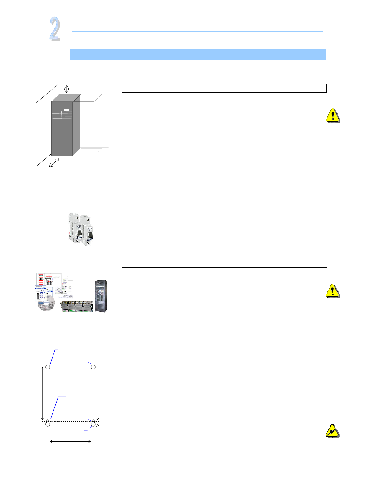
o Min. clearances for cabinet access: 60 cm in front, 20 cm on top
o Levelled surface able to support 600 kg (PRSB),100 kg (PRSV)
o Explosive atmospheres are to be avoided. Ensure suitable
ventilation
o 60V systems are only to be installed in Restricted Access
Locations (RAL)
2 Prepare the installation tools
o Use insulated tools suitable for telecom installations
3 Prepare AC Supply: AC input cable(s) and fuses
o Correct type AC supply is available
o External AC fuses have correct rating
o AC input cable(s) are sized correctly
EMC
regard
Electric
shock
Mechanical Installation
Power is OFF!
Carry out the following:
4 Remove packaging and check equipment
o Check you have received all the parts, correct cabinet,
documentation, batteries (if applicable), etc.
o Inspect the equipment for physical damage (report any damages)
o Leave rectifier modules in their packaging or in the selves, if
factory installed. To be installed under commissioning
5 Remove top cover and dummy front panels
o Cable entry from the top. Connection terminals are located behind
the upper dummy panels
o Battery shelves (if any) are placed behind the lower panels
6 Position and fasten the cabinet or subassembly
o PRSB cabinets are floor-mounted on levelled surface. Adjust the
legs if necessary. If the cabinet must be fastened, unscrew the legs
and use suitable bolts to fasten it to the floor
o PRSV cabinets are wall-mounted; keyholes facilitate fixing
o MPSU subassemblies are fastened in existing 19” or in ETSI
cabinets, using brackets. Mount the support & heat deflecting
plate under the lower power shelf
7 Mount the batteries on the shelves
o Start (if applicable) placing the batteries on the lower shelf first,
and continue upwards
o Do not terminate the battery cables yet!
Device
hazard
Upper
fastening hole
Ø 7 mm
Ø 13 mm
550 mm
Ø 7.3 mm
10 mm
736.7 mm
Lower
fastening hole
Wall-mounting distances
PRSV cabinets
Page 5

Quick Start Guide Flatpack PS System
356803.103, v4-2006-10
5
Electrical Installation
Power is OFF!
Carry out the following: (Refer to the system’s specific drawings)
8 Make the system completely voltage free
o Switch OFF or remove all load fuses (MCB1, MCBx), battery
fuses (Fb1, Fbx) and the AC supply fuses, in external fuse
boards
9 AC Connections
o Check AC configuration: the AC terminals are correct configured
to the external AC supply, otherwise reconfigure the terminals
o Connect the AC Earth wire (PE) to the terminals AC Earth (PE)
o Connect the AC input cable(s) to the terminals. Cable and
terminal block labeling are to correspond
10 DC Connections ⎯ Load Circuits
o Terminate DC Earth (TE), and check that the common DC
Output Rail is connected to “Telecom Earth” (TE) at only one
place (at the cabinet or at a central distribution point). Se
chapter about AC, DC earthing systems
o For each DC load, connect one of the cables to the common DC
output rail, and the other directly to the MCB or load fuse
11 DC Connections ⎯ Alarm & Signal Circuits
o Refer to your system’s connection drawings and configuration
(Factory Settings), or to the “Miscellaneous, Alarms &
Monitoring” section
o Terminate Alarm Circuit cables to the relay output terminals
o Terminate Signal Circuit cables to the digital input/output
terminals
12 DC Connections ⎯ Battery Cables
Careful! Use correct polarity.
For each battery shelf: (refer to the figure in this page)
(In PRS systems, steps b, d and f are usually performed in factory)
a Mount 3 intercell links to connect in series 4 battery blocks
b-c Connect battery cables to fuses and common DC rail, and to
the shelf’s outer terminals; black (+); blue (-)
d-e Connect battery symmetry cables, if applicable, to the input
terminals, and to the center terminal of the battery string
(+). Deviation from factory settings requires Symmetry
reconfiguration via WinPower Silver
f-g Connect the temperature sensor cable, if applicable, to the
input terminals, and fix the temperature sensor (at the end
of the cable) to a suitable place in the middle of the
installed battery bank
Electric
shock
Installation
Block1
- + + - + - + -
Block4Block3
—
(-48V) Oute
r
Terminal
+
0V Outer
Terminal
Link 2
(DC Earth)
Common
DC Rail
EG
Chassis
Battery
Fuse
Intercell Links
Batter
y
Cable
Symmetry cable
Tem
p
. senso
r
Card Art.100986
CON4:11
…and
CON3:3435-36
Temp. Sensor cable
Page 6

Quick Start Guide Flatpack PS System
356803.103, v4-2006-10
6
The commissioning of a Flatpack PS System consists of following stages:
I. Perform a pre-start check before the PS system is switched ON
II. Switch ON the system with disconnected load; adjust output voltage
III. Adjust the nominal output voltage with connected batteries and load
Pre-Start Check
Power is OFF!
Check off in the Commissioning Procedure, that you find in the pullout section of this folder.
If you have just finished the system installation successfully and filled in the Installation
Check List, jump over the Pre-Start Check and continue with stage II.
Before you switch ON the Flatpack PS system, verify the following:
1. System installation is completed
o Ensure a correctly performed system installation, with correct polarity on all
connections, has been carried out (Installation Check List filled in)
o All cabling and copper bars are securely terminated and supported
o All components, terminal blocks, MCBs/ fuses, etc. are clearly labeled
2. Battery and load fuses are disconnected
o Verify that all battery and load MCBs/ fuses are switched OFF or removed
3. AC input cable(s) and AC Earth wire (PE) are terminated
o Make sure that the AC input cable(s) are connected to correctly configured AC terminals
o Verify that the AC input cable(s) and external AC fuses are sized and rated as specified
o Check that AC Earth (PE) is terminated, and electrically connected to chassis (Link 1)
4. Site specific parameters and settings are known
o Read the system specific drawings and documentation
5. AC supply and all MCBs, fuses are switched OFF
o Make sure that all external AC fuses and internal MCBs/ fuses are switched OFF
Commissioning Steps, Startup
Check off in the Commissioning Procedure, that you find in the pullout section of this folder.
After the ”Pre-start Check” is performed, you can begin with stage II. During the stage, you
will switch ON the Flatpack PSS — while the batteries and load are disconnected ⎯ then
measure the output voltage, and adjust it if required. Carry out the following:
Startup and No-Load Adjustments
Power is ON!
1. Disconnect all rectifier modules, without removing them
o Read how to install modules, on page 3 in this guide. and then
o If Flatpack rectifier modules are installed, unlock the handles and pull the modules
partially out (fan housing visible), but do NOT physically remove them from the
power shelves
o If Flatpack rectifier modules are not yet mounted, release their handles and insert
them partially into the shelves
2. Switch ON the system
o Switch ON the AC input supply (external AC fuses) to the PS cabinet
3. Measure and verify that the AC input voltage is correct
o Measure the AC input voltage at the cabinet’s mains connection box
o Verify the AC voltage is within range
Commissioning
Device
hazard
Device
hazard
I
II
Page 7
Quick Start Guide Flatpack PS System
356803.103, v4-2006-10
7
4. Mount all Flatpack rectifier modules in the power shelves
o Push all rectifiers firmly inwards ⎯ one module at a time, allowing a 2s delay ⎯
to plug them in the shelf. Lock their handles. Refer also to page 3 in this guide
o Mount blanking panels over unused positions
5. Ensure that the MCU controller and all rectifier modules are working: LEDs are ON
o Verify correct operation, by monitoring the modules’ LED lamps and display:
No alarms are present on rectifiers; The MCU controller displays fuse alarms
6. Connect a PC to the PS system (to facilitate operation)
o Plug the correct serial cable between the PC and the MCU controller
o Start WinPower Silver on the PC (click on Start>All Programs>Eltek>WinPower Silver)
o Configure equal communication parameters on the MCU and the PC.
Refer to chapter “
Installing WinPower Silver ⎯ PC Application
”, page 9, if required
7. Measure and adjust DC output voltage
o Read the DC output voltage on the controller’s display
o With a multi-meter, measure the DC output voltage at the most accessible point, e.g.
between the common DC rail and the lower connection of one of the priority load MCBs
o If required, adjust the voltage using the controller’s front keys or via WinPower Silver
8. Verify the alarm relays are working correctly (alarm relay test)
o Run the alarm relay test using the controller’s front keys (refer to page 8) or via
WinPower Silver (click the “General Information” button; then the “Relay Test” tab)
9. Make sure the System Setup is in accordance with configuration
o Verify system settings using the controller’s front keys or via WinPower Silver
o Use the opportunity to enter site related information, type of batteries, etc. (Click
the “General Information” button; then the “Site Information” tab)
Load Adjustments
Power is ON!
Now, you can begin with stage III, where you will adjust again the output voltage to the
battery voltage, and connect the batteries and the load. Carry out the following:
10. Adjust DC output voltage to equal measured battery voltage
o Measure the battery voltage is within range (check connections have correct polarity)
o Adjust DC output voltage — using the controller’s front keys (refer to page 8) or via
WinPower Silver— to equal the measured battery voltage.
(Important adjustment to avoid arcing when connecting the batteries)
11. Unplug all rectifiers but one, and connect the battery fuses /MCBs
(CAUTION: Have only one rectifier connected, when switching ON the battery fuses.
Thus, avoiding damaging all rectifiers, due to possible incorrect polarity connections, etc.)
o Disconnect all rectifiers but one, by unlocking the handles and pulling them partially
out (fan housing visible). Do NOT physically remove them from the power shelves
o Switch ON all battery fuses or MCBs
12. Adjust DC output voltage again to equal the nominal battery voltage
o Adjust DC output voltage — using the MCU’s front keys or via WinPower Silver — to
equal the nominal battery voltage (or the nominal load voltage, when not using batteries)
13. Plug in again all rectifiers, and verify the rectifiers’ current sharing
o Connect all rectifiers again by pushing them firmly inwards ⎯ Repeat step 4, in stage II
o Wait for about 2 min., and check — reading the LED bar graph on the rectifiers’ font
panel — that each of the rectifiers delivers the same output current. A ±5 % deviation is
acceptable. (Each LED represents 3A approx.)
14. Connect the load breakers and verify that no alarms are displayed
o Switch ON all load MCBs/ fuses
o Verify correct operation: rectifiers and controller display no alarms
Commissioning
Device
hazard
Device
hazard
III
Page 8
Quick Start Guide Flatpack PS System
356803.103, v4-2006-10
8
Firmware 402080.009 5v1
Service menu <ServiceOption>
Password= 0003
English
German
Norwegian
Language Polish
French
Spanish
p
Comm
Protocol Trace *
Comli
9600
Set baud 1200
2400
4800
MODEM sense MODEM sense: ON
MODEM sense: OFF
* “Trace” is for internal factory use
Level 2 Level 3
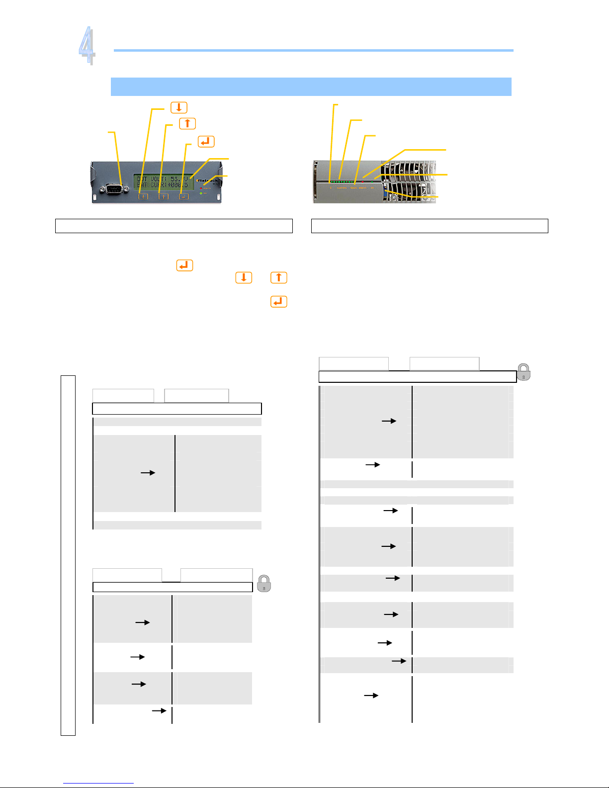
Front Keys and display, menus, etc.
Flatpack rectifier module — front panel, left side
Power LED is OFF (mains unavailable) or ON
(powered). Alarm LED is ON (shutdown or similar
major alarm) or OFF (OK, no alarm)
Output voltage is factory adjusted on delivery. In
stand-alone operation (MCU ctrl. unit is not used),
you can use the potentiometer to adjust the output
voltage.
MCU Control Unit — front keys, display, etc
Display: is in Status Mode (displays the system’s
status) or in Menu Mode (displays the menu structure).
Operation: Press on the
key to change from
Status Mode to Menu Mode. Press the
or
keys to scroll up or down and navigate to find menu
options (function or parameter). Press then the
key to select the function.
Menus: When you “enter” Menu Mode, you access
the User Options. You may also scroll down to
password protected Service Options. Default password
<0000> and <0003> should be changed.
Software Menus
LED bar graph
Output current scale, 10 green LEDs (3A each)
0A scale mark
Alarm
LED Lamp (red)
Power
LED Lamp (green)
30A scale mark
Potentiomete
r
Output voltage adjustment
Flatpack rectifie
r
RS232C
D-Sub 9 pins
female
LCD displa
y
Alarm
LED Lamp (red)
”Up” arrow key
”Down” arrow key
”Enter” key
MCU control unit
Service menu <ServiceOption>
Password= 0000
NomVolt
BoostVolt
LowBatt1
LowBatt2
V
oltAdjustment HighBatt1
HighBatt2
LVD 1
LVD 2
LVD 3
Calibration VoltCal
SetDefaultCalib.
ChangePassword Æ Password
SetBoostTime Æ BoostTime
Start/StopBoost Æ StartBoost/StopBoost
Auto Boost Cfg. Enable/Disable
Threshold
IntervalTest Date Time
Test End Volt
Batt Test Setup Max Test Duration
Test Interval
Test Delay Period
Start/Stop Test Æ Start Test/Stop Test
Charge Curr Lim Enable/Disable
Max Charge Curr
Battery Setup Æ Number of banks
Number of rectifiers
Capacity Al.Cfg. Current pr rectifier
Alarm limit
Temp.Comp
OutputControl Voltage Control
Presat Rect.Volt
Change Date/Time Date
Time
Relay1
Relays 2…10
Relay Test Relay 11
LVD1 relay
LVD2 relay
LVD3 relay
Level 2
Level 3
Firmware 402080.009 5v1
User menu <UserOption>
System ON/OFF Æ Turn system ON/OFF *
Alarm Reset Æ Alarm Reset
NomVolt
BoostVolt
LowBatt1
LowBatt2
VoltageInfo HighBatt1
HighBatt2
LVD 1
LVD 2
LVD 3
DisplayMessages Æ Display messages
Sw Info Æ SwInfo
* The ON/OFF function may be disabled in some
systems
Level 2 Level 3
Firmware 402080.009 5v1
Operation
Keys & Menus
Page 9

PULLOUT
Check Lists Pullout
Pull out the pages with the gray outer band,
and use them as check lists
Page 10
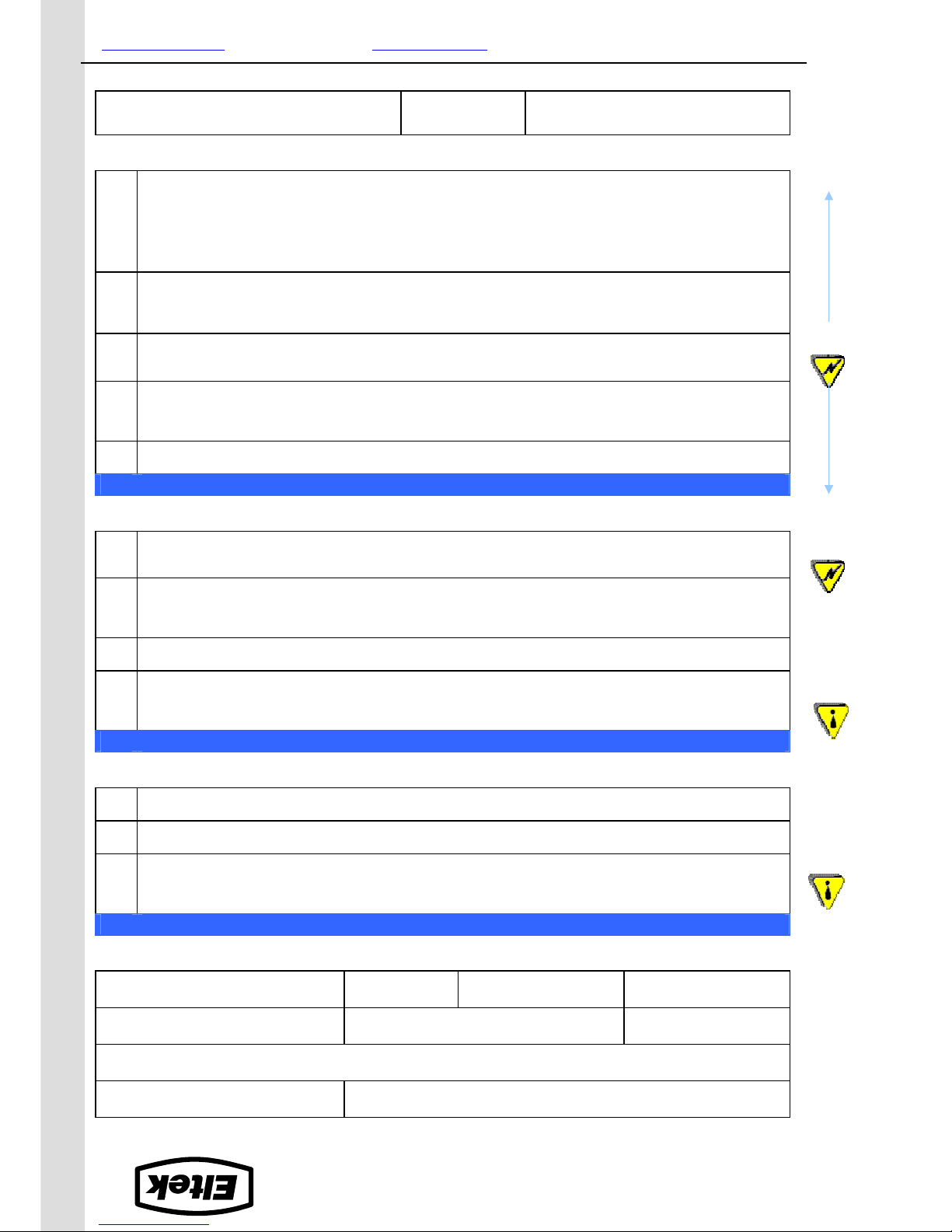
INSTALLATION CHECK LIST
System Data
Flatpack PS System
Flatpack Power Supply System, type: Article No.:
Site, name:
Serial No.: Software, version No.: Rectifiers, type & number of:
AC Input Voltage, measured: Battery Type: Battery Capacity: Installation carried out by, name:
Site Preparations
CARRY OUT FOLLOWING
:
OK
1. Organize the installation site
o Check min. clearances for cabinet access: front access, 60cm, top access, 20cm
o Check that the levelled surface is able to support 600 kg (PRSB systems), 100 kg (PRSV systems)
o Ensure the installation site is suitably ventilated and in a non-explosive atmosphere. 60V systems in RAL areas
2. Prepare the installation tools
o Check that insulated tools suitable for telecom installations are used
3. Prepare AC Supply: AC input cable(s) and fuses
o Check the AC supply is the correct type, and that the external AC fuses and AC input cable(s) are suitably rated
Mechanical Installation
Power is OFF!
CARRY OUT FOLLOWING
:
OK
4. Remove packaging and check equipment
o Check you have received all the parts, correct cabinet, documentation, batteries (if applicable), etc
o Inspect the equipment for physical damage (report any damages)
o Leave rectifier modules in their packaging or in the selves, if factory installed. (commissioning task)
5. Remove top cover and dummy front panels
o Check that cable entry from the top is possible
6. Position and fasten the cabinet or subassembly
o PRSB cabinets on levelled surface, adjust the legs. If necessary, unscrew the legs and fasten the cabinet to floor
o PRSV cabinets are wall-mounted. Keyholes facilitate fixing
o MPSU subassemblies in existing 19” or in ETSI cabinets, using brackets. Mount support & heat deflecting plate
7. Mount the batteries on the shelves
o Start (if applicable) on the lower shelf first, and continue upwards
o Do not terminate the battery cables yet!
Electrical Installation
Power is OFF!
CARRY OUT FOLLOWING
:
OK
8. Make the system completely voltage free
o Switch OFF or remove all load fuses (MCB1, MCBx), battery fuses (Fb1, Fbx) and external AC supply fuses
9. AC Connections
o Check AC configuration: The AC terminals are correct configured to the external AC supply
o Connect the AC Earth wire (PE) to the terminals AC Earth (PE)
o Connect the AC input cable(s) to the terminals. Cable and terminal block labeling are to correspond
10. DC Connections ⎯ Load Circuits
o Terminate DC Earth (TE):
Common DC Output Rail is connected to TE at only one place
o For each DC load, connect one of the cables to the common DC output rail, and the other directly to the MCB
11. DC Connections ⎯ Alarm & Signal Circuits
o Refer to your system’s connection drawings and configuration, or to the Factory Settings in the Quick Start Guide
o Terminate Alarm Circuit cables to the relay output terminals
o Terminate Signal Circuit cables to the digital input/output terminals
12. DC Connections ⎯ Battery Cables Careful! Use correct polarity.
For each battery shelf,
o Mount 3 intercell links to connect in series 4 battery blocks
o Connect battery cables to fuses and common DC rail, and to the shelf’s outer terminals; black (+); blue (-)
o Connect battery symmetry cables, if applicable, to the input terminals, and to the battery string
o Connect the temperature sensor cable, if applicable, to the input terminal, and fix the sensor (at the end of the
cable) to a suitable place in the middle of the installed battery bank
Approval
Responsible of installation, sign.: Date: Approved by customer, sign.:
EMC
regard
Electric
shock
Device
hazard
Electric
shock
Form XXX-gb-v1-C01_356803-103_qstart_flatpack-pss.doc_mfm_2006-10-11
Eltek Energy AS
Tel. +47 32 20 32 00
Page 11
Form 165-gb-v3-C01_356803-103_qstart_flatpack-pss.doc_mfm_2006-10-11
Eltek Energy AS
Tel. +47 32 20 32 00
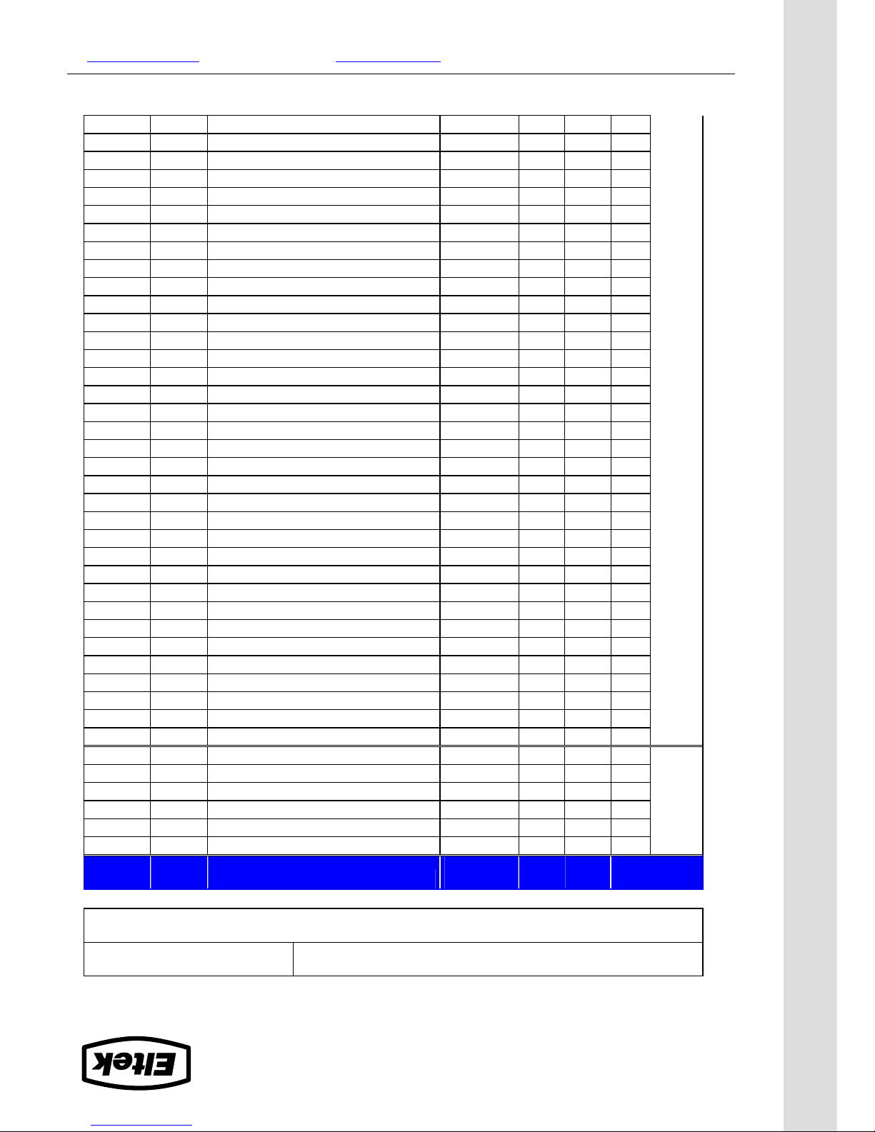
CIRCUIT DISTRIBUTION LIST
System Data
Flatpack Power Supply System, type: Article No.:
Site, name:
CIRC
.
NO
.
FUSE
KNIFE
TYPE
MCB
LVLD
CONTROLLED
DESCRIPTION
FUSE
AMPERE
CABLE
mm
2
Fb1
Fb2
Fb3
Fb4
Fb5
Fb6
F1
F2
F3
F4
F5
1.
2.
3.
4.
5.
6.
7.
8.
9.
10.
11.
12.
13.
14.
15.
16.
17.
18.
19.
20.
21.
22.
23.
24.
25.
26.
27.
28.
29.
30.
Continue
LOAD
BATT.
Page 12

CIRCUIT DISTRIBUTION LIST
CIRC
.
NO
.
FUSE
KNIFE
TYPE
MCB
LVLD
CONTROLLED
DESCRIPTION
FUSE
AMPERE
CABLE
mm
2
31.
32.
33.
34.
35.
36.
37.
38.
39.
40.
41.
42.
43.
44.
45.
46.
47.
48.
49.
50.
51.
52.
53.
54.
55.
56.
57.
58.
59.
60.
61.
62.
63.
64.
65.
66.
LOAD
Form 165-gb-v3-C01_356803-103_qstart_flatpack-pss.doc_mfm_2006-10-11
Eltek Energy AS
Tel. +47 32 20 32 00
Page 13
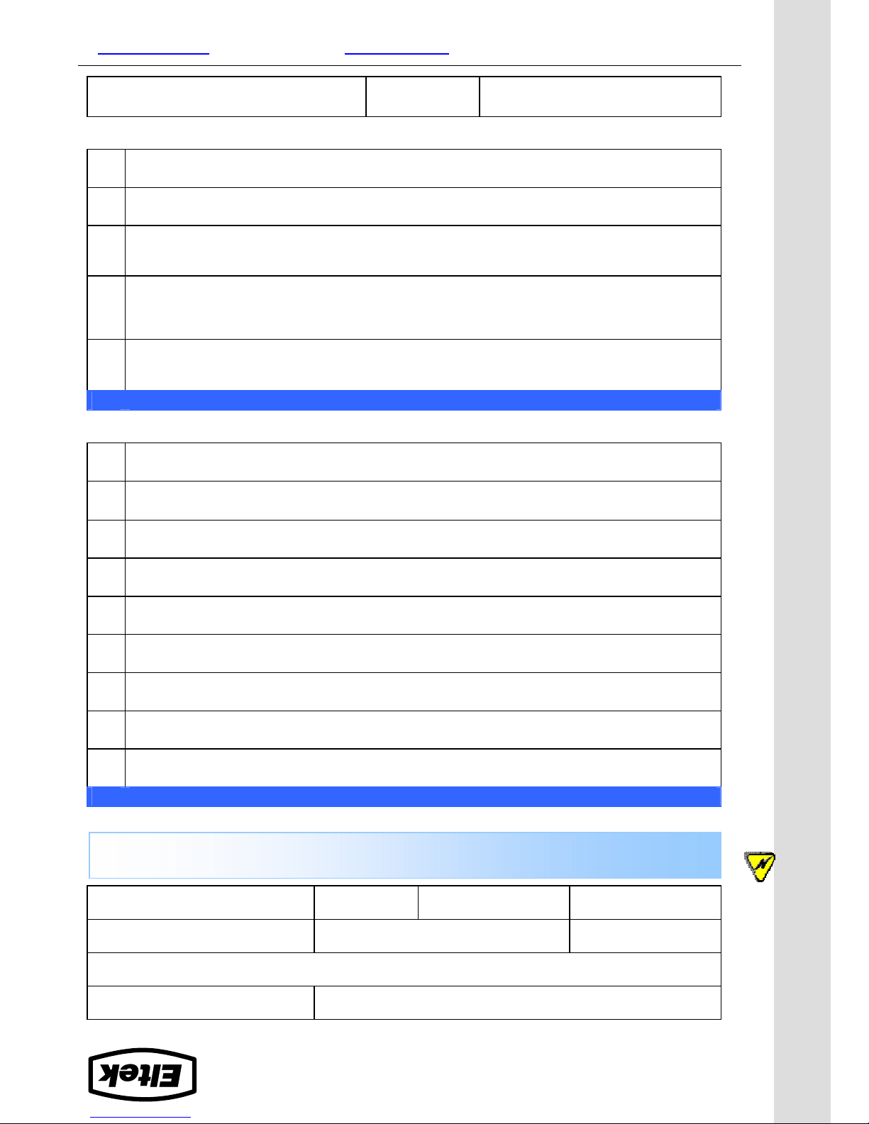
MAINTENANCE PROCEDURE
System Data
Flatpack PS System
Flatpack Power Supply System, type: Article No.:
Site, name:
Serial No.: Software, version No.: Rectifiers, type & number of:
AC Input Voltage, measured: Battery Type: Battery Capacity: Maintenance carried out by, name:
System Inspection
Power is ON!
CARRY OUT FOLLOWING
:
OK
1. Site specific parameters and settings are known.
User manuals and site specific connection & arrangement drawings are available.
2. The battery bank has been fully charged in advance.
At least for 12 hours since start-up or mains failure. Enables correct measurements & calibration
3. The equipment is free from damage, dust or dirt; verify.
Carefully vacuum clean or remove any accumulation of dust, corrosion or dirt.
4. All cabling and copper bars are securely terminated and supported.
Correct any loose connections, excessive cable temperature, defective insulation, etc.
5. The MCU & all rectifier modules are ON, no alarm present; verify.
Otherwise, correct and put the PS system in normal mode of operation.
6. All rectifier’s functionality & MCU’s keys and display work OK; verify
Correct possible abnormalities before continuing.
7. Connect the PS system to a PC (install the WinPower Silver application if required)
The WinPower Silver program in the PC enables system configuration from the PC.
8. Rectifiers’ load current sharing; verify.
The number of LEDs illuminated on every rectifier's bar graph should be equal (±1 LED).
9. Display the stored log of Alarm Messages.
Using the keypad on the MCU controller or from the PC.
System Adjustment
Activate the Service Switch, if installed
CARRY OUT FOLLOWING
:
OK
1. DC Output Voltage Calibration; ensure correct display readings.
If measured DC output voltage at the load terminals deviates more than ±1% from the display reading, calibrate the
output voltage from the MCU’s keypad or the PC.
2. Load & Battery Current Calibration; verify correct display readings.
Measure with a clip-on ammeter the battery current & every load circuit current. Calculate the total load & battery
current. If the calculated total values deviate more than ±1% from the display readings, calibrate the current from the
PC (calibration value>50% of system’s max. capacity)
3. DC Output Voltage Adjustment; measure and adjust.
Measure and, if required, adjust the output voltage to the nominal voltage recommended by the battery manufacturer.
(Voltage measurements to be done at the DC rail, with little load current)
4. Alarm Relay Test; verify all alarm relays are working correctly.
From the MCU’s keypad or PC use the Relay Test function; verify activation of external equipment
5. Battery bank control; measure and verify battery specifications.
Follow the recommendations of the actual battery manufacturer.
Approval
Responsible of maintenance control, sign.: Date: Approved by customer, sign.:
WARNING: Maintenance work on live equipment is only to be performed by authorized and
qualified persons using insulated tools. Hazardous voltages inside may cause terminal injury.
Electric
shock
Form 166-gb-v2-C01_356803-103_qstart_flatpack-pss.doc_mfm_2006-10-11
Eltek Energy AS
Tel. +47 32 20 32 00
Page 14

PULLOUT
Page 15
Form 164-gb-v3-C01_356803-103_qstart_flatpack-pss.doc_mfm_2006-10-11
Eltek Energy AS
Tel. +47 32 20 32 00
COMMISSIONING PROCEDURE
System Data
Flatpack PS System
Supplier’s Order No.: Flatpack Power Supply System, type: Article No.:
Site, name:
Serial No.: Software, version No.: Rectifiers, type & number of:
AC Input Voltage, measured: Battery Type: Battery Capacity: Commissioning carried out by, name:
Pre-Start Check
Power is OFF!
CHECK FOLLOWING
:
OK
1.
Flatpack system installation is completed;
The Flatpack Installation Check List is filled in.
All cabling is securely terminated with correct polarity
2. All battery and load MCBs/ fuses are disconnected
3. AC input cable(s) and AC earth wire (PE) are terminated
4. Site specific parameters and settings are known
5. AC supply and all MCBs/ fuses are switched OFF
Start-up, No-Load & Load Adjustments
Power is ON!
CARRY OUT FOLLOWING
:
OK
1. Disconnect all rectifier modules, without removing them
2. Switch ON the system (external AC fuses ON)
3. AC input voltage is correct;
Measure and verify
4. Insert all Flatpack rectifiers in their locations in the power shelves
5. The MCU and all rectifier modules are working, LEDs are ON;
Verify
6. Connect a PC to the PS system
Install the WinPower Silver program, if required
7. DC output voltage;
Measure and adjust
8. Alarm relay test;
Verify all alarm relays are working correctly
9. System Setup is in accordance with configuration
Enter site spec. info in WinPower Silver
10. Adjust DC output voltage to equal measured battery voltage
Check correct polarity!
11. Unplug all rectifiers but one, and connect all battery fuses/ MCBs
12. Adjust DC output voltage to equal nominal battery or load voltage
13. Plug in again all rectifiers, and verify the rectifiers’ current sharing
14. Connect all load MCBs/ fuses, and verify no alarms are displayed
Approval
Responsible of commissioning, sign.: Date: Approved by customer, sign.:
Device
hazard
I
II
Device
hazard
III
Device
hazard
Page 16

PULLOUT
Check Lists Pullout
Pull out the pages with the gray outer band,
and use them as check lists
Page 17
Quick Start Guide Flatpack PS System
356803.103, v4-2006-10
9
Installing WinPower Silver ⎯ PC Application
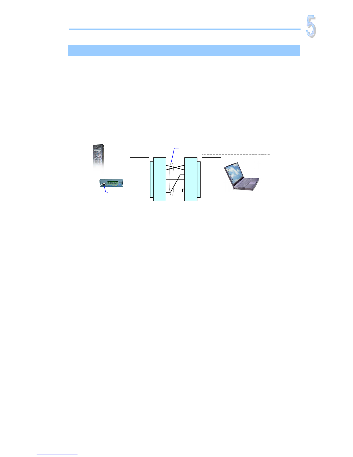
WinPower Silver software enables you to configure and operate the Flatpack PSS from a
personal computer.
Installation
1. Connect the MCU’s D-Sub to one of the PC’s COM port using an RS232C serial cable
2. Install WinPower Silver in the PC
3. Verify that MCU and PC have equal communication parameters,
e.g.: 9600 baud, 8b, P=N, Sb=1
MCU
Control Unit
Control Room
Technical Room
RS232C serial cable, 9—9 pins
Max. 15m, RS232 driver protocol
D-SubD-Sub
9 pins (female)
9 pins (male)
1
2
3
4
5
6
7
8
9
1
2
3
4
5
6
7
8
9
COM1, D-Sub
9 pins (female)
COMx, D-Sub
9
p
ins
(
male
)
RxD
TxD
GND
RxD
TxD
GND
CTS
DTR
Flatpack PRS
D-Sub
WinPower
Silver
PC
Communication
Miscellaneous
Page 18
Quick Start Guide Flatpack PS System
356803.103, v4-2006-10
10
External AC Fuses ⎯ Recommended Rating
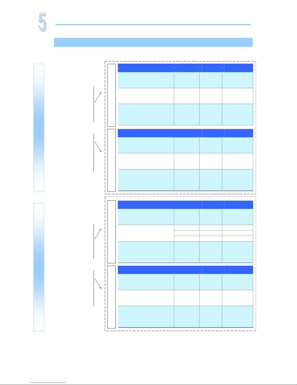
The site’s AC supply quality is of great importance. In general, a site with better AC supply
quality (stable nominal voltage) may use smaller breakers.
Miscellaneous
AC Mains
* The calculation for single sub-rack configuration requires separate AC feed to each module position
Note: The above recommendations apply for use of Thermal magnetic circuit breaker, type Siemens 5SX or 5SY series, MG C60H
series or similar. For more information regarding External AC fuses and other types of fuses, please read the article 2014385 for
Flatpack 1500 systems or the article 2014386 for Flatpack 1800 systems on the CD, 356802.CD3.
AC Mains No of Power Current Ext. Fuse
Type Shelves Max. (A) Type (Th/Mag)
1
16.2
25A-C
2
32.4
40A-C
230VAC
1-phase
3
48.6
50A-C
1*
8.1
25A-C
2 or 3
16.2
25A-C
230/400VAC
3-phase, TN network
(5 wire system)
4,5 or 6
32.4
40A-C
1*
14.0
25A-C
2 or 3
28.1
32A-C
4
42.9
50A-C
230VAC
3-phase, IT network
(4 wire system)
5 or 6
56.1
63A-C
AC Mains No of Power Current Ext. Fuse
Type Shelves Max. (A) Type (Th/Mag)
1
18.1
25A-C
2
36.1
40A-C
230VAC
1-phase
3
54.2
63A-C
1*
9.0
25A-C
2 or 3
18.1
25A-C
230/400VAC
3-phase, TN network
(5 wire system)
4,5 or 6
36.1
40A-C
1*
15.6
25A-C
2 or 3
31.3
32A-C
4
47.8
50A-C
230VAC
3-phase, IT network
(4 wire system)
5 or 6
62.6
63A-C
205VAC Inputs 185VAC Inputs
Flatpack 1500
For Flatpack 1500 systems use the recommendations in the
205VAC table, if you
are sure the available
AC mains voltage will
not drop below
205VAC.
OR
If you are unsure ⎯ or
know that the voltage
may drop below
205VAC ⎯ use the
185VAC table recommendations.
Doc 2014385, v2
AC Mains No of Power Current Ext. Fuse
Type Shelves Max. (A) Type (Th/Mag)
1
19.5
25A-D
2
39.0
40A-C
230VAC
1-phase
3
58.5
63A-C
1*
9.8
25A-D
2 or 3
19.5
25A-D
230/400VAC
3-phase, TN network
(5 wire system)
4,5 or 6
39.0
40A-C
1*
16.9
25A-D
2 or 3
33.8
40A-C
4
51.6
63A-C
230VAC
3-phase, IT network
(4 wire system)
5 or 6
67.6
80A-C
For Flatpack 1800 systems use the recommendations in the
205VAC table, if you
are sure the available
AC mains voltage will
not drop below
205VAC.
OR
If you are unsure ⎯ or
know that the voltage
may drop below
205VAC ⎯ use the
185VAC table recommendations.
Doc 2014386, v2
AC Mains No of Power Current Ext. Fuse
Type Shelves Max. (A) Type (Th/Mag)
1
21.7
25A-D
2
43.5
50A-C
230VAC
1-phase
3
65.2
80A-C
1*
10.9
25A-D
2 or 3
21.7
25A-D
230/400VAC
3-phase, TN network
(5 wire system)
4,5 or 6
43.5
50A-C
1*
18.8
25A-D
2 or 3
37.7
40A-C
4
57.5
63A-C
230VAC
3-phase, IT network
(4 wire system)
5 or 6
75.3
80A-C
205VAC Inputs 185VAC Inputs
Flatpack 1800
Page 19
Quick Start Guide Flatpack PS System
356803.103, v4-2006-10
11
About AC, DC Earthing Systems
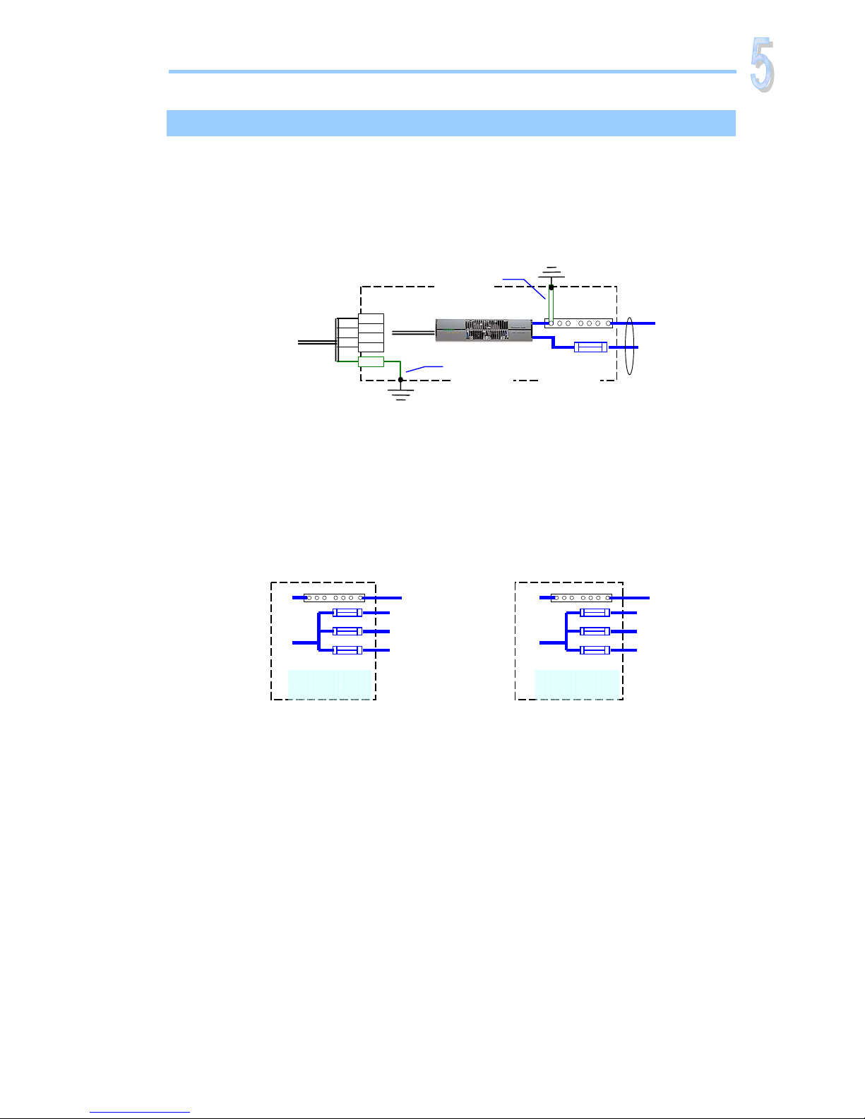
To prevent the risk of electric shock, all cabinet’s chassis are to be electrically connected to AC
Earth (PE). Also, it is a common practice for telecom equipment to have its common DC output
rail (+ or -) connected to a separate “Telecom Earth” (TE) or DC Earth.
Earth connections are in particular important where frequent lightning might induce high
voltage levels in AC supply and in battery and load cables.
AC Earth (PE) and DC Earth (TE) are usually connected to chassis via “Link 1” and “Link 2”.
Remove the links (“floating earth”) for compliance with other local earthing systems. Refer to
your system’s specific drawings to identify how these links are implemented in your DC power
system.
Common Positive DC Output Rail is usual in 48 and 60V DC supply systems: Negative DC
Distribution. Common Negative DC Output Rail is usual in 24V systems: Positive DC
Distribution.
Earthing
Miscellaneous
Cabinet
PE
A
C Mains
Common
DC Rail
EG
.
A
C Mains Input
(L1,L2,L3,N)
DC Load
Circuit
Link 2
(DC Earth)
Link 1
(AC Earth)
TE
Chassis
Chassis
PE (Protective Earth)
TE (Telecom Earth)
EG (Exchange Ground)
Common DC Rail —
DC Load
wires
+
+
+
+
Positive DC
Distribution
—
—
—
Negative DC
Distribution
Common DC Rail +
DC Load
wires
Page 20
Quick Start Guide Flatpack PS System
356803.103, v4-2006-10
12
Battery Terminology
Refer to your system’s specific drawings for the exact connection points.
Symmetry measurement is a battery monitoring method of automatically detecting
unbalanced battery blocks. Symmetry monitoring of a battery string may be performed by
measuring each battery block (block measurement method), or by only measuring the midpoint of the battery string (mid-point measurement method).
The mid-point measurement method requires one symmetry cable per battery string, while the
block measurement method requires 3 symmetry cables per battery string.
Flatpack PRSB systems are delivered with the symmetry measurement method and the
number measurement points already preprogrammed in the MCU module. Any deviation from
factory settings requires Symmetry reconfiguration via PC and WinPower Silver.
Battery Symmetry Connections
The examples below show battery symmetry connections for 48V DC supply systems.
Battery Terminology
Battery Block, Battery String and Battery Bank
48V Battery Bank
Batter
y
String #1
(48V)
Batter
y
Block (12V)
Batter
y
String #2
(48V)
Battery Symmetry
Mid-point Measurement
One measurement per string
—
(-48V) Oute
r
Terminal
+
0V Oute
r
Terminal
Intercell Links
11
CON4
+
Front access
circuit card
100986
Symmetry
cable 1
Battery Symmetry
Block Measurement
Three measurements per string
—
(-48V) Oute
r
Terminal
+
0V Outer
Terminal
Intercell Links
CON4
+
Front access
circuit card
100986
+ +
11
12
13
Symmetry
cable 1
Symmetry
cable 3
Example of a 48V battery bank implemented
with two 48V battery strings; each string
consists of four 12V battery blocks.
Normally, battery banks are implemented
by connecting in parallel several battery
strings; each string is formed by battery
blocks connected in series.
Miscellaneous
Battery Monitoring
Page 21
Quick Start Guide Flatpack PS System
356803.103, v4-2006-10
13
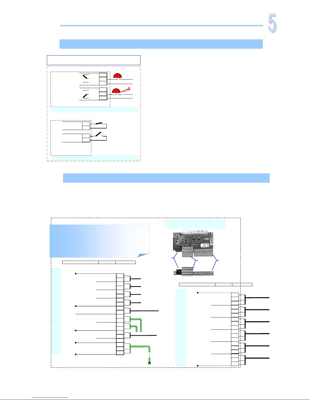
Fail-Safe Operation ⎯ Alarm Relays & Digital Inputs
The alarm outputs in Flatpack systems use the FailSafe Operation Mode (relay coils energized in the
system’s normal operation mode). When the system is
in alarm mode, the alarm relay coils are de-energized.
The figure shows the position of the relay contacts
when the relay coils are de-energized (PS system in
alarm mode)
In order to implement monitored fail-safe digital
inputs circuits, the external relay coil must be
energized and the contacts closed in the system’s
normal mode of operation.
Terminals & Pin-out Location, Alarm Card 100350
DC power systems using the Alarm & Signal Interface Card ⎯ Art. 100350, basic version ⎯
have following alarm outputs and monitoring inputs available: 6 alarm relay outputs, 4 digital
inputs, 3 symmetry alarm inputs and 1 temperature sense input.
For detailed information about the card’s pin-out location and terminal block connections,
refer to the figure in this section.
Standard Relays & Digital Inputs
Correct Use of Digital Inputs (example)
Normal Mode
External Relay Y
(Energized coil)
+
—
Digital Input X
(Normal mode)
A
larm Mode
External Relay Y
(De-energized coil)
+
—
Digital Input X
(Activated)
Flatpack PS System
Correct Use of Alarm Outputs (example)
Flatpack PS System
—
+
NC
NO
Com
Normal Mode
Relay X
(Energized coil)
+
—
A
larm Mode
Relay X
(De-energized coil)
NC
NO
Com
The figure shows the position of the relay
contacts when the PS system is in its alarm
mode of operation. The relay coils are then
de-energized (fail-safe mode). The relay
outputs are preprogrammed from factory
(Factory Settings).
Terminals & Pin-out Location
Alarm & Signal Card, Art. 100350
CON2*
CON3*
CON2*
1 10
11 20
1 18
CON5
CON4
1
12
CON5
6
5
4
3
2
1
9
7
12
11
10
15
14
13
18
17
16
8
NC
NO
Com
NC
NO
Com
NC
NO
Com
NC
NO
Com
NC
NO
Com
NC
NO
Com
Relay 6
Common Alarm
Relay 5
Module Alarm
Relay 4
Fuse Alarm,
Load & Battery
Relay 3
Low Battery Alarm
Relay 2
High Battery Alarm
Relay 1
Mains Alarm
Alarm Relay Outputs
Voltage free (circuit card 100350)
A
larm Circuit 1
A
larm Circuit 2
A
larm Circuit 3
A
larm Circuit 4
A
larm Circuit 5
A
larm Circuit 6
FUNCTION SIGNAL PIN-OUT
1.
5
mm
2
, max. wire section
Symmetry Alarm 2
(digital input)
Symmetry Alarm 3
(
Not used)
+21V Auxiliary Supply
200mA (for external equipment)
6
5
4
3
2
CON4
1
+
9
8
7
12
11
10
15
14
13
18
17
16
20
19
—
screen
Monitoring Input Signals
Digital & Analogue Inputs (circuit card 100350)
Analogue
Inputs
Temperature Sense
(for internal battery bank)
+
—
(To Modem)
+
—
Symmetry Alarm 1
+
—
+
AGND
(From external Symmetry
A
larm circuit card, art. 26851)
Digital Input 4
+
AGND
Digital Input 3
+
AGND
Digital Input 2
+
+
AGND
(From external equipment)
**
FUNCTION SIGNAL PIN-OUT
(From area with
internal batteries)
Temperature
senso
r
(F
r
om
internal
batteries)
1.5 mm2, max.
wire section
* CON2 & CON3 are used for internal connections (connected from factory)
** For correct use of digital inputs, see the Fail-Safe Operation chapter
A
larms & Monitorin
g
Miscellaneous
Page 22
Quick Start Guide Flatpack PS System
356803.103, v4-2006-10
14
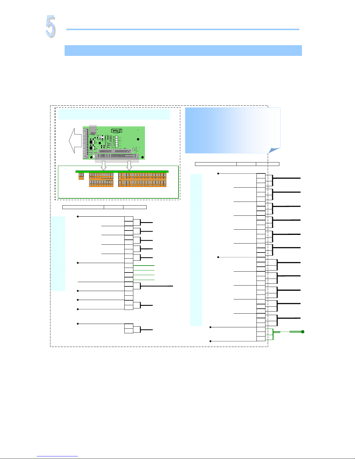
Terminals & Pin-out Location, Alarm Card 101825
DC power systems using the front access Alarm & Signal Interface Card (Art. 101825) have
following alarm outputs and monitoring inputs available: 11 alarm relay outputs, 5 digital
inputs, 5 symmetry alarm inputs and 1 temperature sense input.
For detailed information about the card’s pin-out location and terminal block connections,
refer to the figure in this section.
Miscellaneous
Alarms & Monitoring
Terminals & Pin-out Location
Alarm & Signal Front Access Kit, Art. 101825
Circuit Card 100985
Internal System
Connections,
CON1
1
CON3
Customer Connections (front access, circuit card 100986)
1
1
2
10
1120
118
1936
CON4
CON5
The figure shows the position of the
relay contacts when the PS system
is in its alarm mode of operation.
The relay coils are then deenergized (fail-safe mode). The
relay outputs are preprogrammed
from factory (Factory Settings).
6
5
4
3
2
CON3
1
9
8
7
12
11
10
15
14
13
18
17
16
24
23
22
21
20
19
27
25
30
29
28
33
32
31
36
35
34
26
NO
Com
NC
Relay 7
(not programmed)
A
larm Circuit 11
Alarm Relay Outputs
Voltage free (Front access circuit card 100986)
FUNCTION SIGNAL PIN-OUT
+
—
screen
Temperature Sense
(for external battery bank)
(From area
with external
batteries)
Temperatu
r
e
senso
r
NO
Com
NC
NO
Com
NC
NO
Com
NC
NO
Com
NC
NO
Com
NC
A
larm Circuit 1
A
larm Circuit 2
A
larm Circuit 3
A
larm Circuit 4
A
larm Circuit 5
A
larm Circuit 6
Relay 6
Common Alarm
Relay 5
Module Alarm
Relay 4
Fuse Alarm,
Load & Battery
Relay 3
Low Battery Alarm
Relay 2
High Battery Alarm
Relay 1
Mains Alarm
NO
Com
NC
Relay 8
(not programmed)
NO
Com
NC
Relay 9
(not programmed)
NO
Com
NC
Relay 10
(not programmed)
NO
Com
NC
Relay 11
(not programmed)
NO
Com
NC
A
larm Circuit 10
A
larm Circuit 9
A
larm Circuit 8
A
larm Circuit 7
1.
5
mm
2
, max. wire section
2
CON5
1
+
—Auxiliary Supply
System output voltage
(for external equipment)
(To external
equipment)
1.5mm2, max.
wire section
FUNCTION SIGNAL PIN-OUT
Symmetry Alarm 5
(digital input)
(
Not used
)
6
5
4
3
2
CON4
1
+
9
8
7
12
11
10
15
14
13
18
17
16
20
19
—
Monitoring Input Signals
Digital & Analogue Inputs
(Front access circuit card 100986)
Analogue
Inputs
(To Modem)
+
Symmetry Alarm 1
+
+
AGND
(From external
Symmetry Alarm circuit
card, art. 26851
)
Digital Input 4
+
AGND
Digital Input 3
+
AGND
Digital Input 2
+
AGND
Digital Input 1
+
AGND
(From external equipment)
**
(From
external
batteries)
+21V Auxiliary Suppl
y
200mA (for external equipment)
(
Not used
)
+
+
Symmetry Alarm 2
Symmetry Alarm 3
Symmetry Alarm 4
Digital Input 5
+
AGND
1.5 mm2, max. wire section
* CON1 is used for internal connections (connected from factory)
** For correct use of digital inputs, see the Fail-Safe Operation chapter
Page 23

Quick Start Guide Flatpack PS System
356803.103, v4-2006-10
15
Page 24

Head Office
Eltek Energy AS
PO Box 2340 Strømsø; N-3003 Drammen; Norway
Tel:+47 32 20 32 00 — Fax:+47 32 20 32 10
E-mail: [email protected]
Internet: www.eltekenergy.com
Copyright © Eltek Energy AS, Norway 2006
This document may be changed without notice
Doc. No. 356803.103, Issue 4, 2006 Oct
Published 2006-10-11
This product is CE marked and
complies with all current requirements
for relevant standards and directives.
 Loading...