


p
o
2
O
5
c
0
r
d
d
a
a
P
2
l
r
t
u
W
m
e
Dis
BC
lay
00
Ope
an
atio
JC2
n M
000
nua
Con
roll
rs
C
mpa
Part No. D
60000023
t, Inte
grate
, HJ,
DC
nd J F
ower
Doc. No.
Pu
ont
Syste
055882, Iss
blished 20-J
ire
s
5.1
ue
n-14

a
n
e
a
r
o
.
d
e
e
a
s
o
h
t
8
u
i
s
n
s
t
o
y
u
C
0
b
a
e
s
y
u
c
5
n
+
h
8
p
w
0
a
r
f
u
n
n
0
k
0
3
0
p
8
t
o
o
t
t
o
r
2
t
n
i
e
s
r
p
e
u
r
e
e
u
DISCL
Inform
to cha
either
compa
While
Eltek
attribu
No pa
electr
expres
AIMER
tion in this
ge without
a commitm
tibility of th
very reason
ssumes no
ted to the u
t of this d
nic or mec
sed consen
ocument is
notice. Thi
nt or any g
products a
ble effort i
responsibili
e of the inf
cument ma
anical, incl
of Eltek.
believed to
document
uarantee on
d procedur
made to en
y or liabilit
rmation con
be reprod
ding photo
opyright
292
Pla
Phone:
Fax: +1
Tec
+1 (
techsup
w
e accurate
nd the info
the part o
s described.
ure the acc
for any da
tained withi
ced or tra
opying and
© 2010-2
E Plano P
o, TX 75
USA
1 (469) 3
(469) 33
nical Sup
00) 435-4
ort.us@el
w.eltek.c
s of the da
mation con
Eltek regar
uracy and c
mages that
or to any e
smitted in
recording—
14 Eltek
wy
74
0-9100
-9101
ort
872
ek.com
m
e of publica
ained herei
ding the rel
mpleteness
may be dir
rors or omis
any form o
for any pur
ion and is s
do not rep
ability, fitn
of this docu
ctly or indi
ions.
by any m
ose witho
bject
esent
ss, or
ment,
rectly
ans—
t the
Doc
2
Publ
No. 2055
ished 20 J
82, Issue
ne 2014
Display Operat
5.1, June
on Manual BC2
014
00 and JC200
Controller ~ D
c. No. 205588
, Issue 5.1, Jun
2014

Table of Contents
1. Overview .......................................................................................... 5
Display Screen ...................................................................................................................... 5
Status Indicators ................................................................................................................. 7
Navigation Buttons ............................................................................................................. 7
Audible Alarm ....................................................................................................................... 7
Controller Connections ...................................................................................................... 7
References .......................................................................................................................... 10
2. Controller Installation and Setup .................................................. 11
Basic Installation ................................................................................................................ 11
Controller Input Ports ....................................................................................................... 12
Controller Settings ............................................................................................................ 14
3. Viewing Information (Login Not Required) .................................... 15
Home Screen Information ................................................................................................ 15
Screen Saver ....................................................................................................................... 17
Main Menu............................................................................................................................ 18
View Shunt Current ........................................................................................................... 19
View Individual Rectifier Output Current ..................................................................... 19
View Firmware Version ..................................................................................................... 19
View IP Address .................................................................................................................. 19
4. Settings and Configuration (Login Required) ................................ 20
Change System Time and System Date ...................................................................... 21
Shunt Setup ........................................................................................................................ 21
Input Port Setup ................................................................................................................. 21
Change Float Voltage ....................................................................................................... 22
Generator Setup ................................................................................................................ 22
Restore Preset ................................................................................................................... 23
Change Temperature Units ............................................................................................. 24
Run Relay Test ................................................................................................................... 24
Change Audible Alarm ...................................................................................................... 24
Change Beep Volume ....................................................................................................... 24
Change Screen Saver Settings ...................................................................................... 25
Ringers .................................................................................................................................. 25
5. Battery Features (Login Required) ................................................ 26
Battery Current Limit ........................................................................................................ 26
Battery Discharge Test .................................................................................................... 26
Boost Mode ......................................................................................................................... 27
Over Temperature ............................................................................................................. 28
Temperature Compensation ........................................................................................... 29
Thermal Runaway .............................................................................................................. 30
6. Basic Troubleshooting ................................................................... 31
Display Operation Manual BC2000 and JC2000 Controller ~ Doc. No. 2055882, Issue 5.1, June 2014 3

Appendix – Parameter Settings and Ranges ........................................ 35
Appendix – Controller Menu Trees ....................................................... 41
System ................................................................................................................................. 44
Alarming ............................................................................................................................... 45
Modules ................................................................................................................................ 46
Activate ................................................................................................................................ 48
Battery Management ....................................................................................................... 49
Generator ............................................................................................................................. 50
Thermal ................................................................................................................................ 51
Probes, Network, and Display ......................................................................................... 53
Version and Presets .......................................................................................................... 54
Revision Table ....................................................................................... 55
4 Display Operation Manual BC2000 and JC2000 Controller ~ Doc. No. 2055882, Issue 5.1, June 2014

1. Overview
This manual supplements the Compact, Integrated, HJ Systems (BC2000 controller)
and J Front Wire System (JC2000 controller) installation manuals. It covers the
connections and front display operations of the BC2000/JC2000 controllers. For
information on the remote interface consult the Web Interface Manual
BC2000/JC2000 Controller, Doc. No. 2056625.
The controller provides microprocessor-based control over all plant functions,
serves as an aggregation point for all alarm and monitoring data, and provides
remote and local communications and user interface. Each System plant requires
just one BC2000/JC2000 controller equipped with a display.
• BC2000 Controller: Compact, Integrated, and HJ “Mini” Systems
• JC2000 Controller: J Front Wire (JFW) Systems
NOTE: This document revision (Issue 5.1) is based on controller firmware version
4.02.10 and display firmware version 7.02.10. Subsequent versions may include
minor changes to available features and/or menus.
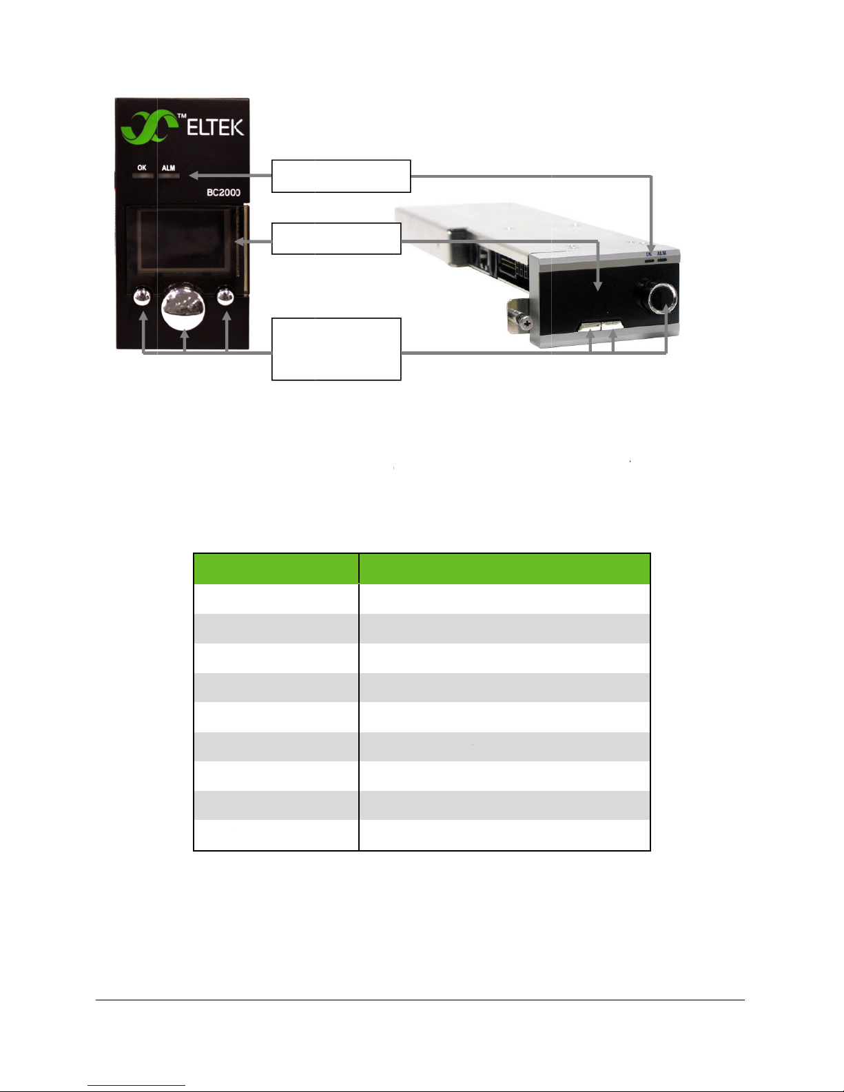
Display Screen
The display consists of an advanced backlit OLED screen, one scroll knob, two
buttons, two LEDs, and an audible alarm buzzer. This display is the user interface
for all system communication devices, such as low voltage disconnect (LVD) and
peripheral monitors (PM).
Display Operation Manual BC2000 and JC2000 Controller ~ Doc. No. 2055882, Issue 5.1, June 2014 5
0
p
i
r
r
n
t
e
d
E
E
M
R
E
N
E
W
i
u
e
e
M
O
obutsc
u
0
r
e
h
r
m
e
u
w
s
0
o
o
h
i
n
A
t
m
e
o
d
g
o
C
y
p
t
e
m
t
p
m
2
o
a
s
T
v
e
t
BC20
0 Controlle
Stat
Disp
C
s indicator
lay section
ntroller
tons and
roll knob
J
2000 Contr
ller
The dis
voltage
status,
knob to
which a
lay scree
on the lef
nternal te
view thes
e detaile
Messa
SYST
SYST
T CO
BATT
BATT
BATT
UNK
is divided
and outp
peratur
messag
in Table 1
ge
M OK
M ALARM
P
ECHRG
BOOST
RY TEST
OWN SYSTE
Figu
in two pa
t current
, date, tim
pages. T
.
Table 1 –
Desc
Nor
Any
Tem
Batt
Batt
Batt
No r
re 1 – Contr
ts. The t
on the rig
and prof
e first line
Controller D
iption
al Operatio
larm condi
perature Co
ery Recharg
ery Boost m
ery Discharg
ctifiers are
ller Displa
p part dis
t. The par
le on thre
displays s
isplay
(no alarms)
ion
pensation
mode is ac
de is active
e Test is in
detected.
lays prim
below di
pages.
ystem sta
ode is acti
ive.
.
rogress.
ry plant
plays sys
urn the sc
tus messa
e.
em
roll
ges,
SYST
M CHANGE
FIRM
ARE DOWNL
6
Display Operat
Mod
AD Firm
on Manual BC2
le has been
are is bein
00 and JC200
added or re
upgraded
Controller ~ D
oved.
c. No. 205588
, Issue 5.1, Jun
2014

Status Indicators
The display unit has green (OK) and red (ALM) LEDs. The green LED is always ON
when the controller is powered, unless a system alarm is present. When a system
alarm is present the red LED turns ON.
Navigation Buttons
The display has one scroll knob and two buttons for navigating controller menus:
◄ (Left Button) is used to go back or abort
► (Right Button) is used to go forward or apply
(Scroll Knob) is used to scroll up or down in the menus or change the values
NOTE: All scroll knob directions in this document assume a clockwise turn, which
scrolls downward through pages and menus, and increments numerical values.
Audible Alarm
The display unit has an audible alarm located in the rear. When an audible alarm is
present, press left or right button to silence the alarm sound.
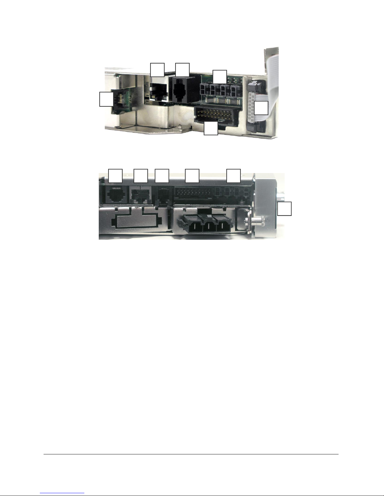
Controller Connections
The controller has the following connections:
1. CAN – Communicates with external Eltek Peripheral Monitoring Device
PM86001 or PM86000.
2. LAN – Accepts an Ethernet cable for browser-based interface (see
DOCUMENT)
3. I2C – Communication connection to external Eltek distributions
4. Temp/Aux – Input ports that accept temperature probes and/or dry-contact
relays
5. Alarm Relay – Form-C output alarm relays (requires Eltek cable, sold
separately)
6. Display – Connection for the controller display
Display Operation Manual BC2000 and JC2000 Controller ~ Doc. No. 2055882, Issue 5.1, June 2014 7
2 3
4
1
6
5
Figure 2 - BC2000 Controller Connections
3 2 1 4
5
6
Figure 3 - Controller Connections (JC2000)
CAN Bus
The controller is equipped with one Controller Area Network (CAN) bus port for
connecting peripheral monitors (PM). PM devices provide additional alarm I/O to the
BC2000. The controller can support up to 8 daisy-chained devices. For more
information, consult the PM86001 Peripheral Monitor Installation Guide, Doc. No.
370015.033.
Alarm Cable Connection
Six form C alarm relays are provided through a connector labeled “Alarm Relay” (see
Figure 2). To access these alarms, use the cable assembly (sold separately) that
has the mating 20-pin Molex connector on one end and bare tinned wire on the
other. Available alarm cable part numbers are CA210203104 (10ft), CA210203105
(50ft), and CA210203106 (100ft). Plug the cable connector into the “Alarm Relay”
connector on the controller. As for the end with bare wire, there are three wires for
each relay providing both normally open (NO) and normally closed (NC) alarm
functionality. See Table 2 for the color code for each alarm channel (relay). Select
the proper alarm type and connect the cables to the alarming equipment.
8 Display Operation Manual BC2000 and JC2000 Controller ~ Doc. No. 2055882, Issue 5.1, June 2014

NOTE: The alarm names in Table 2 are based on the default controller with profile
number 01 (e.g., 1A01-10VC). Refer to the instructions for determining the
controller’s profile number in the section “Profile and Preset” on page 16 to
determine the controller’s profile number. A relay test can be used to verify that
the alarm cable is connected properly. See details on page 24.
Table 2- Alarm Cable Color Code
Alarm Relay Designation Wire Color Description
NC Orange/White Stripe Contact Opens on Alarm
A
B
C
D
E
C Orange Common
NO Orange/Black Stripe Contact Closes on Alarm
NC Red/White Stripe Contact Opens on Alarm
C Red Common
NO Red/Black Stripe Contact Closes on Alarm
NC Green/White Stripe Contact Opens on Alarm
C Green Common
NO Green/Black Stripe Contact Closes on Alarm
NC Yellow/Stripe Contact Opens on Alarm
C Yellow Common
NO Yellow/Black Stripe Contact Closes on Alarm
NC Light Blue/White Stripe Contact Opens on Alarm
C Light Blue Common
NO Light Blue/Black Stripe Contact Closes on Alarm
NC Tan/White Stripe Contact Opens on Alarm
F
NO Tan Common
NC Tan/Black Stripe Contact Closes on Alarm
Alarms can be mapped to the output relays. The default relay map is shown in Table
3 on page 31. These relays can be customized through the web interface. For
additional details on mapping alarms, refer to the Web Interface Manual
BC2000/JC2000 Controller, Doc. No. 2056625.
Display Operation Manual BC2000 and JC2000 Controller ~ Doc. No. 2055882, Issue 5.1, June 2014 9

LAN Connection
A local area network (LAN) connection is available for communication with a
computer using the controller GUI interface. For further information on how to
connect to and use the Ethernet LAN port, refer to the Web Interface Manual
BC2000/JC2000 Controller, Doc. No. 2056625. Communication with the LAN port is
through an Ethernet cross-over cable or straight-through cable to a router. This
cable is not supplied by Eltek. The controller can be connected to a LAN or directly
to a PC. Ethernet cables are not supplied by Eltek.
Controller Inputs
The controller has four (4) two-pin input connections that can accept either an Eltek
temperature probe or an auxiliary alarm input. Due to the inherent properties of the
thermistor in the temperature probes the controller will automatically adjust the
input configuration for a temperature reading.
NOTE: Controller alarm circuits are rated for a maximum voltage of 60VDC and
maximum current of 0.5A.
I2C Bus
The controller is equipped with one Inter-Integrated Circuit (I2C) bus port for
connecting to rectifier shelves and LVD cards. All necessary connections are made
at the factory. This I2C bus is for a second shelf and LVD.
References
Information regarding other interfaces and features of the BC2000 and JC2000
controllers can be found in the following documents
• Web Interface Manual BC2000/JC2000 Controller, Doc. No. 2056625
• PM86000 Installation Guide, Doc. No. 2040334
• PM86001 Peripheral Monitor Installation Guide, Doc. No. 370015.033
• BC2000 Diesel Generator Interface Guide, Doc. No. 2040334
• BC2000 Controller Firmware Update, Document No. 2061910
10 Display Operation Manual BC2000 and JC2000 Controller ~ Doc. No. 2055882, Issue 5.1, June 2014

o
2
t
e
c
a
A
C
W
a
A
C
B
l
r
-
W
l
o
e
o
i
E
a
e
0
o
e
o
i
E
0
t
s
o
o
e
n
f
n
f
~
o
c
e
e
o
l
c
o
a
D
l
o
l
c
8
d
r
2
t
e
a
w
t
p
E
r
m
c
s
m
c
s
p
s
m
a
t
m
a
1
u
g
t
s
g
t
2. C
The BC
Integra
with Elt
Basi
To inst
1.
2. G
3.
ntrol
000 cont
ed, and H
k J Front
Instal
ll a BC200
lign the c
ently slid
If
the contr
a
nd try aga
AUTION:
p
ermanentl
ith the ch
a
nd rock th
er Ins
oller is de
J series p
ire DC p
ation
0 controll
ntroller in
it into the
ller does
n.
xcessive
y damagin
ssis conn
top back
allati
igned spe
wer shelv
wer shelv
r into an E
the contr
shelf unti
ot conne
orce can b
g the cont
ected, ho
until it sn
n an
ifically fo
s. The JC
s.
ltek DC po
ller slot.
it connec
t properly
end or bre
roller.
k the bott
ps in plac
Setu
use with
000 cont
wer syste
s to the b
to the ba
ak the pin
om of the
.
Eltek Com
oller is de
:
ackplane.
kplane, si
of the re
display in
act,
igned for
ply reali
r connec
he chassi
se
n
or,
To inst
Display Ope
1.
2. G
If
a
p
ll a JC200
lign the c
ently slid
the contr
nd try aga
AUTION:
ermanentl
ration Manual
controlle
ntroller in
it into the
ller does
n.
xcessive
y damagin
C2000 and JC2
Figure 4 –
r into an E
the contr
shelf unti
ot conne
orce can b
g the cont
00 Controller
isplay Inst
tek DC po
ller slot.
it connec
t properly
end or bre
roller.
Doc. No. 2055
llation
er syste
s to the b
to the ba
ak the pin
82, Issue 5.1, J
:
ackplane.
kplane, si
of the re
une 2014
ply reali
r connec
n
or,
1
W
r
a
A
e
o
m
t
d
e
a
e
n
s
e
y
u
p
p
t
r
e
i
o
o
s
e
gFig
n
u
n
m
0
o
a
t
e
M
s
a
n
i
m
0
e
o
t
s
s
a
T
i
A
P
o
t
t
a
m
r
e
o
2
t
o
a
e
e
s
e
e
u
3.
ith the ch
a
nd rock th
ssis conn
top back
ected, ho
until it sn
k the bott
ps in plac
om of the
.
display in
he chassi
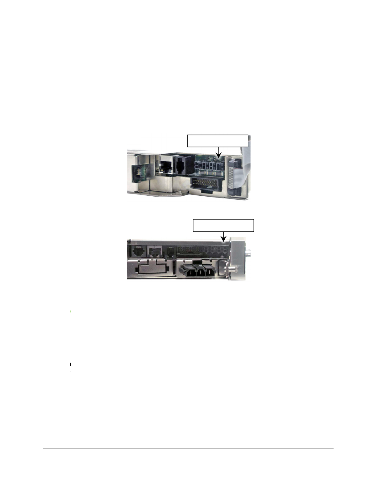
Cont
Use the
and/or
“TEMP/
oller I
direction
uxiliary al
UX” in th
put P
in the foll
rm input
figures b
Fi
rts
wing sec
. There ar
low.
ure 5 – TEM
ions for c
four inpu
TEMP/
P/AUX Port
TEM
nnecting
ports on
UX Ports
(BC2000)
/AUX Ports
emperatu
the contr
re probes
ller, label
d
Temp
Up to f
battery
Temper
the te
instruc
enable
the ext
rature
ur batter
temperat
ture com
perature
ions on se
, the cont
rnal prob
Probe I
temperat
re compe
ensation
robes. Se
ting up th
oller auto
s.
ure 6 – TE
put
re probe
sation fe
must be e
e the sect
ermal co
atically c
P/AUX Port
(sold sep
ture.
abled for
on “Over
pensation
onfigures
(JC2000)
rately) m
the syste
emperatu
. When th
tself to m
y be insta
to take
e” on pag
rmal com
nitor tem
lled for th
dvantage
28 for
pensation
perature
of
is
sing
12
Display Operat
on Manual BC2
00 and JC200
Controller ~ D
c. No. 205588
, Issue 5.1, Jun
2014

c
n
c
n
t
B
P
e
a
a
e
m
P
-
e
n
e
m
0
p
u
t
a
p
u
a
~
r
h
s
e
p
n
r
h
s
n
8
b
r
s
l
b
m
r
p
l
e
t
e
h
n
a
n
1
t
h
Conne
To con
1. C
2. P
3. C
ting a T
ect a TPP-
onnect th
lace the p
b
etween b
b
atteries.
onnect th
P-style
style tem
two-wire
Fig
ddle in be
tteries is
two-wire
tempera
erature p
cable to t
re 7 – TPP-
tween th
ight, the
cable to a
ture pro
obe:
e paddle.
tyle tempe
first and
addle can
ny availab
e
See Figur
ature probe
econd ba
be placed
e TEMP/A
7.
teries. If t
on top or i
UX port o
e space
n front of
the contr
he
oller.
4. R
Conne
To con
1. C
2. P
3. C
4. R
epeat for
ting a T
ect a TPR
onnect th
lace the ri
s
ring.
onnect th
epeat for
ultiple b
R-style
style tem
two-wire
Fig
g termina
two-wire
ultiple b
ttery stri
tempera
erature p
cable to t
re 8 – TPR-
l onto the
cable to a
ttery stri
gs.
ture pro
obe:
e ring ter
tyle tempe
negative
ny availab
gs.
e
inal styl
ature probe
ost of the
e TEMP/A
temperat
second b
UX port o
ure probe.
ttery in t
the contr
e
oller.
Display Ope
ration Manual
C2000 and JC2
00 Controller
Doc. No. 2055
82, Issue 5.1, J
une 2014
3

Controller Settings
The controller is configured with default settings based on the profile number. No
additional setup is required. Default parameter values are listed in Table 5 (page
36). These values represent the default profile (“Profile 01”). Actual profile numbers
vary depending on customer specifications. See the section “Profile and Preset” on
page 16 to determine the controller’s profile number.
If the number is different from the default profile (01), then contact Eltek technical
support at 1-800-435-4872 for a copy of the settings specified by that profile
number.
14 Display Operation Manual BC2000 and JC2000 Controller ~ Doc. No. 2055882, Issue 5.1, June 2014

3. Viewing Information (Login Not Required)
Use the Controller Menu Trees in Appendix A for assistance.
Controller navigation uses three buttons: The scroll button () scrolls up and down
the current menu, while the left (◄) and right (►) buttons navigate backward and
forward, respectively, through the menus. The scroll button () also changes
setpoints, and the right (►) button accepts changes.
NOTE: All scroll knob directions in this document assume a clockwise turn, which
advances downward through pages and menus, and increments numerical values.
Press the left (◄) button repeatedly to return to the home screen.
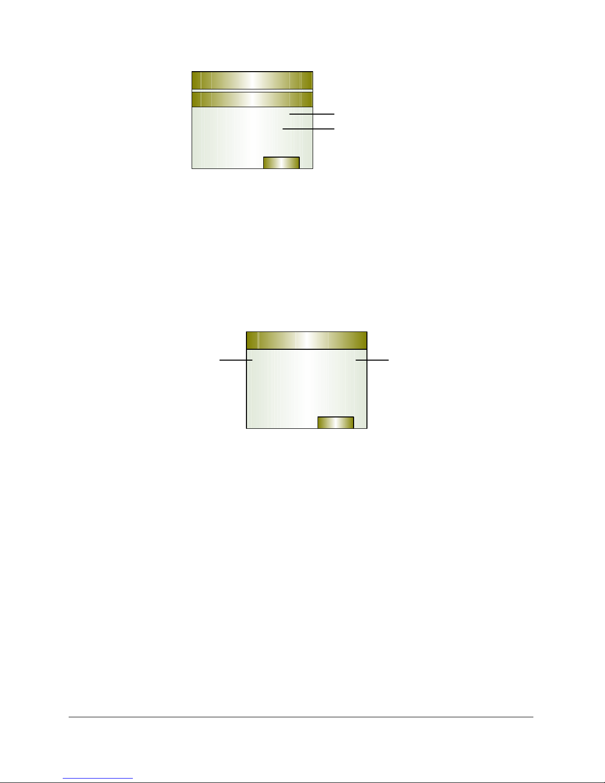
Home Screen Information
There are three pages of information provided on the home screen:
• System status
• Date and time
• System profile and preset
NOTE: If temperature probes are installed, another home screen page appears
between the system status page and the date and time page.
Every page displays the system voltage and output current in the top bar (see
Figure 9).
System Status
The first page to appear on the home screen indicates system status and internal
temperature. If any alarms are triggered, the flashing Alarm tab appears above the
left button.
Display Operation Manual BC2000 and JC2000 Controller ~ Doc. No. 2055882, Issue 5.1, June 2014 15
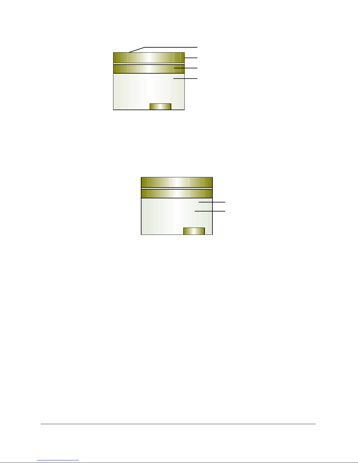
System Voltage
Page 1
54.00V 100A
System OK
Internal 30C
Menu
Figure 9 - Page 1: System Status
Total Rectifier Current
System Status
Internal Temperature
Date and Time
The next page is accessed with a single clockwise turn of the scroll knob. This page
displays the date and time.
Page 2
54.00V 100A
Date & Time
10/12/2006
13:55:32
Date
Clock
Menu
Figure 10 - Page 2: Date and Time
To change the date and time, see the section “Change System Time and System
Date” on page 21.
Profile and Preset
The last page is accessed with another single clockwise turn of the scroll knob. This
page displays the controller profile number and the preset.
Profiles are prescribed settings negotiated with Eltek for custom parameter values
and alarm mappings. The default profile number for 48V systems is “A01”. On the
profile page, this profile is displayed as “1A01-10VC”. The default profile number for
24V systems is “B01”. If a profile number other than A01 or B01 is displayed, then it
is a custom profile.
Presets are subsets of profiles. Up to three presets can be configured for
parameter values only (not alarm mapping). These three presets are typically called
“A”, “B”, and “C”. Preset A is the default preset.
16 Display Operation Manual BC2000 and JC2000 Controller ~ Doc. No. 2055882, Issue 5.1, June 2014
Page 3
54.00V 100A
1A01-10VV
Profile
Preset A
Profile Number (“A01”)
Preset (A, B, or C)
Menu
Figure 11 - Page 3: Profile and Prest
To change the preset, see the section “Restore Preset” on page 23.
Temperature Probes (If Installed)
If temperature probes are installed, the temperature readings for the probes appear
on a home screen page that appears between the system status page and the date
and time page.
54.00V 100A
Temperature
Probe Number
Probe 3 17C
Probe 4 59C
Temperature
Reading
Menu
Figure 12 - Temperature Probe Page (if probes are installed)
Screen Saver
The screen saver serves two purposes:
• Log out of administrative access if the interface is idle for too long
• Prevent screen burn-in from excessive exposure of a single screen image
The timeout period that triggers the screen saver is configurable. Once the timeout
period expires, the system automatically logs out and goes into screen saver mode.
The screen saver shows system voltage and current.
Display Operation Manual BC2000 and JC2000 Controller ~ Doc. No. 2055882, Issue 5.1, June 2014 17

54.00V
Screen Saver
100A
Figure 13 – Screen Saver
To clear the screen saver, push either the right or left button once or turn the scroll
knob one click in either direction.
NOTE: The timeout feature overrides all status notices, including alarms and
temperature compensation. The alarm LED (“ALM”) on the controller faceplate
indicates alarm conditions even if the screen saver is active. Clear the screen saver
to restore the home screen and view status and alarm notices.
To change the screen saver and timeout period, see the section “Change Screen
Saver Settings” on page 25.
System Voltage
Total Rectifier Current
Main Menu
To access the Main Menu from the home screen press the right (►) button. The
following submenus are found in the main menu:
• Login (only appears when no user is logged in)
• System
• Alarming
• Modules
• Activate
• Battery Mgt
• Generator
• Thermal
• Probes
• Network
• Display
• Version
18 Display Operation Manual BC2000 and JC2000 Controller ~ Doc. No. 2055882, Issue 5.1, June 2014

• Presets
• Logout (only appears when a user is logged in)
NOTE: Unless otherwise stated, all navigation directions throughout the rest of this
document begin from the main menu.
View Shunt Current
The controller can read current shunts installed in the system. Shunts interface
with the BC2000/JC2000 controller via LVD cards. LVD cards read a single shunt,
typically for a battery low-voltage disconnect contactor.
LVD devices are considered “Modules” and appear under the “LVD” submenu. To
view the current of LVD modules, follow the steps below:
Main Menu ► Modules ► LVD Card x ► I Shunt x
View Individual Rectifier Output Current
The controller provides information on individual rectifiers installed in the system.
Each rectifier position number depends on the position of the shelf in the I2C
communication daisy chain. Power modules are counted from left to right, starting
with the topmost shelf. To view the output current of a particular module follow
the steps below.
Main Menu ► Modules ► Rectifiers ► S:x Mod:y
View Firmware Version
The controller and display firmware version can be found as follows:
Main Menu ► Version ► Controller
► Display
View IP Address
The controller’s IP address can be found as follows:
Main Menu ► Network ► IP Address
Display Operation Manual BC2000 and JC2000 Controller ~ Doc. No. 2055882, Issue 5.1, June 2014 19

4. Settings and Configuration (Login Required)
Administrator login is required in order to change system settings.
To log into the controller as administrator:
1. From the Main Menu, select “Login”. The message “Enter Pin” appears above a
row of four zeroes (“0000”).
2. Enter the four-digit PIN. The following steps are for the default administrator
PIN (5001):
a. Scroll the first number to “5”.
b. Press the right button three times to highlight the last number.
c. Scroll the last number to “1”. The PIN reads “5001”.
3. Press the right button (“Apply”) to apply the PIN. The message “Admin
Verified” appears briefly before returning to the Main Menu.
It is also possible to login from configurable parameters. If not logged in when
viewing a page with a configurable setting, the tab above the right button reads
“Login”. Press the “Login” button and enter the PIN as described above; then the
configuration page for the parameter appears.
NOTE: If the display interface is left idle for the period specified by the display
timeout setting, the controller automatically logs out and enters screen saver
mode. Once the screen saver is activated, it is necessary to login again to change
controller settings.
NOTE: Admin login from the display overrides all other Admin sessions. For
example, an Admin session via LAN connection is ended when an Admin login
session is started at the display.
All parameters that are configurable through the display are also configurable
through the LAN interface. See the document 2056625 – BC2000/JC2000 LAN
Interface Manual for details.
Refer to the “Appendix – Controller Menu Trees,” which begins on page 41, for
comprehensive menu trees.
20 Display Operation Manual BC2000 and JC2000 Controller ~ Doc. No. 2055882, Issue 5.1, June 2014

Change System Time and System Date
The controller time and date must be set manually to the current time to use such
features as event log and battery discharge scheduling. The time format is
HH:MM:SS (12-hour and 24-hour formats available) and the date format is either
MM/DD/YYYY or DD/MM/YYY.
Main Menu ► System ► Time
► Date
Shunt Setup
Where available, a shunt is monitored by the LVD card that is installed in the
distribution panel. By default, each LVD reads just one shunt.
Main Menu ► Modules ► LVD (if installed) ► LVD Card # ► Contactor #
The following settings are configurable:
• State—set to Open or Closed
• Disconnect V—voltage at which the LVD opens
• Reconnect V—voltage at which the LVD closes
• Recon Delay—time delay after the reconnect voltage is reached before the
LVD contactor closes
Input Port Setup
Use these instructions to setup a controller TEMP/AUX input port as an auxiliary
alarm input. The input port does not need configuration if a temperature probe is
installed.
Main Menu ► Probes ► Probe #
The following are available states:
• Disabled – input port is disabled
• T Probe – the probe input operates as a temperature probe input. This
setting automatically configures itself if an Eltek temperature probe is
installed.
• Aux NO – set the port to monitor a normally open form-C relay.
• Aux NC – set the port to monitor a normally closed form-C relay.
Display Operation Manual BC2000 and JC2000 Controller ~ Doc. No. 2055882, Issue 5.1, June 2014 21

• Dist NO – set the port for external, normally open distribution panel alarms
(e.g., blown fuse or circuit breaker tripped).
• Dist NC – set the port for external, normally closed distribution panel alarms
(e.g., blown fuse or circuit breaker tripped).
Change Float Voltage
The system arrives with a pre-defined float voltage. If it is necessary to change this
voltage setting, use the feature below.
Main Menu ► System ► Float V ► Edit
Minimum: 42V
Maximum: 56V
Generator Setup
The generator interface is designed for systems supported by a diesel generator
that charges batteries and powers the system. Only BC2000 controllers with
controller software version 4.01.30 or higher and display version 7.01.24 or higher
support interface with a diesel generator (go to “Main Menu” and select “Version” to
check controller and display versions).
In order for the diesel generator and the BC2000 controller to interface properly,
three alarm connections are required:
1. The generator must be connected to the form-C output relay “F” (tan-colored
wire set) of the controller alarm cable; use Normally Open (“NO”) and Common
(“C”). See Table 2.
2. A status relay from the AC service panel must be connected to input “T3” on
the controller. This input port (“Probe 3”) should be set to “Auxiliary –
Normally Closed.”
3. A status relay from the diesel generator must be connected to input “T4” on
the controller (far right connector). This input port (“Probe 4”) should be set
to “Auxiliary – Normally Open.”
NOTE: To setup the input ports, refer to the section “Input Port Setup” on page 21.
22 Display Operation Manual BC2000 and JC2000 Controller ~ Doc. No. 2055882, Issue 5.1, June 2014

Form-C Relay
Output
Main Menu ► Generator
The following setpoints are configurable:
• State—enable or disable the generator feature
• Type—select the type of generator: “Air Cooled” or “Other”
• Battery AH—enter the ampere-hour rating of the connected battery string
• DischargeLVL—set the percentage of the battery string’s ampere-hour
capacity at which the generator should turn on and begin recharging the
batteries
Other information available on this page:
• Available AH—real-time calculation of the battery string’s remaining available
ampere-hours
• Available AM—calculation of the battery string’s remaining available ampereminutes
• Available Min—the battery string’s estimated remaining discharge time in
minutes
For further details, including feature behavior, see document 2045453 – BC2000
Diesel Generator Interface Guide.
Restore Preset
The presets are factory values for all parameters shown in Table 5 and the alarm
relay configuration. By default all three presets are identical for profile 01. These
presets can be used to return the system to default settings (requires an
administrator login). Presets are non-adjustable, but custom presets can be
requested through Eltek.
Main Menu ► Preset ► Current ► Edit
Display Operation Manual BC2000 and JC2000 Controller ~ Doc. No. 2055882, Issue 5.1, June 2014 23

Change Temperature Units
By default controller temperature readings are in Celsius. To change temperature
units to Fahrenheit, use the “Temp. Unit” parameter under “System.”
Main Menu ► System ► Temp. Unit
Run Relay Test
This test allows the user to check that the alarm cable has been connected to the
user’s alarm transport equipment properly. See the section “Alarm Cable
Connection” on page 8 for information on the output alarm relays.
Once test mode is enabled each relay can be set to either an active or inactive
alarm state. The relay changes state when activated. To access the relay test
enable feature:
Main Menu ► Activate ► Relays ► Test Mode
To select individual relay states:
Main Menu ► Activate ► Relay X
NOTE: It is recommended to set all relays to inactive once the test is complete.
Change Audible Alarm
The audible alarm can be set for any alarm status (major, minor, or major and minor
or any alarm).
Main Menu ► Alarming ► Audible ► Edit
Change Beep Volume
The beep volume can be adjusted on a scale of 0% to 100% as follows:
Main Menu ► Display ► Beep Volume ► Edit
24 Display Operation Manual BC2000 and JC2000 Controller ~ Doc. No. 2055882, Issue 5.1, June 2014

Change Screen Saver Settings
The timeout period can be adjusted between 1 and 60 minutes as follows:
Main Menu ► Display ► Timeout ► Edit
The screen saver can be changed as follows:
Main Menu ► Display ► Screen Saver ► Edit
Ringers
If ring generators are installed in the system, the following parameters can be
adjusted:
• AC Voltage—AC output voltage
• DC Voltage—DC value at which the ringer RMS value is offset. It should be
equal to the float voltage.
• Frequency—ring frequency
• Select—priority of ring generator module:
None—Disables ring generator
Ringer A—Makes the ring generator the main ringer module
Ringer B—Makes the ring generator the backup ringer module
Other information available on this page:
• Status—ring generator activity status code
• Runtime—total ring generator runtime
• Version—ring generator software version
• Model—module model number
• Serial—module serial number
The ring generator menu is accessed as follows:
Main Menu ► Modules ► Ringers (if installed)
Display Operation Manual BC2000 and JC2000 Controller ~ Doc. No. 2055882, Issue 5.1, June 2014 25

B
n
e
s
W
p
s
e
t
g
r
t
h
M
e
r
t
.
l
y
f
t
a
t
s
n
f
a
e
r
c
e
►
c
g
g
n
i
u
r
t
e
-
e
m
e
e
a
a
t
r
t
e
e
t
0
L
e
n
m
p
t
h
s
e
o
h
o
n
T
h
0
R
o
r
h
T
e
a
t
a
o
i
e
o
e
o
o
y
o
e
,
g
B
a
r
n
h
t
e
a
a
o
e
r
m
b
e
2
t
w
r
e
w
h
d
a
m
l
f
e
a
e
t
h
w
n
y
s
e
o
g
5.
The co
batteri
current
feature
• S
• B
• T
feature
Batt
The bat
lowerin
battery
safe th
the bat
battery
atter
troller con
s. These
limit, and
and their
ystem: B
attery Mg
hermal: O
ARNING:
rogrammi
may cau
ry Cur
ery curre
the recti
shunt. Th
eshold to
ery break
recharge
Feat
tains feat
eatures in
emperatu
uses. Ba
ttery Curr
: Battery
ver Temp
Only site
ng activiti
e battery
rent Li
t limit req
ier voltag
controll
void nuis
r ratings
ates.
ures (
res for th
clude batt
e compe
tery featu
nt Limit
Discharge
rature, Te
approved
s for batt
failures.
it
uires a ba
to limit t
r monitor
nce alarm
re being
ogin
protecti
ery discha
sation. T
res are loc
Test (BD
peratur
ersonnel
eries. Mis
tery and a
e amount
the adjus
s. This fe
xceeded
equir
n, testing
rge test, b
e followin
ated unde
), Battery
Compens
should pe
pplicatio
shunt. T
of curren
ed float v
ture is us
r to maint
d)
and moni
oost or eq
sections
r the follo
Boost
tion, The
form main
or misus
e feature
flowing t
oltage an
ful in situ
in recom
oring of
ualize, bat
discuss t
ing menu
mal Runa
tenance a
of batter
orks by
rough the
maintain
tions wh
ended
ery
ese
s:
ay
nd
a
re
CAUTIO
cause t
manual
Batt
A batte
the rec
power t
voltage
at the b
manual
26
N: Conne
e equipm
for proper
ain Menu
ry Dis
y dischar
ifier volta
he load. A
At the e
eginning a
y. It turns
ting load
nt to ope
connectio
System
harge
e test de
e falls bel
s the batt
d of the t
nd end of
off autom
Display Operat
o an LVD
ate impro
ns.
► Batt I Li
Test
ermines t
ow the ab
ries disch
st the co
he test.
atically w
on Manual BC2
r shunt w
erly. Ref
mit
e health
rt voltag
arge the c
troller pr
he batter
en one of
00 and JC200
th this fe
r to the p
f the batt
, which fo
ntroller
vides the
discharg
the follow
Controller ~ D
ture enab
wer shel
ries. Wh
ces the b
onitors th
attery vo
test is st
ing occurs
c. No. 205588
ed could
installati
n activate
tteries to
e droppin
ltage read
arted
:
, Issue 5.1, Jun
n
d,
ing
2014

A
n
a
S
M
D• A
e
A
t
A
o
A
a
T
e
t
o
m
o
A
B
e
o
o
e
r
►
–
L
s
h
e
y
p
2
N
m
o
d
n
e
0
d
e
B
h
o
r
t
e
e
e
m
c
0
n
b
d
h
l
p
b
n
~
p
r
T
o
w
t
e
V
w
0
t
t
e
m
o
e
e
8
s
m
t
r
t
t
e
t
e
l
t
a
s
a
t
f
e
a
h
h
t
e
t
g
u
v
e
t
e
r
e
e
s
e
r
e
t
t
o
e
f
s
e
d
o
e
2
,
a
e
C
t
t
r
t
• T
• T
•
he set tim
he abort v
ny alarm
period (“
ltage is r
ther than
uration”
ached.
DT Fail is
arameter)
triggered.
expires.
Additio
alarm c
NOTE:
• B
• B
•
•
•
•
ally, the t
n be clea
cheduled
ain Menu
DT State
DT Status
uration –
larm V – T
t
st return
bort V – T
s
ops and r
larm Dela
v
ltage dro
uto Mode
f
il.
st can be
ed from t
discharge
Battery
Enables
– The cur
ength of
he voltag
a FAIL m
e voltag
turns the
– The ti
s below t
– Enable o
aborted f
e System
tests can
Mgt ► BD
r disables
ent state
ime (HH:M
value at
ssage. Th
at which,
rectifiers
e in minut
he Alarm
r disable B
om the di
Alarm ho
only be se
the batte
f the tes
M:SS) the
hich, if th
e test con
if the batt
o float vo
s the con
oltage to
DT test fe
play at an
e screen.
t through
y dischar
(active or
est will r
e battery
tinues to r
ry voltag
tage.
troller wai
trigger th
ture is tu
y time. Th
he web in
e test fea
inactive).
n.
oltage fal
un even if
falls bel
s after th
alarm.
ned on du
e BDT Fail
erface.
ure.
ls below it
the test f
w it, the t
battery
ring the A
the
ils.
st
NOTE:
docum
Boos
The bo
the nor
voltage
of time.
The bo
Battery
• T
•
he BDT hi
nt 20943
Mode
WAR
reco
st feature
al float v
to a user At the en
st feature
boost tur
he user-d
n alarm ot
tory log
7 – BC20
ING: Do
mended
is provide
ltage. W
efined va
d of the s
can only
s off in a
fined dura
her than h
an be do
0/JC200
ot run ba
y the bat
to boost
en run, th
ue and op
ecified ti
e started
y of the f
tion expir
igh voltag
nloaded u
Telnet M
tery boos
ery manu
charge th
e boost fe
rates in t
e period t
manually
llowing ev
s.
is trigger
ing the T
nual for d
(or, “equa
acturer.
batterie
ture incr
is mode f
he rectifie
hrough th
ents:
ed.
lnet inter
tails.
lize”) unle
at a high
ases recti
or a user-
s return t
controll
ace. See
s it is
r voltage
fier outpu
efined pe
float vol
r display.
han
iod
age.
Display Ope
ration Manual
C2000 and JC2
00 Controller
Doc. No. 2055
82, Issue 5.1, J
une 2014
7

• Battery current limit is activated.
• If it is manually aborted.
The boost feature can be triggered by any of the four start modes. The four start
modes are Manual, Periodic, Auto Current, and/or AC Fail mode.
Main Menu ► Battery Mgt ► Boost
• Boost State – Enable or disable the battery boost feature.
• Status – The activation status: Manual, Periodic (LAN interface only), Auto
Current (LAN interface only), or AC Fail (LAN interface only).
• Duration – The length of time (HH:MM:SS) for which the boost feature will be
active.
• Voltage – The voltage to which the rectifiers will increase their output during
an active boost session.
• Stop Current – The current value (in amps) that, if met, causes the boost
charge to abort, with the system returning to its normal output voltage.
• Result – The results of the most recently activated boost session. Valid
results are successful, passed, aborted, stopped, active, time out, or in
progress.
• Runtime – The length of time the last boost ran.
Over Temperature
The “over temperature” feature allows the user to adjust the temperature at which
the controller triggers an over-temperature alarm. The alarm can be triggered by
either the internal controller temperature sensor or an external temperature probe
connected to the input ports on the controller.
Main Menu ► Thermal ► Over Temp
The following are the over temperature setpoints:
• Internal Minimum – when the internal temperature reading falls below this
value the over temperature alarm is cleared.
• Internal Maximum – when the internal temperature reading exceeds this
value an over temperature alarm is issued.
• External Minimum – when the external temperature reading falls below this
value an over temperature alarm is cleared.
• External Maximum – when the external temperature reading exceeds this
value an over temperature alarm is issued.
28 Display Operation Manual BC2000 and JC2000 Controller ~ Doc. No. 2055882, Issue 5.1, June 2014

Temperature Compensation
The BC2000/JC2000 controller implements a double-slope temperature
compensation algorithm. A wide range of valve-regulated, or flooded, batteries may
be protected against damaging temperature variations. Administrator login is
required to adjust the settings in this menu, but the feature will automatically
activate temperature compensation when the environment exceeds those settings.
Up to four input connections are available for battery temperature probes. The
plant regulates output voltage based on the temperature of the hottest external
sensor.
The following figure depicts the temperature compensation scheme.
Figure 14 - Double Slope Temperature Compensation (Voltage vs Time)
To activate the temperature compensation feature follow the steps below:
Main Menu ► Thermal ► T Comp
The following parameters are configurable:
• Status – enable or disable temperature compensation.
• Sense – determines which temperature sensor is used to activate
temperature compensation (internal or external). The typical scenario calls
for the use of an external temperature probe.
• Boost Adjust – if enabled, allows the Boost feature to activate during an
active temperature compensation state.
Display Operation Manual BC2000 and JC2000 Controller ~ Doc. No. 2055882, Issue 5.1, June 2014 29

• High T Start – the temperature value which, if exceeded, activates
temperature compensation.
• High Slope – the amount by which the controller reduces the plant voltage
for every degree over the High T Start value.
• High V Stop – the lowest voltage value the controller allows while
temperature compensation is active.
• Low T Start – the temperature value which, if the temperature falls below it,
activates low temperature compensation.
• Low Slope – the amount by which the controller increases the plant voltage
for every degree under the Low Start Temp value. This value can be set to
zero (0), which effectively turns off low temperature compensation while high
temperature compensation stays active.
• Low V Stop – the highest voltage value the controller allows while low
temperature compensation is active.
Thermal Runaway
The thermal runaway feature drops rectifier output voltage if excessive heating is
experienced in the batteries.
Main Menu ► Thermal ► T Runaway
The following setpoints are configurable:
• Runaway Temp – the temperature value which, if exceeded, drops the
rectifier output voltage to the Runaway Voltage.
• Runaway V – the voltage value that the rectifier output falls to when the
Runaway Temperature value is exceeded.
30 Display Operation Manual BC2000 and JC2000 Controller ~ Doc. No. 2055882, Issue 5.1, June 2014

6. Basic Troubleshooting
If an alarm is reported through the form-C output relays, consult Table 3 to
determine which alarm is active. At the default screen of the display, push the left
button to view the Alarm menu and see the specific alarm triggered. Then refer to
Table 4 to determine what the alarm means and how to resolve the problem.
Make sure that all rectifiers are properly seated and latched into their respective
slots. Make sure that all power and signal connectors are properly mated.
NOTE: In the event of a loss of power to the controller all six relay contacts report
an alarm.
Table 3 – Default Alarm Output Relay Matrix
Alarm Relay A Relay B Relay C Relay D Relay E Relay F Relay G Relay H
Major Alarms
Minor Alarms
AC Fail Alarm
High Voltage Warning
Alarm
High Voltage Shutdown
Alarm
Battery On Discharge
Alarm
Low Voltage Warning
Alarm
LVD Open Alarm
Distribution Alarm
Auxiliary Alarm
System Redundant
Capacity Alarm
Rectifier Current Share
Alarm
Single Rectifier Fail
Alarm
z
z
z
z
z
z
z
z
z
z
z
z
z
z
z
z
Multiple Rectifier Fail
Alarm
Module Communication
Alarm
System Over
Display Operation Manual BC2000 and JC2000 Controller ~ Doc. No. 2055882, Issue 5.1, June 2014 31
z
z
z

Alarm Relay A Relay B Relay C Relay D Relay E Relay F Relay G Relay H
Temperature Alarm
Thermal Runway Alarm
Battery Discharge Test
Alarm
Rectifier UV Alarm
Multiple Rectifier UV
Alarm
Single Ringer Alarm
Multiple Ringer Alarm
Temperature Probe
Alarm
Ringer Comm. Fail Alarm
Distrib./PM Comm. Fail
Alarm
Rectifier Current Limit
Multiple Rectifier Limit
Unmapped Address
Alarm
Configuration Error
Alarm
z
z
z
z
z
z
z
z
Display Needs Firmware
Alarm
Unused Alarm
DGU Failed to Start
Alarm
32 Display Operation Manual BC2000 and JC2000 Controller ~ Doc. No. 2055882, Issue 5.1, June 2014

Problem Solution(s)
Table 4 – Basic Problems and Solutions
Minor Alarm
Major Alarm
AC Fail
Batt Dischrg
Alarm
LVD Open – Low
Voltage
Disconnect
Open
Summary for multiple alarms including single rectifier failure, distribution alarm,
etc.
Summary for multiple alarms including Multiple rectifier failure , LVD Open, etc.
Check to see if commercial AC circuit breaker or fuse has tripped. If so, reset
the AC CB(s), or replace the AC fuse(s) in the AC Service Cabinet.
If commercial AC service is lost, seek an alternative energy source such as a
UPS or a generator.
Verify the system output voltage is at the correct level. If it is correct, then
check the battery discharge set point (Batt Dischrg), and if necessary adjust
accordingly.
This alarm is normally present after commercial power failure or due to the
incorrect set point for this alarm.
Low Voltage Disconnect contactor has been opened in the battery termination
panel, and / or distribution panel(s). This alarm is normally present during deep
battery discharge.
If batteries are not in discharge, reset the disconnect voltage (Disconnect V) of
the contactor to a lower value, by going into LVDs Menu under Modules. See
Controller Menu Tree.
Distrib Alarm
Module Comm
Comm Alarm
I Share Alarm –
Load Share
Alarm
Check to make sure if the contactor is open or close by going into LVDs under
Modules, and checking contactor State. See Controller Menu Tree
Reset the DC circuit breaker(s), or replace tripped fuse in the distribution
section.
Rectifier(s) module(s) is(are) not communicating, or has been removed. Replace
the removed module(s) in the shelf slot(s).
This alarm can be cleared by pressing Left button on Alarm on home screen, and
then acknowledging the pwr dev com alarm. See Controller Menu Tree.
LVD module(s) is(are) not communicating, or has been removed. Replace the
removed module(s).
This alarm can be cleared by pressing Left button on System Alarm. See
Controller Menu Tree.
One or more rectifier(s) is not sharing the total system load equally. Replace the
faulty rectifier(s).
NOTE: AC OK, and DC OK LEDs of the Faulty Rectifier(s) (not sharing the load),
may still be GREEN
Display Operation Manual BC2000 and JC2000 Controller ~ Doc. No. 2055882, Issue 5.1, June 2014 33

Problem Solution(s)
Redundancy
Alarm
Temp. Probe
Alarm
Thermal
Runaway
Unknown
System
Rectifier Alarms
LED (Red)
Controller Not
Responding
The total load current has exceeded the summed current capacity of “N”
number of rectifiers in an “N+1” redundant system. Add more rectifiers, or
reduce system load to maintain redundancy.
Temperature probe(s) have been removed from the Temp / Aux input terminals
of the controller. Insert the temperature probes back into proper positions.
Battery Temperature has exceeded the T Runaway Temp set point, and the
plant voltage has been reduced to the thermal Runaway V set point. Check to
make sure the proper ventilation is available for the batteries.
Controller is displaying Unknown System. During new installation / turn up of
the plant, make sure at least one rectifier module is inserted in the shelf.
Rectifier’s Alarms LED is Red. AC OK, & DC OK LEDs are off. Make sure rectifier
shelves are not wired for 120V, 1 Phase AC input.
Power cycle the controller by disconnecting it from the backplane of the shelf
(it does not need to be removed, just powered off), and then reconnecting the
controller to the shelf. Wait for 3 minutes or more to see if the message
“Controller not responding” returns.
If the message “Controller not responding” returns, or if the message “Starting
App” persists (without returning to the main screen), contact Eltek Technical
Support.
34 Display Operation Manual BC2000 and JC2000 Controller ~ Doc. No. 2055882, Issue 5.1, June 2014

e
e
w
o
B
–
e
r
m
o
0
m
w
e
e
o
s
0
S
f
v
e
t
5
r
a
d
y
g
f
S
g
g
f
t
3
o
r
5
App
Relativ
ndix
paramet
Para
rs are sho
eter
n in the
ettin
ollowing fi
gs an
gure.
Ran
es
Table 5
“A01” (
either c
4872 fo
Display Ope
contains t
hich is fo
nsult co
r the cust
ration Manual
Figur
he configu
48V syst
pany rec
m profile
C2000 and JC2
15 – Relati
rable para
ms). If th
rds or con
ettings.
0
Controller
e Paramete
meter def
controlle
act Eltek
~ Doc. No. 205
s for Displa
ult settin
r has a dif
Technical
882, Issue 5.1,
/Telnet
s and ran
erent pro
upport a
June 2014
es for pr
ile numbe
1-866-43
file
,
-
5

Table 5 - Parameter Ranges and Default Settings (Profile A01, 48V Systems)
Parameter Description
System
Float V
Fallback State Fallback state can be enabled or disabled Disabled
Fallback V
Rect I Limit
State
Rect I Limit
Batt I Limit
State
Batt I Limit
Temp. Unit Select either degrees Celsius or Fahrenheit Celsius
Type Indicates 48 V or 24 V system 48 V 48 V / 24 V
Date
Time
Date Format
Time Format 12- or 24-Hour Clock 24 Hour
Alarming
History
HV Shutdown
High Voltage
Batt Dischrg
Low Voltage
Comm Fail
The voltage sustained by the rectifiers to
maintain battery charge
The voltage to which the rectifiers revert in
the event of a controller failure
Enables rectifier current limit feature Disabled
The maximum amount of current that each
installed rectifier outputs
Enables battery recharge current limit feature
(a battery shunt is required)
The maximum amount of current that the
controller allows to flow into the battery
during recharge (a battery shunt is required)
Current date. Format depends on “Date
Format” parameter (below).
Current time. Format depends on “Time
Format” parameter (below).
Date format can be Month/Day/Year
(MM/DD/YYYY) or Day/Month/Year
(DD/MM/YYYY)
System history log containing the alarm
events
The controller shuts down the rectifiers if
plant voltage exceeds this value
The controller issues a High Voltage Alarm if
the plant voltage exceeds this value
The controller issues a Battery-On-Discharge
alarm if the plant voltage falls below this
value
The controller issues a Low Voltage
Disconnect Warning if the plant voltage falls
below this value
Enables an alarm to indicate if any rectifier
either stops communicating, or is removed
from the shelf
Default
Setting
54 V 43 – 56 V
50 V 43 – 56 V
220 A 5 – 220 A
Disabled
600A 5 – 600 A
[Current]
[Current]
MM/DD/YYYY
58 V 55 – 60 V
57 V 56.5 – 60 V
48 V 43 – 54 V
44 V 42 – 54 V
Disabled
Value Range
Disabled /
Disabled /
Disabled /
Fahrenheit
[Depends on
date format]
[Depends on
time format]
MM/DD/YYYY
DD/MM/YYYY
12 Hour /
Disabled /
Enabled
Enabled
Enabled
Celsius /
or
24 Hour
Enabled
36 Display Operation Manual BC2000 and JC2000 Controller ~ Doc. No. 2055882, Issue 5.1, June 2014

Parameter Description
Comm as ACF
This feature associates the loss of rectifier
communication with an AC failure alarm.
A minor alarm is triggered if the output
I Share
current of any rectifier exceeds current
sharing tolerances
A minor alarm is triggered if the number of
Redundancy
installed rectifiers does not support N+1
redundancy
Default
Setting
Disabled
Enabled
Disabled
Value Range
Disabled /
Enabled
Disabled /
Enabled
Disabled /
Enabled
Disabled
Major Alarms
Minor Alarms
Major+Minor
Audible
Determines which alarm conditions trigger
the audible alarm
Disabled
Any Alarm
Modules
LVDs section (if available)
LVD Contactor
State
Disconnect V
Reconnect V
Recon Delay
Opens and closes the LVD contactor (if
installed)
The LVD disconnect contactor opens if the
plant voltage falls below this value
The LVD disconnect contactor closes if the
plant voltage reaches this value
The amount of time to delay after reaching
the LVD reconnect voltage value before
closing the contactor
Closed
42 V 40 – 49 V
50 V 43 – 57 V
00:00:20
(HH:MM:SS)
Closed
Opened
Max 00:03:59
(239 sec)
Ringers section (if available)
AC Voltage Ringer AC output voltage 86 V 70 – 100 V
DC voltage value at which the ringer RMS
DC Voltage
value is offset. It should be equal to the float
54 V 0 – 55 V
voltage.
Frequency Ringer frequency 20 Hz 17 – 50 Hz
None
Ringer A
Ringer B
Select
Ring generator priority: None (disabled),
Ringer A (main), or Ringer B (backup)
Ringer A (Main)
PM section
PM# Displays PM model, status and serial number Read only
Probe (1–8) Input type of input probe Disabled Read only
Status Status code of PM device
Setup
Disabled
T Probe
Aux N.O.
Aux N.C.
Dist N.O.
Probe (1–8)
Sets the behavior of the PM ports.
If an Eltek temp probe is installed, the probe
port is automatically set to “T Probe”
Disabled
Dist N.C.
Display Operation Manual BC2000 and JC2000 Controller ~ Doc. No. 2055882, Issue 5.1, June 2014 37

Parameter Description
Activate
Manual BDT
(Executable)
Manual Boost
(Executable)
Test Mode
Relay (A-F)
Lamptest
(Executable)
Battery Mgt
BDT State
BDT Duration
BDT Alarm V
BDT Abort V
BDT Alarm
Delay
BDT Auto
Mode
Boost State
Boost
Duration
Boost Voltage
Boost Stop
Current
Generator*
State Enables or disables the generator feature Disabled
Type
Activates the battery discharge test if
enabled under the “Battery Mgt” menu.
Activates battery boost if enabled under the
“Battery Mgt” menu.
Enables or disables the relay test function,
which permits controller output relays to be
activated
Activates a single controller output relay.
Test Mode must be enabled.
Temporarily illuminates all LEDs (controller,
display, rectifiers, etc)
Enables or disables the battery discharge
test feature. If enabled, “Manual BDT”
appears under the “Activate” menu.
The length of time that the battery discharge
test is scheduled to run
An alarm is triggered if the battery terminal
voltage falls below this value during the
battery discharge test
If the battery terminal voltage falls below this
value during the battery discharge test, the
battery discharge test is aborted and an
alarm is triggered. This value should be at
least 2V below BDT Alarm V
The time in minutes the controller waits after
the test has dropped below the BDT Alarm V
to trigger the alarm
Enables the automatic BDT Start Mode Disabled
Enables or disables the battery boost /
equalize function
Duration of time the equalize / boost is active
The voltage to which the equalize / boost
charge increases
Stops the boost mode if the current value has
gone below this set point
Select the type of generator in use (either aircooled or “other”)
Default
Setting
NA NA
NA NA
Disabled
Inactive
NA NA
Disabled
00:30:00
(HH:MM:SS)
52 V
43 V
15 mins 0 – 30 mins
Disabled
12:00:00
(HH:MM:SS)
56.5 V 55 – 57 V
0A 0 – 255 A
Other
Value Range
Disabled /
Enabled
Inactive /
Active
Disabled /
Enabled
Max 17:59:59
44 – 53 V
(Min: BDT
abort +1 to -1)
43 – 52 V
(Min: LVD
Disconnect V +
1V,
Max: BDT
Alarm V. 1V)
Disabled /
Enabled
Disabled /
Enabled
Max
255:59:59
Disabled /
Enabled
Air Cooled /
Other
38 Display Operation Manual BC2000 and JC2000 Controller ~ Doc. No. 2055882, Issue 5.1, June 2014

Parameter Description
Battery AH
Set the ampere-hour rating of the battery
string supported by the generator
Default
Setting
370 AH 20 – 1000 AH
Thermal
When internal temperature falls below this
Internal Min
value, the Temperature Alarm (Minor) is
93°C
cleared
When internal temperature exceeds this
Internal Max
value, the Temperature Alarm (Minor) is
98°C
issued
When external temperature falls below this
External Min*
value, the Temperature Alarm (Minor) is
93°C
cleared
When external temperature exceeds this
External Max*
value, the Temperature Alarm (Minor) is
98°C
issued
T Comp Status Enables or disables thermal compensation Disabled
Selects either the internal sensor or an
T Comp Sense
external temp probe as the sensing device for
External
battery temperature compensation
T Comp Boost
Adjust
Activates battery boost during temperature
compensation
Disabled
The controller begins reducing the float
High T Start
voltage when the highest measured battery
35°C
temperature reaches this value
If battery temperature exceeds the High T
High Slope
Start value, the controller linearly reduces the
72 mV/°C 0 – 250 mV/°C
plant voltage by this slope
The minimum voltage to which the controller
High V Stop
reduces plant voltage for thermal
50.5 V
compensation
The controller begins increasing the float
Low T Start
voltage when the lowest measured battery
-20°C
temperature reaches this value
If battery temperature is below the Low T
Low Slope
Start, the controller linearly increases the
0 mV/°C 0 – 250 mV/°C
plant voltage by this slope
The maximum voltage to which the controller
Low V Stop
raises plant voltage for thermal
56 V
compensation
Runaway
Temp
The temperature at which the controller
reduces the Float Voltage to Thermal
Runaway Clamp Voltage (Runaway V)
60°C
The voltage to which the controller reduces
Runaway V
while temperature is above the Runaway
50 V 45 – 50 V
Temperature value
Value Range
-40 – 93°C
(-40 – 199°F)
98 – 120°C
(208 – 248°F)
-40 – 93°C
(-40 – 199°F)
98 – 120°C
(208 – 248°F)
Disabled /
Enabled
Internal /
External
Disabled /
Enabled
25 – 60 °C
(77 – 140°F)
48 – 57 V
(max HVSD –
1V)
-20 – 25 °C
(-4 – 77°F)
48 – 57 V
(max HVSD –
1V)
45 – 70 °C
(113 – 158°F)
Display Operation Manual BC2000 and JC2000 Controller ~ Doc. No. 2055882, Issue 5.1, June 2014 39

Parameter Description
Probes*
Sets the behavior of the controller TEMP/AUX
Probe (1-4)
Display
Brightness Adjusts the brightness level 50% 0 – 100%
Beep Volume
Timeout
Screen Saver Options for the screen saver behavior Glow
Presets
Current
Login
Password
ports.
If an Eltek temp probe is installed, the probe
port is automatically set to “T Probe”
Adjusts the volume of the beep (set to 0% to
silence the beep)
The controller display logs out and goes into
screen saver mode if it is idle for this period of
time
This feature restores factory values for all
parameters. All three presets have the same
settings for profile 01. Presets for custom
profiles may differ.
User Login
(view parameters only)
Administrator Login
(modify parameters)
Default
Setting
Disabled
50% 0 – 100%
20 mins 1 – 60 mins
Preset A
1001 0000 – 9999
5001 0000 – 9999
Value Range
Disabled
T Probe
Aux N.O.
Aux N.C.
Dist N.O.
Dist N.C.
Glow
Bouncing Box
Volts & Amps
Heartbeat
Preset A
Preset B
Preset C
*Requires controller TEMP/AUX connections be made for proper operation. Consult relevant sections
within this document for details.
40 Display Operation Manual BC2000 and JC2000 Controller ~ Doc. No. 2055882, Issue 5.1, June 2014

Appendix – Controller Menu Trees
NOTE: This document revision (Issue 5.1) is based on controller firmware version
4.02.10 and display firmware version 7.02.10. Subsequent versions may include
minor changes to available features and/or menus.
Display Operation Manual BC2000 and JC2000 Controller ~ Doc. No. 2055882, Issue 5.1, June 2014 41

DEFAULT
SCREEN
STATUS
STATUS
TIME / DATE
TIME / DATE
PROFILE
PROFILE
*LOGIN only appears when there is
no current login session.
**LOGOUT only appears after login.
MAIN
MENU
LOGIN*
LOGIN*
SYSTEM
SYSTEM
ALARMING
ALARMING
MODULES
MODULES
ACTIVATE
ACTIVATE
BATTERY MGT
BATTERY MGT
GENERATOR
GENERATOR
THERMAL
THERMAL
PROBES
PROBES
NETWORK
NETWORK
DISPLAY
DISPLAY
VERSION
VERSION
PRESETS
PRESETS
LOGOUT**
SYSTEM
FLOAT V
FALLBACK V
FALLBACK V
RECT I LIMIT
RECT I LIMIT
BATT I LIMIT
BATT I LIMIT
TEMP UNIT
TYPE
DATE
TIME
DATE FORMAT
TIME FORMAT
ALARMING
HISTORY
HV SHUTDOWN
HIGH VOLTAGE
BATT DISCHRG
LOW VOLTAGE
COMM FAIL
I SHARE
REDUNDANCY
AUDIBLE
MODULES
RECTIFIERS**
RECTIFIERS**
LVDs**
LVDs**
RINGERS**
RINGERS**
ACTIVATE
MANUAL BDT**
MANUAL BDT**
MANUAL BOOST**
MANUAL BOOST**
RELAYS
RELAYS
LAMPTEST
BATTERY MGT
BDT
BDT
BOOST
BOOST
BDT HISTORY
GENERATOR
STATE
TYPE
BATTERY AH
DISCHARGE LVL
AVAILABLE AH
AVAILABLE AM
AVAILABLE MIN
THERMAL
OVER TEMP
OVER TEMP
T COMP
T COMP
T RUNAWAY
T RUNAWAY
PROBES
PROBE 1
PROBE 2
PROBE 3
PROBE 4
NETWORK
TYPE
IP ADDRESS
MASK
GATEWAY
MAC ADDRESS
DISPLAY
BRIGHTNESS
BEEP VOLUME
TIMEOUT
SCREEN SAVER
VERSION
CONTROLLER
CONTROLLER
DISPLAY
DISPLAY
PRESETS
CURRENT
FALLBACK V
STATE
FALLBACK V
RECT I LIMIT
STATE
I LIMIT
BATT I LIMIT
STATE
I LIMIT
RECTIFIERS
Shelf #, Module #
Shelf #, Module #
LVDs
LVD Card #
LVD Card #
RINGERS
Ringer #
Ringer #
MANUAL BDT
EXECUTE?
MANUAL BOOST
EXECUTE?
RELAYS
TEST MODE
RELAY A
RELAY B
RELAY C
RELAY D
RELAY E
RELAY F
BDT
STATE
STATUS
DURATION
ALARM V
ABORT V
ALARM DELAY
AUTO MODE
BOOST
STATE
STATUS
DURATION
VOLTAGE
STOP CURRENT
RESULT
RUNTIME
OVER TEMP
INTERNAL MIN
INTERNAL MAX
EXTERNAL MIN
EXTERNAL MAX
T COMP
STATUS
SENSE
BOOST ADJUST
HIGH T START
HIGH SLOPE
HIGH V STOP
LOW T START
LOW SLOPE
LOW V STOP
T RUNAWAY
RUNAWAY TEMP
RUNAWAY V
CONTROLLER
VERSION
MODEL
SERIAL
BUILD DATE
DISPLAY
VERSION
MODEL
SERIAL
BUILD DATE
BUILD TIME
SHELF#, MODULE #
VERSION
MODEL
SERIAL
LVD CARD #
CONTACTOR 1
CONTACTOR 1
CONTACTOR 2*
CONTACTOR 2*
I SHUNT X
VERSION
MODEL
SERIAL
RINGER #
STATUS
AC VOLTAGE
DC VOLTAGE
FREQUENCY
SELECT
RUNTIME
VERSION
MODEL
SERIAL
FIXED INFORMATION
CONTACTOR 1
DISCONNECT V
RECONNECT V
RECON DELAY
CONTACTOR 2
DISCONNECT V
RECONNECT V
RECON DELAY
COLOR KEY
CONFIGURABLE
PARAMETER
EXECUTABLE
STATE
STATE
42 Display Operation Manual BC2000 and JC2000 Controller ~ Doc. No. 2055882, Issue 5.1, June 2014

NAVIGATION
Left Button: Back, Abort, View alarms (if active)
Right Button: Select, Enter, Execute
Scroll Knob: Navigate pages, increment/decrement
parameter values, scroll parameter options
(Clockwise is “down” and “increment”; counterclockwise is “up” and “decrement”)
DEFAULT
SCREEN
STATUS
STATUS
TIME / DATE
TIME / DATE
PROFILE
PROFILE
MAIN
MENU
LOGIN*
LOGIN*
SYSTEM
SYSTEM
ALARMING
ALARMING
MODULES
MODULES
ACTIVATE
ACTIVATE
BATTERY MGT
BATTERY MGT
GENERATOR
GENERATOR
THERMAL
THERMAL
PROBES
PROBES
NETWORK
NETWORK
DISPLAY
DISPLAY
VERSION
VERSION
PRESETS
PRESETS
LOGOUT**
*LOGIN only appears when there is no current login session at the display.
**LOGOUT only appears after login.
ENTER PIN
0000
User Login: 1001
Admin Login: 5001
NOTICE: Admin login
automatically logs out any
remote Admin session.
Display Operation Manual BC2000 and JC2000 Controller ~ Doc. No. 2055882, Issue 5.1, June 2014 43

System
MAIN
MENU
SYSTEM
SYSTEM
ALARMING
ALARMING
MODULES
MODULES
ACTIVATE
ACTIVATE
BATTERY MGT
BATTERY MGT
GENERATOR
GENERATOR
THERMAL
THERMAL
PROBES
PROBES
NETWORK
NETWORK
DISPLAY
DISPLAY
VERSION
VERSION
PRESETS
PRESETS
LOGOUT
LOGOUT
SYSTEM
FLOAT V
FALLBACK V
FALLBACK V
RECT I LIMIT
RECT I LIMIT
BATT I LIMIT
BATT I LIMIT
TEMP. UNIT
TYPE
DATE
TIME
DATE FORMAT
TIME FORMAT
FALLBACK V
STATE
FALLBACK V
RECT I LIMIT
STATE
I LIMIT
BATT I LIMIT
STATE
I LIMIT
Configurable parameters:
• Float V (Float Voltage): ##.## V
• Fallback V (Fallback Voltage)
• State: Disabled/Enabled
• Fallback V: ##.## V
• Rect I Limit (Rectifier Current Limit)
• State: Disabled/Enabled
• I Limit: ### A
• Batt I Limit (Battery Current Limit)
• State: Disabled/Enabled
• I Limit: ### A
• Temp. Unit: Celsius/Fahrenheit
• Date: Depends on date format (below)
• Time: HH:MM:SS (am/pm, if “12 Hour” time format )
• Date Format: MM/DD/YYYY or DD/MM/YYYY
• Time Format: 24 Hour/12 Hour
44 Display Operation Manual BC2000 and JC2000 Controller ~ Doc. No. 2055882, Issue 5.1, June 2014

Alarming
MAIN
MENU
SYSTEM
SYSTEM
ALARMING
ALARMING
MODULES
MODULES
ACTIVATE
ACTIVATE
BATTERY MGT
BATTERY MGT
GENERATOR
GENERATOR
THERMAL
THERMAL
PROBES
PROBES
NETWORK
NETWORK
DISPLAY
DISPLAY
VERSION
VERSION
PRESETS
PRESETS
LOGOUT
LOGOUT
ALARMING
HISTORY
HV SHUTDOWN
HIGH VOLTAGE
BATT DISCHRG
LOW VOLTAGE
COMM FAIL
I SHARE
REDUNDANCY
AUDIBLE
Configurable parameters:
• HV Shutdown (High Voltage Shutdown): ##.## V
• High Voltage (High Voltage): ##.## V
• Batt Dischrg (Battery Discharge): ##.## V
• Low Voltage: ##.## V
• Comm Fail: Disabled/Enabled
• I Share: Disabled/Enabled
• Redundancy: Disabled/Enabled
• Audible (Audible Alarm): Disabled, Major Alarms, Minor Alarms, Major+Minor,
Any Alarm
Display Operation Manual BC2000 and JC2000 Controller ~ Doc. No. 2055882, Issue 5.1, June 2014 45

Modules
46 Display Operation Manual BC2000 and JC2000 Controller ~ Doc. No. 2055882, Issue 5.1, June 2014

Configurable parameters:
• Contactor – LVD contactor parameters
State: Closed/Open
Disconnect V (Disconnect Voltage): ##.## V
Reconnect V (Reconnect Voltage): ##.## V
Recon Delay (Reconnect Delay): HH:MM:SS
• AC Voltage – ring generator AC output voltage
• DC Voltage – DC voltage value at which the ringer RMS value is offset. It
should be equal to the float voltage.
• Frequency – ring frequency
• Select – priority of ring generator module:
None – Disables ring generator
Ringer A – Makes the ring generator the main ringer module
Ringer B – Makes the ring generator the backup ringer module
• PM Device – Setup parameters
Probe (1-8) – Input type; Disable; AUX_NO, AUX_NC
Relay polarity – Normal Energy / Normal De-energy
Relay type – On-Off / pulse
Pulse width – sec_(2_86400)
Display Operation Manual BC2000 and JC2000 Controller ~ Doc. No. 2055882, Issue 5.1, June 2014 47

Activate
MAIN
MENU
SYSTEM
SYSTEM
ALARMING
ALARMING
MODULES
MODULES
ACTIVATE
ACTIVATE
BATTERY MGT
BATTERY MGT
GENERATOR
GENERATOR
THERMAL
THERMAL
PROBES
PROBES
NETWORK
NETWORK
DISPLAY
DISPLAY
VERSION
VERSION
PRESETS
PRESETS
LOGOUT
LOGOUT
ACTIVATE
MANUAL BDT*
MANUAL BDT*
MANUAL BOOST*
MANUAL BOOST*
RELAYS
RELAYS
LAMPTEST
*Only appears if
enabled under
BATTERY MGT menu
(STATE parameter)
MANUAL BDT
EXECUTE?
MANUAL BOOST
EXECUTE?
RELAYS
TEST MODE
RELAY A
RELAY B
RELAY C
RELAY D
RELAY E
RELAY F
Executables:
• Manual BDT: Must enable BDT under BATTERY MGT menu; see “Battery
Discharge Test” on page 26.
• Manual Boost: Must enable BOOST under BATTERY MGT menu; see “Boost
Mode” on page 27.
• Lamptest: Illuminates all LEDs (controller and rectifiers)
Configurable parameters:
• Relays – Controller output relays
Test Mode: Disabled/Enabled
Relay (A – F): Inactive/Active
48 Display Operation Manual BC2000 and JC2000 Controller ~ Doc. No. 2055882, Issue 5.1, June 2014

Battery Management
MAIN
MENU
SYSTEM
SYSTEM
ALARMING
ALARMING
MODULES
MODULES
ACTIVATE
ACTIVATE
BATTERY MGT
BATTERY MGT
GENERATOR
GENERATOR
THERMAL
THERMAL
PROBES
PROBES
NETWORK
NETWORK
DISPLAY
DISPLAY
VERSION
VERSION
PRESETS
PRESETS
LOGOUT
LOGOUT
BATTERY MGT
BDT
BDT
BOOST
BOOST
BDT HISTORY
BDT
STATE
STATUS
DURATION
ALARM V
ABORT V
ALARM DELAY
AUTO MODE
BOOST
STATE
STATUS
DURATION
VOLTAGE
STOP CURRENT
Configurable parameters:
• BDT (Battery Discharge Test)
State: Disabled/Enabled
Duration: HH:MM:SS
Alarm V (Alarm Voltage): ##.## V
Abort V (Abort Voltage): ##.## V
Alarm Delay: (0 – 30) mins.
Auto Mode: Disabled/Enabled
• Boost (Battery Boost)
State: Disabled/Enabled
Duration: HH:MM:SS (Maximum: 17:59:59)
Voltage: ##.## V
RESULT
RUNTIME
Stop Current: (0 – 255) A
Display Operation Manual BC2000 and JC2000 Controller ~ Doc. No. 2055882, Issue 5.1, June 2014 49

Generator
MAIN
MENU
SYSTEM
SYSTEM
ALARMING
ALARMING
MODULES
MODULES
ACTIVATE
ACTIVATE
BATTERY MGT
BATTERY MGT
GENERATOR
GENERATOR
THERMAL
THERMAL
PROBES
PROBES
NETWORK
NETWORK
DISPLAY
DISPLAY
VERSION
VERSION
PRESETS
PRESETS
LOGOUT
LOGOUT
GENERATOR
STATE
TYPE
BATTERY AH
DISCHARGE LVL
AVAILABLE AH
AVAILABLE AM
AVAILABLE MIN
Configurable parameters:
• Generator
State: Disabled/Enabled
Type: Air Cooled / Other
Battery AH (Battery Amp-Hours): (20 – 1000) AH
Discharge LVL (Discharge Level): (35 – 85) %
50 Display Operation Manual BC2000 and JC2000 Controller ~ Doc. No. 2055882, Issue 5.1, June 2014

Thermal
MAIN
MENU
SYSTEM
SYSTEM
ALARMING
ALARMING
MODULES
MODULES
ACTIVATE
ACTIVATE
BATTERY MGT
BATTERY MGT
GENERATOR
GENERATOR
THERMAL
THERMAL
PROBES
PROBES
NETWORK
NETWORK
DISPLAY
DISPLAY
VERSION
VERSION
PRESETS
PRESETS
LOGOUT
LOGOUT
THERMAL
OVER TEMP
OVER TEMP
T COMP
T COMP
T RUNAWAY
T RUNAWAY
OVER TEMP
INTERNAL MIN
INTERNAL MAX
EXTERNAL MIN
EXTERNAL MAX
T COMP
STATUS
SENSE
BOOST ADJUST
HIGH T START
HIGH SLOPE
HIGH V STOP
LOW T START
LOW SLOPE
Configurable parameters:
• Over Temp
Internal Min: (-40 – 93)°C / (-40 – 199)°F
Internal Max: (93 – 120)°C / (208 – 248)°F
External Min: (-40 – 93)°C / (-40 – 199)°F
External Max: (93 – 120)°C / (208 – 248)°F
• T Comp (Temperature Compensation)
Status: Disabled/Enabled
Sense: Internal/External
LOW V STOP
T RUNAWAY
RUNAWAY TEMP
RUNAWAY V
Boost Adjust: Disabled/Enabled
High T Start (High Temperature Start): (25 – 60)°C / (77 – 140)°F
Display Operation Manual BC2000 and JC2000 Controller ~ Doc. No. 2055882, Issue 5.1, June 2014 51

High Slope: (0 – 250) mV/°C
High V Stop (High Voltage Stop): ##.## V
Low T Start (Low Temperature Start): (-20 – 25)°C
Low Slope: (0 – 250) mV/°C
Low V Stop (Low Voltage Stop): ##.## V
• T Runaway (Thermal Runaway)
Runaway Temp: (45 – 70)°C
Runaway V (Runaway Voltage): ##.## V
52 Display Operation Manual BC2000 and JC2000 Controller ~ Doc. No. 2055882, Issue 5.1, June 2014

Probes, Network, and Display
MAIN
MENU
SYSTEM
SYSTEM
ALARMING
ALARMING
MODULES
MODULES
ACTIVATE
ACTIVATE
BATTERY MGT
BATTERY MGT
GENERATOR
GENERATOR
THERMAL
THERMAL
PROBES
PROBES
NETWORK
NETWORK
DISPLAY
DISPLAY
VERSION
VERSION
PRESETS
PRESETS
LOGOUT
LOGOUT
PROBES
PROBE 1
PROBE 2
PROBE 3
PROBE 4
NETWORK
TYPE
IP ADDRESS
MASK
GATEWAY
MAC ADDRESS
DISPLAY
BRIGHTNESS
BEEP VOLUME
SCREEN SAVER
Configurable parameters:
• Probes – Temperature probe input
Probe (1 – 4): Disabled, T Probe, Aux N.O., Aux N.C., Dist N.O., Dist N.C.
• Display
Brightness: (0 – 100) %
Beep Volume: (0 – 100) %
Timeout: (1 – 60) mins.
Screen Saver: Glow, Bouncing Box, Volts & Amps, Heartbeat
TIMEOUT
Display Operation Manual BC2000 and JC2000 Controller ~ Doc. No. 2055882, Issue 5.1, June 2014 53

Version and Presets
MAIN
MENU
SYSTEM
SYSTEM
ALARMING
ALARMING
MODULES
MODULES
ACTIVATE
ACTIVATE
BATTERY MGT
BATTERY MGT
GENERATOR
GENERATOR
THERMAL
THERMAL
PROBES
PROBES
NETWORK
NETWORK
DISPLAY
DISPLAY
VERSION
VERSION
PRESETS CURRENT
PRESETS
LOGOUT
LOGOUT
VERSION
CONTROLLER
CONTROLLER
DISPLAY
DISPLAY
CONTROLLER
VERSION
MODEL
SERIAL
BUILD DATE
DISPLAY
VERSION
MODEL
SERIAL
BUILD DATE
BUILD TIME
Configurable parameters:
• Presets
Current: Preset A, Preset B, or Preset C
54 Display Operation Manual BC2000 and JC2000 Controller ~ Doc. No. 2055882, Issue 5.1, June 2014

s
o
s
t
e
h
B
a
h
0
/
t
a
t
m
0
o
m
t
e
r
u
a
n
u
a
e
t
a
p
p
0
n
e
u
u
a
d
n
s
e
f
5
o
c
n
r
p
n
m
t
b
a
s
a
t
a
l
m
e
s
t
t
3
t
5
U
U
U
U
Revi
Revisi
1
2
3
4
5
5.1
ion T
n Publis
Feb 2
12/03
07/15
11/05
6/4/
6/18
ble
ed
07 First
/08 Imp
For
Sec
add
/09 Addi
on f
/10 Men
upd
4 Cha
Incl
upd
14 Add
and
release
rted into
at updat
ions restr
d.
tional doc
ont and b
trees up
ted.
ges throu
des PM e
te.
d parame
ypos.
Descript
ew revisi
. JC2000
ctured. B
mentatio
ck covers
ated. Pa
ghout for
hanceme
ter diagra
ion
n control
ontroller
attery fea
numbers
.
ameters t
roduct re
ts and fir
; correct
ystem.
dded.
ures
placed
ble
lease.
ware
d tables
CO
NA
NA
090626
100719
140415
140618
A
A
C
A
For assi
Suppor
Docum
eltek.s
tance wi
by email
nts and o
arefile.co
h technic
t tech.su
her Eltek
.
l question
port@elt
roduct in
and solu
k.com or
ormation
ions, plea
y phone a
re availab
e contac
t 1-800-4
le online a
Technical
5-4872.
Display Ope
ration Manual
C2000 and JC2
0
Controller
~ Doc. No. 205
882, Issue 5.1,
June 2014
5

o
4
3
w
P
2
u
,
J
N
0
US Office:
Eltek, Inc.
2925 E Plan
Phone: +1 (
Pkwy, Plano, TX
69) 330-9100
75074, USA
Fax: +1 (469) 3
0-9101
w
w.eltek.com
Gråterudv. 8,
Phone: +47
Doc. No.
b 2340 Strømsø
32 20 32 00
055882, Iss
P
blished 20-
3003 Drammen,
Fax: +47 32 2
Intern
ue 5.1
un-14
ational:
E
ltek AS
orway
32 10
 Loading...