


User's Guide
Rectifiers and Supervision
FlatpackS DC Power Supply Systems
Anatel Homolgation Numbers
Rectifier 0863-15-2298
Power System 0864-15-2298
FlatpackS Modules

Erro! Use a guia Página Inicial para aplicar Heading 1 ao texto que deverá
aparecer aqui. Erro! Use a guia Página Inicial para aplicar Heading 1 ao texto
que deverá aparecer aqui.
2 User’s Guide Flatpack2 Rectifier & Supervision Modules,
DC Power Supply Systems
SAFETY and ENVIRONMENTAL PRECAUTIONS
The product warranty becomes invalid if the following safety precautions are not followed during handling,
installation, commissioning and general use/operation of Eltek DC power supply system.
General Precautions
CAUTION: Even though the product incorporates protection circuitry and other safeguards, it can be damaged, perform
poorly or have a reduced lifetime if it is exposed to incorrect treatment during transport, installation or service.
Always handle the equipment using proper lifting techniques, do not roll, climb or drill hole in the cabinets or enclosures.
WARNING: Opening the equipment may cause terminal injury — even if the mains AC supply is disconnected.
Hazardous voltages may be present inside, as large capacitors may still be charged.
Device
Hazard
!
Electric
Shock
G1
G2
Environmental Precautions
CAUTION: To avoid damage the equipment, keep objects clear of system ventilation inlets, outlets and system
fans, if any, ensuring the airflow through the units is not obstructed, and that the fans rotate freely. Use caution with
rectifiers, as they can reach extreme tempera tures under load and normal operation.
WARNING: The installer/user is responsible for ensuring that the DC power system is not damaged by current
surges, over-voltages, etc. caused by external transients, lightning, electrostatic discharge, etc. To avoid
damage and obtain the expected system re liability, it is mandatory to always install SPDs in Eltek’s power
supply systems. Follow the instructions given in “Guidelines for Lightning and Surge Protection”, doc. 2024623.
WARNING: The electronics in the power supply system are designed for indoor , clean environment. When
installed in outdoor enclosures, it is important to keep the door closed during operation, and replace the filters
on a regular basis. Indoor installations in dusty or humid areas require appropriate air filtering of the room, or
filtering of the air entering the DC power system. Follow the instructions given in “ Generic Guidelines
Environmental Protection.”, doc. 2038879.
Ventilated
Hot Surface
s
ss
Humidity & Dust
Protection
Current Surge
Protection
E2
E1
E3
CAUTION: This product is tested and verified according to international safety, environmental and EMC standards. Any
non-Eltek equipment installed into this product after delivery might influence the performance and could infringe the
original approvals. The installer is responsible for ensuring that the environmental properties of this product/ system
do not deteriorate during installation, and that it is performed in accordance with applying regulations.
Installations in USA and Canada must comply with NEC/CEC requirements.
Precautions during Installation
CAUTION: Read the user documentation carefully before installing and using the equipment, as installation and
operation is to be performed as described in it. Always tighten screws and bolts with the torque values recommended in
the documentation. For safety reasons, the commissioning and configuration of the equipment is only to be
performed by Eltek’s personnel or by authorized and qualified persons.
CAUTION: Before you start the electrical installation, you must alw ays disconnect all external AC supply fuses, as well as
internal battery and load fuses/ breakers, if any.
WARNING: For safety reasons (high leakage current / high touch current) you must always connect the AC
earth wire (PE) to the terminals, before you connect the AC input cable(s).
The batteries, if any, represent a major energy hazard. To avoid short-circuit of battery poles, you must always
remove metallic objects — uninsulated tools, rings, watches, etc. — from the vicinity of the batteries.
WARNING: 60V and higher DC power systems are only to be installed in Restricted Access Locations (RAL).
Access must be limited by use of tool, i.e. lock and key.
Device
Hazard
!
Qualified
Personnel
!
EMC, NEC/CEC
Regard
!
Electric
Shock
Electric
Shock
I1
I2
I3
I4
I5

Erro! Use a guia Página Inicial para aplicar Heading 1 ao texto que deverá
aparecer aqui. Erro! Use a guia Página Inicial para aplicar Heading 1 ao texto
que deverá aparecer aqui.
User’s Guide FlatpackS Rectifier & Supervision Modules, 3
Information in this document is subject to change without notice and does not represent a commitment on the
part of Eltek.
No part of this document may be reproduced or transmitted in any form or by any means — electronic or
mechanical, including photocopying and recording — for any purpose without the explicit written permission of
Eltek.
Copyright ©: Eltek, 2015
Safety Precautions
The equipment described in this manual must only be operated by Eltek
personnel or by persons who have attended a suitable Eltek training course
The equipment represents an energy hazard and failure to observe this
could cause terminal injury and invalidate our warranty
There are hazardous voltages inside the power system. As the modules
incorporate large charged capacitors, it is dangerous to work inside the
system even if the mains supply is disconnected
Products into which our components are incorporated have to comply with a
number of requirements. Installation is to be in accordance with the
recommendations herein
Please read the manual carefully before using the equipment
Anatel Label
The folowing picture shows the Anatel label that is applied on bottom of the Rectifier.

Erro! Use a guia Página Inicial para aplicar Heading 1 ao texto que deverá
aparecer aqui. Erro! Use a guia Página Inicial para aplicar Heading 1 ao texto
que deverá aparecer aqui.
4 User’s Guide Flatpack2 Rectifier & Supervision Modules,
Table of Contents
1. Introduction 5
About this Guide ............................................................................................................ 5
System Diagrams Flatpacks DC Power Systems ...................................................... 5
FlatpackS PS System ~ Telecom .............................................................................. 5
2. FlatpackS Rectifier & Supervision Modules 6
Key Features ................................................................................................................. 6
Typical Applications ....................................................................................................... 6
3. Installation of Flatpack2 Modules 7
Installing Rectifiers, Controller and Blind Panels .............................................. 7
Removing Flatpack S Rectifiers ........................................................................... 7
Mounting Flatpack S Rectifiers ...................................................................................... 7
Mounting or Removing Blind Panels .............................................................................. 8
Removing Smartpack S Controller ................................................................................ 8
Mounting Smartpack S Controller .................................................................................. 8
Accessing the Controller’s Ethernet Port ....................................................................... 9
Terminals and Pin-out Locations, Smartpack S Controller ............................. 10
Location of Connector, Communication Ports .............................................................. 10
Connection Drawing .................................................................................................... 11
4. Operation 13
Front Panel — Flatpack S Rectifier Module ...................................................... 13
Front Panel Operation – Smartpack S Controller ............................................. 13
Graphical Display ........................................................................................................ 14
Front Keys ................................................................................................................... 14
Software Menus .......................................................................................................... 15
Controller Access — Via Stand-alone PC ......................................................... 16
5. Technical Specifications 17

Erro! Use a guia Página Inicial para aplicar Heading 1 ao texto que deverá
aparecer aqui. Erro! Use a guia Página Inicial para aplicar Heading 1 ao texto
que deverá aparecer aqui.
User’s Guide FlatpackS Rectifier & Supervision Modules, 5
1. Introduction
The FlatpackS rectifier module is a powerful and cost-effective power supply used in
Eltek’s FlatpackS DC power systems.
About this Guide
This booklet provides users of FlatpackS DC power systems with the required information
to install and operate the FlatpackS rectifier modules. The booklet also presents the
modules’ technical specifications, such as input voltage range, output power, operating
temperature range, etc.
Read also the generic and site specific documentation that was delivered with your
FlatpackS DC power system.
For detailed functionality description, browse and search through WebPower or
PowerSuite Online Help.
System Diagrams Flatpacks DC Power Systems
The FlatpackS modules are the building blocks of Flatpack2 PS systems, used for DC
power supply of telecom and industrial equipment, in grid-fed sites or hybrid solar sites.
FlatpackS PS System ~ Telecom
The example in Figure 1 represents a typical FlatpackS PS system for DC power supply of
telecom equipment. The system is fed from an external AC mains supply, and consists of
rectifiers in power shelves, a controller and DC distribution unit. Battery banks, LVD
contactors, etc. are typically also a part of the system. The system controller monitors
the whole system, and serves as the local user interface. You can configure the system
from a standard web browser, or installing the PowerSuite application in a computer.
Figure 1 Typical FlatpackS PS system for DC power supply of telecom equipment

Erro! Use a guia Página Inicial para aplicar Heading 1 ao texto que deverá
aparecer aqui. Erro! Use a guia Página Inicial para aplicar Heading 1 ao texto
que deverá aparecer aqui.
6 User’s Guide Flatpack2 Rectifier & Supervision Modules,
2. FlatpackS Rectifier & Supervision Modules
The FlatpackS module is a hot-pluggable, digitally controlled switch mode power supply.
The module is designed for battery charging and supplying of high quality DC power to
telecom, industrial, solar hybrid equipment and similar applications.
The module works in stand-alone mode or in parallel with other modules, then
communicating via CAN bus with the system’s main controller and other connected
modules. FlatpackS DC power systems are implemented by mounting the rectifiers in 23”
or 19” power shelves (4 modules across).
A wide range of features are implemented in the FlatpackS module, as mentioned below.
Key Features
Highest efficiency in minimum space
Resonant topology makes the module efficiency industry leading, and
contributes to the module’s ultra-compact dimensions.
Specially, the Flatpack2 HE module stands out with 96.5% efficiency.
Digital controllers
Primary and secondary controls are digitalized, enabling excellent monitoring
and control characteristics. Also, the number of components has been reduced
by 40% compared to previous module generation - for highly reliable, long
life, trouble free DC power systems.
Heat management
Front-to-back and back-to-front air flow modules, with chassis-integrated
heat sinks, gives the module the most suitable working environment and no
limitations in the scalability of the desired system solution.
CAN bus networked
The Flatpacks module is connected in a CAN bus network for communication
with the controller and other modules.
Unique connection
A true plug-and-play connection system: reducing time-to-install related cost.
Global approvals
Flatpacks is CE marked, UL recognized and NEBS certified for worldwide
installation
Typical Applications
Wireless, fiber and fixed line communication
Today’s communications demand state-of-the-art, cost efficient and compact DC power
systems. FlatpackS modules deliver industry leading power density and superb reliability
at lowest lifetime cost.
Broadband and network access
Increasing network speed demands flexible and expandable DC power solutions. The
Flatpack2 module is your key building block for future needs.
Industrial and Solar Hybrid sites
Also appropriate for power supply facilities with or without battery in all areas of
industry, power generation and power distribution The solar charger option is suitable for
any telecom site with autonomous (solar only) or hybrid solar power.
Eltek
Label
Anatel
Label

Erro! Use a guia Página Inicial para aplicar Heading 1 ao texto que deverá
aparecer aqui. Erro! Use a guia Página Inicial para aplicar Heading 1 ao texto
que deverá aparecer aqui.
User’s Guide FlatpackS Rectifier & Supervision Modules, 7
3. Installation of Flatpack2 Modules
Installing Rectifiers, Controller and Blind Panels
Removing Flatpack S Rectifiers
To remove the
Flatpack S
rectifiers, do following:
Unlock the rectifier
by
using a screwdriver to turn the locking screw ¼ of a turn
clockwise to the unlocked position (
)
Remove the rectifier
by
using the rectifier’s handle to pull the module loose. Support
from underneath before the unit is completely free
Mount blind panels
in
unused rectifier locations
Mounting Flatpack S Rectifiers
To mount the
Flatpack S
rectifiers, do following:
Unlock the rectifier
by
using a screwdriver to turn the locking screw ¼ of a turn clockwise to
the unlocked position ( )
Notice
: the rectifiers may be inserted in the power shelf with the
locking screw in both locked and unlocked positions
Insert the rectifier
by
sliding it fully into the power shelf, so that it makes proper contact.
Support from underneath
Lock the rectifier
by
using a screwdriver to turn the locking screw ¼ of a turn counter
clockwise to the locked position ( ). Then, the rectifier will be
securely locked in the shelf, or ready for transport
CAUTION:
The rectifiers may be warm, you may hand-carry them by their handle.
The rectifier incorporates a Mains fuse in each line. Double Pole / Neutral Fusing.Device
Hazard

Erro! Use a guia Página Inicial para aplicar Heading 1 ao texto que deverá
aparecer aqui. Erro! Use a guia Página Inicial para aplicar Heading 1 ao texto
que deverá aparecer aqui.
8 User’s Guide Flatpack2 Rectifier & Supervision Modules,
Mounting or Removing Blind Panels
Always mount blind panels in unused
Flatpack S
rectifiers’ and
Smartpack S
controllers’ locations. Do following:
To mount a blind panel
insert the panel in an unused location until the panel
engages and locks into position
To remove a blind panel
push the panel’s handle downwards and pull out to
release the panel
Removing Smartpack S Controller
To remove the
Smartpack S
controller, do following:
Unlock the controller
by
using a screwdriver to turn the locking screw ¼ of a turn
clockwise to the unlocked position (pos 2).
Notice
: in this position, the display is locked (), see
“Accessing the Controller’s Ethernet Port” on page
<ET>
Remove the controller
by
using the controller’s handle to pull the module loose.
Support from underneath before the unit is completely free
Mount blind panels
in
unused module locations
Mounting Smartpack S Controller
To mount the
Smartpack S
controller, do following:
Unlock the controller
by
using a screwdriver to turn the locking screw ¼ of a turn
clockwise to the unlocked position (pos 2)
Notice
: the controllers may be mounted in the power
shelf with the locking screw in both locked and unlocked
positions
Insert the controller
by
sliding it fully into the power shelf, so that it makes proper
contact. Support from underneath

Erro! Use a guia Página Inicial para aplicar Heading 1 ao texto que deverá
aparecer aqui. Erro! Use a guia Página Inicial para aplicar Heading 1 ao texto
que deverá aparecer aqui.
User’s Guide FlatpackS Rectifier & Supervision Modules, 9
Lock the controller
by
using a screwdriver to turn the locking screw ¼ of a turn counter clockwise to the
locked position (pos 1). Then, the rectifier will be securely locked in the shelf, or
ready for transport.
Notice
: in this position, the display is unlocked (), see
“Accessing the
Controller’s Ethernet Port” on page <ET>
Accessing the Controller’s Ethernet Port
The controller’s Ethernet port can be accessed from the front (temporary
connections) or from the rear (permanently connections.
To access the
Smartpack S
controller
Ethernet port from the front, do following:
1- Lock the controller
(pos 1)
2- Slide
the controller’s
display unit
slightly out
Pos 1= SP S and Display
Pos 2= SP S and Display
Erro! Use a guia Página Inicial para aplicar Heading 1 ao texto que deverá
aparecer aqui. Erro! Use a guia Página Inicial para aplicar Heading 1 ao texto
que deverá aparecer aqui.
10 User’s Guide Flatpack2 Rectifier & Supervision Modules,
Terminals and Pin-out Locations, Smartpack S
Controller
Location of Connector, Communication Ports
For a complete list of signals, pin-out, etc, refer to chapter “Connection Drawing” on
page12
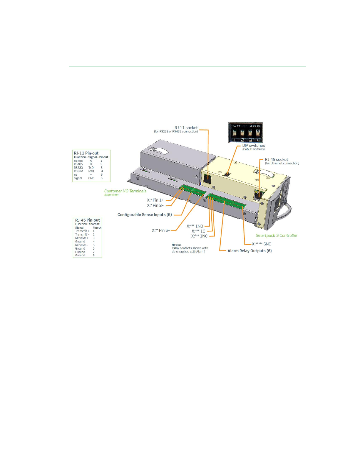
Location of pluggable terminal blocks, RS232/RS485 port and Ethernet connector in
the Smartpack S controller (the pluggable terminals may be black or green)
All the controller’s system connections to the system’s backplane are implemented via an
edge connector, when inserting the controller in the power system.
Notice that when using the RS232 / RS485 port, you must configure RS232 to COM1 and
RS485 to COM2, e.g. via PowerSuite.

Erro! Use a guia Página Inicial para aplicar Heading 1 ao texto que deverá
aparecer aqui. Erro! Use a guia Página Inicial para aplicar Heading 1 ao texto
que deverá aparecer aqui.
User’s Guide FlatpackS Rectifier & Supervision Modules, 11
Connection Drawing
Use this drawing as a customer connection reference for all cabling. You find the exact
location of connection terminals, plugs, DIP switches, jumpers, etc. by referring to chapter
“Location of Connector, Communication Ports” on page 11.
Connection Drawing for Smartpack S controller
The configurable inputs 1 through 4 operate in the range of max. – 10 to +10VDC, and
are intended for great accurate measurements, e.g. for temperature sensing using an
external temperature NTC probe. Also, these inputs are suitable for monitoring other
sensors (of pressure, humidity, etc.) that output 4mA to 20mA. An external 470 ohms
resistor is then to be connected to the input’s terminals on the controller, in parallel with
the sensor’s cables.
The configurable inputs 5 and 6 operate in the range of 0 to 75VDC, and are intended
for e.g. system voltage and battery symmetry measurements.

Erro! Use a guia Página Inicial para aplicar Heading 1 ao texto que deverá
aparecer aqui. Erro! Use a guia Página Inicial para aplicar Heading 1 ao texto
que deverá aparecer aqui.
12 User’s Guide Flatpack2 Rectifier & Supervision Modules,
All the 6 inputs may be configured as Auxiliary Switch (open/close, pull-up or pull-down),
as temperature sense inputs with external NTC sensors, or as Clock inputs.
The SmartpackS controller also have a panel mounted version, that is shown in the picture
below. Both controllers have the same hardware, but in different format.
SmartpackS in the panel version.
Erro! Use a guia Página Inicial para aplicar Heading 1 ao texto que deverá
aparecer aqui. Erro! Use a guia Página Inicial para aplicar Heading 1 ao texto
que deverá aparecer aqui.
User’s Guide FlatpackS Rectifier & Supervision Modules, 13
4. Operation
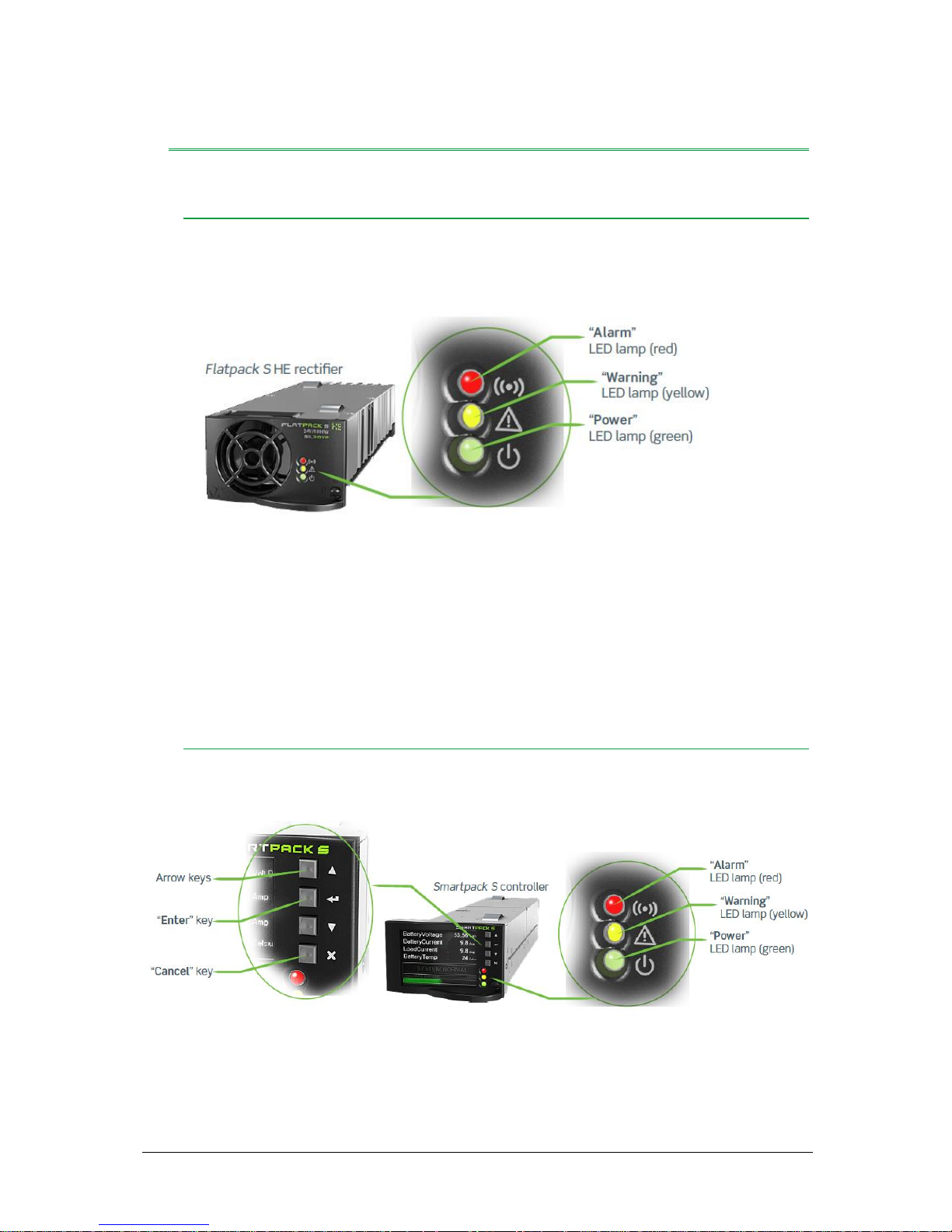
Front Panel — Flatpack S Rectifier Module
The Power LED is OFF (mains unavailable), Flashing (controller accessing information)
or ON (powered).
Flatpack S HE rectifier’s front lamps
The Warning LED is ON (derating or similar minor warning), Flashing (over-voltage
mode) or OFF (OK)
The Alarm LED is ON (shutdown or similar major alarm) or OFF (OK, no alarm)
Front Panel Operation – Smartpack S Controller
This chapter describes the Smartpack S controller’s keys and indicators, and how to
operate the Smartpack S-based DC power system from the controller’s front panel.
Smartpack S controller’s front keys and indicators
Erro! Use a guia Página Inicial para aplicar Heading 1 ao texto que deverá
aparecer aqui. Erro! Use a guia Página Inicial para aplicar Heading 1 ao texto
que deverá aparecer aqui.
14 User’s Guide Flatpack2 Rectifier & Supervision Modules,
Graphical Display
The Graphical Color Display — 2.2” TFT — is either in Status Mode (displays the system’s
status) or in Menu Mode (displays the menu structure).
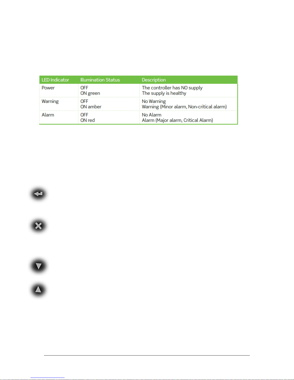
The Smartpack S controller has the following LED indications:
Description of the Smartpack S controller’s LED illumination status
Front Keys
You can operate the power system navigating intuitively through the graphical menu
structure via the following 4 front keys. We recommend using a pen or similar tool to
press the keys, as they are small.
The
Enter
or
Left arrow
key
When entering numbers, a
short press
of this key navigates to the left.
A
long press
of this key to enter and save data
The
Cancel
or
Right arrow
key
When entering numbers, a
short press
of this key navigates to the right.
A
long press
of this key to cancel or abort data
The
Up
and
Down arrow
keys
to navigate up- or downwards the menu icons, point at options and increase
and decrease values

Erro! Use a guia Página Inicial para aplicar Heading 1 ao texto que deverá
aparecer aqui. Erro! Use a guia Página Inicial para aplicar Heading 1 ao texto
que deverá aparecer aqui.
User’s Guide FlatpackS Rectifier & Supervision Modules, 15
Software Menus
The Smartpack S-based system’s functionality is accessed via a network of software
menus and submenus1, enabling you to configure and control the whole power system
from the controller’s front panel. When browsing the menus, the Menu Level Indicator
shows the menu level you are in. Editing parameters is password protected, (default pin
code <0003> should be changed). The display can be in Status Mode or in Menu Mode.
1
From a PC’s web browser, via WebPower, or running the PowerSuite program, you can also access the complete
system functionality, described in the programs’ Online Help

Erro! Use a guia Página Inicial para aplicar Heading 1 ao texto que deverá
aparecer aqui. Erro! Use a guia Página Inicial para aplicar Heading 1 ao texto
que deverá aparecer aqui.
16 User’s Guide Flatpack2 Rectifier & Supervision Modules,
Controller Access — Via Stand-alone PC
You can access the Smartpack S controller directly from a stand-alone computer, or via a
Local Area Network (LAN) if available.
Each controller is shipped with a unique Eltek MAC address stored inside the controller
and marked on the controller’s label, and with the fixed IP address <192.168.10.20>.
Do following to access the controller:
Start the
“Eltek Network Utility”
(ENU) program
(or EVIPSetup.exe)
Connect the computer to the controller
(see
“Accessing the Controller’s
Ethernet Port” on page 5
). Check its MAC address is displayed
Find the computer NIC’s IP address
and subnet mask (network card)
Tip:
using DOS command IPCONFIG, in a Command Prompt window e.g.
computer’s IP address <169.254.52.132> Subnet mask <255.255.0.0>
Change the controller’s IP address
and Network Mask to be in the same range as the
computer’s
Tip:
Using the ENU program,
1. Select the controller,
2. Click in the “Configuration” button
3.
Change e.g. from default <192.168.10.20> <0.0.0.0>
to IP address <169.254.52.133> <255.255.0.0>,
4. Click on the “Enable Static IP” button
Notice: Check that the IP address <169.254.52.133> is
not used, e.g. issuing the DOS command: “Ping
169.254.52.133“
5. Access the controller
’s configuration pages in your Web browser,
e.g. clicking the “Web Interface” button in the ENU program
6. Log in
with the <admin> account
7. Change
the controller’s Device Name
After accessing the controller, you can configure and monitor the power system using a
standard web browser (via WebPower) or via the PowerSuite program. PowerSuite’s
newest version is always available on our FTP server. Contact your closest Eltek
representative.
For detailed functionality description, browse and search through the Functionality
Description Help file (or 350020.073) or WebPower Online Help file.

Erro! Use a guia Página Inicial para aplicar Heading 1 ao texto que deverá
aparecer aqui. Erro! Use a guia Página Inicial para aplicar Heading 1 ao texto
que deverá aparecer aqui.
User’s Guide FlatpackS Rectifier & Supervision Modules, 17
5. Technical Specifications
Model
48/1000 HE
48/1800 HE
Part number
241122.105
241122.125
INPUT DATA
Voltage (nominal)
185 - 270 VAC / 185 - 250 VDC 1)
1952) - 277 VAC / 1952) - 250 VDC 1)
Voltage (operating range)
85 - 300 VAC / 85 - 250 VDC 1)
852) - 305 VAC / 852) - 250 VDC 1)
Current (maximum) @ nominal input, full load
5.9 A
RMS
9.9 A
RMS
Frequency
45 - 66 Hz / 0 Hz1)
Power Factor
> 0.99 at 50% load or more
Protection
Fuse in L & N
Varistor
Shutdown when input voltage is out of operating range
OUTPUT DATA
Voltage (default)
53.5 VDC
Voltage (adjustable range)
43.5 - 57.6 VDC
Power (maximum) @ nominal input
1000 W
1800 W
Power @ 85 VAC
420 W
700 W2)
Current (maximum) @ nominal input
20.9 A (@V
OUT
< 48VDC)
37.5 A (@V
OUT
< 48VDC)
Hold up time, maximum output power
>20ms; output voltage > 41 VDC
>10ms; output voltage > 42 VDC
Current sharing (10 - 100% load)
±5% of maximum current from 10 to 100% load
Static Voltage regulation (10 - 100% load)
±0.5%
Dynamic Voltage regulation
±5.0% for 10-90% or 90-10% load variation, regulation time < 50ms
Ripple
< 150 mV
PP
, 30 MHz bandwidth
Protection
ORing FET
Short circuit proof
High temperature protection
Over voltage Shutdown
OTHER SPECIFICATIONS
Efficiency
Up to 95.5 %
Up to 95.8 %
Isolation
3.0 kVAC - input to output
1.5 kVAC - input to earth
710 VDC - output to earth
Alarms: Red LED
Low and high input voltage shutdown, High and low temperature shutdown, Rectifier
Failure, Overvoltage shutdown on output, Fan failure, Low output voltage alarm, CAN
bus failure
Warnings: Yellow LED
Rectifier in power de-rate mode, Remote output current limit activated, Input voltage
out of range, flashing at overvoltage, Loss of CAN communication with controller
Normal operation: Green LED
MTBF (Telcordia SR-332 Issue I method III (a))
>315 000 (@ T
ambient
: 25 °C)
>300 000 (@ T
ambient
: 25 °C)
Operating temperature (5-95% RH n.cond.
hum.)
Maximum output power de-rates above temp /
to
-40 to + 85°C [-40 to +185°F]
45°C [113°F] / 600W @ 85°C[185°F]
-40 to + 85°C [-40 to +185°F]
45°C [113°F] / 1000W @ 85°C[185°F]
Storage temperature
-40 to +85°C (-40 to +185°F), humidity 0 - 99% RH non-condensing
Dimensions[WxHxD] / Weight
72 x 41.5 x 217mm (2.83 x 1.63 x 8.54”) / < 850 g (1.9 lbs)
DESIGN STANDARDS
Electrical safety
UL 60950-1, EN 60950-1
EMC
ETSI EN 300 386
EN 61000-6-1 / -2 / -3 / -4 TS 61000-6-5
FCC CFR 47 Part 15
Environment
ETSI EN 300 019: 2-1 (Class 1.2), 2-2 (Class 2.3) & 2-3 (Class 3.2)
RoHS (2011/65/EU) and WEEE (2002/96/EC) compliant

Erro! Use a guia Página Inicial para aplicar Heading 1 ao texto que deverá
aparecer aqui. Erro! Use a guia Página Inicial para aplicar Heading 1 ao texto
que deverá aparecer aqui.
18 User’s Guide Flatpack2 Rectifier & Supervision Modules,
1) DC input only allowed when up-stream breaker is rated for the applicable DC input voltage and has a maximum current rating of 32A
2) For HW revisions 1 - 1.31, nominal range is 207 - 277 VAC / 207 - 250 VDC, maximum output power at 176 V
AC/DC
is 1180 W with further linear de-rating to 90W at 122 V
AC/DC
. Not to
be used in applications with 110/120 VAC mains.

www.eltek.com
Headquarters:
Eltek
Gråterudv. 8, Pb 2340 Strømsø, 3003 Drammen, Norway
Phone: +47 32 20 32 00 Fax: +47 32 20 32 10
 Loading...