

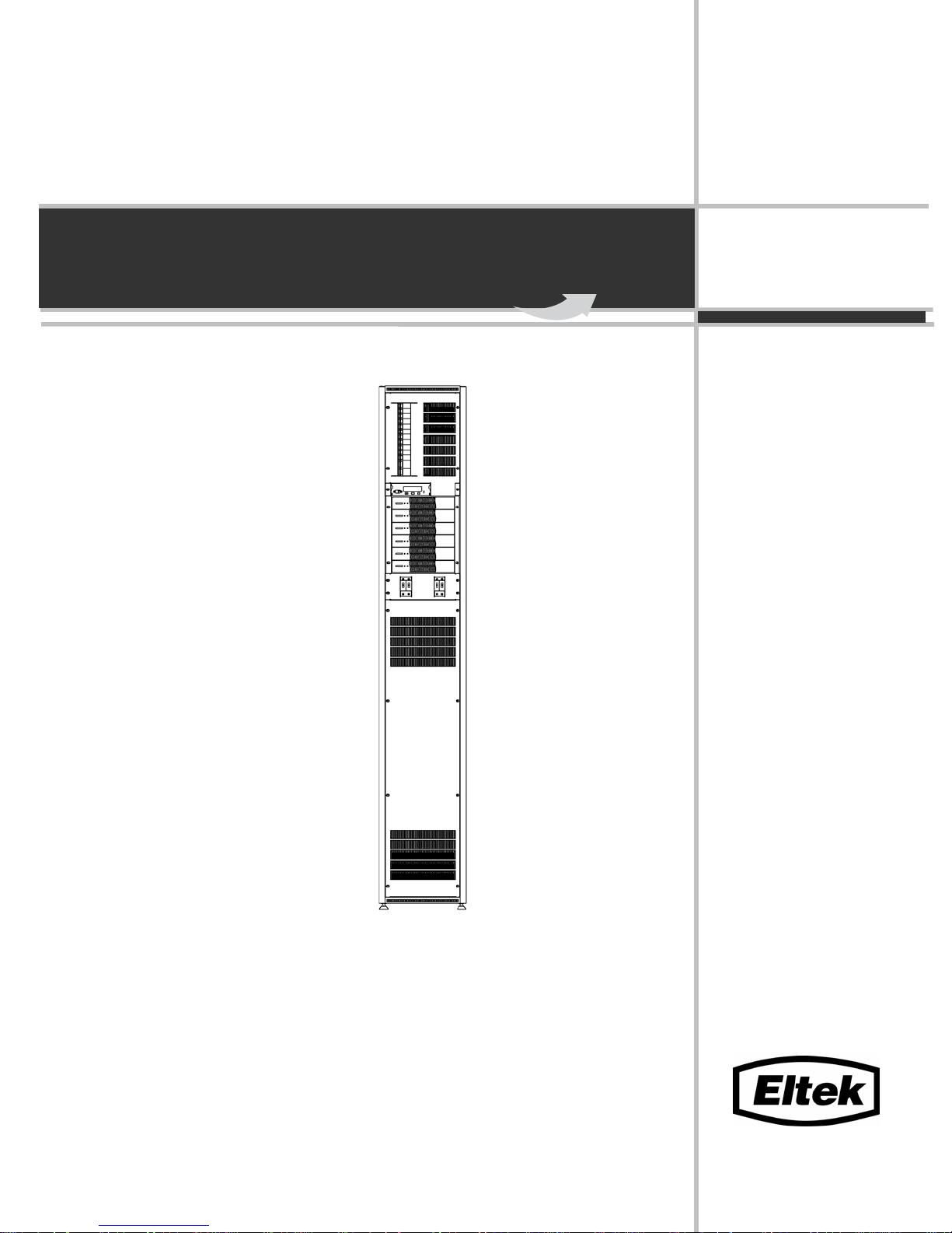
Operation Guide
Power Tower
351401.013
Issue 2
July 2003
Flatpack

Information in this document is subject to change without notice and does not represent a commitment
on the part of ELTEK Energy.
No part of this document may be reproduced or transmitted in any form or by any means — electronic
or mechanical, including photocopying and recording — for any purpose without the explicit written
permission of ELTEK Energy.
Copyright ©: ELTEK Energy, Norway 2006
NS-EN ISO 9001:1994 Certificate no: 900005Q NS-EN ISO 14001:1996 Certificate no: 900005E.
This product holds a CE mark and satisfies all requirements covering relevant standards and directives.
EMC
Generic Immunity Standard
▫ EN61000-6-1 Residential, Commercial and Light Industry
▫ EN61000-6-2 Industrial Environment
Generic Emission Standard
▫ EN61000-6-3 Residential, Commercial and Light Industry
▫ EN61000-6-4 Industrial Environment
ETS 300386 v1.3.1 Telecommunication Equipment
LVD
▫ EN 60950 Safety of Technology Equipment
Certificate no: 900005E
Head Office:
Eltek Energy
P.O. Box 2340 Strømsø
N-3003 DRAMMEN
Norway
Phone: (+47) 32 20 32 00
Fax: (+47) 32 20 32 10
E-Mail:
eltek@eltekenergy.com
Visit our Web site on Internet: http://www.eltekenergy.com
351470.013 Issue 2, July 2003
This document was produced using Microsoft Word
Certificate no: 900005Q
2(48) Operation Guide, Flatpack Power Tower
351401.013v2 July 2003

Table of Contents
1 Table of Contents
1 Table of Contents 3
2 Key Stakeholders/ Document History 5
3 Scope 7
4 Description of Flatpack Power Tower 9
4.1 General ..............................................................................................................9
5 Installation Procedures 11
5.1 Safety Precautions ...........................................................................................11
5.2 Mechanical Installation ................................................................................... 11
5.3 Earth connections ............................................................................................12
5.4 Mains Connections.......................................................................................... 13
5.5 General Arrangement ......................................................................................14
5.6 Installation of rectifiers ................................................................................... 18
6 System Monitoring 27
7 Specification Flatpack Power Tower 29
8 Figures 31
Operation Guide, Flatpack Power Tower
351401.013v2 July 2003
3(48)

Table of Contents
4(48) Operation Guide, Flatpack Power Tower
351401.013v2 July 2003

2 Key Stakeholders/ Document History
2 Key Stakeholders/ Document History
Name Title
Kjartan Albrigtsen Product Manager
Roar Linseth Technical Responsible
Written by Checked by Approved by
Rev Date Sign Date Sign Date Sign
V1 19.02.03 M.G.C. R.L.. K.A.
V2 18.07.03 M.G.C. 04.08.2003 J.K 04.08.2003 I.F
Rev.V1
Rev.V2
The original signatures are recorded on the company’s logistic data system
First issue
Updated to include Imperial measurements
Operation Guide, Flatpack Power Tower
351401.013v2 July 2003
5(48)

2 Key Stakeholders/ Document History
6(48) Operation Guide, Flatpack Power Tower
351401.013v2 July 2003

3 Scope
3 Scope
Flatpack Power Systems are made up of Power Shelves for plug-in rectifier modules, a DC distribution that
includes a monitoring and control unit and optional Batteries.
The power shelves include the necessary amount of rectifiers needed in the system. The DC distribution include
fuses, breakers (MCB`s), load and/or battery disconnect units as well as a Monitoring & Control Unit.
This Operation Guide contains information about the Flatpack Power Tower distribution. It includes information
about alarm connections, DC connections and optional equipment, together with a description on how to install
and commission the distribution.
Operation Guide, Flatpack Power Tower
351401.013v2 July 2003
7(48)

3 Scope
8(48) Operation Guide, Flatpack Power Tower
351401.013v2 July 2003
4 Description of Flatpack Power Tower
4.1 General
4 Description of Flatpack Power Tower
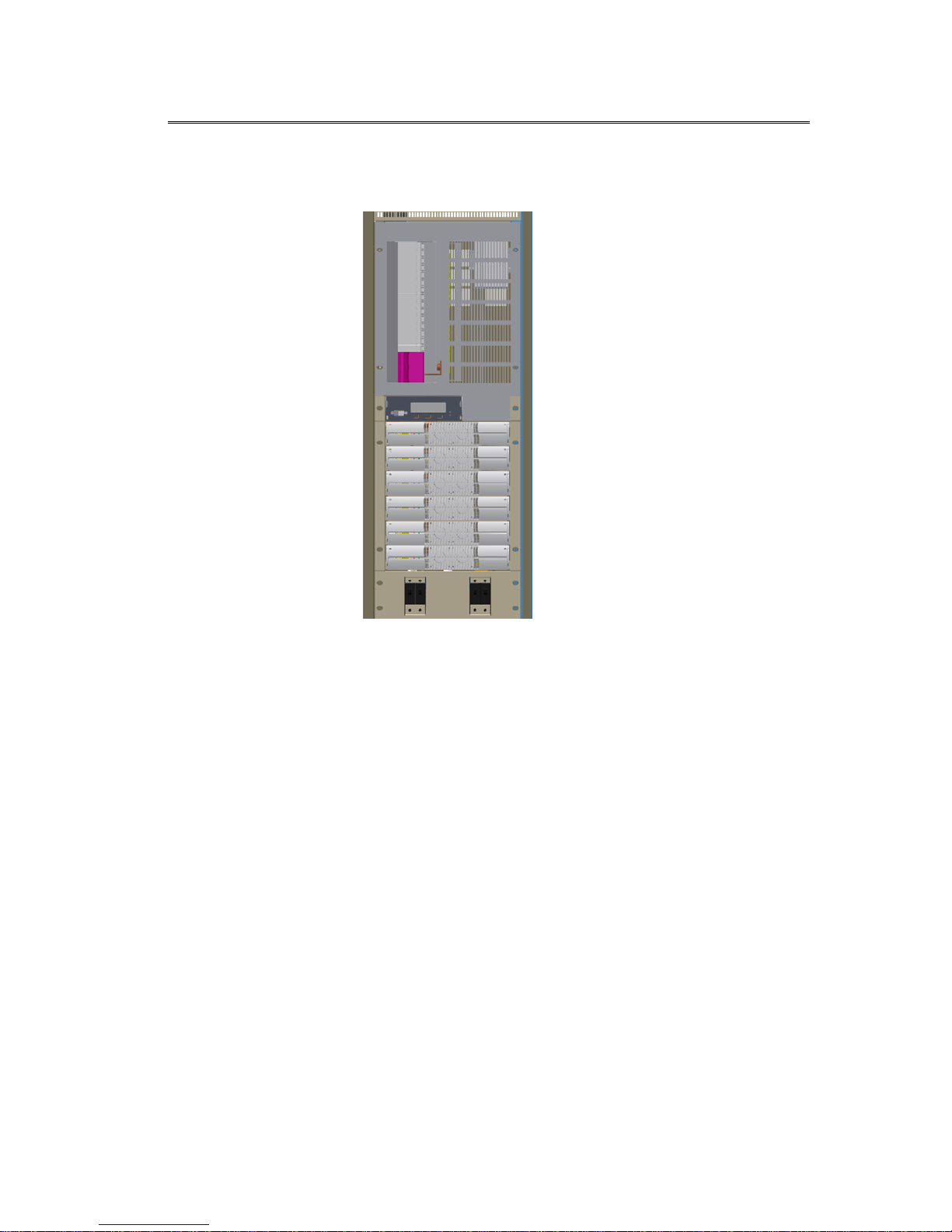
The Power Tower system is a power rack system based on the Flatpack 1500 W 48Vdc.
The systems contain a DC distr., until 6 Flatpack 1500 W 48Vdc. To provided monitoring and control Flatpack
Monitoring/Control Unit (MCU) are used. The distribution is rated for 200A, negative distribution.
The system is designed for cable entry from top. Prepared for 2 battery banks (2 x100Ah) and max. output
current of 200A.
DC output is made by connection between the positive rail and the different load/battery fuses. Negative
distribution is standard.
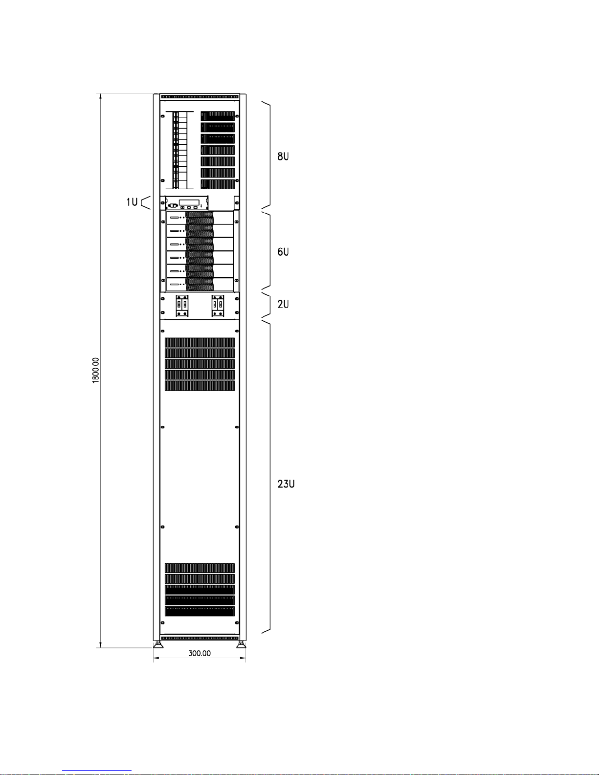
Cabinet size is 300x600x1800mm (11.8”x23.6”x70.9”).
The system is build up from a basic number and prepared for different armament (Valid option
3
).
Operation Guide, Flatpack Power Tower
351401.013v2 July 2003
9(48)
4 Description of Flatpack Power Tower
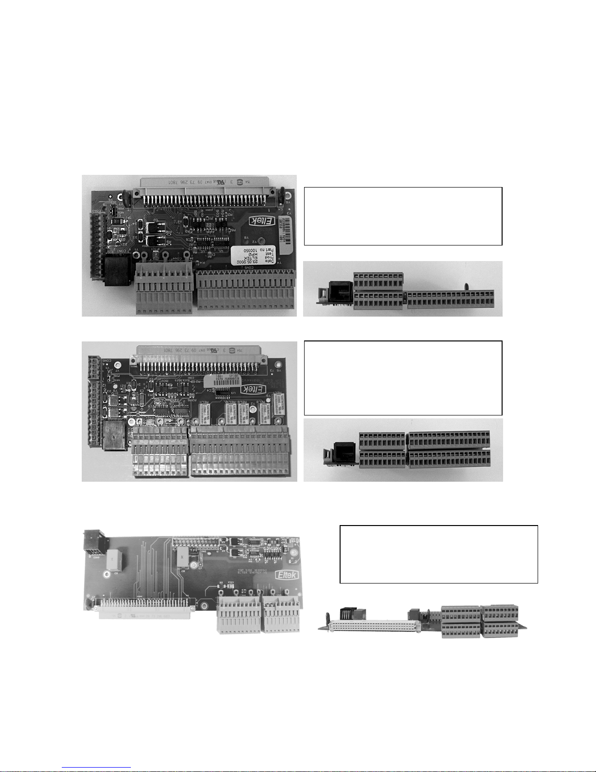
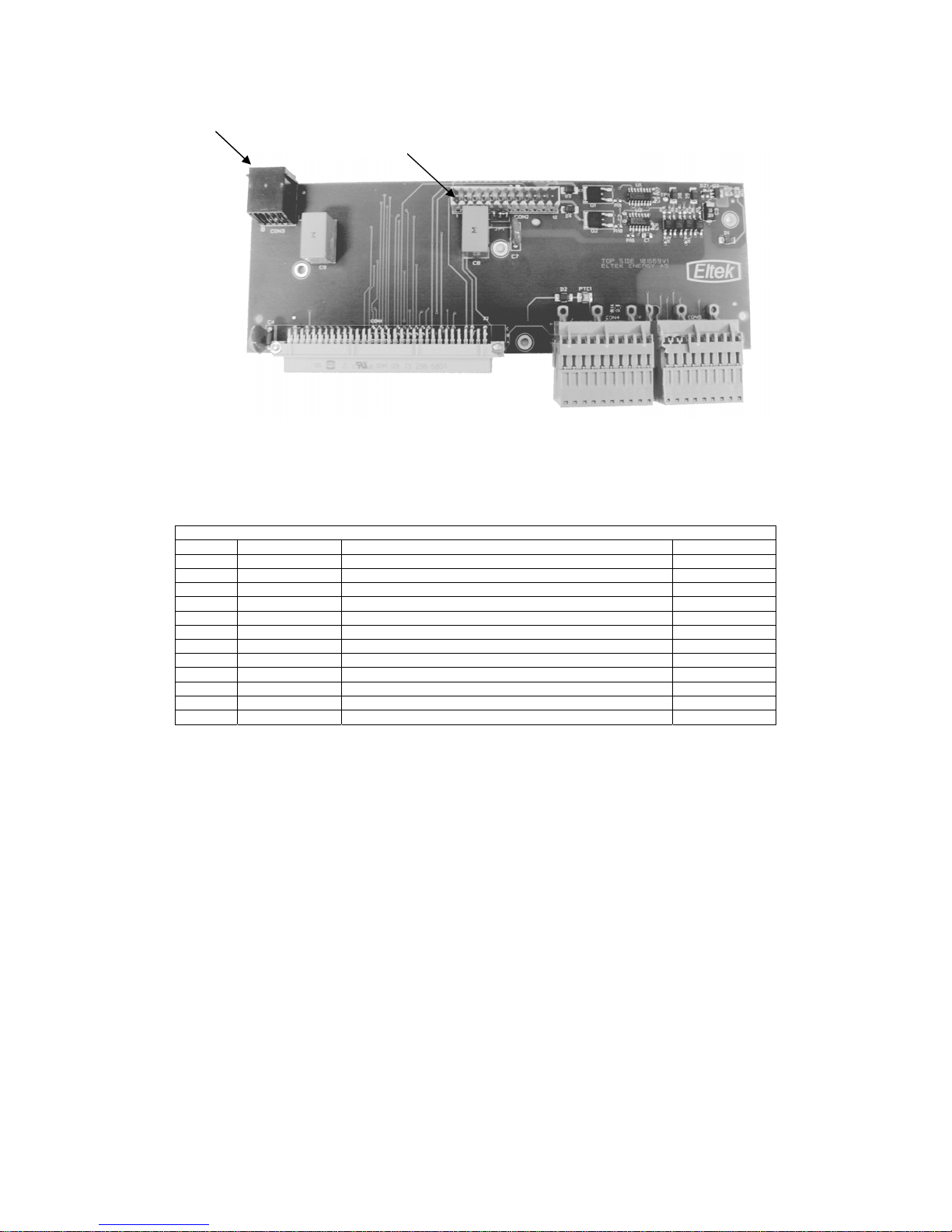
4.1.1 Basic or extended functionality for monitoring and control
The Flatpack Power Tower is available with either basic- or extended functionality for monitoring and control of
the system. The type of interface PCB mounted inside determines whether the distribution unit has basic or
extended functionality. The pictures below show that the interface PCB used distribution units with basic
functionality has less wire connectors than the PCB used in distribution units with extended functionality.
A distribution with extended functionality includes five more alarm relay outputs (totally 11) in addition to the
standard monitoring and control features.
4.1.1.1 Basic functionality
Interface PCB for distribution units with basic
functionality (part no. 100350). Includes all
standard monitoring and control features.
See chapter 5.6.2.2Basic version (PCB part no.
100350) for more details.
4.1.1.2 Extended functionality
4.1.1.3 Front access interface PCB
Interface PCB for distribution units with extended
functionality (part no. 100145). Includes all
standard monitoring and control features and five
additional alarm relay outputs.
See chapter 5.6.2.3 Extended version (PCB part
no 100145)for more details.
Interface PCB for distribution units with basic
functionality (part no. 1001714). Includes all
standard monitoring and control features.
See chapter 5.6.2.4 Front Access PCB (PCB Part
number 101714) for more details.
10(48) Operation Guide, Flatpack Power Tower
351401.013v2 July 2003

5 Installation Procedures
5 Installation Procedures
5.1 Safety Precautions
The equipment described in this manual must only be operated
by Eltek Energy personnel or by persons who have attended a
suitable Eltek Energy training course.
The equipment represents an energy hazard and failure to
observe this could cause terminal injury and invalidate our
warranty.
There are hazardous voltages inside the rectifier system. As
the rectifier units incorporate large charged capacitors, it is
dangerous to work inside the system even if the mains supply
is disconnected.
Products into which our components are incorporated have to
comply with a number of requirements. Installation is to be in
accordance with the recommendations herein.
Please read the manual carefully before using the equipment.
5.2 Mechanical Installation
Installation Step Comments Okay
1 TAKE THE FLATPACK POWER TOWER
OUT OF THE PACKAGING
Procedure 1: Mechanical Installation Flatpack Power Tower
NSPECT THE DISTRIBHUTION UNIT FOR ANY PHYSICAL
I
DAMAGE
. DAMAGED EQUIPMENT SHOULD BE RETURNED TO
YOUR SUPPLIER
Operation Guide, Flatpack Power Tower
351401.013v2 July 2003
11(48)

5 Installa tion Proced ures
5.3 Earth connections
The ground point (M6 stud) is located
behind the AC terminals
The System Ground Cable must be connected to the Common Positive Busbar to ensure that the positive output
of the rectifiers will be connected to ground and the negative output will represent the – 48Vdc supply voltage.
The common positive busbar is connected to the chassis through an earth strap.
Earth connection between
chassis and common
positive bar (system ground)
12(48) Operation Guide, Flatpack Power Tower
351401.013v2 July 2003

5 Installation Procedures
5.4 Mains Connections
Installation Step Comments OK
1. VERIFY WHICH MAINS
CONFIGURATION IS APPLICABLE
FOR YOUR SYSTEM
2. IF NECESSARY, RECONFIGURE THE
MAINS TERMINALS ACCORDING TO
THE SUPPLY AVAILABLE
3. CONNECT THE PROTECTIVE
EARTH BEFORE ANY OF THE LIVE
TERMINATIONS
Procedure 2: Mains Connections Flatpack Power S helf
Refer to label for Power Tower AC connections
Operation Guide, Flatpack Power Tower
351401.013v2 July 2003
13(48)
5 Installa tion Proced ures
5.5 General Arrangement
14(48) Operation Guide, Flatpack Power Tower
351401.013v2 July 2003
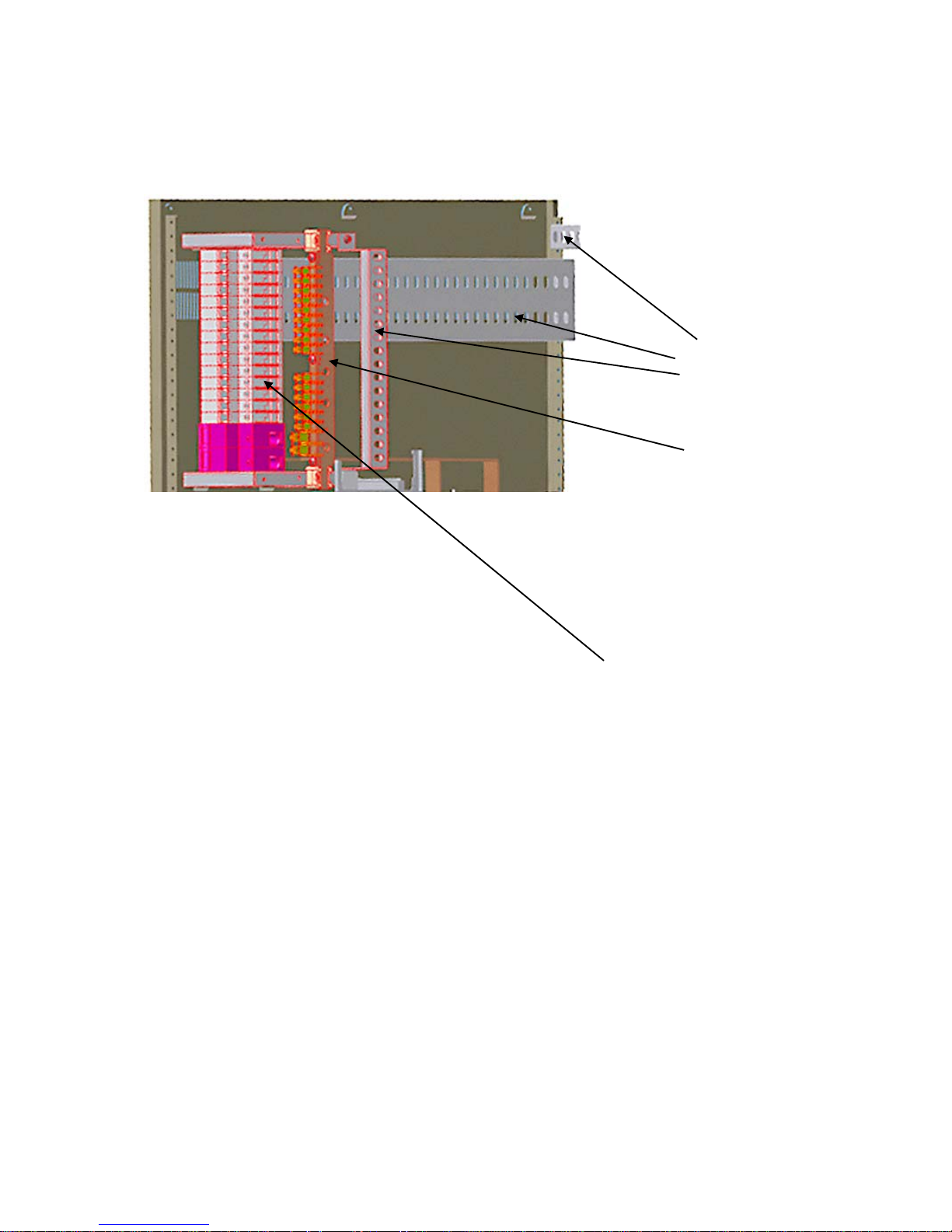
5.5.1 DC Connections/Terminations
5 Installation Procedures
Cord
anchorage
Common
positive busbar
DC load MCB’s with the
negative output on top of
each MCB.
Operation Guide, Flatpack Power Tower
351401.013v2 July 2003
15(48)
5 Installa tion Proced ures
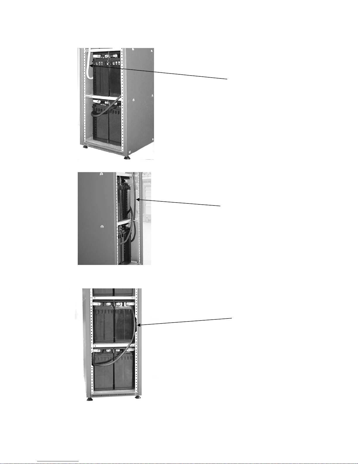
5.5.2 Description of battery connections
Connection of negative
pole from battery fuse
Connection of positive pole
(from common Positive Busbar)
Cutaway view showing
connection of a battery
bank in series
16(48) Operation Guide, Flatpack Power Tower
351401.013v2 July 2003
Batt. Bank No. 1
(Batt.fuse 1)
5 Installation Procedures
Batt. Bank No. 2
(Batt.fuse 2)
5.5.3 Procedure for connection of DC cables
Installation Step Comments OK
1 DECIDE CABLE ENTRY
2 DRESS THE CABLES INTO THE
CABINET
, CUT TO LENGTH AND FIT
CABLE LUGS OR FERRULES IF
APPLICABLE
3 FASTEN THE CABLES TO THE DC
TERMINALS
6 FASTEN ALL CABLES AWAY FROM
SHARP EDGES AND RELIEVE ANY
STRAIN FROM THE TERMINALS
.
The cables or copper bars can enter from top
Use cable cutter and cable lug crimper fitted with
appropriate sized die.
For cables/wires
The holes are dimensioned for M8 bolts, which are fitted
at delivery
See chapter “connections/terminal” for connection
details
Ensure that the cables do not impose any stress to the
terminal connections.
Ensure that the cables do not rest against any sharp edges
inside the cabinet
Operation Guide, Flatpack Power Tower
351401.013v2 July 2003
17(48)

5 Installa tion Proced ures
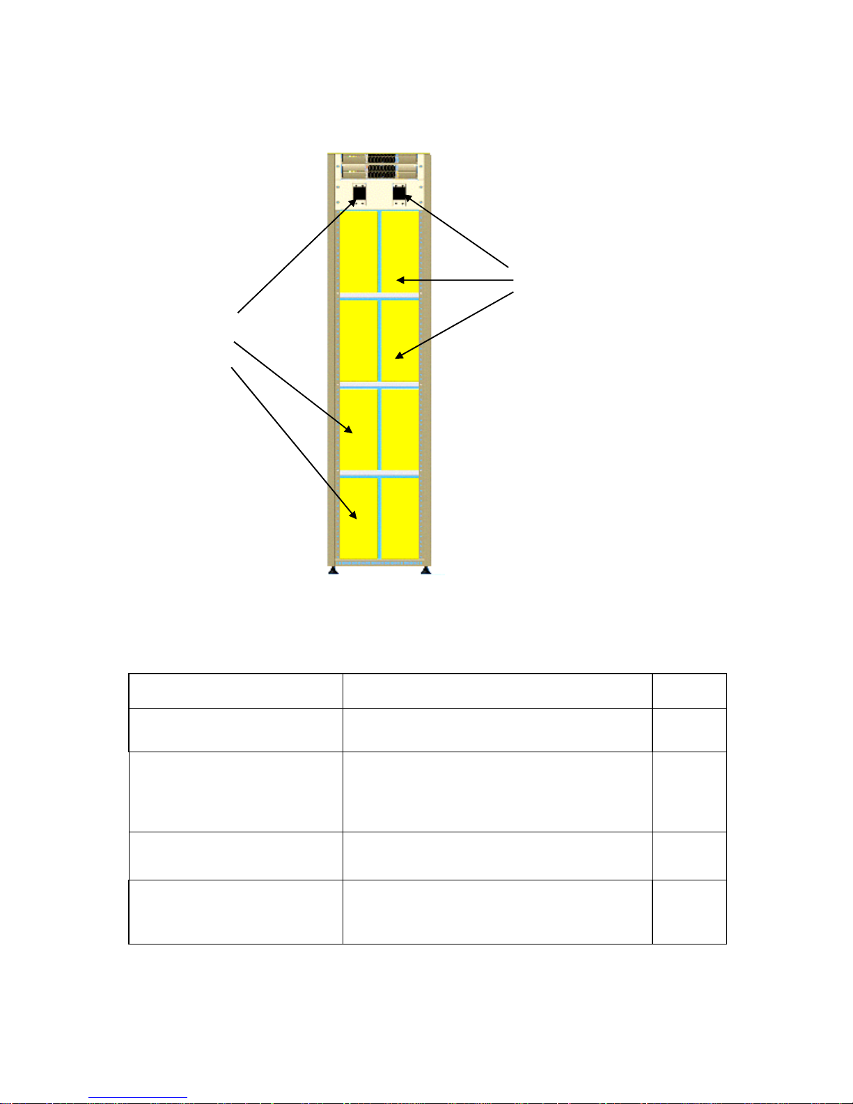
5.6 Installation of rectifiers
Installation of Flatpack 1500 Rectifiers
Installation Step Comments OK
1. PLUG IN THE NEW SMPS
MODULE(S)
2. FASTEN THE MODULE BY PUSHING
THE LEVERS BACK INTO POSITION
3. VERIFY THAT THE RECTIFIER IS ON
4. MOUNT BLIND PANELS ON EMPTY
RECTIFIER POSITIONS
Make sure that the levers on each side of the rectifier are
pulled forward (see section 5.6.1)
The green “Power” LED is lit and no alarm is activated
For safety reasons all vacant rectifier positions must be
covered by blind panels
Procedure 3: Installation of Rectifiers
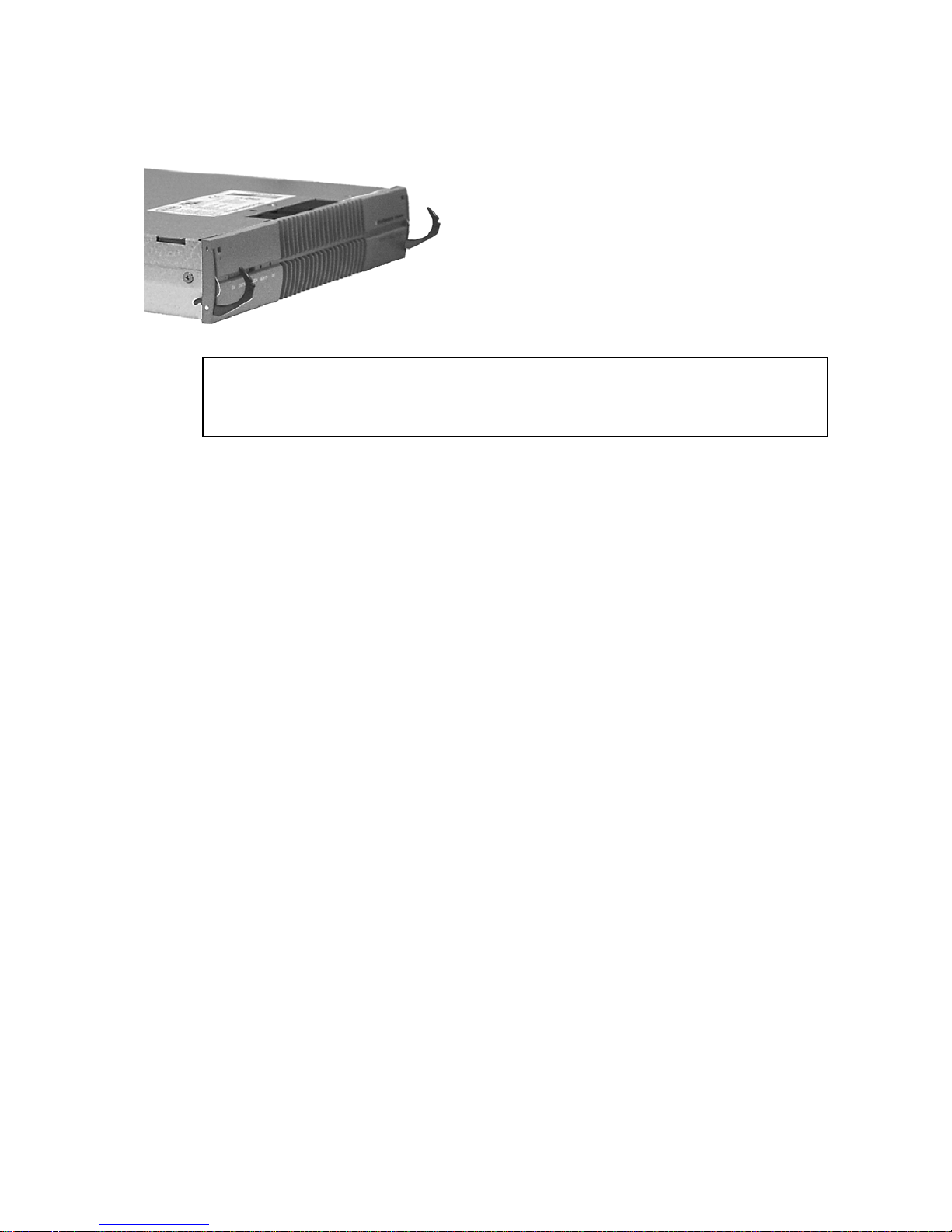
5.6.1 Handles and locking me chanism
The Flatpack 1500 rectifier incorporates handles that serve two purposes:
1.TO LOCK THE RECTIFIER INTO POSITION
When the rectifier is plugged into its slot, it is then locked into position using the handles on either side of the
front panel. The handles must be rotated into their housings and firmly pushed home only after the rectifier is in
position, failure to do so will prevent the rectifier from making proper contact.
18(48) Operation Guide, Flatpack Power Tower
Handle in locked position
351401.013v2 July 2003
5 Installation Procedures
To unlock and release the handles, insert a small screw driver into the holes in the upper corners of the rectifier
front panel to release the spring mechanism. Do not use excessive force. The handle will release and pop out.
2. PULL-OUT HANDLES
When both handles are released use them to pull the rectifier loose.
o Do not hold or hand-carry the rectifier by its handles.
o Use gentle force, when releasing the handles from their locked position
Operation Guide, Flatpack Power Tower
351401.013v2 July 2003
19(48)
5 Installa tion Proced ures
5.6.2 Description of alarm and sign al connections
Three types of PCB`s are used for this purpose (Basic and Extended version). All PCB`s are described in this
chapter. Please verify which type of PCB is mounted in your system before any connections are made (see
chapter “Basic or extended functionality for monitoring and control” for details).
5.6.2.1 Alarm relay specification
Nominal switching capacity 2A/30V DC
Maximum switching power 60W (resistive load)
Maximum switching voltage 220V DC
Maximum switching current 2A DC
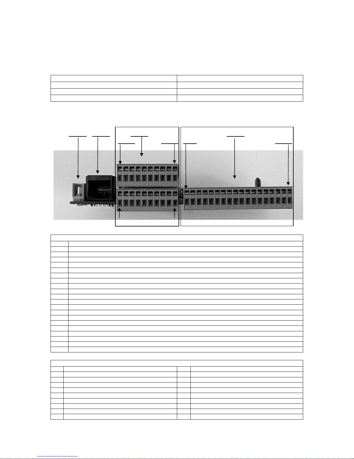
5.6.2.2 Basic version (PCB part no. 100350)
CON2 CON3 CON4 CON5
PIN11
PIN20 PIN1 PIN18
PIN1 PIN10
PIN DESCRIPTION
1 Digital Input 1 (When shorted to AGND (PIN2), the input will be de-activated)
2 AGND
3 Digital Input 2 (When shorted to AGND (PIN4), the input will be de-activated)
4 AGND
5 Digital Input 3 (When shorted to AGND (PIN6), the input will be de-activated)
6 AGND
7 Digital Input 4 (When shorted to AGND (PIN8), the input will be de-activated)
8 AGND
9 Symmetry Alarm 2 (Digital input referred to AGND (PIN9). For use together with external symmetry alarm PCB(`s).
10 AGND
11 Symmetry Alarm 1 (+) (Analog measurement between PIN11 and PIN12)
12 Symmetry Alarm 1 (-) (Analog measurement between PIN11 and PIN12)
13 Symmetry Alarm 3 (+) (Analog measurement between PIN13 and PIN14)
14 Symmetry Alarm 3 (-) (Analog measurement between PIN13 and PIN14)
15 AUX.power output (+) (20Vdc/ 200mA (21V ±5%) Intended for powering a modem)
16 AUX.power output (-) (20Vdc/ 200mA (21V ±5%) Intended for powering a modem)
17 Not in use
18 Temperature sensor (+) (For connection of temperature probe)
19 Temperature sensor (-) (For connection of temperature probe)
20 Temperature sensor (cable screen)
CON4 PIN ASSIGNMENT (for basic PCB version part no. 100350)
PIN DESCRIPTION PIN DESCRIPTION
1 Alarm relay 6 NC (Alarm relay output) 10 Alarm relay 3 NC (Alarm relay output)
2 Alarm relay 6 NO (Alarm relay output) 11 Alarm relay 3 NO (Alarm relay output)
3 Alarm relay 6 C (Alarm relay output) 12 Alarm relay 3 C (Alarm relay output)
4 Alarm relay 5 NC (Alarm relay output) 13 Alarm relay 2 NC (Alarm relay output)
5 Alarm relay 5 NO (Alarm relay output) 14 Alarm relay 2 NO (Alarm relay output)
6 Alarm relay 5 C (Alarm relay output) 15 Alarm relay 2 C (Alarm relay output)
7 Alarm relay 4 NC (Alarm relay output) 16 Alarm relay 1 NC (Alarm relay output)
8 Alarm relay 4 NO (Alarm relay output) 17 Alarm relay 1 NO (Alarm relay output)
9 Alarm relay 4 C (Alarm relay output) 18 Alarm relay 1 C (Alarm relay output)
CON5 PIN ASSIGNMENT (for basic PCB version part no. 100350)
20(48) Operation Guide, Flatpack Power Tower
351401.013v2 July 2003

5 Installation Procedures
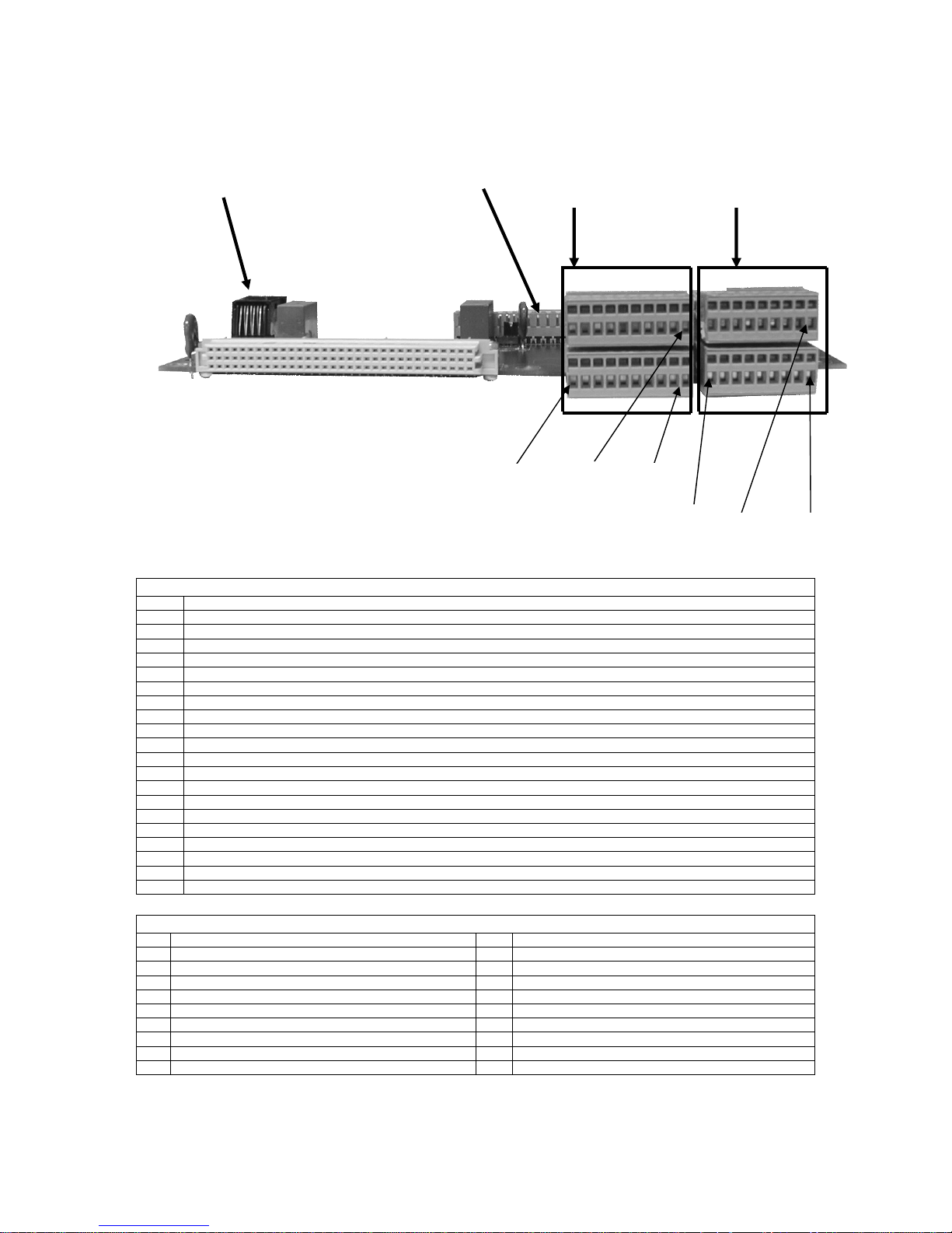
5.6.2.3 Extended version (PCB part no 100145)
CON2 CON3 CON4 CON5
PIN11
PIN20 PIN19 PIN36
PIN1 PIN10 PIN1 PIN18
PIN DESCRIPTION
1 Digital Input 1 (When shorted to AGND (PIN2), the input will be de-activated)
2 AGND
3 Digital Input 2 (When shorted to AGND (PIN4), the input will be de-activated)
4 AGND
5 Digital Input 3 (When shorted to AGND (PIN6), the input will be de-activated)
6 AGND
7 Digital Input 4 (When shorted to AGND (PIN8), the input will be de-activated)
8 AGND
9 Symmetry Alarm 2 (Digital input referred to AGND (PIN9). For use together with external symmetry alarm PCB(`s).
10 AGND
11 LVD1 status (For external verification of contactor state. An alarm switch mounted on the contactor must be hardwired to CON6)
12 LVD1 status (For external verification of contactor state. An alarm switch mounted on the contactor must be hardwired to CON6)
13 LVD2 status (For external verification of contactor state. An alarm switch mounted on the contactor must be hardwired to CON6)
14 LVD2 status (For external verification of contactor state. An alarm switch mounted on the contactor must be hardwired to CON6)
15 Symmetry Alarm 1 (+) (Analog measurement between PIN11 and PIN12)
16 Symmetry Alarm 1 (-) (Analog measurement between PIN11 and PIN12)
17 Symmetry Alarm 3 (+) (Analog measurement between PIN13 and PIN14). Not in use
18 Symmetry Alarm 3 (-) (Analog measurement between PIN13 and PIN14). Not in use
19 AUX.power output (+) (20Vdc/ 200mA (21V ±5%) Intended for powering a modem)
20 AUX.power output (-) (20Vdc/ 200mA (21V ±5%) Intended for powering a modem)
CON4 PIN ASSIGNMENT (for extended PCB version part no. 100145)
PIN DESCRIPTION PIN DESCRIPTION
1 Temperature sensor (+) (For connection of temp. probe) 19 Alarm relay 6 NC (Alarm relay output)
2 Temperature sensor (-) (For connection of temp. probe) 20 Alarm relay 6 NO (Alarm relay output)
3 Temperature sensor (cable screen) 21 Alarm relay 6 C (Alarm relay output)
4 Alarm relay 11 NC (Alarm relay output) 22 Alarm relay 5 NC (Alarm relay output)
5 Alarm relay 11 NO (Alarm relay output) 23 Alarm relay 5 NO (Alarm relay output)
6 Alarm relay 11 C (Alarm relay output) 24 Alarm relay 5 C (Alarm relay output)
7 Alarm relay 10 NC (Alarm relay output) 25 Alarm relay 4 NC (Alarm relay output)
8 Alarm relay 10 NO (Alarm relay output) 26 Alarm relay 4 NO (Alarm relay output)
9 Alarm relay 10 C (Alarm relay output) 27 Alarm relay 4 C (Alarm relay output)
10 Alarm relay 9 NC (Alarm relay output) 28 Alarm relay 3 NC (Alarm relay output)
11 Alarm relay 9 NO (Alarm relay output) 29 Alarm relay 3 NO (Alarm relay output)
12 Alarm relay 9 C (Alarm relay output) 30 Alarm relay 3 C (Alarm relay output)
13 Alarm relay 8 NC (Alarm relay output) 31 Alarm relay 2 NC (Alarm relay output)
14 Alarm relay 8 NO (Alarm relay output) 32 Alarm relay 2 NO (Alarm relay output)
15 Alarm relay 8 C (Alarm relay output) 33 Alarm relay 2 C (Alarm relay output)
16 Alarm relay 7 NC (Alarm relay output) 34 Alarm relay 1 NC (Alarm relay output)
17 Alarm relay 7 NO (Alarm relay output) 35 Alarm relay 1 NO (Alarm relay output)
18 Alarm relay 7 C (Alarm relay output) 36 Alarm relay 1 C (Alarm relay output)
CON5 PIN ASSIGNMENT (for extended PCB version part no. 100145)
Operation Guide, Flatpack Power Tower
351401.013v2 July 2003
21(48)
5 Installa tion Proced ures
CON 3
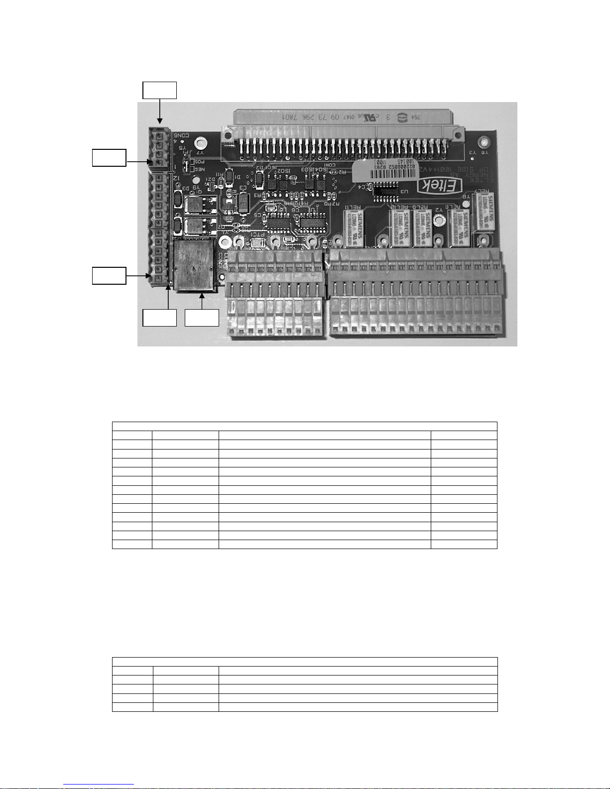
5.6.2.4 Front Access PCB (PCB Part number 101714)
CON 2
CON 4 CON 5
Pin 1
Pin 20
Pin 10
Pin 1
CON4 PIN ASSIGNMENT (for basic PCB version part no. 101714)
PIN DESCRIPTION
1 Digital Input 1 (When shorted to AGND (PIN2), the input will be de-activated)
2 AGND
3 Digital Input 2 (When shorted to AGND (PIN4), the input will be de-activated)
4 AGND
5 Digital Input 3 (When shorted to AGND (PIN6), the input will be de-activated)
6 AGND
7 Digital Input 4 (When shorted to AGND (PIN8), the input will be de-activated)
8 AGND
9 Symmetry Alarm 2 (Digital input referred to AGND (PIN9). For use together with external symmetry alarm PCB(`s).
10 AGND
11 Symmetry Alarm 1 (+) (Analog measurement between PIN11 and PIN12)
12 Symmetry Alarm 1 (-) (Analog measurement between PIN11 and PIN12)
13 Symmetry Alarm 3 (+) (Analog measurement between PIN13 and PIN14)
14 Symmetry Alarm 3 (-) (Analog measurement between PIN13 and PIN14)
15 AUX.power output (+) (20Vdc/ 200mA (21V ±5%) Intended for powering a modem)
16 AUX.power output (-) (20Vdc/ 200mA (21V ±5%) Intended for powering a modem)
17 Not in use
18 Temperature sensor (+) (For connection of temperature probe)
19 Temperature sensor (-) (For connection of temperature probe)
20 Temperature sensor (cable screen)
PIN DESCRIPTION PIN DESCRIPTION
1 Alarm relay 6 NC (Alarm relay output) 10 Alarm relay 3 NC (Alarm relay output)
2 Alarm relay 6 NO (Alarm relay output) 11 Alarm relay 3 NO (Alarm relay output)
3 Alarm relay 6 C (Alarm relay output) 12 Alarm relay 3 C (Alarm relay output)
4 Alarm relay 5 NC (Alarm relay output) 13 Alarm relay 2 NC (Alarm relay output)
5 Alarm relay 5 NO (Alarm relay output) 14 Alarm relay 2 NO (Alarm relay output)
6 Alarm relay 5 C (Alarm relay output) 15 Alarm relay 2 C (Alarm relay output)
7 Alarm relay 4 NC (Alarm relay output) 16 Alarm relay 1 NC (Alarm relay output)
8 Alarm relay 4 NO (Alarm relay output) 17 Alarm relay 1 NO (Alarm relay output)
9 Alarm relay 4 C (Alarm relay output) 18 Alarm relay 1 C (Alarm relay output)
CON5 PIN ASSIGNMENT (for basic PCB version part no. 101714)
Pin 18
Pin 9
22(48) Operation Guide, Flatpack Power Tower
351401.013v2 July 2003
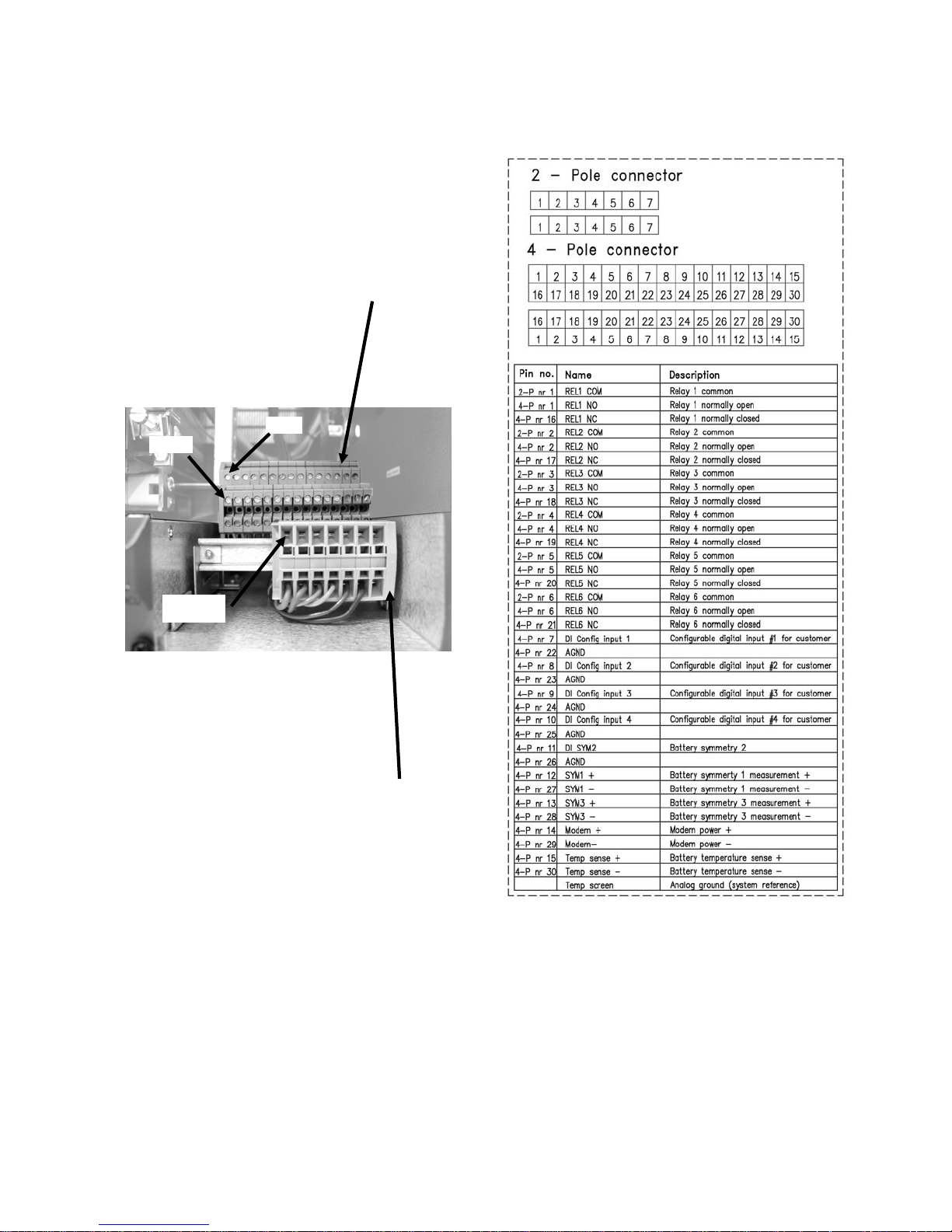
5.6.2.5 Front access from PCB 100350
Pin 16
Pin 1
4 - pole connector
Pin 1
2 – pole connector
5 Installation Procedures
Operation Guide, Flatpack Power Tower
351401.013v2 July 2003
23(48)
5 Installa tion Proced ures
5.6.2.6 Connectors for Internal system wiring
PIN1
PIN1
CON6
CON3 CON2
The connectors CON2 and CON3 have the same pin assignment on both the basic and the extended PCB
versions. CON6 is only mounted on the extended version PCB. CON3 is used for rectifier and power shelf
communication. All three connectors are only used for internal system wiring, which has been done at the
factory. These connectors are not involved in the system installation and commissioning process. The tables
below show the pin assignment for CON2 and CON6.
Pin no. Name Description Classification
Batt curr + Current measurement, battery A/I
1
Batt curr - Current measurement, battery A/I
2
Rect curr + Current measurement, rectifier A/I
3
Rect curr - Current measurement, rectifier A/I
4
Power + Power for Flatpack Monitoring/Control Unit O
5
Power - Power for Flatpack Monitoring/Control Unit O
6
Vdc+ Voltage measurement, dc bus voltage A/I
7
Signal ref/Vdc- Voltage measurement, dc bus voltage A/I
8
DI Batt fuse Battery fuse state D/I
9
Load fuse Load fuse detection D/I
10
LVD1 Contactor control O
11
LVD2 Contactor control O
12
CON2 PIN ASSIGNMENT
CON6 can be used to get an alarm via voltage free change over contacts, if the battery/load disconnect
contactor(s) fail to change state, or remains mechanically locked in any state. The contactors must be equipped
with alarm switch(s). CON6 is only used to improve the connectivity to external equipment. The alarm signal(s)
from the alarm switch(s) are connected to CON6 so they can be obtained on CON4 for easy connection to
external monitoring equipment.
The same alarm(s) can be transmitted to a remote/local management station via software in Flatpack MCU, if the
signal(s) are connected directly to any of the programmable digital input(s) on CON4. See “Flatpack MCU
Operation Guide” for detailed information about digital inputs and how they are programmed in software.
Pin no. Name Description
LVD1 status For internal wiring to alarm switch on LVD1. Obtained on CON4 for external connection
1
LVD1 status For internal wiring to alarm switch on LVD1. Obtained on CON4 for external connection
2
LVD2 status For internal wiring to alarm switch on LVD2. Obtained on CON4 for external connection
3
LVD2 status For internal wiring to alarm switch on LVD2. Obtained on CON4 for external connection
4
CON6 PIN ASSIGNMENT
24(48) Operation Guide, Flatpack Power Tower
351401.013v2 July 2003
5 Installation Procedures
5.6.2.7 Internal connections for front access Interface PCB
Con 3
The connectors CON2 and CON3 have the same pin assignment on both the basic and the extended PCB
versions. CON3 is used for rectifier and power shelf communication. All three connectors are only used for
internal system wiring, which has been done at the factory. These connectors are not involved in the system
installation and commissioning process. The table below shows the pin assignment for CON2.
Pin no. Name Description Classification
Batt curr + Current measurement, battery A/I
1
Batt curr - Current measurement, battery A/I
2
Rect curr + Current measurement, rectifier A/I
3
Rect curr - Current measurement, rectifier A/I
4
Power + Power for Flatpack Monitoring/Control Unit O
5
Power - Power for Flatpack Monitoring/Control Unit O
6
Vdc+ Voltage measurement, dc bus voltage A/I
7
Signal ref/Vdc- Voltage measurement, dc bus voltage A/I
8
DI Batt fuse Battery fuse state D/I
9
Load fuse Load fuse detection D/I
10
LVD1 Contactor control O
11
LVD2 Contactor control O
12
Con 2 Pin 1
CON2 PIN ASSIGNMENT
Operation Guide, Flatpack Power Tower
351401.013v2 July 2003
25(48)

5 Installa tion Proced ures
26(48) Operation Guide, Flatpack Power Tower
351401.013v2 July 2003

6 System Monitoring
6 System Monitoring
The Flatpack system can be monitored locally or from a remote location via the Flatpack MCU Monitoring &
Control Unit. The Flatpack MCU monitors and controls the entire rectifier system including distribution and
batteries, as well as other equipment on site.
Please refer to the Flatpack MCU Operation Guide, for detailed information about system monitoring
Operation Guide, Flatpack Power Tower
351401.013v2 July 2003
27(48)

6 System Moni toring
28(48) Operation Guide, Flatpack Power Tower
351401.013v2 July 2003

7 Specification Flatpack Power Tower
.
7 Specification Flatpack Power Tower
FlatPack Power Tower
SPECIFICATION
RATING
Voltage 0-60Vdc
Max. Current 200A
DISTRIBUTION OPTIONS
No. of Load breakers
(Note: Customer
distribution can be
made on request)
No. of Battery fuses 2 (max. 200A)
Low Voltage Battery
Disconnect
Low Voltage Load
Disconnect
MONITORING
Monitoring Unit1 Flatpack MCU
RS 232 serial port 1
Local operation Menu driven software via
Remote operation Winpower via modems
Alarm relays 6 relays are standard
Visual indications Green LED – Power ON
Digital inputs 4 (can be used to monitor
Current
measurements
Load fuse alarm Yes
Battery fuse alarm Yes
Low voltage battery
disconnect alarm
Low voltage load
disconnect alarm
Low output voltage
alarms
High output voltage
alarms
See Flatpack MCU datasheet for d et a i l ed i n f ormation regarding monitoring & control
2 x 125A Siemens
+11 x (Siemens 5SY4)
breakers
or
15 x (Cbi, Q-series)
breakers
1 (option)
1 (option)
Keypads and LCD
NMS via SNMP-agent
5 extra relays are optional
Red LED – Active alarm(s)
LCD – system status and
interrogation via keypads
external equipment)
- Battery current
- Rectifier current
- Load current
(calculated)
Yes
Yes
2 (individual alarm levels)
2 (individual alarm levels)
CONNECTIONS
Battery
connections
Load MCB
connections
Alarm
connections
OTHER SPECIFICATIONS
Complies to the
following
standards
Isolation 3.0 KVAC – input and output
Operating Temp -10 to +70°C / 14 to +158°F
Storage Temp -40 to +85°C / -40 to +185°F
Humidity Operating:
Dimensions W:300mm D:600mm H:1800mm
Weight Max. 65kg (143lbs) excl. MCU
Battery cable, M6
Negative, directly in the breakers
Positive, common positive buss
bars
Plug-in wire connectors located in
the rear of the MCU (front access
optional)
Electrical safety:
EN 60950
EMC:
EN 300 386 V.1.3.1 (Class B)
EN 61000-6-3
(emission, light industry)
EN 61000-6-2
(immunity, industry)
Environment:
ETS 300 019
1.5 KVAC – input earth
1.0 KVDC – output earth
5% to 95% RH non-condensing
Storage:
0% to 99% RH non-condensing
W:11.81” D:23.62” H:70.87”
Operation Guide, Flatpack Power Tower
351401.013v2 July 2003
29(48)

7 Specification Flatpack Power Tower
30(48) Operation Guide, Flatpack Power Tower
351401.013v2 July 2003

8 Figures
8 Figures
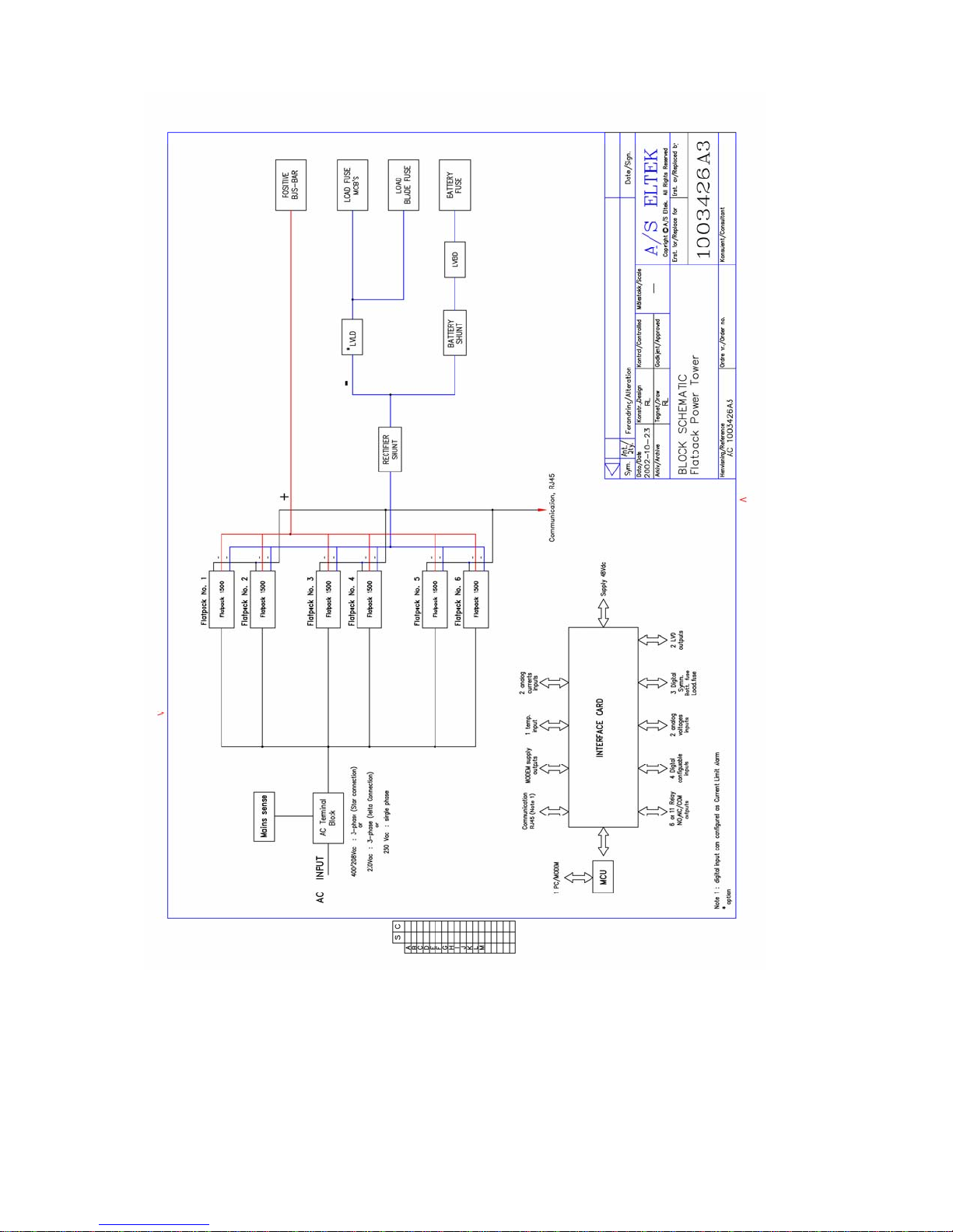
Figure 1 Block Schematic, Flatpack Power Tower ................................................................................................. 32
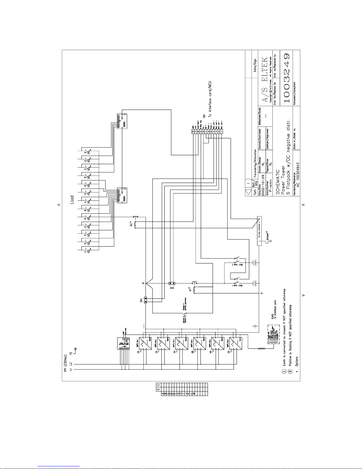
Figure 2 Schematic, 1Ph (230Vac) .......................................................................................................................... 34
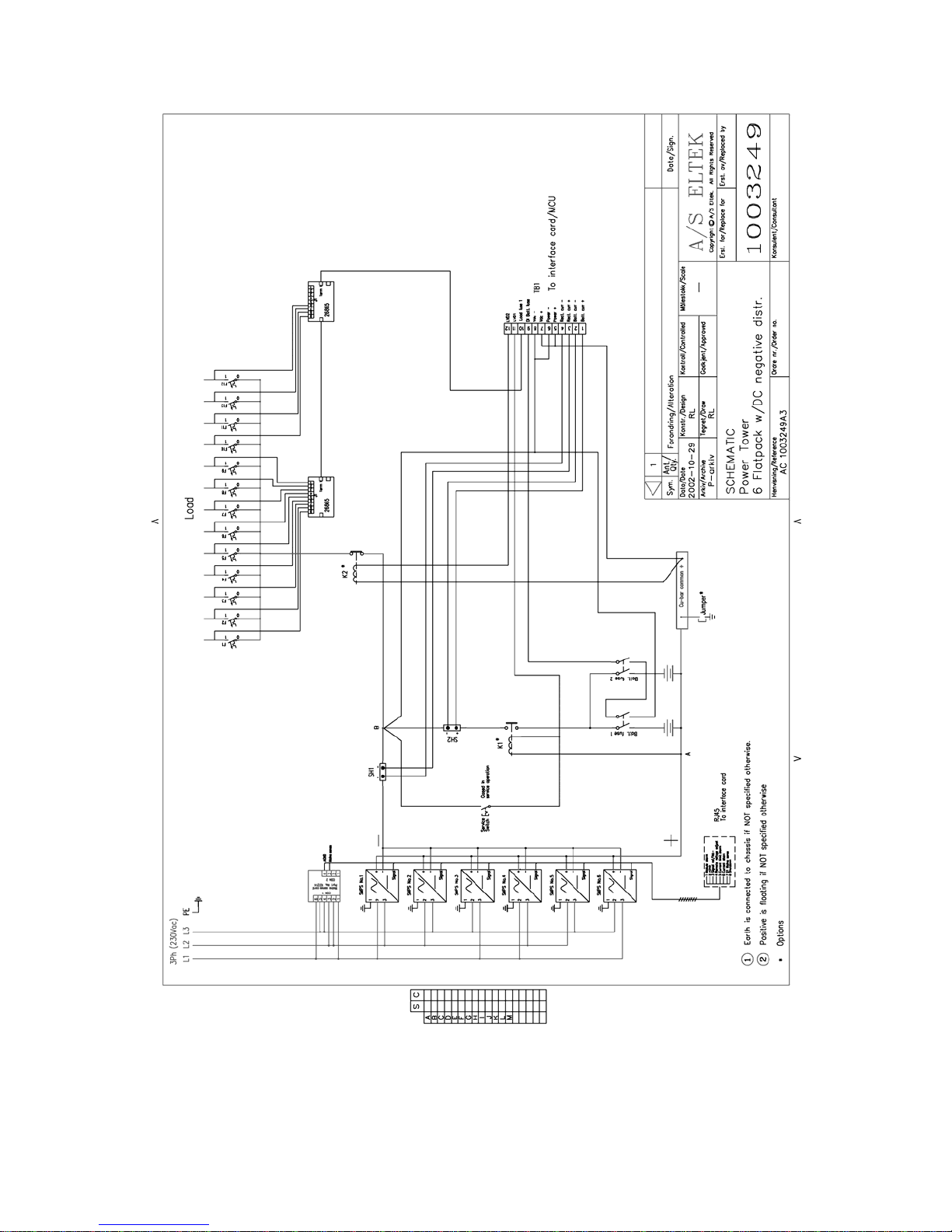
Figure 3 Schematic, 3Ph (230Vac) ......................................................................................................................... 36
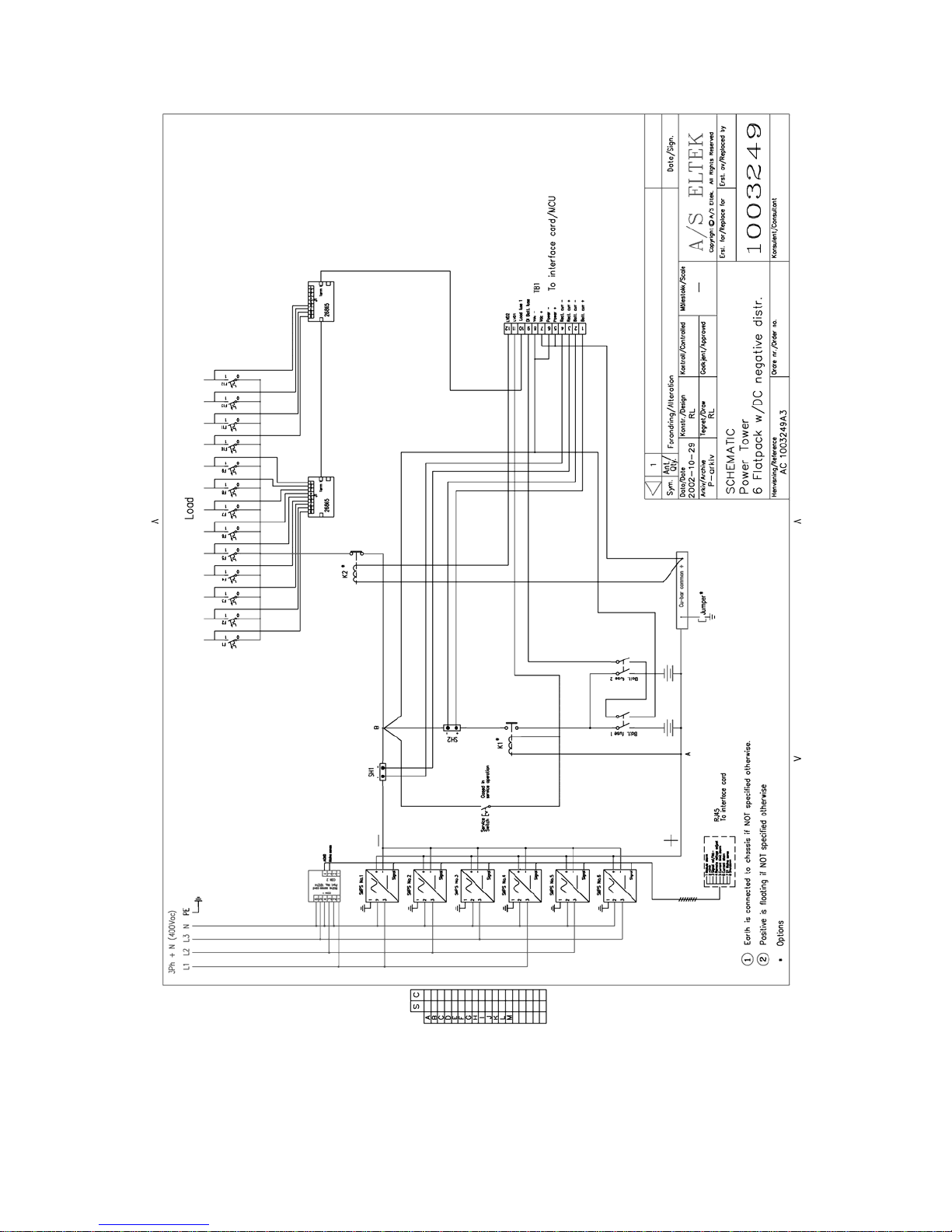
Figure 4 Schematic Power Tower, 3Ph +N (400Vac)............................................................................................. 38
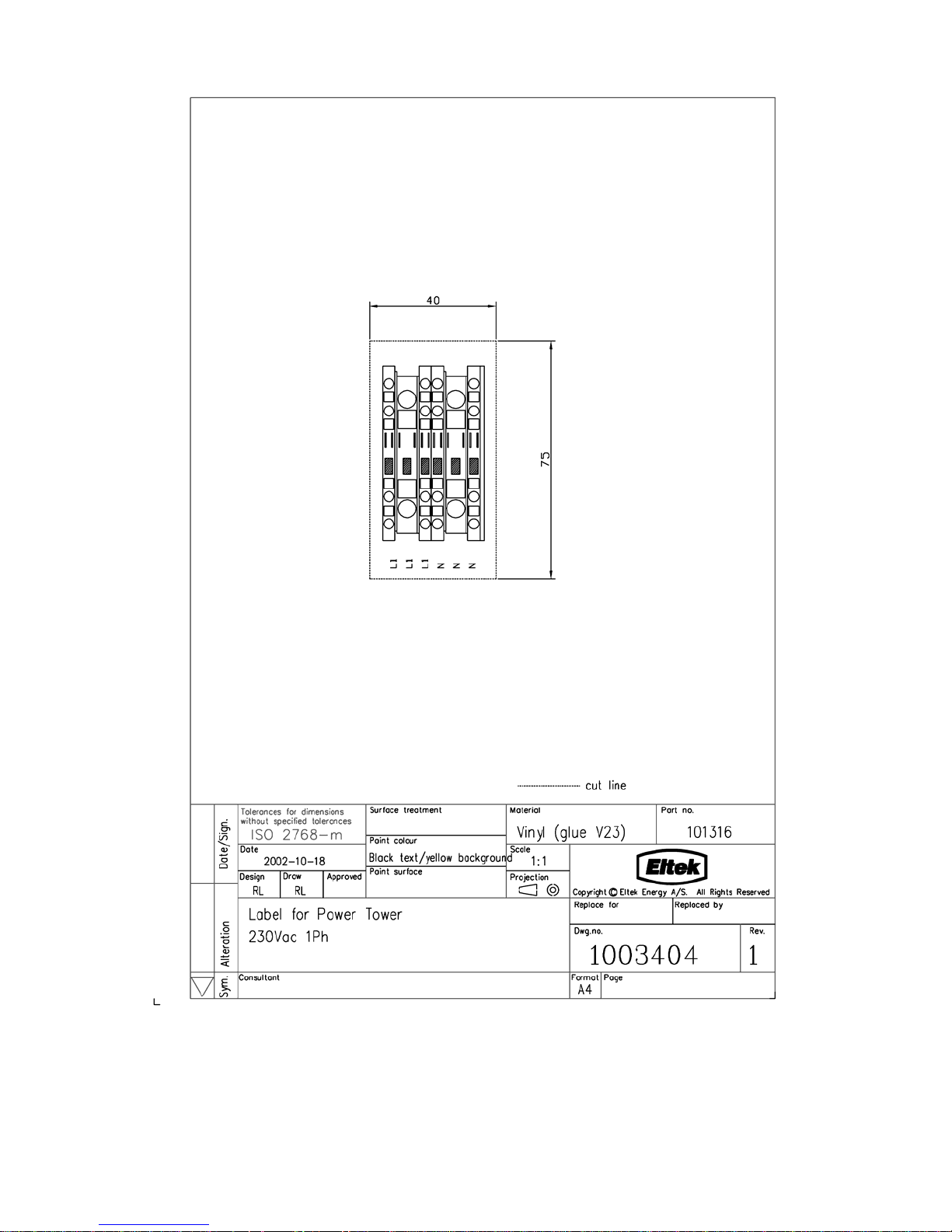
Figure 5 Label for Power Tower 230Vac 1Ph......................................................................................................... 40
Figure 6 Label for Power Tower 230Vac 3Ph......................................................................................................... 42
Figure 7 Label for Power Tower 400Vac 3Ph+N.................................................................................................... 44
Figure 8 General Assembly Drawing....................................................................................................................... 46
Operation Guide, Flatpack Power Tower
351401.013v2 July 2003
31(48)
8 Figures
Figure 1 Block Schematic, Flatpack Power Tower
32(48) Operation Guide, Flatpack Power Tower
351401.013v2 July 2003

8 Figures
Operation Guide, Flatpack Power Tower
351401.013v2 July 2003
33(48)
8 Figures
Figure 2 Schematic, 1Ph (230Vac)
34(48) Operation Guide, Flatpack Power Tower
351401.013v2 July 2003

8 Figures
Operation Guide, Flatpack Power Tower
351401.013v2 July 2003
35(48)
8 Figures
Figure 3 Schematic, 3Ph (230Vac)
36(48) Operation Guide, Flatpack Power Tower
351401.013v2 July 2003

8 Figures
Operation Guide, Flatpack Power Tower
351401.013v2 July 2003
37(48)
8 Figures
Figure 4 Schematic Power Tower, 3Ph +N (400Vac)
38(48) Operation Guide, Flatpack Power Tower
351401.013v2 July 2003

8 Figures
Operation Guide, Flatpack Power Tower
351401.013v2 July 2003
39(48)
8 Figures
Figure 5 Label for Power Tower 230Vac 1Ph
40(48) Operation Guide, Flatpack Power Tower
351401.013v2 July 2003

8 Figures
Operation Guide, Flatpack Power Tower
351401.013v2 July 2003
41(48)

8 Figures
Figure 6 Label for Power Tower 230Vac 3Ph
42(48) Operation Guide, Flatpack Power Tower
351401.013v2 July 2003

8 Figures
Operation Guide, Flatpack Power Tower
351401.013v2 July 2003
43(48)

8 Figures
Figure 7 Label for Power Tower 400Vac 3Ph+N
44(48) Operation Guide, Flatpack Power Tower
351401.013v2 July 2003

8 Figures
Operation Guide, Flatpack Power Tower
351401.013v2 July 2003
45(48)

8 Figures
Figure 8 General Assembly Drawing
46(48) Operation Guide, Flatpack Power Tower
351401.013v2 July 2003

8 Figures
Operation Guide, Flatpack Power Tower
351401.013v2 July 2003
47(48)

ELTEK Energy
P-O- BOX 2340 StØmsØ
N-3003 DRAMMEN
NORWAY
Phone: +4732203200
Telefax: +47 32203210
Internet: http://www.eltekenergy.com
e-mail: eltek@eltekenergy.com
 Loading...