

Page 1
Configuration Guide
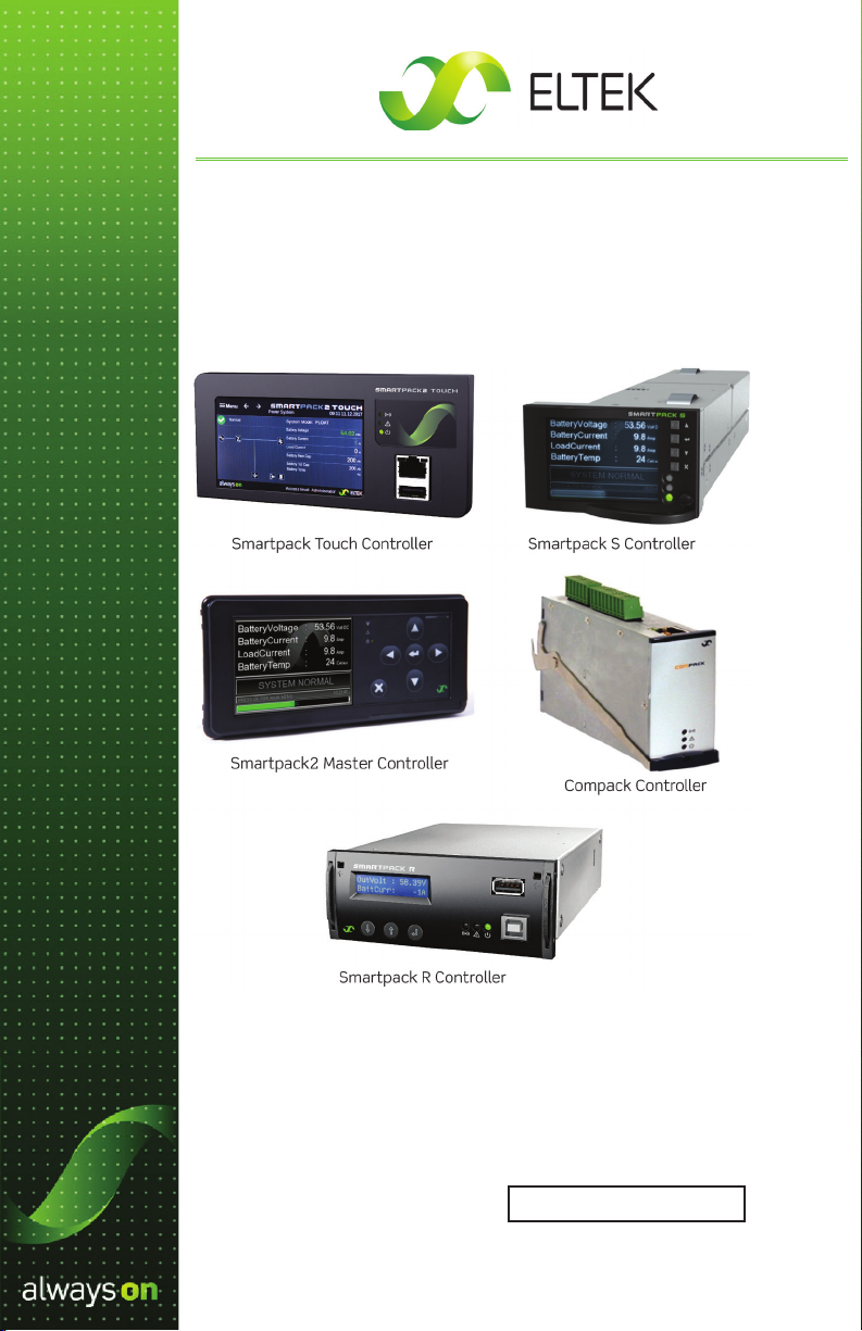
Eltek Controllers
Smartpack2, Smartpack S, Smartpack R, and
Compack
Doc. No. 370013.063, Issue 1.4
Published May 2022
Delta Part No. 5017152602
Page 2

DISCLAIMER
Information in this document is believed to be accurate as of the date of
publication and is subject to change without notice. This document and the
information contained herein do not represent either a commitment or any
guarantee on the part of Eltek regarding the reliability, fitness, or compatibility of
the products and procedures described.
While every reasonable eort is made to ensure the accuracy and completeness
of this document, Eltek assumes no responsibility or liability for any damages that
may be directly or indirectly attributed to the use of the information contained
within or to any errors or omissions.
No part of this document may be reproduced or transmitted in any form or by any
means – electronic or mechanical, including photocopying and recording – for any
purpose without the expressed consent of Eltek.
Copyright © 2012-2020 Eltek
2925 E. Plano Parkway
Plano, Texas 75074
USA
Phone: +1 (469) 330-9100
Fax: +1 (469) 330-9101
Technical Support
+1 (800) 435-4872
Customer Service and Sales Support
The latest version of this document and other Eltek product documents
are available online at eltek.sharefile.com.
+1 (469) 330-1592
www.eltek.com
Doc. No. 370013.063, Issue 1.4
Published May 2022
2 Configuration Guide: Eltek Controllers – Doc. No. 370013.063, Issue 1.4, May 2022
Page 3

Contents
1. Overview ........................................................................................5
Smartpack2 Touch ..........................................................................................5
Smartpack2 Master ........................................................................................6
Smartpack S .....................................................................................................6
Smartpack R .....................................................................................................7
Compack ............................................................................................................7
Passwords .........................................................................................................7
2. Direct Network Connection to the Controller ..............................8
Requirements ...................................................................................................8
Procedure ..........................................................................................................8
3. Setting Password Recovery .........................................................14
Setting Password Recovery Email Address ............................................ 14
Recovering/Resetting Master Password................................................. 15
4. Setting Float Voltage ..................................................................16
Setting Float Voltage through the
Browser Interface ......................................................................................... 16
Setting Float Voltage through the
Touch Screen (Smartpack Touch only) .................................................... 17
Setting Float Voltage through the Display Panel .................................. 20
5. Setting Battery Charging Current Limit .....................................22
Setting the Battery Charging Current Limit
through the Browser Interface .................................................................. 22
Setting the Battery Charging Current Limit
through the Display Panel........................................................................... 23
Configuration Guide: Eltek Controllers – Doc. No. 370013.063, Issue 1.4, May 2022 3
Page 4

6. Battery Temperature Monitoring.................................................25
Enabling Battery Temperature Input ........................................................ 25
Battery Temperature Compensation ...................................................... 30
7. Setting Battery Information ........................................................33
Enabling Battery Information through the Browser Interface ........... 33
Enabling Battery Information through the Display ............................... 34
8. Setting Battery Voltage Alarm ....................................................36
Setting Battery Voltage Alarm through the Browser Interface ........ 36
Setting Alarm Battery Voltage Alarm through the Display Panel ..... 37
9. Configuring Output Relay ...........................................................39
Output Alarm Relays .................................................................................... 40
Setting Output Relays through the Browser Interface ........................ 41
Setting Output Relays through the Display Panel ................................ 43
10. Alarm Relay Test ........................................................................45
Testing Output Relays through the Browser Interface ........................ 45
Testing Output Relays through the Display Panel ................................ 46
11. Setting Site Information ............................................................48
To Set Site Information through the Browser Interface ...................... 49
12. Configuration Backup ................................................................50
Overview ......................................................................................................... 50
Procedures ..................................................................................................... 51
4 Configuration Guide: Eltek Controllers – Doc. No. 370013.063, Issue 1.4, May 2022
Page 5

1. Overview
This configuration guide provides instructions for the following Eltek
controllers:
• Smartpack2 Touch
• Smartpack2 Master
• Smartpack S
• Smartpack R
• Compack
The procedures in this guide describe how to establish controller
communication using a computer and how to apply parameter
settings through various methods: the web browser interface, the
touch screen, and the display panel.
Unless otherwise noted, screenshots for the browser interface and
the display panel are taken from the Smartpack2 Master controller.
Additional details regarding particular controllers are given in the
following sections.
Smartpack2 Touch
The Touch Controller provides maximum flexibility. The Touch screen
can be used for direct monitoring, and to configure the controller. For
ease of use, a mouse and/or keyboard can be plugged into the USB
ports on the controller, in order to navigate and enter parameters
on the screen. If you prefer a larger screen, connect a computer to
the controller, using the Ethernet port on the face of the controller,
and utilize the same web browser interface employed by other
Eltek controllers. (See page 8 for instruction about connecting a
computer to the controller.)
Note: The Smartpack2 Touch screen uses the same basic interface
as the browser version, except that the Touch controller displays the
information in an adaptive format fitted to the smaller screen of the
controller. The main navigational dierence is that the left menu bar
in the browser interface becomes a sub-menu in the Touch interface;
the submenu must be accessed first on the Touch display, in order
to select the associated configuration options. The configuration
options are the same as the browser interface, although you may
have to scroll further down a page to see all the options.
Configuration Guide: Eltek Controllers – Doc. No. 370013.063, Issue 1.4, May 2022 5
Page 6
In order to see the dierences between the Smartpack Touch
screen interface and the browser interface, study the instructions in
“Setting Float Voltage” on page 16. Subsequent chapters assume
that you understand the adaptive dierences in appearance between
the browser and the screen.
Smartpack2 Master
For the Smartpack2 Master controller, setup can be performed
through either the browser interface or display panel.
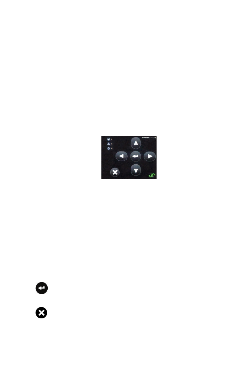
NOTE: The Smartpack2 Master controller display must be unlocked
in order to enter the Main Menu. At the default status screen, press
the UP arrow key, DOWN arrow key, and then the ENTER key to unlock
the screen and enter the Main Menu.
Figure 1 – Smartpack 2 Master Navigation Buttons
Smartpack S
For the Smartpack S controller, setup can be performed through
either the browser interface or display panel.
NOTE: The Smartpack S controller’s navigation keys are slightly
dierent from the Smartpack2 controller’s keys in that the ENTER
and CANCEL (X) keys also function as the LEFT and RIGHT keys,
respectively, as follows:
ENTER: A short press of this key navigates to the LEFT. A long
press (or, “press-and-hold”) performs an ENTER or confirm
action.
CANCEL (X): A short press of this key navigates to the RIGHT.
A long press performs a CANCEL or abort action.
6 Configuration Guide: Eltek Controllers – Doc. No. 370013.063, Issue 1.4, May 2022
Page 7
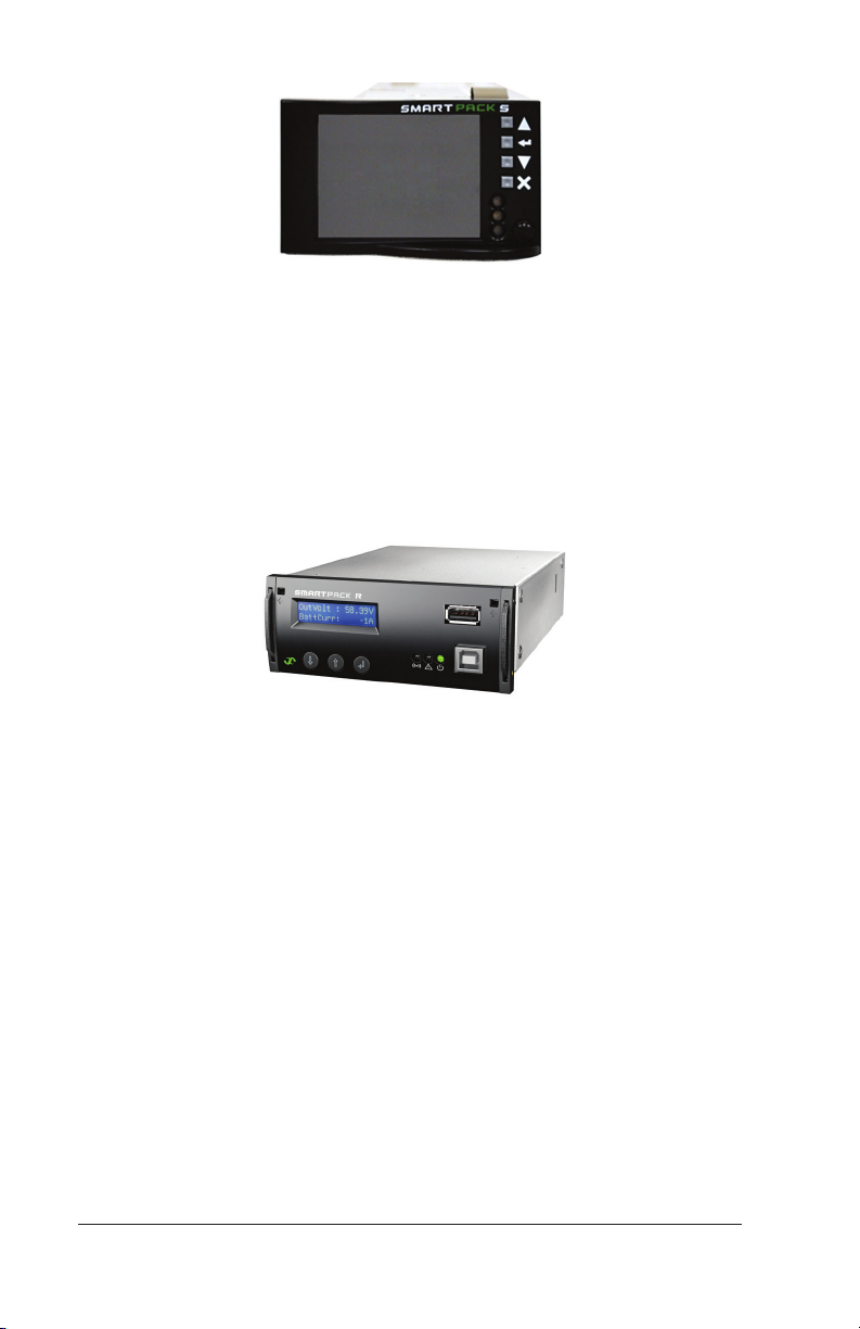
Figure 2 – Smartpack S Controller Navigation Buttons
Smartpack R
The Smartpack R controller has a unique display panel; it also
employs the browser interface to adjust parameters. Use the
instructions for the browser interface when performing the tasks
described in this guide. For additional information about the
Smartpack R display, and other features, see the User's Guide:
Smartpack R Controller (Doc. No. 350166.013).
Figure 3 – Smartpack R Controller
Compack
The Compack controller does not have a display panel and therefore
requires the use of a computer and an Ethernet connection for the
browser interface in order to adjust parameters.
Passwords
Passwords are required to edit fields and apply changes. The
following are the default passwords for each interface:
• Browser or Touch interface: The administrative password re-
quired to make changes is entered when logging in to the interface. By default, the credentials are:
User name: admin
Password: admin
• Display: The administrative password (PIN, in this case) is entered
when selecting a field to edit. By default, the PIN is 0003.
Configuration Guide: Eltek Controllers – Doc. No. 370013.063, Issue 1.4, May 2022 7
Page 8

2. Direct Network Connection to
the Controller
The following procedure describes the most reliable method for
establishing a direct connection between a computer and an
Eltek controller, which facilitates access through the web browser
interface.
Requirements
Before connecting to and accessing an Eltek controller by computer,
the following items and information must be collected:
• Make sure the User Guides for the controller and system are on
hand. If not, please visit the Eltek ShareFile site (https://eltek.
sharefile.com) and download the appropriate documents.
• Install the Eltek Network Utility (ENU) on the computer to be
used. This utility can be downloaded from the Internet (http://
msm.eltek.com/enu).
• The web browser interface is tested using Microsoft® Internet
Explorer®, Mozilla® Firefox®, and Google Chrome® for Windows.
• IMPORTANT: The following Eltek interfaces require the computer
ports specified to be available (i.e., not blocked by the local network administration or IT group):
• Eltek Network Utility:
UPD port 20034
TCP port 80
• Web Browser Interface:
TCP port 80
TCP port 443
Procedure
1. Use an Ethernet cable (either cross-over or straight-through) to
connect a computer to the controller.
8 Configuration Guide: Eltek Controllers – Doc. No. 370013.063, Issue 1.4, May 2022
Page 9
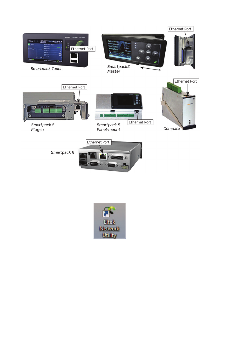
Figure 4 – Controller Ethernet Ports
2. Launch the Eltek Network Utility (ENU) on the computer.
Figure 5 – Eltek Network Utility Icon
Note: If using a Smartpack2 Touch controller, and ENU is not
installed, you can plug directly into the Ethernet port on the face
of the controller. This port is a “craft port” for direct computerto-controller access. After plugging into this port on a Touch
controller, open a browser, enter the address 10.10.0.1, and move
to step 6.
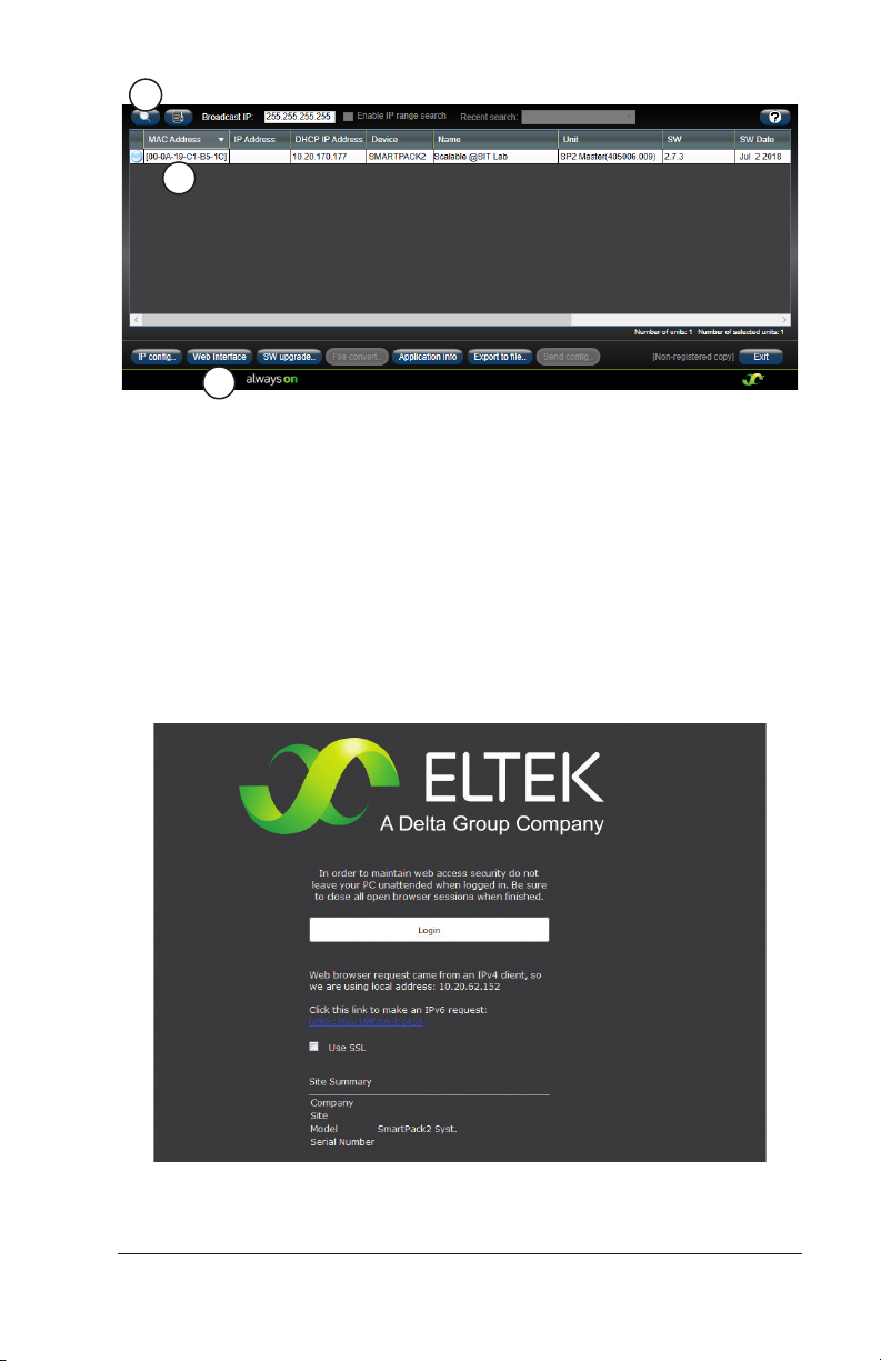
3. After the ENU program opens, click on the search button (magnifying glass button) in the upper left corner to find the controller.
Wait for the window to populate.
Configuration Guide: Eltek Controllers – Doc. No. 370013.063, Issue 1.4, May 2022 9
Page 10
3
4
5
Figure 6 – Eltek Network Utility Window
4. Click on the controller line to select it.
NOTE: By default, Eltek controllers are shipped with a static
IP address of 192.168.10.20. (For the Touch controller, this
address only applies to the rear port, not the port on the face.)
5. Click on the Web Interface button.
6. Does the Login page appear in the web browser? (See the following figure.)
Figure 7 – Web Browser Interface Login Page
10 Configuration Guide: Eltek Controllers – Doc. No. 370013.063, Issue 1.4, May 2022
Page 11

• If YES, then skip to step 20 (on page 13).
• If NO, then the controller’s IP address must be changed to
be closer to the IP address of the computer. Continue to the
next step.
7. On the computer, launch a Command Prompt window. This can
be done in one of two ways:
• Click the Start button, choose Run, type cmd in the text field,
and click the OK button.
• Click the Start button, choose All Programs, select
Accessories, and then select Command Prompt.
Figure 8 – Command Prompt Window
8. At the command prompt, type ipconfig and press [ENTER]. A
series of lines appears listing all of the TCP/IP identities of the
computer.
9. Find the heading Ethernet adapter Local Area Connection (or similar text); it may be necessary to scroll upwards in the command
prompt window. Locate the IPv4 address line and write down or
copy the address. It consists of four sets of numbers separated
by three periods (in the form xxx.xxx.xxx.xxx). This address is
needed in step 15 (on page 12).
10. Type exit at the prompt to close the Command Prompt window.
11. In the ENU program, select the controller and click on the IP
Config… button. The Ip configuration window appears.
Configuration Guide: Eltek Controllers – Doc. No. 370013.063, Issue 1.4, May 2022 11
Page 12
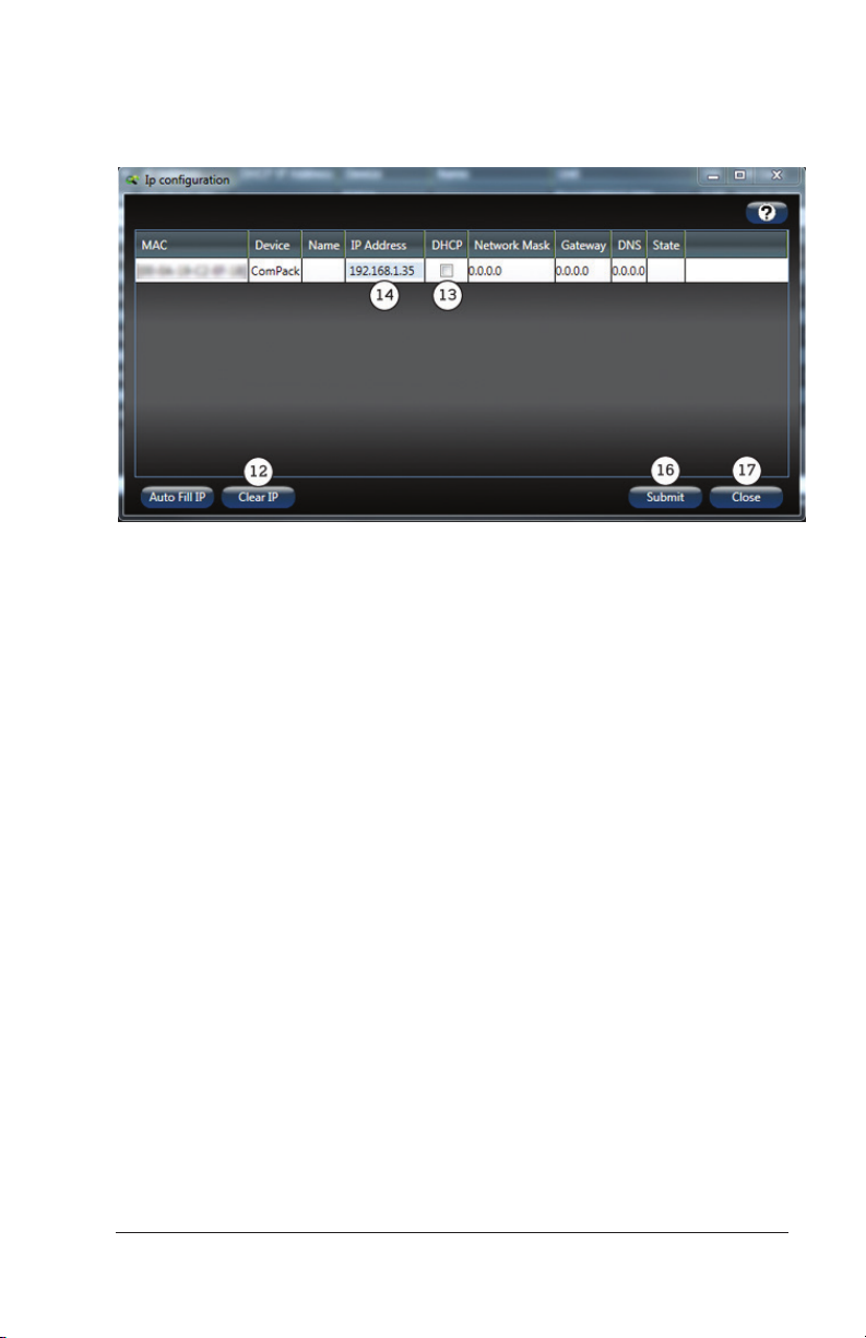
12. Click on the Clear IP button.
13. Make sure the check box under DHCP is NOT checked (empty).
Figure 9 – Ip Configuration Window
14. Click in the field under IP Address until the box is highlighted and
a cursor appears.
15. Type an address that is close to the IP address of the computer.
The first three numbers (or octets) should be exactly the same
to ensure that both the computer and controller are on the same
network; the last number (octet) should be dierent by a few
digits.
For example, if the computer’s IPv4 address is 192.168.1.30, then
use the first three numbers (192.168.1) exactly as they appear
for the controller. For the last number, pick something close to
the computer’s last number, like 35. The resulting IP address for
the controller in this example will be 192.168.1.35.
NOTE: If an invalid address is entered, the box shows a red outline. Leading zeros should be omitted.
16. Click the Submit button. There may be a “click” from the controller as it reboots to apply the new IP address. Allow 30 seconds
for the controller to finish the reboot cycle.
17. Click the Close button of the Ip configuration window.
18. After the controller reboots, return to the main window of the
ENU program and click the search button again. The controller
appears in the list with the new IP address.
12 Configuration Guide: Eltek Controllers – Doc. No. 370013.063, Issue 1.4, May 2022
Page 13
19. Select the controller and click the Web Interface button. The
login page appears (as shown in step 6, on page 10).
20. Click the LOGIN link.
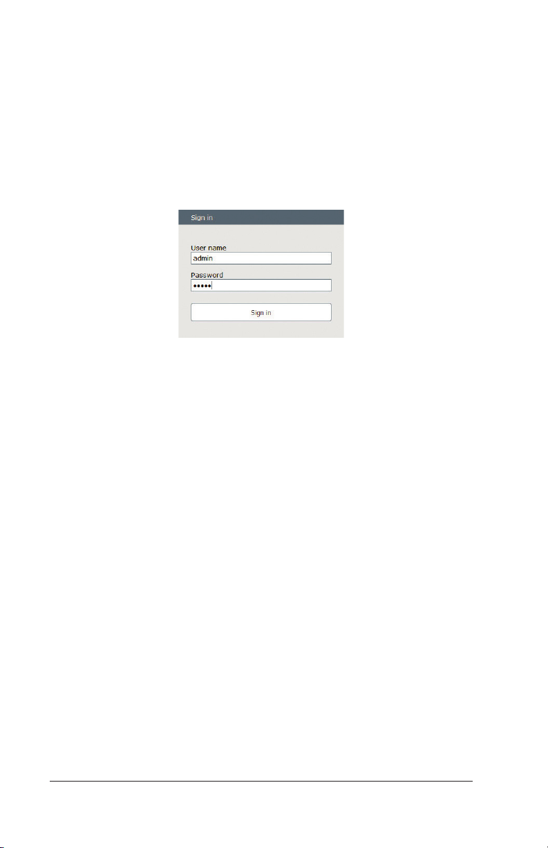
21. At the prompt, type in the username and password. The defaults
are:
Username: admin
Password: admin
Figure 10 – Sign In Prompt
NOTE: The username and password are case-sensitive. If these
credentials do not work, then they have been changed on site.
Consult site personnel and/or site documentation for the current
credentials.
Controller connection is now established. Make sure to logout from
the controller when you are finished.
NOTE: If the controller is to be connected to a local area network
(LAN), contact the local network administrator to determine if a
static IP address is to be assigned or if the IP address will be assigned
dynamically (DHCP). Use the “Ip configuration” window to set the
controller IP configuration according to the instructions from the
network administrator. Refer to steps 11 – 17 again, if necessary.
RECOMMENDATION: If connecting the controller to a LAN after
setup, make sure to check connectivity through the network!
For controllers with a display (Smartpack2, Smartpack S), the
controller’s IP address can be found at the following location:
Main Menu > Sys.Config. > PowerSystem > General System
Config. > Agent IP Address
Configuration Guide: Eltek Controllers – Doc. No. 370013.063, Issue 1.4, May 2022 13
Page 14
3. Setting Password Recovery
This Password Recovery feature applies to the Smartpack Touch and
Smartpack R controllers, using the web browser interface.
Setting a Password Recovery Email Address
When configuring a controller with this feature, be sure to enter
a password recover email address. Failure to provide a recovery
address makes the recovery process unavailable, in some cases
requiring the return of the controller to Eltek for reprogramming.
To set a password recovery address:
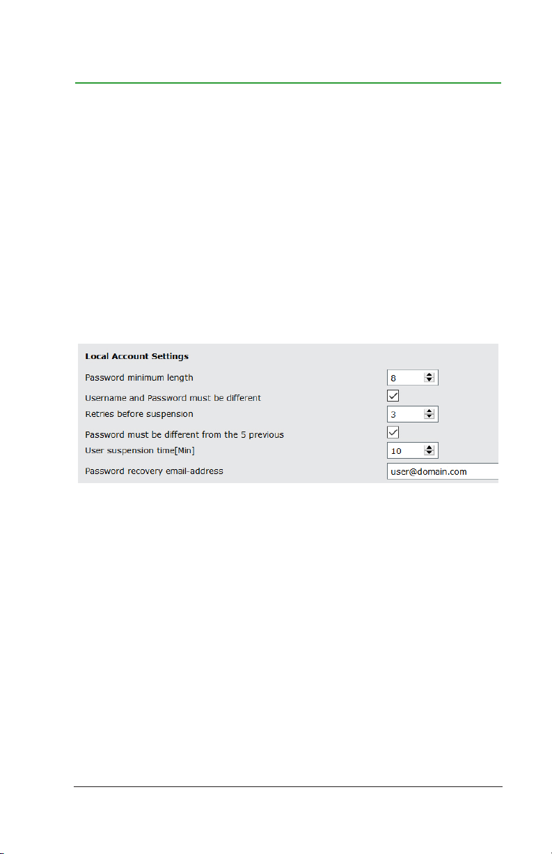
1. Go to System Conf. > Device Settings > Local Accounts.
Figure 1 – Setting Password Recovery Email Address
2. In the text field, Password recovery email address, enter the
email address to which you want a recovery link sent, in a case
where the password must be recovered.
Note: Check the spelling of the email address carefully. Also remember to keep this field current, if there are changes in your
company email system or personnel. This address must be entered during configuration; it cannot be set after the password
has already been lost.
For instructions on how to recover/reset the password, see the next
section, “"Recovering/Resetting the Master Password".”
14 Configuration Guide: Eltek Controllers – Doc. No. 370013.063, Issue 1.4, May 2022
Page 15
Recovering/Resetting the Master Password
To recover/reset your Master Password:
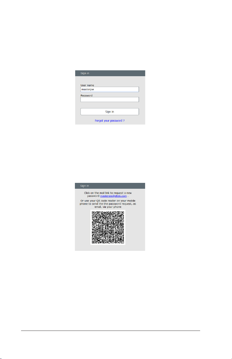
1. On the Sign in window, for the User name, enter masterpw, press
the Tab key, and click Forgot your password. A new page will ap-
pear, with options for generating a reset link.
Figure 2 – Sign In for Password Recovery
2. On the link request page, do one of the following:
• Click on the mail link. The link produces a special email message,
using your default email application; send the message.
• Use a cell phone with a QR-code reader, and scan the code. The
QR code produces a special email message; send the message.
Figure 3 – Generating Email Recovery Message
3. Check the email for the address associated with password recovery. (This is the email address entered in System Conf. > Device
Settings > Local Accounts, as covered in the previous section,
“"Setting a Password Recovery Email Address".” Follow the instructions given in the email.
For additional details, see the User Guide: Eltek Controller Web
Interface (Doc. No. 370035.013).
Configuration Guide: Eltek Controllers – Doc. No. 370013.063, Issue 1.4, May 2022 15
Page 16
4. Setting Float Voltage
CAUTION: Refer to the battery manufacturer’s documented
specifications for recommended float voltage per battery
cell. It is the user’s responsibility to enter proper battery
parameters.
NOTE: Float voltage is calculated based on the voltage required per
battery cell.
Setting Float Voltage through the
Browser Interface
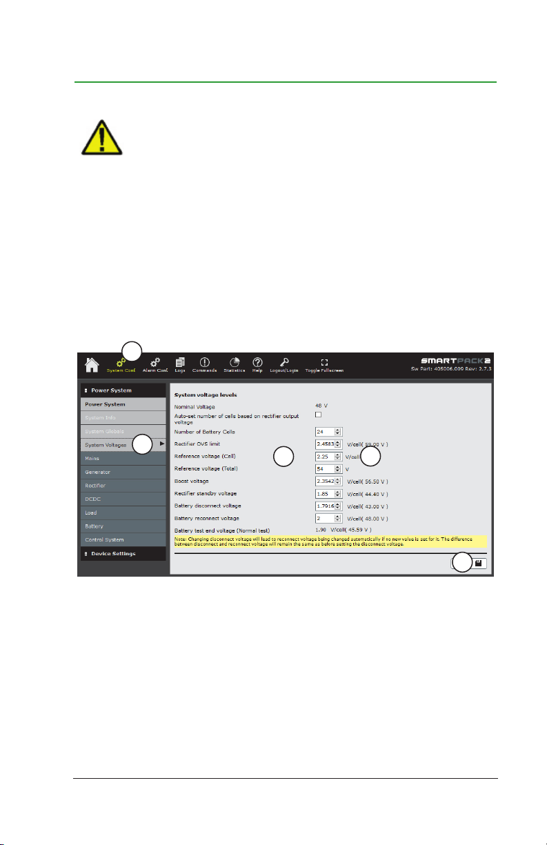
To set float voltage through the browser interface:
1
2
3
Figure 1 – Setting Float Voltage Using the Browser Interface
1. Click on the System Conf. button in the top menu bar.
2. In the left menu bar, click on the System Voltages button (below
the Power System heading).
3. Locate the field called Reference voltage (Cell).
4
5
16 Configuration Guide: Eltek Controllers – Doc. No. 370013.063, Issue 1.4, May 2022
Page 17
4. Enter the voltage per cell required.
Alternately, you can enter total reference voltage in the
corresponding field, Reference voltage (Total), and the per cell
voltage adjusts automatically.
5. Click the diskette button (in the lower right-hand corner) to save
the change. The voltage value in parentheses updates to reflect
the new float voltage value.
Setting Float Voltage through the
Touch Screen (Smartpack Touch only)
To set float voltage through the Touch screen:
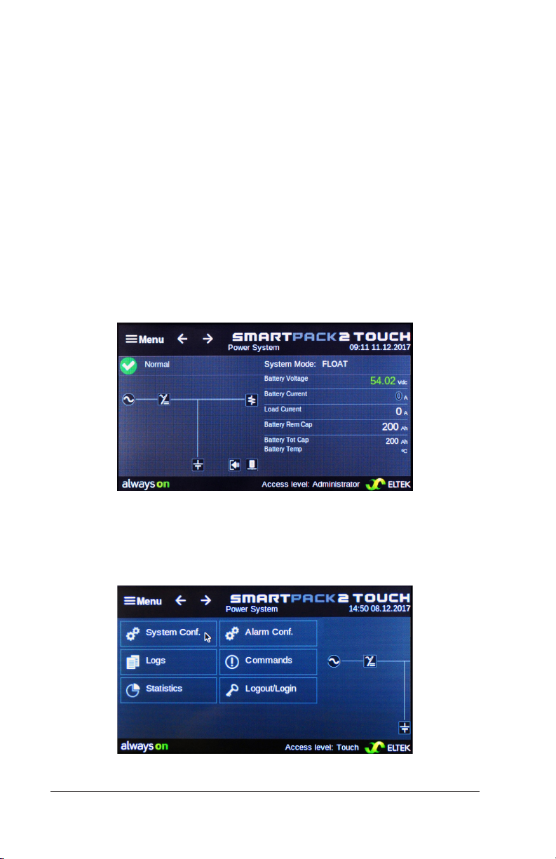
1. On the home menu, choose Menu in the upper left corner.
Figure 2 – Touch Controller Home Menu
2. If you have not yet logged in, choose Logout/Login. After you
have logged in, choose System Config.
Figure 3 – Touch Controller Main Menu
Configuration Guide: Eltek Controllers – Doc. No. 370013.063, Issue 1.4, May 2022 17
Page 18
Note: If you have not already logged in as administrator, you must
do so before you can make changes to the controller configuration. To log in, choose the Logout/Login option from the icons
screen. As with the browser interface, the log in defaults are:
Username: admin
Password: admin
After logging in, go back and choose System Config. This selec-
tion takes you to the top page in the System Config. category (in
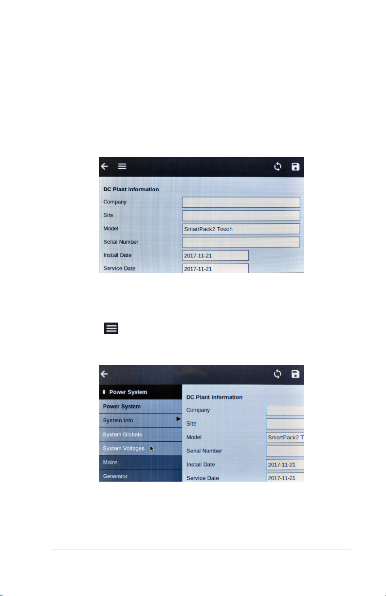
this case the Power System page or DC Plant Information).
Figure 4 – DC Plant Information Page
3. From the DC Plant Information page (Figure 4), Choose the Menu
button ( ) to move to the full list of Power System menu
(Figure 5). This list corresponds to the left column of the browser
interface.
Figure 5 – Power System Menu
Note: Compare the Figure 5 with Figure 1 above, to see the
parallels between this Touch submenu and the left navigation
18 Configuration Guide: Eltek Controllers – Doc. No. 370013.063, Issue 1.4, May 2022
Page 19
column in the browser interface. From this point forward, the
options and instructions for the Touch screen parallel the options
on the browser interface, although you may have to scroll down
the page further, in order to see all the parameters. When setting
additional parameters using the Touch screen, follow a procedure
corresponding to these first three steps in order to navigate to
the submenus for specific parameters. The general instructions
for the browser interface, in the successive chapters, can be used
to configure the same parameters using the Touch screen.
4. Choose System Voltages, below the Power System heading (see
Figure 5).
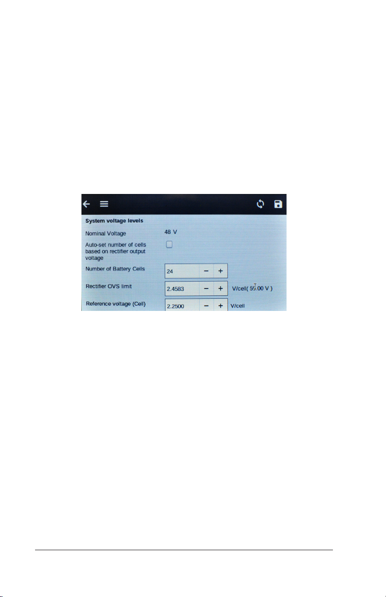
5. Locate the field called Reference voltage (Cell).
Figure 6 – System Voltage Levels Menu
6. Enter the voltage per cell required.
Alternately, you can enter total reference voltage in the
corresponding field, Reference voltage (Total), and the per cell
voltage adjusts automatically.
7. Click the Save diskette button in the upper right-hand corner to
save the change. The voltage value in parentheses updates to
reflect the new float voltage value.
Note: The standard position for the Save button on the Touch
screen is in the upper right corner, as compared to the browser
interface, where he Save button is routinely placed in the lower
right corner.
Configuration Guide: Eltek Controllers – Doc. No. 370013.063, Issue 1.4, May 2022 19
Page 20
Setting Float Voltage through the Display
Panel
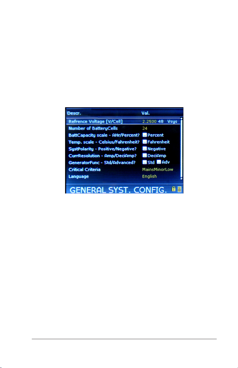
To set float voltage (volts per cell) through the display panel:
1. From the Main Menu, select Sys. Config.
2. Select Power System.
3. Select General System Config.
This selection opens the GENERAL SYST. CONFIG. screen.
Figure 7 – Setting Float Voltage Using the Display Panel
4. Select Reference Voltage [V/Cell].
5. Enter the PIN. The default PIN is 0003.
6. Enter the float voltage desired per cell.
7. Press the [ENTER] key to save the change.
The float voltage is now set.
Alternately, you can enter total float voltage using the System
Voltages section of the display; using this method, the per cell
voltage adjusts automatically.
20 Configuration Guide: Eltek Controllers – Doc. No. 370013.063, Issue 1.4, May 2022
Page 21
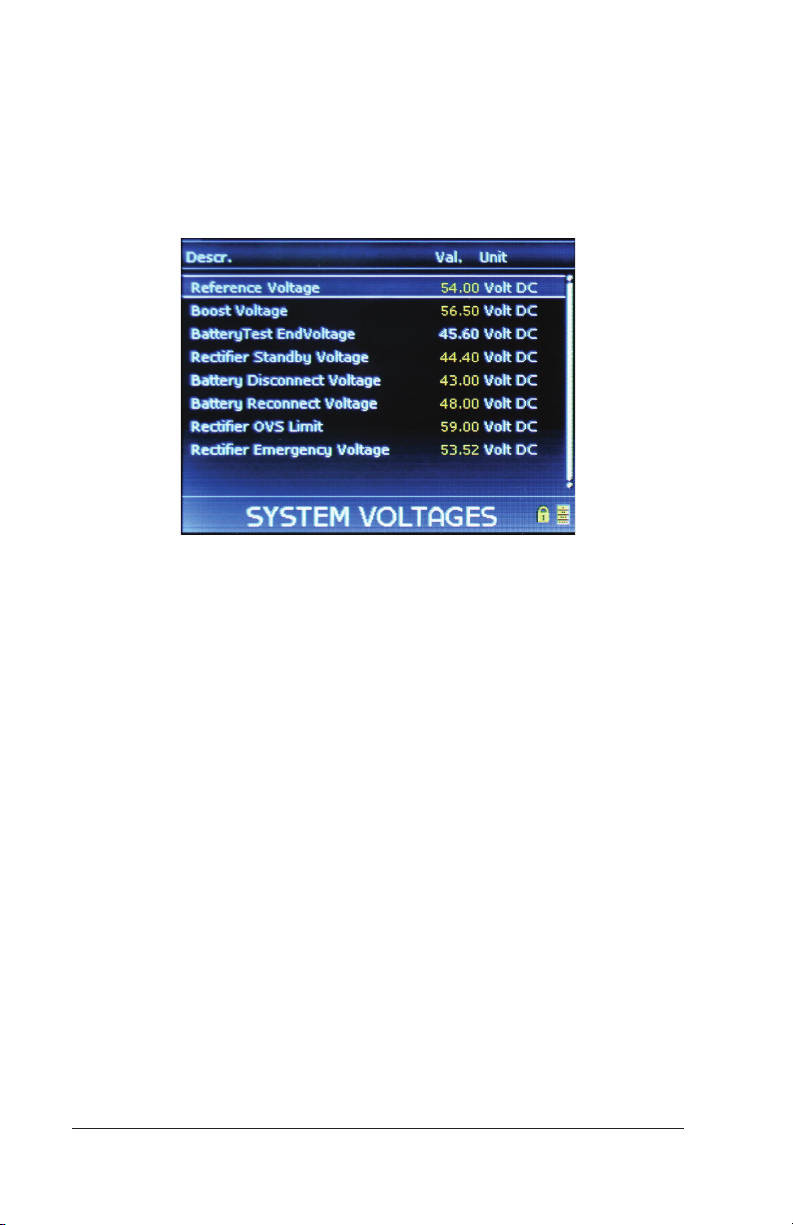
To set total float voltage:
1. From the Main Menu, select Sys. Config.
2. Select Power System.
3. Select System Voltages.
Figure 8 – Setting System Float Voltage Using the Display Panel
4. Select Reference Voltage.
5. Enter the PIN. The default PIN is 0003.
6. Enter the total float voltage; the per cell voltage adjusts automatically.
Configuration Guide: Eltek Controllers – Doc. No. 370013.063, Issue 1.4, May 2022 21
Page 22
5. Setting Battery Charging Current
Limit
Battery current limit restricts charge current. Eltek controllers
have two separate current limit parameters for dierent power
situations: Mains (normal AC utility service) and Generator (AC
backup). Generator current limit is only necessary if you are using
theSmartpack2 controller to control your generator.
NOTE: A shunt is required in order to use battery current limit.
Setting the Battery Charging Current Limit
through the Browser Interface
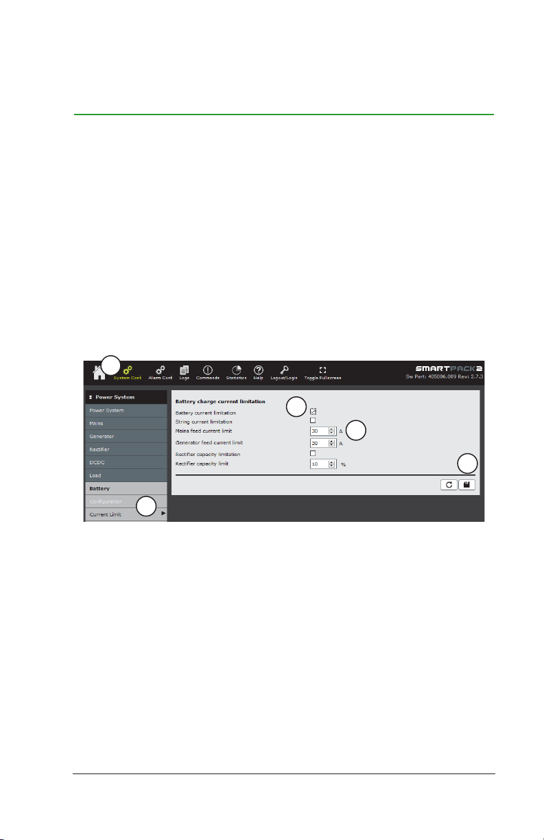
To set battery charging current limit through the browser interface:
1
3
4
5
2
Figure 1 – Setting Battery Charging Current Limit Using the Browser Interface
1. Click on the System Conf. icon in the top menu bar.
2. In the left menu bar, click on Battery button (below the Power
System heading), then choose Current Limit.
3. To turn on battery current limit, check the box next to Battery
current limitation.
4. To set current limit values, enter the prescribed maximum current
value in the fields for Mains feed current limit (normal AC service)
and Generator feed current limit (if applicable; check site and
generator specifications).
22 Configuration Guide: Eltek Controllers – Doc. No. 370013.063, Issue 1.4, May 2022
Page 23
NOTE: Normally the value for Generator feed current limit
is lower than Mains feed current limit. If the Generator feed
current limit is not going to be used, then simply put the same
value here as the Mains feed current limit.
5. Click the diskette button to save changes.
Setting the Battery Charging Current Limit
through the Display Panel
To set battery charging current limit through the display panel:
1. From the Main Menu, select Sys. Config.
2. Select Battery.
3. Select Battery Config. This selection opens the BATTERY
CONFIG. screen.
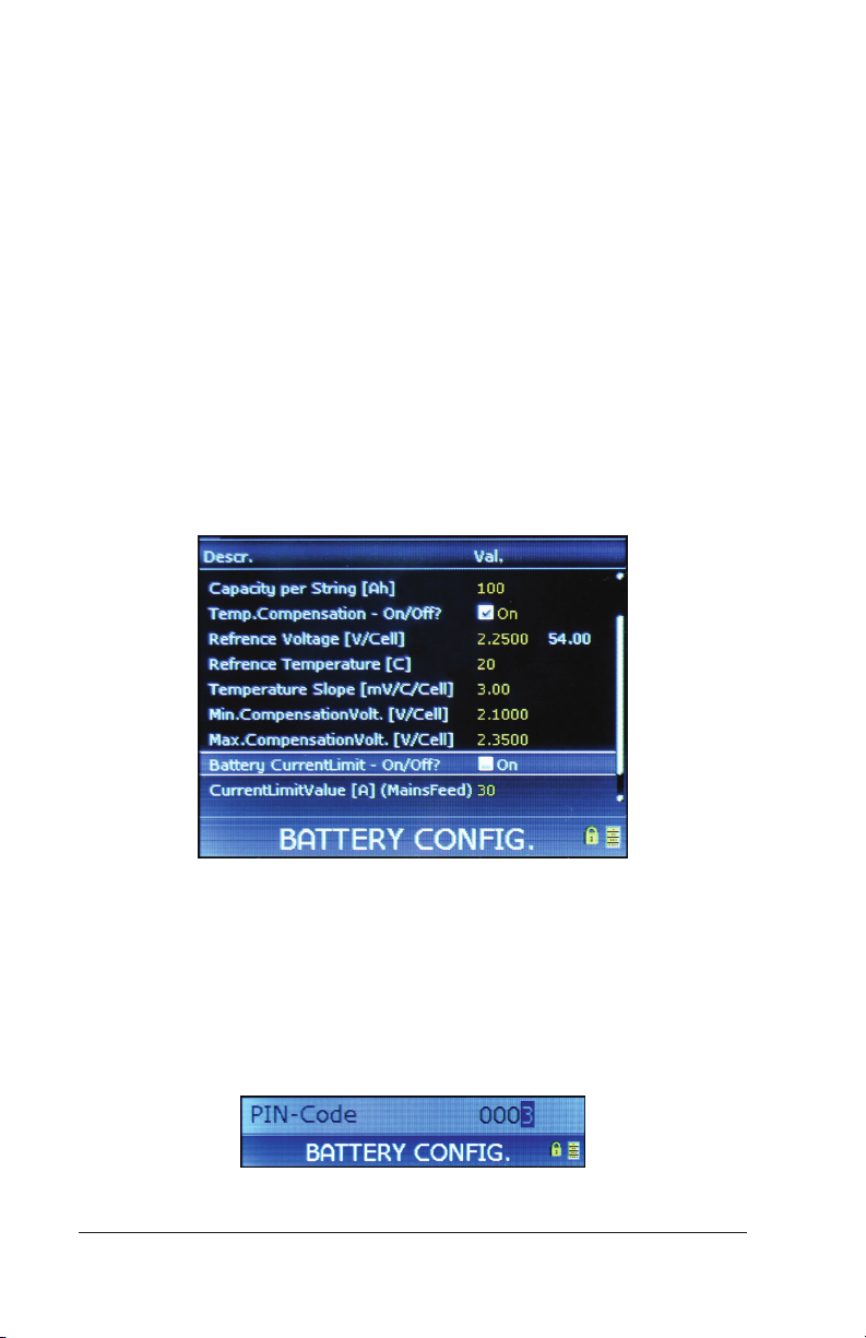
Figure 2 – Setting Battery Charging Current Limit Using the Display Panel
4. Scroll down to Battery CurrentLimit - On/O? and press [ENTER]
to select it.
5. Use UP and DOWN arrow keys to enter the PIN (default PIN is
0003). Press [ENTER] to accept. (Press and hold [ ENTER] for
Smartpack S.)
Figure 3 – Entering PIN
Configuration Guide: Eltek Controllers – Doc. No. 370013.063, Issue 1.4, May 2022 23
Page 24
6. Use the UP or DOWN arrow keys to place a check mark in the box.
7. Press the [ENTER] key to save the change.
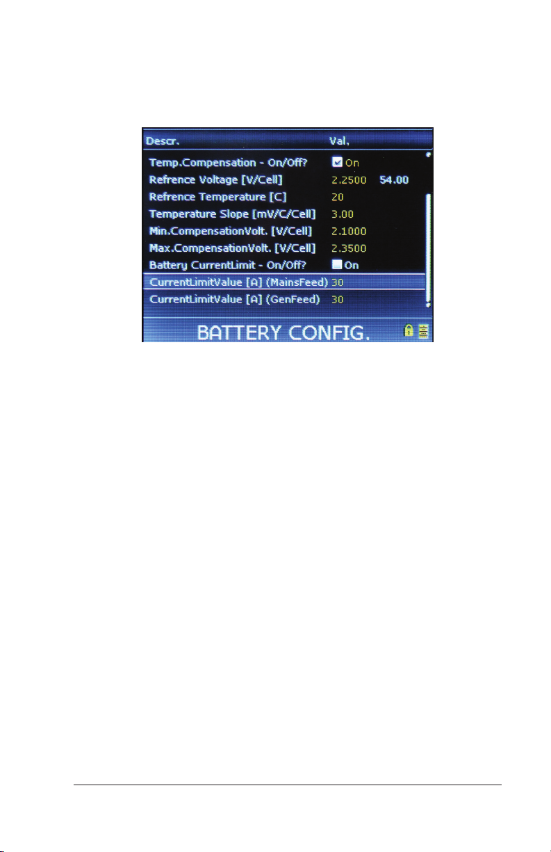
8. Scroll down to select CurrentLimitValue [A] (MainsFeed).
Figure 4 – Current Limit Value (Mains)
9. Enter the current value desired for when the system is on regular
AC utility service.
10. Press the [ENTER] key to save the change.
11. If a current limit setpoint is desired for AC generator power,
then scroll down to CurrentLimitValue [A] (GenFeed) and press
[ENTER] to select it.
NOTE: Normally the value for Generator feed current limit is
lower than Mains feed current limit. If the Generator feed current
limit is not going to be used, then simply put the same value here
as the Mains feed current limit.
12. Enter the current value desired for when the system is on AC
generator back-up.
13. Press the [ENTER] key to save the change.
Battery charging current limit is now set.
14. Exit to the home screen.
24 Configuration Guide: Eltek Controllers – Doc. No. 370013.063, Issue 1.4, May 2022
Page 25
6. Battery Temperature Monitoring
Battery temperature monitoring is covered in the following sections:
• “Enabling Battery Temperature Probe” (below)
• "Battery Temperature Compensation" on page 30
Enabling Battery Temperature Input
Battery temperature inputs are disabled from the factory. If you
connect temperature probes to the controller (Smartpack2 Basic,
Smartpack2 Basic Industrial, Smartpack S, Compack), you must
enable the input, in order to trigger battery temperature alarms or
activate temperature compensation. Battery temperature alarms
may be set for individual inputs or as a group of inputs.
Note: If you are using a CAN Node external device (such as the
Battery Monitor or FlexiMonitor) for monitoring battery temperature,
consult the instructions that came with your device.
Enabling Battery Temperature Input through the
Browser Interface
To enable the battery sensor through the browser interface:
1
3
2
4
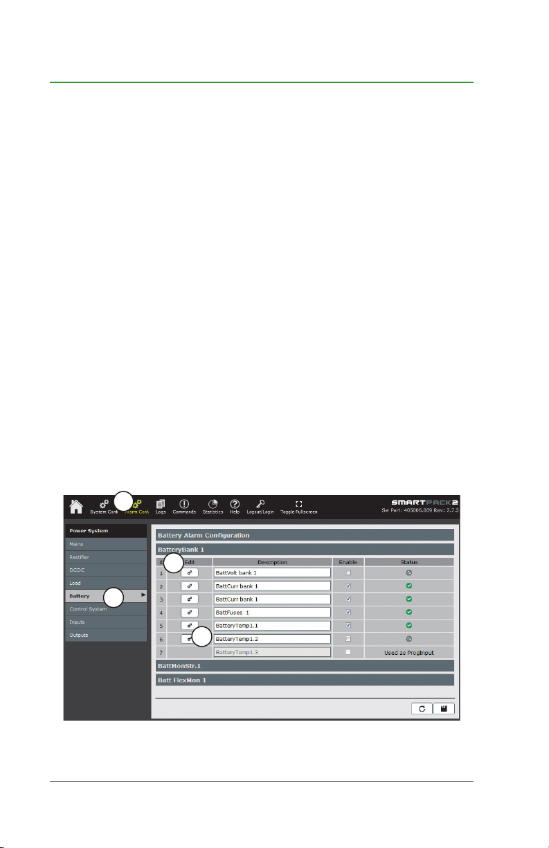
Figure 1 – Setting Battery Temperature Probe Using the Browser Interface
Configuration Guide: Eltek Controllers – Doc. No. 370013.063, Issue 1.4, May 2022 25
Page 26
1. Click on the Alarm Config icon on the top menu bar.
2. In the left menu bar, click on the Battery button.
3. Click on the BatteryBank1 tab.
4. On BatteryBank1 tab, Click edit button for BatteryTemp1.x
(where x is the input number for the temperature probe connection).
5. On BatteryTemp1.x dialog, check Enable.
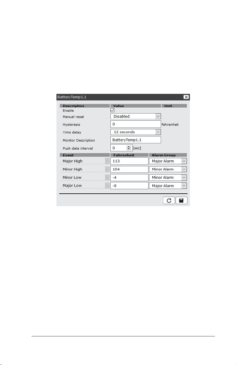
Figure 2 – Setting Battery Temperature Probe Using the Browser Interface
6. Change alarm settings if desired.
Note: These alarm settings apply only to the specific input (for
example, BatteryTemp1.1). If you do not want an alarm for this
specific input, set the temperature values outside of the expected range.
7. Save your changes (diskette button), and exit the Battery Temp
1.x dialog.
8. Repeat steps 4-7 for additional inputs.
Note: To apply alarm settings to all Battery Temperature inputs,
continue with the additional following steps.
26 Configuration Guide: Eltek Controllers – Doc. No. 370013.063, Issue 1.4, May 2022
Page 27
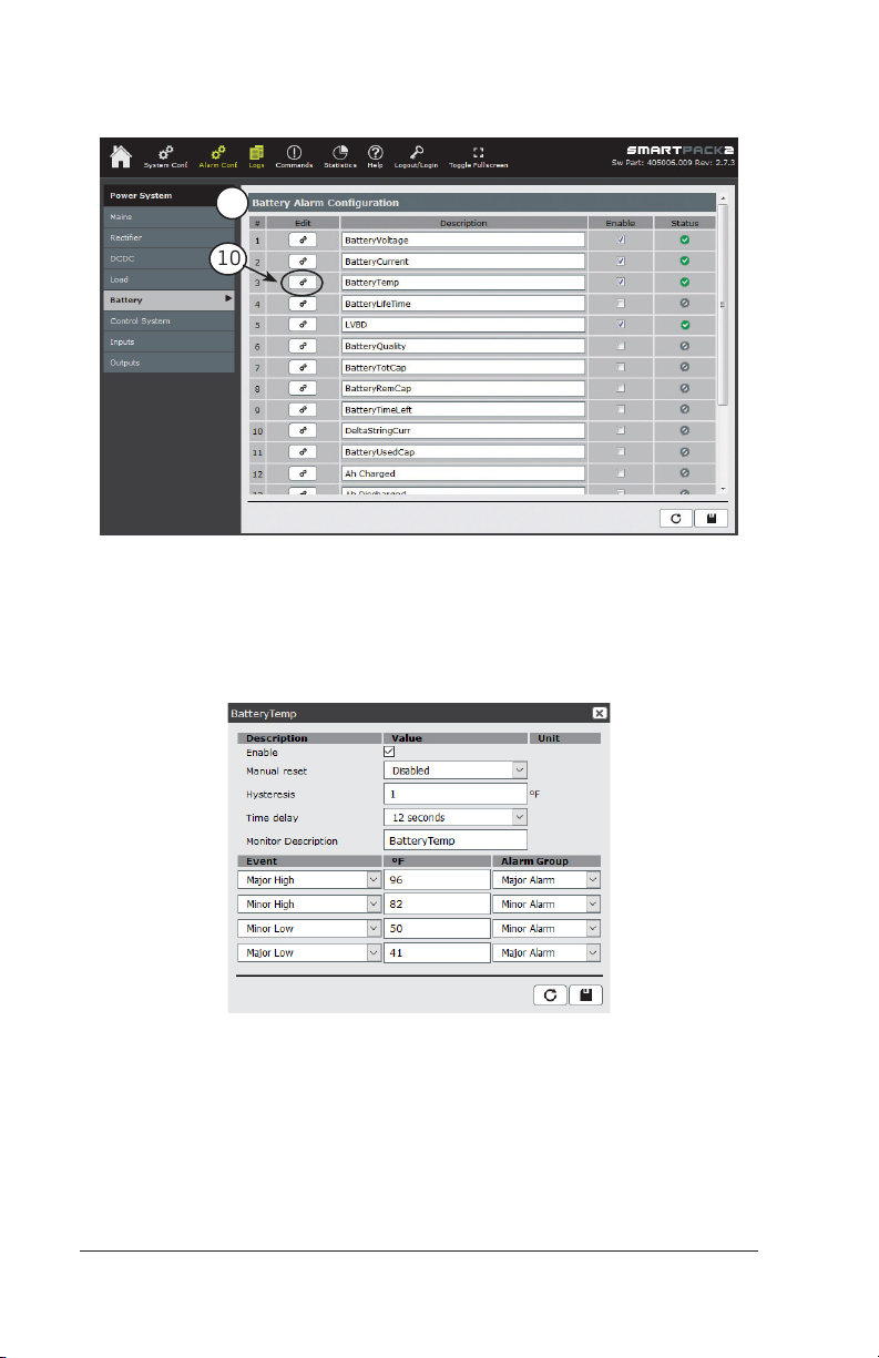
9. To set parameters for all Battery Temperature inputs, begin by
choosing the Battery Alarm Configuration tab.
9
10
Figure 3 – Setting All Battery Temperature Inputs
10. Click the Battery Temp edit button (gears).
11. On the Battery Temp dialog, set the desired parameters.
Figure 4 – BatteryTemp Parameters
12. Save your changes (diskette button), and exit.
Configuration Guide: Eltek Controllers – Doc. No. 370013.063, Issue 1.4, May 2022 27
Page 28
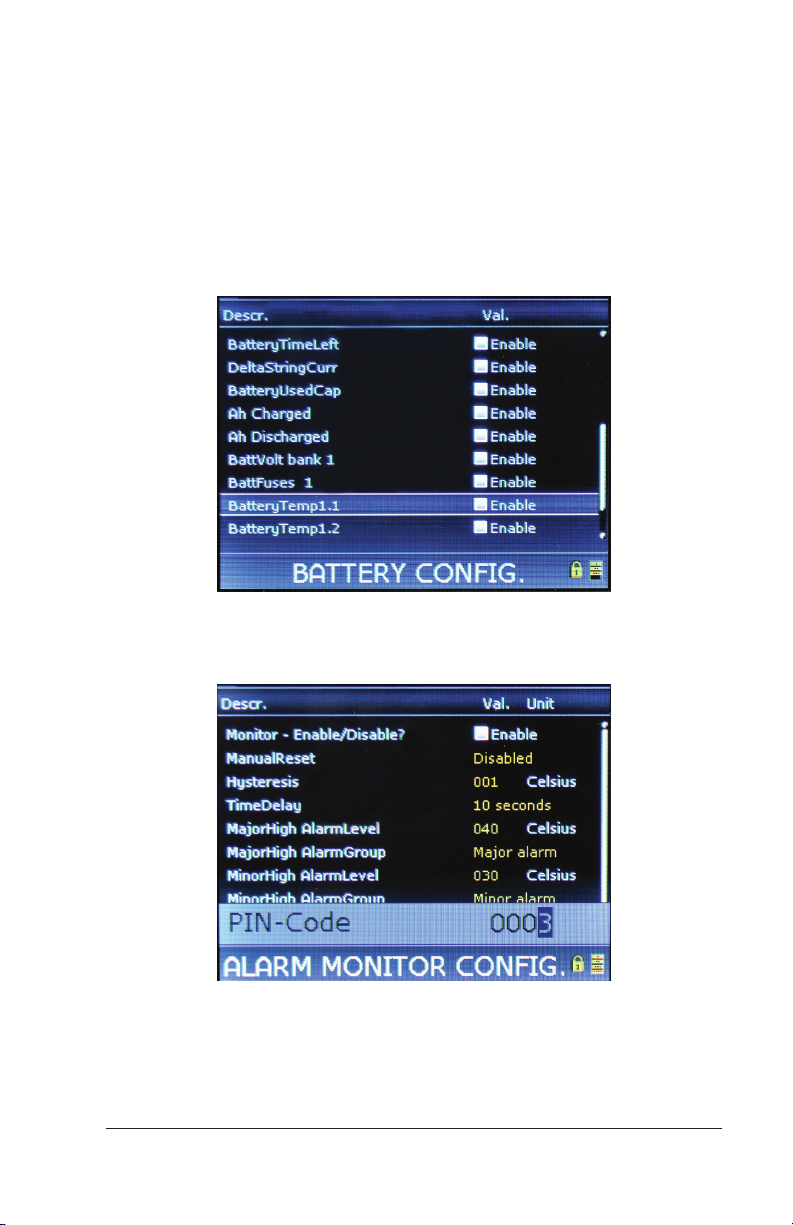
Enabling Battery Temperature Input through
theDisplay
To enable input:
1. From the Main menu, select Alarm Config.
2. Select Battery.
3. Scroll down to BatteryTemp 1.x (where “x” is the input number to
which the probe is connected), and select it by pressing [ENTER].
Figure 5 – Select BatteryTemp 1.x
4. Select Monitor – Enable/Disable? (Press [Enter]).
Figure 6 – Enabling Temperature Probe Monitor
5. Use UP and DOWN arrow keys to enter the PIN (default PIN is
0003). Press [ENTER] to accept. (Press and hold [ ENTER] for
Smartpack S.)
28 Configuration Guide: Eltek Controllers – Doc. No. 370013.063, Issue 1.4, May 2022
Page 29
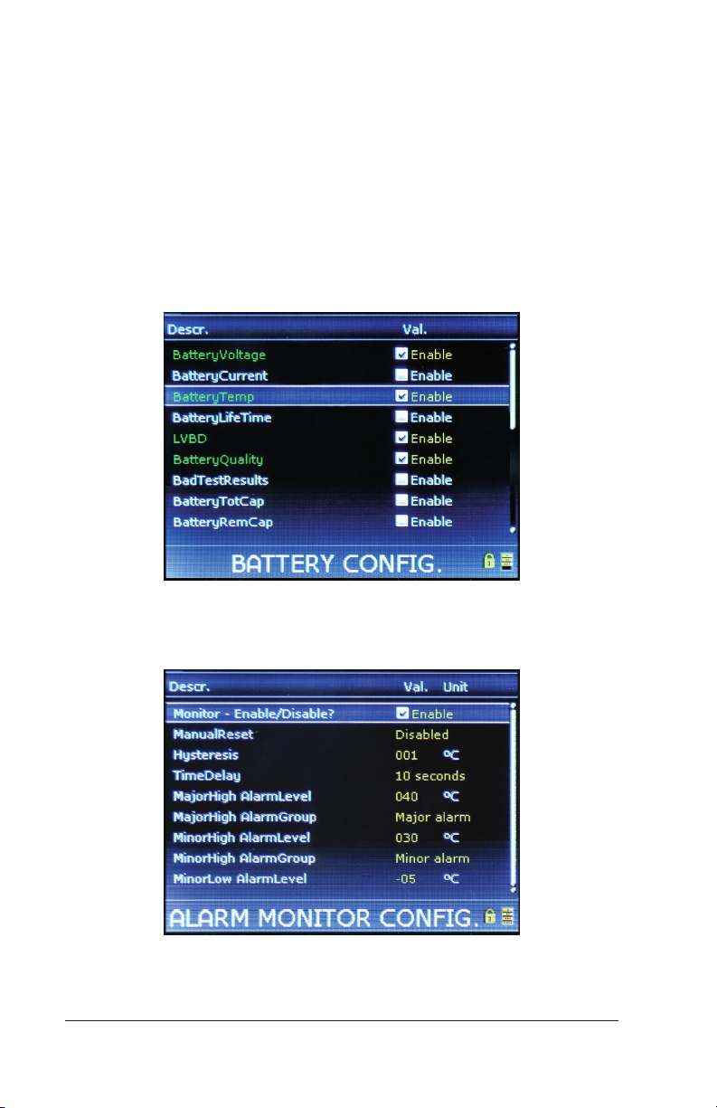
6. Push the Down arrow to Enable, and push the Enter button.
7. Scroll down to Alarm Levels to change alarm settings if desired.
Note: These alarm settings apply only to the specific input. If you
do not want an alarm only for this specific input, set the temperature values outside of the expected range, and finish remaining
steps for monitoring all probes.
8. Exit BatteryTemp 1.x, and return to the Battery section. Repeat
steps 3 – 6 for additional probes.
9. Select Battery Temp.
Figure 7 – Enabling Battery Temperature Monitor
10. Select Monitor – Enable/Disable? (Press [Enter]).
Figure 8 – Battery Temperature Monitor Enable
Configuration Guide: Eltek Controllers – Doc. No. 370013.063, Issue 1.4, May 2022 29
Page 30

11. Use UP and DOWN arrow keys to enter the PIN (default PIN is
0003). Press [ENTER] to accept. (Press and hold [ ENTER] for
Smartpack S.)
12. Push the Down arrow to Enable, and push the Enter button.
13. Scroll down to Alarm levels to adjust values to the desired
parameters.
14. Exit the Battery section.
Battery Temperature Compensation
CAUTION: Battery temperature compensation requires specifications
from the battery manufacturer. DO NOT proceed without having
the documented specifications on hand. If unavailable, contact
the battery manufacturer directly. Eltek does not provide battery
specifications.
Battery temperature compensation adjusts battery charging voltage
after a predefined temperature threshold has been exceeded. The
reference voltage and temperature slope are specifications provided
by the battery manufacturer. Maximum and minimum compensation
voltage should also be defined to protect load equipment.
A battery input must be enabled per instructions in "Enabling
Battery Temperature Input" on page 25, or using an external CAN
Node (such as the Battery Monitor or FlexiMonitor) before enabling
Temperature Compensation.
The fields available are:
• Temperature compensation – check the box to enable Tempera-
ture Compensated Charging parameters. Clicking again on the
box (uncheck) disables the parameters.
• Minimum compensation voltage – minimum charging voltage per
battery cell (protects connected load equipment).
• Maximum compensation voltage – maximum charging voltage
per battery cell (protects connected load equipment).
• Reference voltage – charging voltage per battery cell recom-
mended by the battery manufacturer at the reference temperature specified in the Reference temperature field.
• Reference temperature – the reference temperature in degrees
Celsius that the battery manufacturer specifies for the charging
voltage entered in the Reference voltage field.
30 Configuration Guide: Eltek Controllers – Doc. No. 370013.063, Issue 1.4, May 2022
Page 31
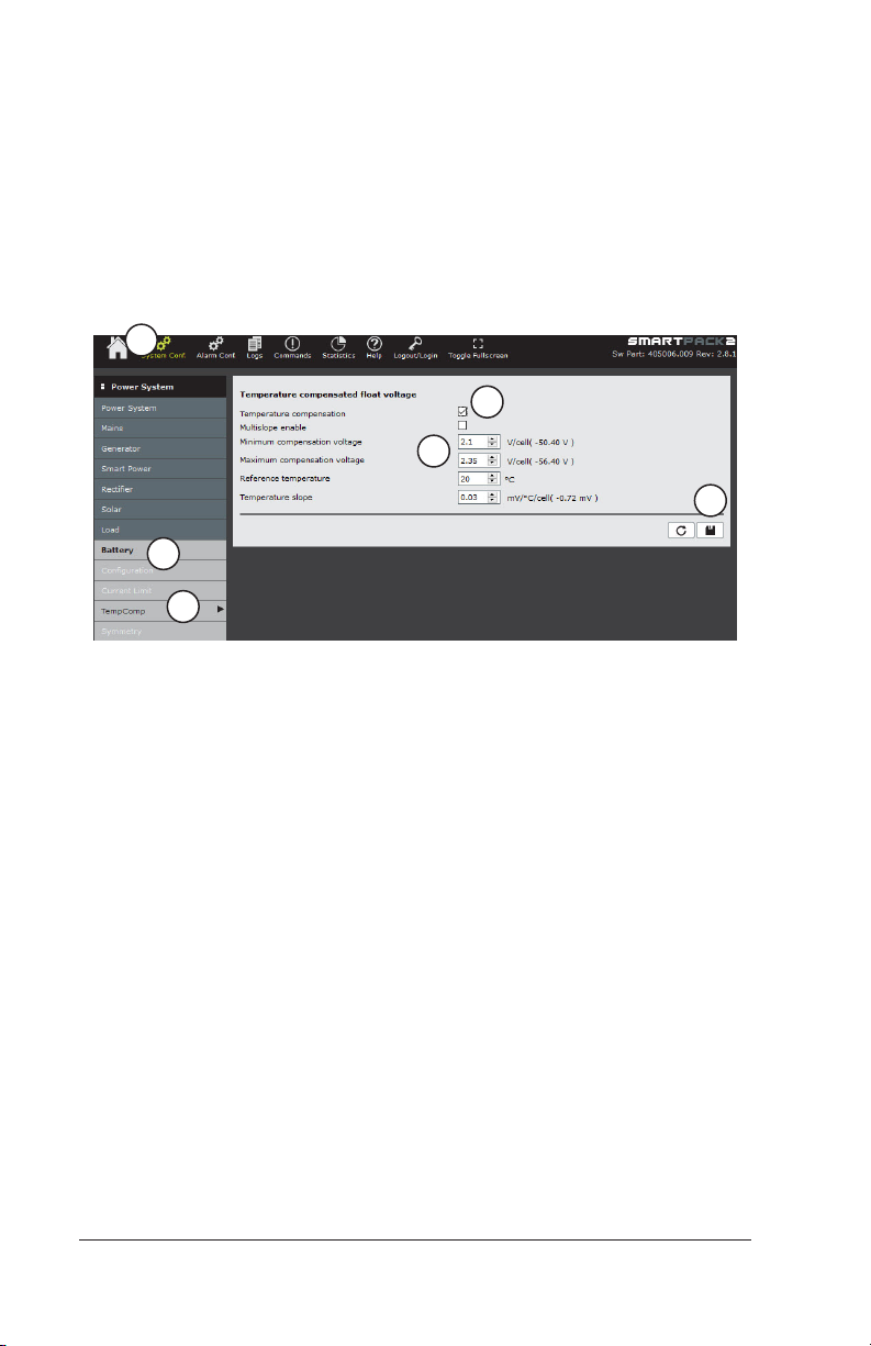
• Temperature slope – compensation factor in millivolts per
degree Celsius per battery cell recommended by the battery
manufacturer.
Setting Battery Temperature Compensation through
the Browser Interface
To set battery temperature compensation through the browser
interface:
1
4
5
6
2
3
Figure 9 – Setting Battery Temperature Compensation
Using the Browser Interface
1. Click on the System Conf. icon in the top menu bar.
2. In the left menu bar, click on Battery (below the Power System
heading).
3. Click on TempComp.
4. Enable feature by checking the box.
5. Enter settings as required for the batteries. See the descriptions
of the fields above.
6. Click on the Save button (“diskette”) to save changes.
Configuration Guide: Eltek Controllers – Doc. No. 370013.063, Issue 1.4, May 2022 31
Page 32
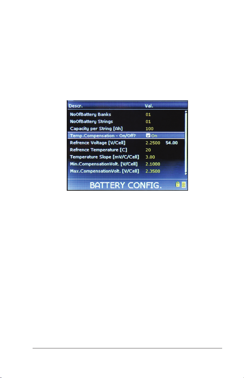
Setting Battery Temperature Compensation through
the Display Panel
To set battery temperature compensation through the display panel:
1. From the Main Menu, select Sys. Config.
2. Select Battery.
3. Select Battery Config. This selection displays the BATTERY
CONFIG. page.
Figure 10 – Battery Temperature Compensation Using the Display Panel
4. Use the down arrow key to scroll to Temp. Compensation – On/
O?
This line and the next five lines are for temperature compensation
(down through Max.CompensationVolt. [V/Cell])
5. To enable Temperature Compensation, select the box by pressing
the [ENTER] key, then use UP and DOWN arrow keys to enter the
PIN (default PIN is 0003). Press [ENTER] to accept. (Press and
hold [ ENTER] for Smartpack S.)
6. Use the UP or DOWN arrow keys to place a check mark in the box.
7. Press the [ENTER] key to save the change.
8. Adjust the other parameters as desired. Refer to the parameter
descriptions above (page 30) for details.
32 Configuration Guide: Eltek Controllers – Doc. No. 370013.063, Issue 1.4, May 2022
Page 33
7. Setting Battery Information
The controller has several features and alarms that need the
appropriate battery information to work properly. Features like
the capacity function of the generator feature, the battery meter
on the home page, and many alarms like BatteryTotCap and
BatteryUsedCap, etc., need to have the initial battery capacity
information entered during commission. In addition, the battery
discharge test works best when the battery tables are used.
Enabling Battery Information through the
Browser Interface
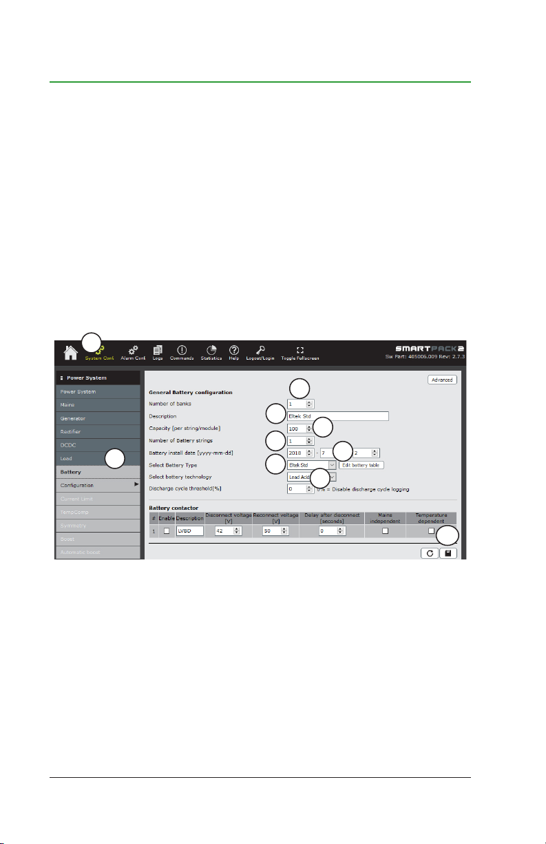
To enable battery information using the browser interface:
1
3
4
6
2
Figure 1 – Setting General Battery Configuration Using the Browser Interface
1. Click on System Config.
2. In the left menu bar, click on the Battery button.
3. On the parameters section of the page, leave the Number of
banks at one.
4. Enter a Description, if desired.
5. Enter the battery Capacity per string.
Configuration Guide: Eltek Controllers – Doc. No. 370013.063, Issue 1.4, May 2022 33
8
5
7
9
10
Page 34
6. Enter the Number of Battery strings.
7. Enter the Battery Install date.
8. Select your Battery Type (if available), using the drop-down list;
or, leave as Eltek Std, if using VRLA batteries, and you do not
have your own battery table. (For additional details, you may
consult the User Guide: Eltek Controller Web Interface, Doc. No.
370035.013.)
9. From the Select battery technology list, choose the technology
that applies to your batteries.
10. Click on the Save button (“diskette”) to save changes.
Enabling Battery Information through the
Display
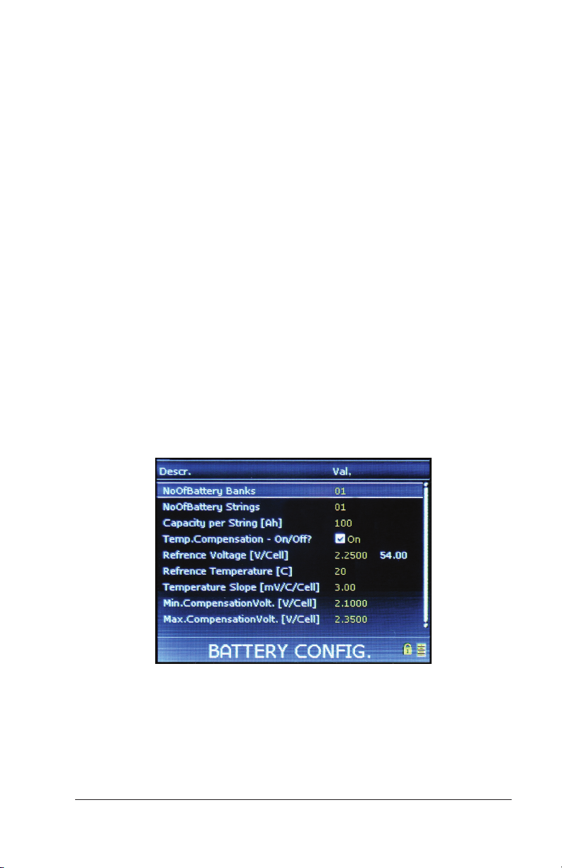
To enable battery information using the using the display panel:
1. From the Main Menu, select Sys Config.
2. Scroll down and choose Battery.
3. Scroll down to Battery Config and press [Enter].
Figure 2 – Battery Configuration Setup
4. Leave the NoOfBattery Banks at one (1).
5. Scroll down to NoOfBattery Strings and press [Enter].
34 Configuration Guide: Eltek Controllers – Doc. No. 370013.063, Issue 1.4, May 2022
Page 35
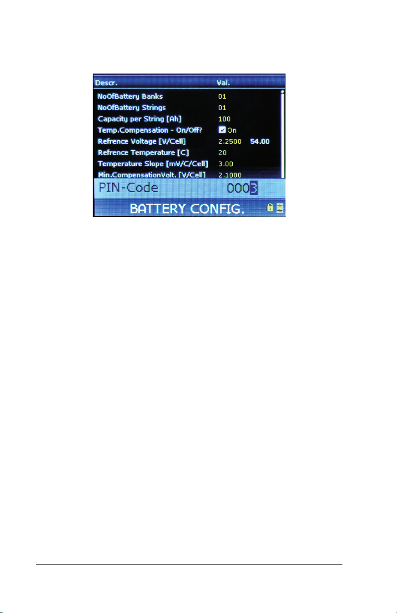
6. Use UP and DOWN arrow keys to enter the PIN (default PIN is
0003). Press [ENTER] to accept. (Press and hold [ ENTER] for
Smartpack S.)
Figure 3 – Battery Configuration PIN Entry
7. Change the value.
8. Scroll down to Capacity per String [Ah] and press [Enter].
9. Use UP and DOWN arrows to change the value.
Note: If you want to enter the battery install date, or change the
battery type, you must use the browser interface, as described in
the previous section.
10. Exit the Battery section.
Configuration Guide: Eltek Controllers – Doc. No. 370013.063, Issue 1.4, May 2022 35
Page 36
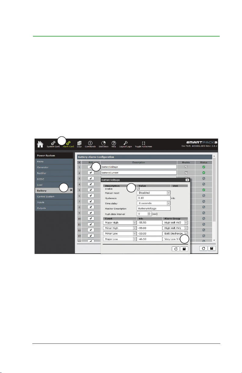
8. Setting Battery Voltage Alarm
Battery voltage alarm triggers an alarm when the battery voltage
gets too high or too low. The parameters should match the
recommendations of your battery manufacturer or company policy.
The battery voltage alarm can be adjusted from either the browser
interface or the display.
Setting Battery Voltage Alarm through the
Browser Interface
To set Battery Voltage alarm parameters through the browser
interface:
1
3
2
Figure 1 – Battery Voltage Alarm Configuration
1. Click on the Alarm Conf. icon in the top menu bar.
2. In the left menu bar, click on the Battery and wait for the list to
populate.
3. Under the Battery Alarm Configuration bar, find BatteryVolt-
age and click on the Edit button (gear symbol). The edit window
opens.
4
5
36 Configuration Guide: Eltek Controllers – Doc. No. 370013.063, Issue 1.4, May 2022
Page 37
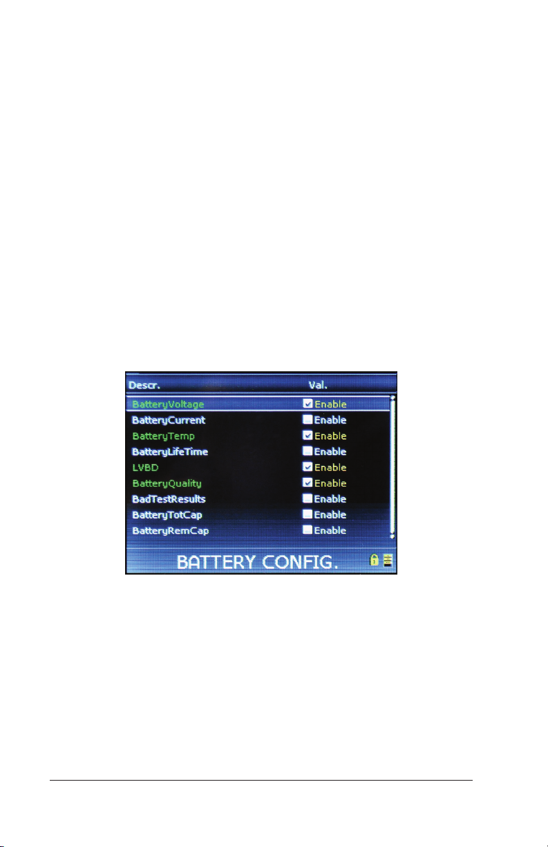
4. Locate the Alarm Monitor line and check the Enable box.
NOTE: The edit window may vary from revision to revision. Some
edit windows have a General tab and a Calibration tab; if so, click
on the General tab.
5. Configure parameters as desired. Click the Save button (diskette
symbol) to save changes.
Setting Alarm Battery Voltage Alarm through
the Display Panel
To set alarm Battery Voltage alarm parameters through the display
panel:
1. From the Main Menu, select AlarmConfig.
2. Select Battery.
3. Select BatteryVoltage, and then press the [ENTER] key.
Figure 2 – Enabling Battery Voltage
4. Select Monitor – Enable/Disable?
Configuration Guide: Eltek Controllers – Doc. No. 370013.063, Issue 1.4, May 2022 37
Page 38
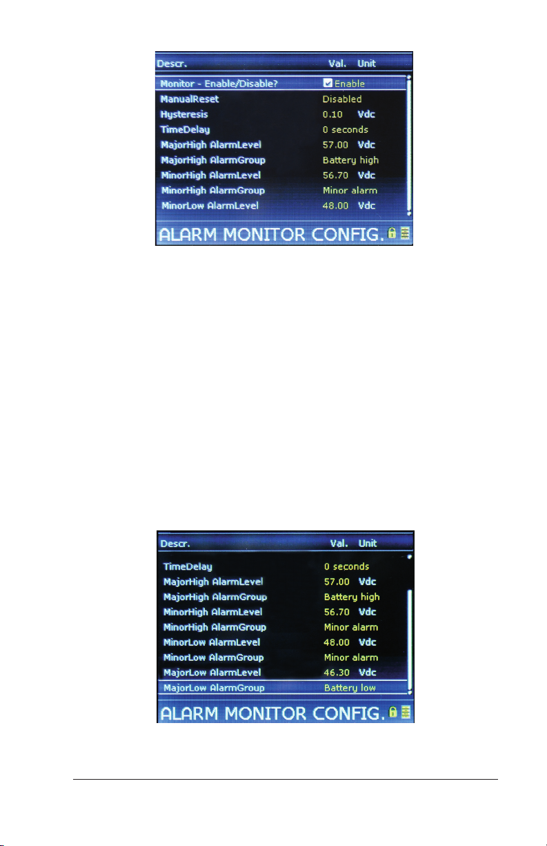
Figure 3 – Enabling Battery Voltage Alarm
5. Use UP and DOWN arrow keys to enter the PIN (default PIN is
0003). Press [ENTER] to accept. (Press and hold [ ENTER] for
Smartpack S.)
6. Use either the UP or DOWN arrow key to place a check mark in the
box.
7. Press the [ENTER] key to save the change.
8. At the bottom of the page is where alarm thresholds are set. For
Battery Voltage there are four events: Major High, Minor High,
Minor Low, and Major Low. Each event has an Alarm Level setting
(voltage setting) and Alarm Group setting (for output relay assignment). Use the [ENTER] key to select an event parameter to
change. Use the UP and DOWN arrow keys to adjust the settings.
Press the [ENTER] key to save.
Setting Alarm Group Assignments
9. Exit the Battery section.
38 Configuration Guide: Eltek Controllers – Doc. No. 370013.063, Issue 1.4, May 2022
Page 39
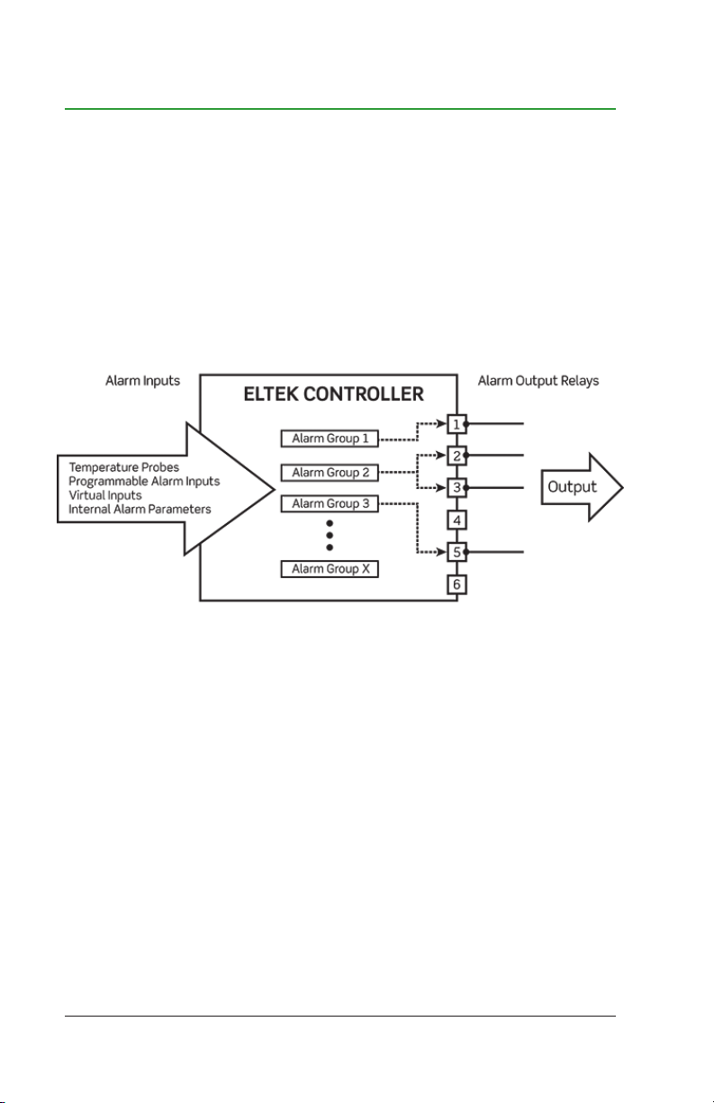
9. Configuring Output Relay
Alarm settings are configured in the Alarm Configuration section of
both the browser interface and display menus. Alarms are assigned
to alarm groups. Alarm groups, in turn, are assigned to output relays.
These assignments are user-configurable.
As the following diagram illustrates, this section explains how to set
up alarm inputs (Internal Alarm Parameters in this example), how
to assign the parameters to alarm groups, and how to assign alarm
groups to output relays.
Figure 1 – Alarm Groups to Output Relays
NOTE: Each controller has dierent output interfaces:
• The Smartpack2 Touch controller does not have any output relays
built in; instead, an Eltek I/O Monitor is required. I/O Monitors
feature six output relays.
• The Smartpack2 controller does not have any output relays built
in; instead, an Eltek I/O Monitor is required. I/O Monitors feature
six output relays.
• The Compack controller has three output relays; they are located
on the top of the controller.
• The Smartpack S controller has six output relays; they are located
on the left side of the controller (when viewed from the front).
Configuration Guide: Eltek Controllers – Doc. No. 370013.063, Issue 1.4, May 2022 39
Page 40
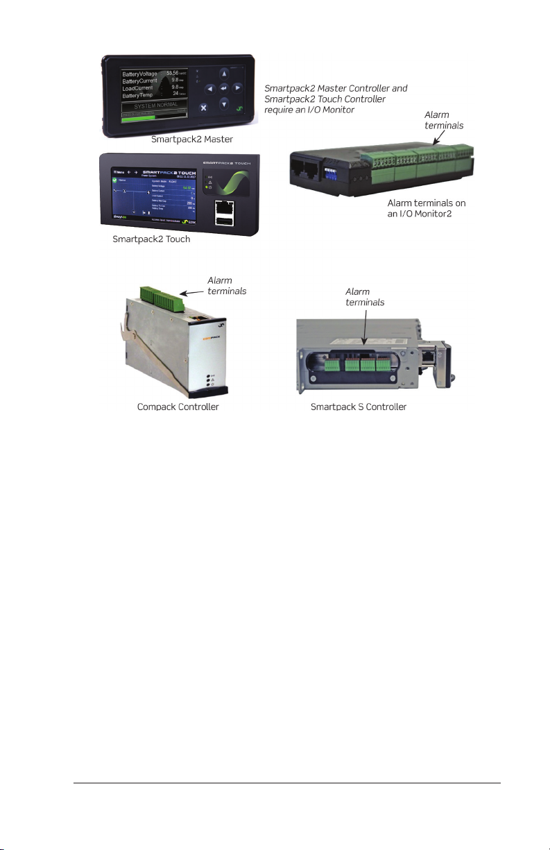
Figure 2 – Configurable Inputs
Note: To make alarm connections to the Smartpack R controller,
check the installation manual for your system. Connections to the
Smartpack R are not made directly to the controller, but to the
interface on the power system.
Output Alarm Relays
Output alarm relays are form-C contacts that are triggered if mapped
to one or more alarm groups.
40 Configuration Guide: Eltek Controllers – Doc. No. 370013.063, Issue 1.4, May 2022
Page 41
Setting Output Relays through the Browser
Interface
Note: Each controller has dierent functionalites and, therefore
present those options in the columns that are displayed at the top of
the screen. The following screenshots are representative of dierent
controllers.
Only configure alarm relay outputs, leaving default settings for the
Battery Contact and Load Contact on the Smartpack S, Compack
and Smartpack R controllers.
Additionally, do not rename the first seven (7) alarm groups, as this
will not change functionality, but could cause confusion. For example,
renaming Mains Alarm to High Voltage Alarm does not change the
function of that alarm group, but instead will display the name High
Voltage Alarm during an AC failure; it still monitors the Mains Alarm.
To set output relays through the browser interface:
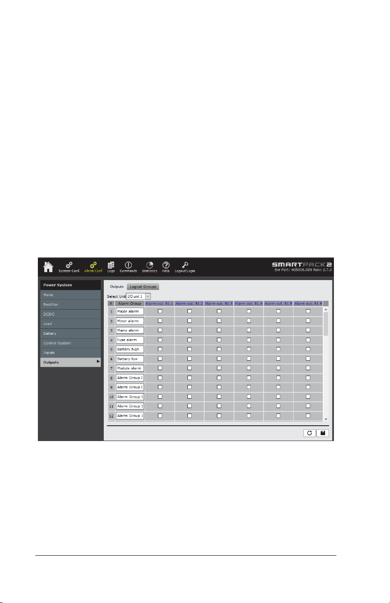
Figure 3 – Alarm Outputs Page (Smartpack2 Controller)
Configuration Guide: Eltek Controllers – Doc. No. 370013.063, Issue 1.4, May 2022 41
Page 42
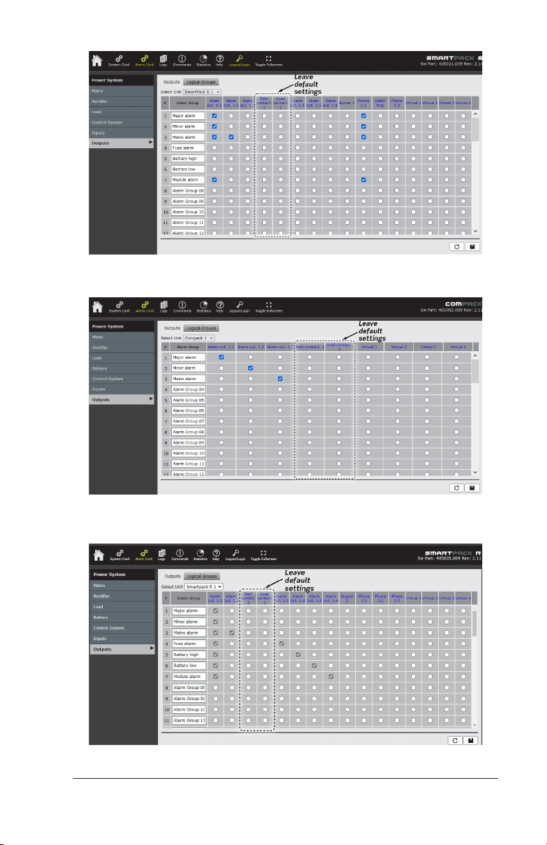
Figure 4 – Alarm Outputs Page (Smartpack S Controller)
Figure 5 – Alarm Outputs Page (Compack Controller)
Figure 6 – Alarm Outputs Page (Smartpack R Controller)
42 Configuration Guide: Eltek Controllers – Doc. No. 370013.063, Issue 1.4, May 2022
Page 43

1. Click on the Alarm Conf. icon in the top menu bar.
2. In the left menu bar, click on Outputs and wait for the list to
populate.
NOTE: At the top of the window is a drop-down list called Select
Unit. Use this to select the control unit to which the alarms are
connected. This is particularly important for the Smartpack2 Master controller, since the unit itself only has an audible buzzer to
assign to the alarm groups. For the Smartpack2 controller, I/O
Monitors are required for external alarm input and output; the appropriate I/O Monitor must be selected in the drop-down menu in
order to modify alarm relay assignments.
3. For each alarm group that should trigger an output relay, place
a check in the box under the relay(s) desired. Relays can be
assigned to multiple alarm groups, and alarm groups can trigger
multiple relays.
4. Change alarm group names as desired to reflect the alarm to be
indicated by that group. Click in the Alarm Group field to edit the
name.
5. Click the Save button (the diskette symbol) to save changes.
Setting Output Relays through the Display
Panel
To set output relays through the display panel:
1. From the Main Menu, select AlarmConfig.
2. Use DOWN arrow to find Outputs and press [ENTER] to select
Outputs. Wait for the page to populate, which can take about a
minute to complete.
Configuration Guide: Eltek Controllers – Doc. No. 370013.063, Issue 1.4, May 2022 43
Page 44
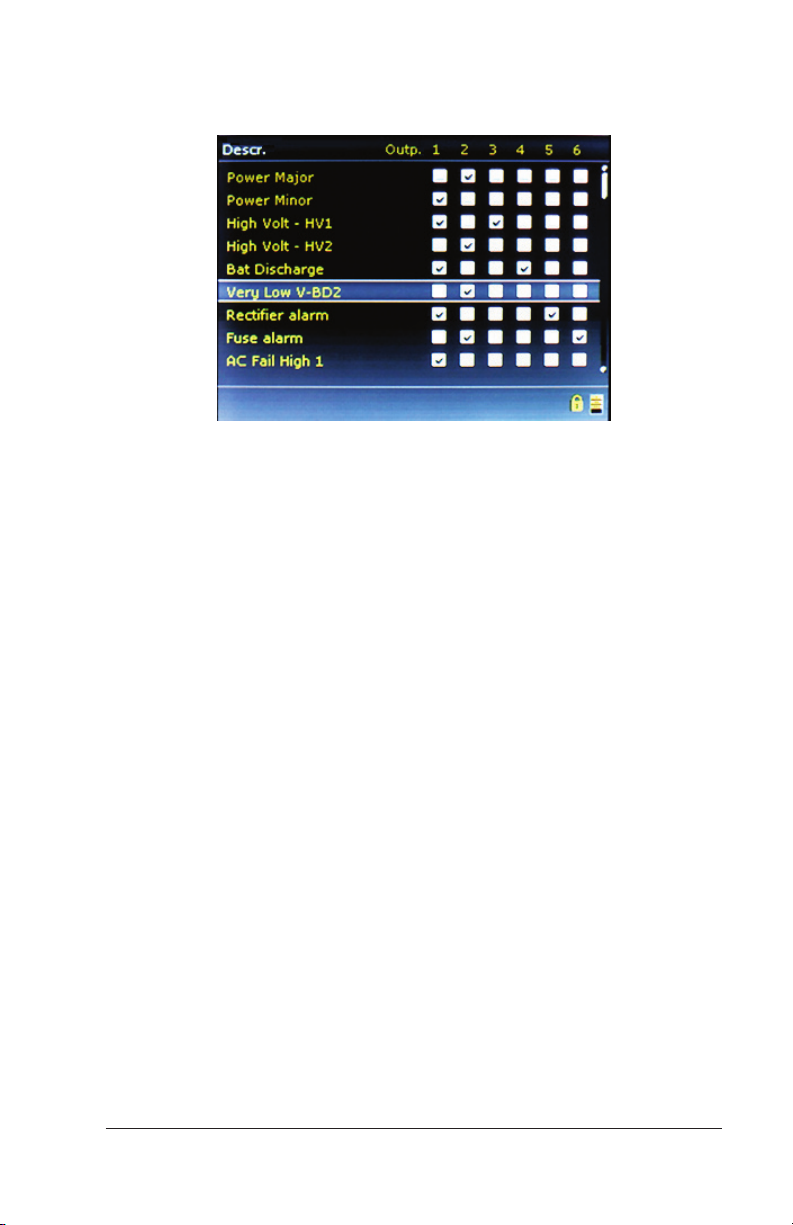
NOTE: All available alarm relays from all controllers and monitors
in the system are listed on this page.
Figure 7 – Setting Output Relays Using the Display Panel
3. Use the Right Arrow to jump through multiple screens to access
the I/O Monitor Outputs in the Smartpack2. Press the [ENTER]
key to select an alarm group.
4. Use UP and DOWN arrow keys to enter the PIN (default PIN is
0003). Press [ENTER] to accept. (Press and hold [ ENTER] for
Smartpack S.)
5. Use the RIGHT and LEFT arrow keys to point to the output relay
that the alarm group should trigger. Use the UP and DOWN arrow
keys to place a check mark in the box. Press [ENTER] to save the
change.
More than one relay can be selected. Note that there are six
output alarm relays for the Smartpack2 controller (using the I/O
Monitor2 device).
Output alarm relays are set. Use the same process for other alarm
groups as needed.
44 Configuration Guide: Eltek Controllers – Doc. No. 370013.063, Issue 1.4, May 2022
Page 45
10. Alarm Relay Test
The alarm relays can be tested manually through both the browser
interface and display.
CAUTION: Testing alarm relays causes alarm conditions.
Make sure monitoring equipment and personnel are aware of
such testing and will not be adversely aected. It is not
recommended to test alarm relays from an o-site location!
CAUTION: Some controller units list low-voltage disconnect
(LVD) contactors. Activating these contactors will open
them and disconnect any batteries or loads connected!
Testing Output Relays through the Browser
Interface
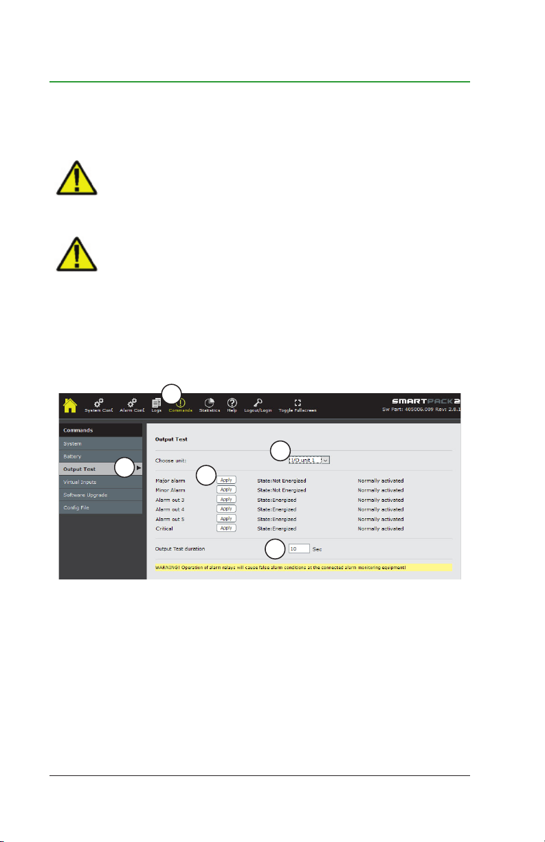
To test output relays through the browser interface:
1
4
2
5
3
Figure 1 – Testing Output Relays Using the Web Interface
1. Click on the Commands icon in the top menu bar.
2. In the left menu bar, click on Output Test.
3. All output relays for the unit indicated in the Output Test box are
displayed. The duration of the test can be set by changing the
number of seconds in the Output Test duration box.
Configuration Guide: Eltek Controllers – Doc. No. 370013.063, Issue 1.4, May 2022 45
Page 46
NOTE: The Output Test duration setting is only available in the
browser interface or the Smartpack2 Touch screen.
4. Use the Output Test drop-down menu to select the control unit
to which the alarms are connected. This is particularly important
for the Smartpack2 Master controller, since the unit itself does
not have any output relays. For the Smartpack2 controller, I/O
Monitors are required for external alarm output; the appropriate
I/O Monitor must be selected in the drop-down menu in order to
test alarm output.
5. Click the Apply button to change the state of the relay. The state
change lasts for as long as specified in the Output Test duration
box.
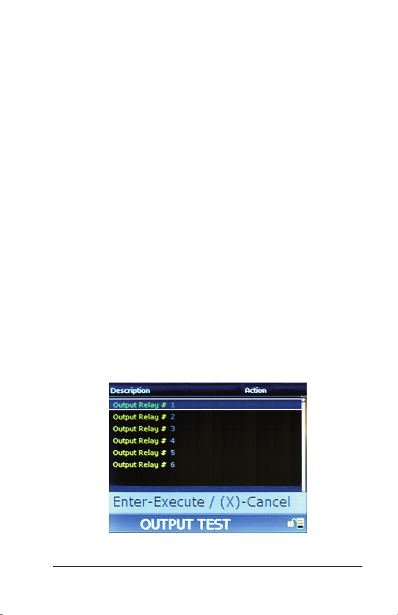
Testing Output Relays through the Display
Panel
To test output relays through the display panel:
1. From the Main Menu, select Commands.
2. Select Output Test.
3. All output relays for the unit indicated in the Output Test box are
displayed.
NOTE: The Output Test duration setting is only available in the
browser interface or the Smartpack2 Touch screen. The duration
is 10 seconds by default
Figure 2 – Testing Output Relays Using Display Panel
46 Configuration Guide: Eltek Controllers – Doc. No. 370013.063, Issue 1.4, May 2022
Page 47

4. Select an output relay to test.
5. Use UP and DOWN arrow keys to enter the PIN (default PIN is
0003). Press [ENTER] to accept. (Press and hold [ ENTER] for
Smartpack S.)
6. Press the [ENTER] key to execute the test, or select the [X] key
to cancel.
7. Repeat for additional relays.
Alarm relay test is complete.
Configuration Guide: Eltek Controllers – Doc. No. 370013.063, Issue 1.4, May 2022 47
Page 48

11. Setting Site Information
NOTE: Site information can be set only through the browser interface
or the Smartpack2 Touch controller, not through the display.
However, site information is readable through the display at the
following path:
Main Menu > Logs/Reports > Inventory Report
In the browser interface, site information is set on the System Info
page, where details about the site and the power system installation
are entered. Entering a field value is optional, but it is highly
recommended for future identification, maintenance and traceability.
The following fields are available (refer to Figure 1).
• Company – Name of the company that owns the power system
• Site – Name and/or ID of the site
• Model – Power system model (refer to documentation provided
with the system)
• Serial Number – System serial number or other identification
number
• Install Date – Installation date (year, month, day)
• Service Date – Date of latest service (year, month, day)
• Responsible – Person or company that serviced the power system
• Message lines (1 and 2) – Free-form fields for any messages re-
lated to services performed on the power system (results, unresolved issues, etc.)
• Latitude – Latitude of the site (degrees, hours, minutes, hemi-
sphere [north or south])
• Longitude – Longitude of the site (degrees, hours, minutes, direc-
tion [east or west])
• Elevation – Site elevation (in meters)
48 Configuration Guide: Eltek Controllers – Doc. No. 370013.063, Issue 1.4, May 2022
Page 49
To Set Site Information through the Browser
Interface
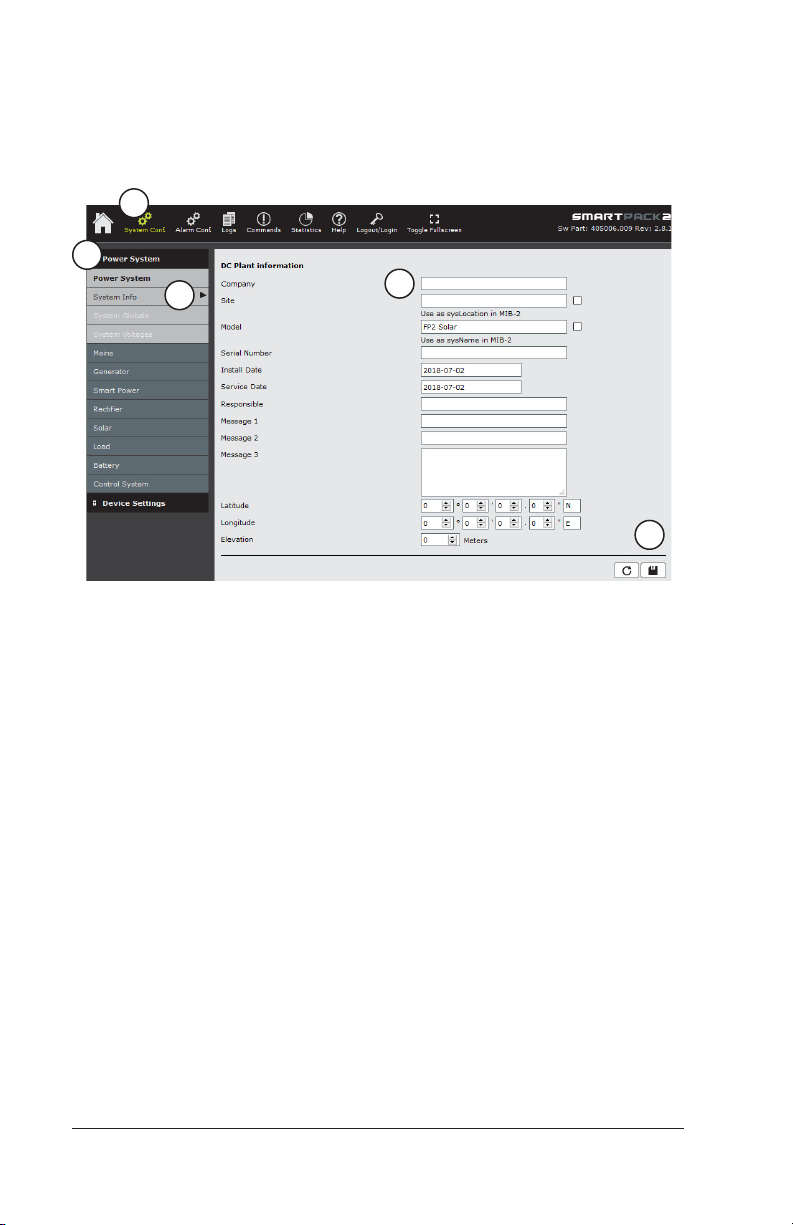
To set site information through the browser interface:
1
2
3
Figure 1 – System Information Page
1. Click on the System Conf. icon in the top menu bar.
4
5
2. In the left menu bar, click on Power System.
3. Click on System Info.
4. Fill in the fields as desired. All fields are optional.
5. Click on the save icon (diskette) to save changes.
Configuration Guide: Eltek Controllers – Doc. No. 370013.063, Issue 1.4, May 2022 49
Page 50

12. Configuration Backup
Configuration backup is an important part of system configuration.
The configuration file allows you to restore your system to a previous
state after a replacement unit is installed, or if unauthorized or
undesirable changes have been made.
Eltek programs the controller from the factory with a default
configuration, but any changes made in the field need to be saved.
Eltek has provided two ways to accomplish this task, but each
method has its own limitations.
Overview
The following sections provide a description of the dierent methods.
• Full Backup
• Save Change Log to XML (ver. 2.5 or later)
Note: Backups do not retain the IP address settings and SNMP
configuration.
Full Backup
A full backup downloads a complete “snapshot” of the controller
settings and can be used to program a controller that has been reset
to factory defaults. This method gives you a file with an extension of
.HEX for every piece of the controller (for example, Master controller,
Basic controller, and all CAN devices).
These files can be uploaded individually via the front display or
via the browser interface and will restore the controller to the
configuration when the file was saved.
Note: These files are good only for the controller and software
revision for which it was saved. This means that these backup files
should not be used on replacement controllers, and need to be
redownloaded after any software upgrade.
50 Configuration Guide: Eltek Controllers – Doc. No. 370013.063, Issue 1.4, May 2022
Page 51

Save Change Log to XML (ver. 2.5 or later)
This method downloads an XML file based on changes recorded
in the controller’s change log. This file can be used to configure
a controller after a replacement has been installed, or configure
multiple controllers in similar systems.
This method is very quick, and gives you a single file, with an
extension of .XML (Changelog.XML) for all controller pieces (Master,
Touch, Basic, Basic Industrial, Smartpack S, SmartpackR, or Compack,
and CAN Nodes).
This file can be used for replacement controllers, even if the software
has been updated since the file was generated. You must use the
browser interface to generate this file.
Procedures
Note: Backup files are valid only for the system and software version
used to create the backup. Never use the backup on another system
or dierent software version.
The following sections describe dierent backup procedures
applicable to various controllers.
• Smartpack2 Master controller – Use the display to save a HEX file
to the controller SD card; or use the browser interface to save a
HEX or an XML file to a computer.
• Smartpack2 Touch controller – Use the browser interface to save
a HEX or an XML file to a computer.
• Smartpack S controller – Use the display to save a HEX file to
the controller's internal memory; or use the browser interface to
save a HEX or an XML file to a computer. (To retrieve a copy of a
backup file on the controller's internal memory, you must use an
FTP client to copy the file to a computer.)
• Smartpack R controller – Use the browser interface to save a HEX
or an XML file to a computer.
• Compack controller – Use the browser interface to save a HEX or
an XML file to a computer.
Configuration Guide: Eltek Controllers – Doc. No. 370013.063, Issue 1.4, May 2022 51
Page 52
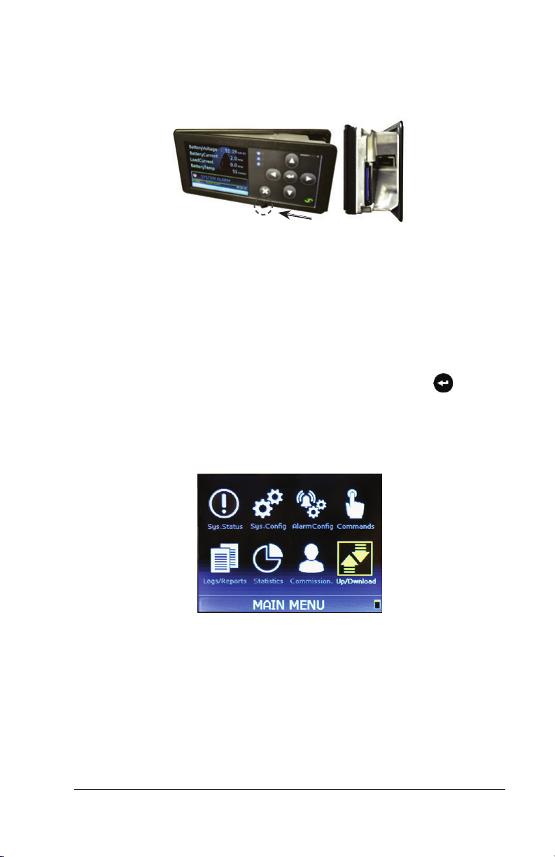
Before making a backup with a Smartpack 2 Master, verify that an
SD card is present, and properly inserted in the SD card slot. Slide
the lever on the front of the controller from right to left, in order to
access the SD card slot.
Figure 1 – Smartpack2 Master Controller Display and SD card slot
Making a Full Backup through the Display
(Smartpack2 Master, Smartpack S)
To backup your system configuration using the display:
1. On the display, push the Up and Down Arrows + Enter to
unlock.
2. From the Main Menu, using the navigation keys on the display,
navigate to the icon on the screen labeled Up/Download, and
then press the Enter key.
Figure 2 – Smartpack2 Master main menu icons
52 Configuration Guide: Eltek Controllers – Doc. No. 370013.063, Issue 1.4, May 2022
Page 53
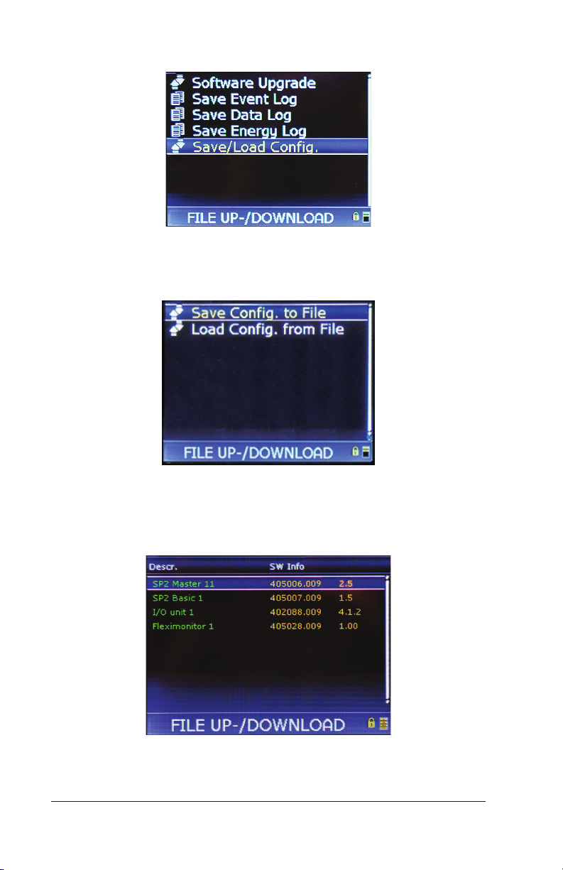
3. Choose Save/Load Config, and press Enter.
Figure 3 – Save/Load Config
4. Choose Save Config. to file, and press Enter.
Figure 4 – Saving Config File
5. On the new screen, choose SP2 Master 11 (Smartpack S_1), and
press Enter.
Figure 5 – Choosing Master Controller
Configuration Guide: Eltek Controllers – Doc. No. 370013.063, Issue 1.4, May 2022 53
Page 54
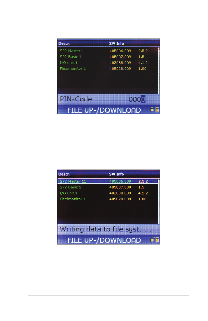
6. At the prompt, navigate with the Arrow Up key. Use UP and
DOWN arrow keys to enter the PIN (default PIN is 0003). Press
[ENTER] to accept. (Press and hold [ ENTER] for Smartpack S.)
Figure 6 – Smartpack2 Master PIN code prompt
7. Observe that the lock pad on the lower right corner on the screen
shows it in the open position; then press Enter again.
The message “Writing data to file system” appears on the lower
screen to indicate that the configuration is being saved. The
process will take several minutes.
Figure 7 – Smartpack2 Master “Writing data” message
54 Configuration Guide: Eltek Controllers – Doc. No. 370013.063, Issue 1.4, May 2022
Page 55
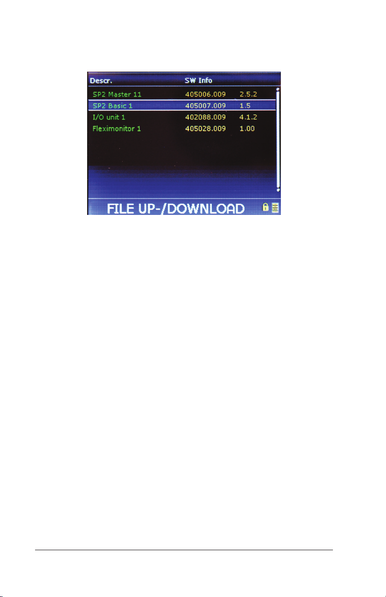
8. Continue to choose, one-by-one, the next control units listed on
the screen and repeat the previous steps, until the configuration
for the last item in the list has been saved.
Figure 8 – Choosing additional control units
Note: Files are saved in a folder named CONFIG on the SD card or
controller memory.
This concludes the procedure for making a backup of the system
configuration before an upgrade.
Configuration Guide: Eltek Controllers – Doc. No. 370013.063, Issue 1.4, May 2022 55
Page 56
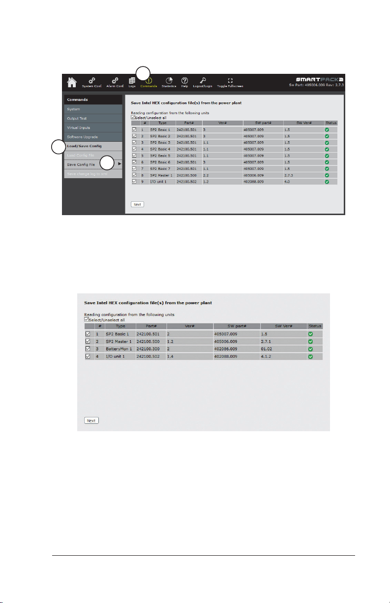
Making a Full Backup through the Browser Interface
To make a full backup using the browser interface:
1
2
3
Figure 9 – Saving a Configuration File
1. From the home screen, click on Commands >Load/Save Config. >
Save Config. File.
2. Select (check) all the items for backup.
Figure 10 – Select Items for Backup
3. After selecting the controller modules, click Next.
4. Click Start reading files.
56 Configuration Guide: Eltek Controllers – Doc. No. 370013.063, Issue 1.4, May 2022
Page 57
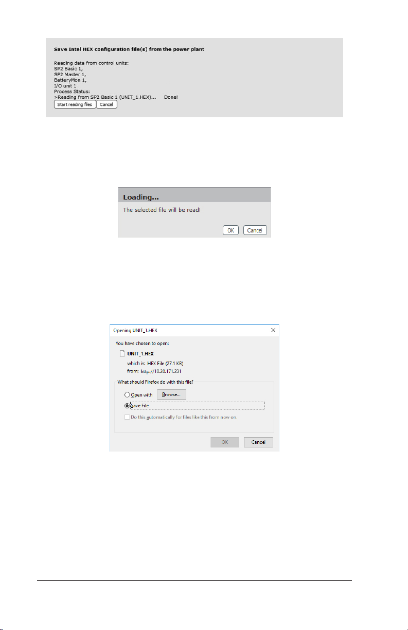
Figure 11 – Start Reading Files
5. A message appears: “Loading...The selected file will be read!” Click
OK on this dialog box.
Figure 12 – File Loading Message
6. A progress bar appears, indicating that the file is being generated.
After the file is generated, you will see another dialog, giving you
the option to open or save the generated file. Choose the option
for Save File, then click OK.
Figure 13 – Save File Dialog
7. After you save a configuration file, the screen returns to the
previous page and you are given options, based upon your original
Configuration Guide: Eltek Controllers – Doc. No. 370013.063, Issue 1.4, May 2022 57
Page 58
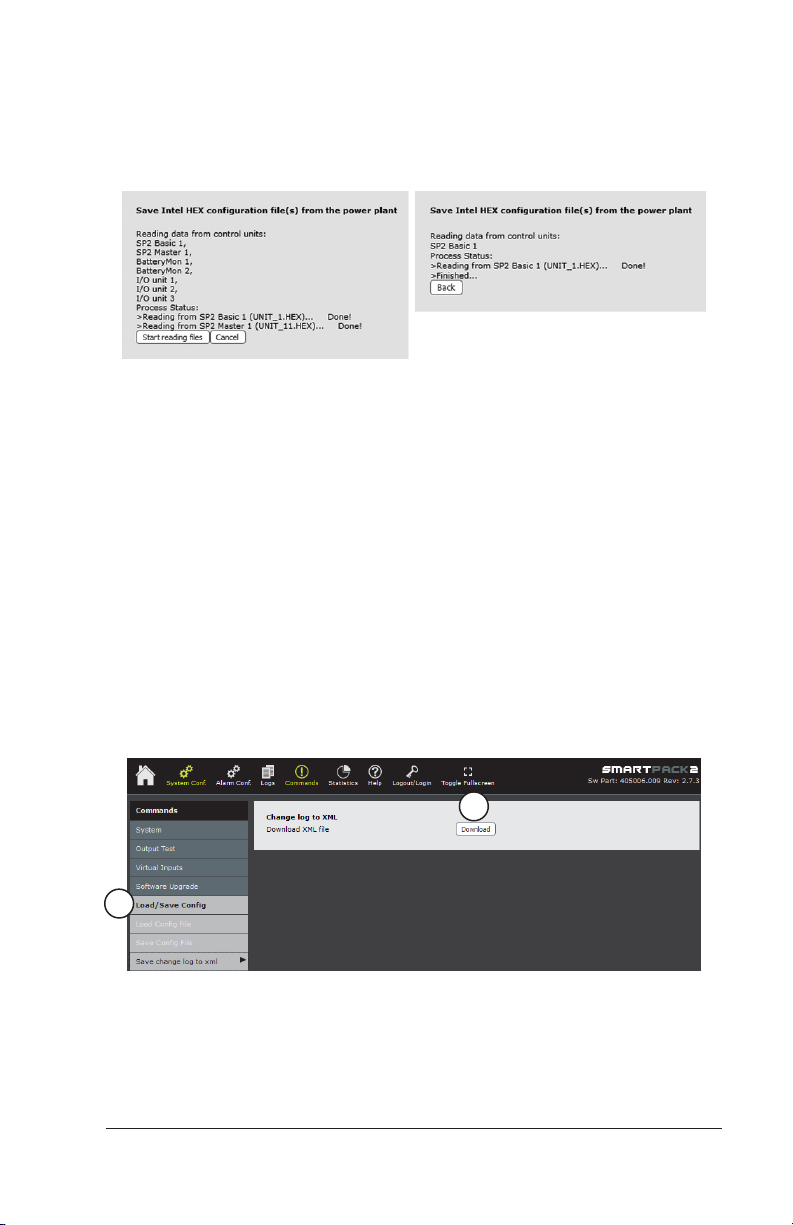
choice(s) of which file(s) to save. If all of your selected files
(Figure 10) have been saved, click the Back button. If you
previously selected multiple configuration files, and there are any
files remaining, click the Start reading files button again, to begin
saving the next file. Click Back after the last file has been saved.
Figure 14 – Options After Saving Files
After you click the Back button, the screen returns to the Save Intel HEX configuration file(s) page (Figure 10). From there you can
quit or navigate to other portions of the web browser interface.
8. Locate the backup files in the Downloads folder in the Windows
operating system. Copy the files to an archive where they can be
easily retrieved if needed.
Making an XML Backup from the Change Log
(BrowserInterface)
To make a backup from the change log (requires version 2.5 or later):
1. Click Commands > Load/Save Config > Save change log to XML.
2
1
Figure 15 – XML Backup from Changelog
2. Click the Download button.
58 Configuration Guide: Eltek Controllers – Doc. No. 370013.063, Issue 1.4, May 2022
Page 59
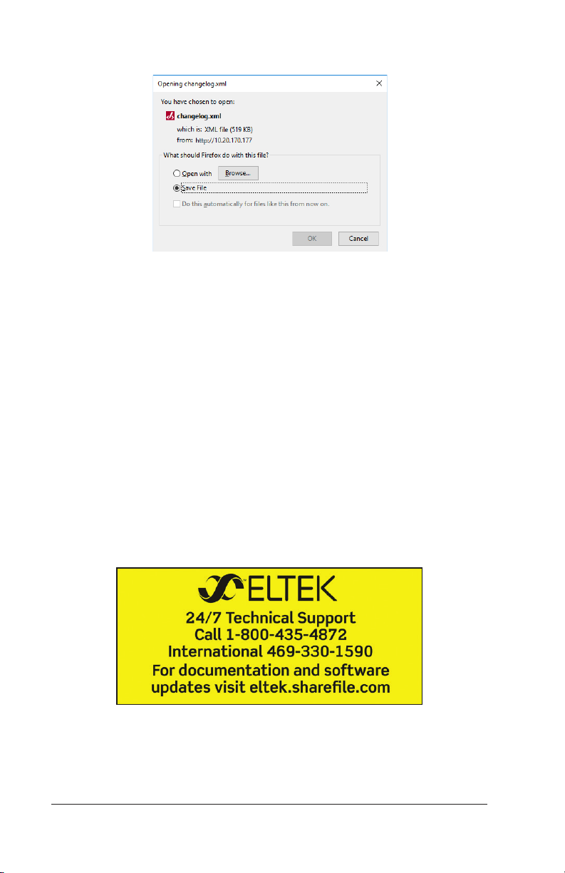
3. Click Save File and then OK.
Figure 16 – Save File Dialog
4. Find the file in the Downloads folder; it will be called
changelog.xml. Rename the file with a distinctive name to
identify it with your system. Archive the file in a place where it
can be easily retrieved if needed.
For assistance with technical questions and solutions,
please contact Technical Support by email at
or by phone at 1-800-435-4872.
Ordering information:
(469) 330-9100
Configuration Guide: Eltek Controllers – Doc. No. 370013.063, Issue 1.4, May 2022 59
Page 60

US Oce:
Eltek, Inc.
2925 E. Plano Parkway
Plano, Texas 75074, USA
Phone: +1 (469) 330-9100
Fax: +1 (972) 424-5050
www.eltek.com
Doc. No. 2061604
Published 05/06/22
International:
Gråterudv. 8, Pb 2340 Strømsø,
3003 Drammen, Norway
Phone: +47 32 20 32 00
Fax: +47 32 20 32 10
Eltek AS
 Loading...