

Page 1
®
Hardware Manual
Revision 2C
Page 2
Revision History
Revision Changes Date
1A First Edition 26.06.01 PP
2A Hardware Revision 2A 12.09.01 PP
2B Hardware Revision 2A 05.11.01 PP
2C Hardware Revision 2A 24.01.02 PP
DISCLAIMER!
The information in this document has been carefully checked and is believed
to be entirely reliable. However, no responsibility is assumed for inaccuracies.
ELTEC reserves the right to make changes to any products to improve
reliability, function or design. ELTEC does not assume any liability arising out
of the application or use of any product or circuit described in this manual;
neither does it convey any license under its patent rights nor the rights of
others. ELTEC products are not authorized for use as components in life
support devices or systems intended for surgical implant into the body or
intended to support or sustain life. Buyer agrees to notify ELTEC of any such
intended end use whereupon ELTEC shall determine availability and suitability
of its product or products for the use intended.
ELTEC points out that there is no legal obligation to document internal
relationships between any functional modules, realized in either hardware or
software, of a delivered entity.
This document contains copyrighted information. All rights including those of
translation, reprint, broadcasting, photomechanical or similar reproduction and
storage or processing in computer systems, in whole or in part, are reserved.
Other product and company names herein may be the trademarks of their
respective owners.
© 2002 ELTEC Elektronik AG, Mainz
Page 3

User's Manual Table of Contents
Table of Contents
1 Introduction............................................................................ 1—1
1.1 Technical Highlights................................................................ 1—1
1.2 Technical Details .................................................................... 1—4
1.2.1 Video Input...........................................................................1—5
1.2.2 Sync Input ............................................................................ 1—5
1.2.3 Clock Input ........................................................................... 1—5
1.2.4 Trigger Input ........................................................................ 1—6
1.2.5 Sync / Camera Control Output ............................................1—7
1.2.6 Power Supply out................................................................. 1—7
1.2.7 Data Transfer ....................................................................... 1—8
1.2.8 Packing Modes ....................................................................1—9
2 Hardware Installation ............................................................2—1
2.1 Installation Procedure: ............................................................ 2—1
2.2 Cable ......................................................................................2—2
2.3 Trouble Shooting - if it does not work ..................................... 2—3
2.4 Connectors .............................................................................2—4
2.4.1 Jumpers and Connectors Placement ..................................2—4
2.4.2 Connector X100................................................................... 2—5
2.4.3 Connector X101................................................................... 2—6
2.4.4 Connector Hirose X102 .......................................................2—8
2.4.5 Connector Hirose X103 .......................................................2—9
2.4.6 Connector Hirose X104 .....................................................2—10
2.4.7 Connector Hirose X105 .....................................................2—11
2.4.8 Connector 10-Pin Header X106 ........................................2—12
2.4.9 Connector X700................................................................. 2—12
2.5 Switches ...............................................................................2—12
2.6 Jumpers ................................................................................ 2—13
2.6.1 Jumper J104 ...................................................................... 2—13
PC_EYE®2+
I
Page 4

Table of Contents User's Manual
2.6.2 Jumper J100 ...................................................................... 2—14
2.6.3 Jumper J101 ...................................................................... 2—14
2.6.4 Jumper J102 ...................................................................... 2—15
2.6.5 Jumper J103 ...................................................................... 2—15
2.7 Status-LEDs.......................................................................... 2—16
3 Specifications ........................................................................3—1
3.1 Electrical Specifications ..........................................................3—1
3.2 Environmental Conditions....................................................... 3—2
4 Software Installation .............................................................4—1
4.1 Getting started ........................................................................4—2
II
PC_EYE®2+
Page 5

User's Manual Table of Contents
List of Tables
Table 1—1: Possible Input Selections .......................................... 1—5
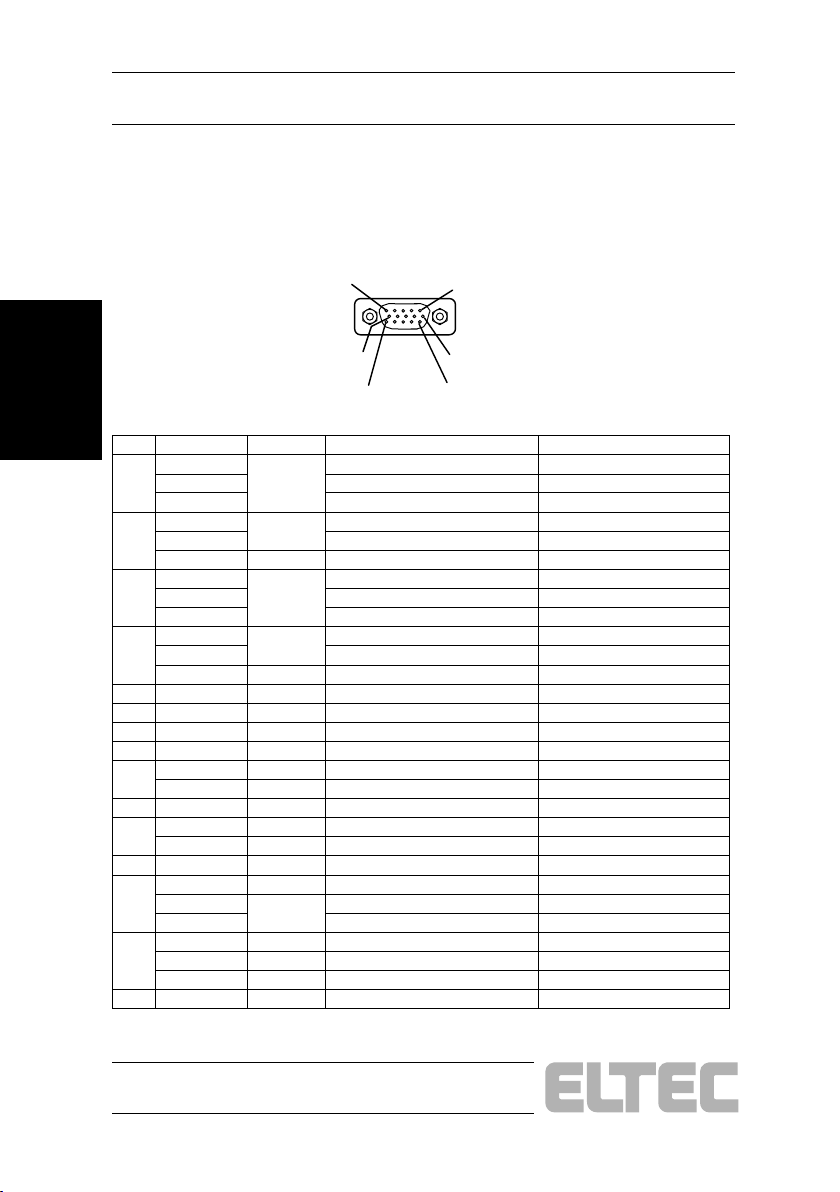
Table 2—1: Layout 15-pin VGA-Type Connector X100
(only PC_EYE 250)
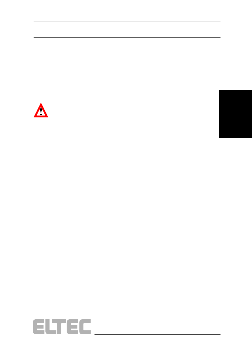
Table 2—2: Layout 15-pin VGA-Type Connector X101 ............... 2—6
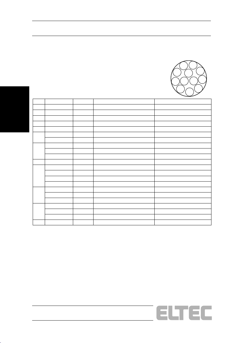
Table 2—3: Layout Hirose Connector X102................................. 2—8
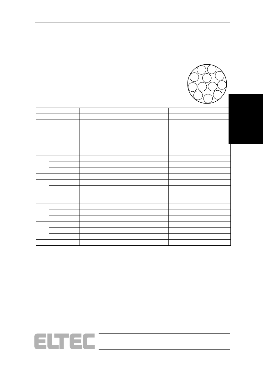
Table 2—4: Layout Hirose Connector X103................................. 2—9
Table 2—5: Layout Hirose Connector X104............................... 2—10
Table 2—6: Layout Hirose Connector X105............................... 2—11
Table 2—7: Layout 10-Pin Header X106.................................... 2—12
Table 2—8: Layout 3,5" Floppy-Type Power Connector X700 .. 2—12
Table 3—1: Electrical Specifications ............................................ 3—1
.................................................. 2—5
PC_EYE®2+
III
Page 6

Table of Contents User's Manual
List of Figures
Figure 1—1: Block Diagram PC_EYE 250 ................................... 1—2
Figure 1—2: Block-Diagram PC_EYE 260 ................................... 1—3
Figure 1—3: Opto-coupled Trigger Input Schematic.................... 1—6
Figure 2—1: Jumpers and Connectors Placement PC_EYE 250 2—4
Figure 2—2: Jumpers and Connectors Placement PC_EYE 260 2—4
Figure 2—3: PC_EYE 250/260 LED........................................... 2—16
Figure 4—1: Grabber Configuration ............................................. 4—2
IV
PC_EYE®2+
Page 7

Introduction User's Manual
1 Introduction
1.1 Technical Highlights
· Frame grabber for 4 simultaneous mono-chrome channels or one
RGB and one mono-chrome channel
· Digitizes up to four parallel, separate images from synchronized
cameras
· Restart cameras supported
· Real-time acquisition of images or image sequences directly into
main memory
· Image memory formats include RGB, monochrome with 32, 24, 16
or 8 bits/pixel
· PCI 2.2 compliant
Introduction
PC_EYE®2+
1—1
Page 8
Introduction User's Manual
A
A
A
A
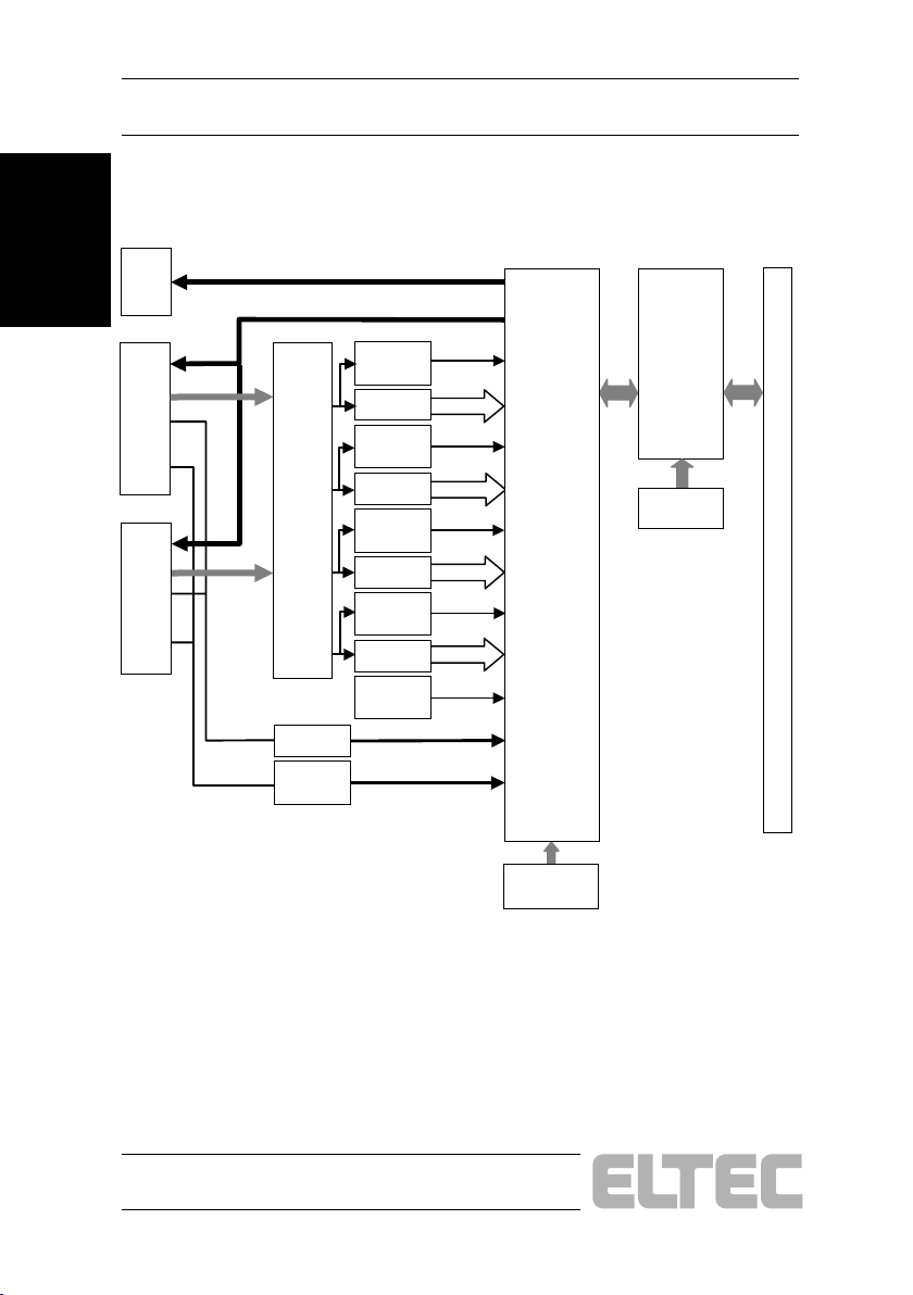
Figure 1—1: Block Diagram PC_EYE 250
10 pin
Header
Introduction
Input
A
15 pin
HD
Input
B
15 pin
HD
MUX
4 x
4:1
Opto
Clock
Restoration
GPO (12..15)
GPO (0, 1, 3, 4)
Sync0
Sync-
detect
/D
I0/R(0..7)
Sync1
Sync-
detect
/D
I1/G(0..7)
Sync2
Sync-
detect
/D
I2/B(0..7)
Sync3
Sync-
detect
I3(0..7)
/D
Sync4
Sync-
detect
Ext-Trigg er(0..3)
Ext-Clock(0..1)
FPGA-2
DMA-
Controller
Frontend
ICD2061
FPGA-1
PCI-Core
EE-Prom
PCIBUS
1—2
PC_EYE®2+
Page 9
A
A
A
A
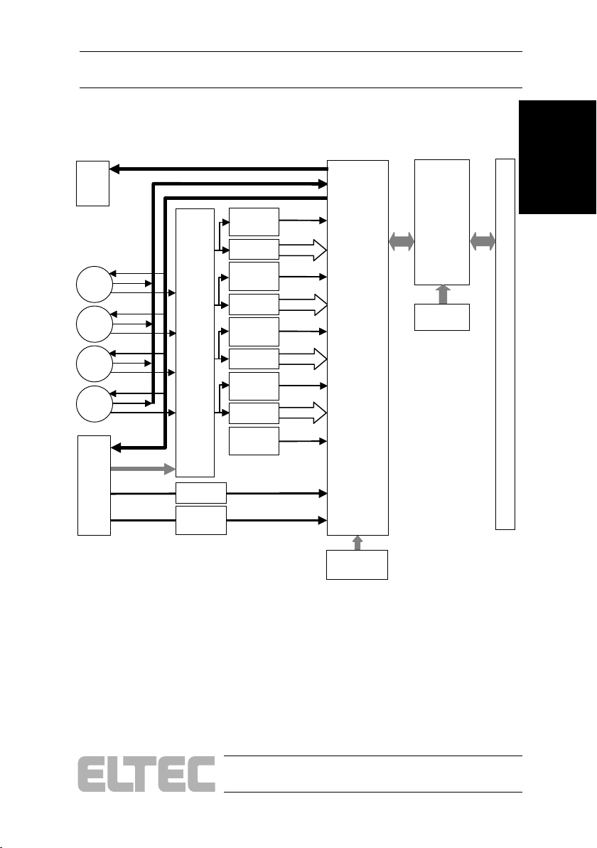
Figure 1—2: Block-Diagram PC_EYE 260
Introduction User's Manual
10 pin
Header
Hirose
X102
X103
X104
X105
Input
B
15 pin
HD
MUX
4 x
4:1
Opto
Clock
Restoration
GPO (12..15)
GPI (0..3)
GPO (0..11)
Sync0
Sync-
detect
/D
I0/R(0..7)
Sync1
Sync-
detect
/D
I1/G(0..7)
Sync2
Sync-
detect
/D
I2/B(0..7)
Sync3
Sync-
detect
I3(0..7)
/D
Sync4
Sync-
detect
Ext-Trigg er(0..3)
Ext-Clock(0..3)
FPGA-2
DMA-
Controller
Frontend
ICD2061
FPGA-1
PCI-Core
EE-Prom
PCIBUS
Introduction
PC_EYE®2+
1—3
Page 10

Introduction
Introduction
User's Manual
1.2 Technical Details
The PC_EYE®2+ is intended for applications where up to four parallel
channels are digitized, such as RGB data with additional alpha channel or
four monochrome synchronous cameras are used ("quadro", analogous to
stereo). It permits connection of RGB cameras.
In quadro mode, the four images are stored in separate memory regions as
separate monochrome images. Cameras must be synchronized for this
operating mode. An on-board sync generator with four separate 75-ohm
outputs makes this easy.
The pixel clock is divided down from a internal Oscillator (up to 180 MHz)
or it is taken directly from the pixel clock input for camera synchronous
digitization. The A/D conversion rates programmable up to 32 MHz.
The region of interest, i.e. the part of the video information that is acquired,
can be defined on a pixel basis for all 4 video inputs with the same values not always the full frame has to be acquired.
A Sequencer is included to met the different timings from restart cameras.
1—4
PC_EYE®2+
Page 11
Introduction User's Manual
1.2.1 Video Input
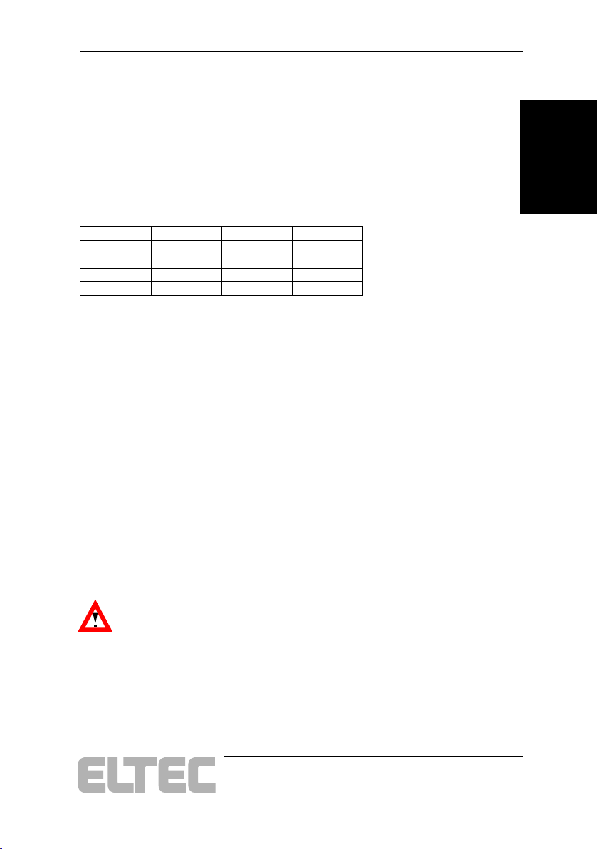
The eight video inputs are AC-coupled and terminated with 75 Ohm
resistors. Four independent Multiplexes distribute the signal to the four A/D
converters.
Table 1—1: Possible Input Selections
Converter 0 Converter 1 Converter 2 Converter 3
Video0 Video1 Video2 Video3
Video4 Video5 Video6 Video7
Video2 Video3 Video0 Video1
Video6 Video7 Video4 Video5
1.2.2 Sync Input
The Sync-input is Composite-Sync and taken from one of the multiplexed
Video-inputs or directly from Video7.
1.2.3 Clock Input
When cameras with clock-output are used, the pixel clock may taken from
the camera. The external clock is AC-coupled and restored to TTL-Level.
To compensate different delays between the Video- and the clock-input, the
phase of the clock can be shifted in steps of 90°.
Introduction
The clock input is single-ended TTL; it is terminated at the receiving end
(PC_EYE input), with 75 Ohm resistor. How to activate the input see
el_SetVideoFormat.
Caution: Use a separate shielded cable for clock to minimize crosstalk to video.
PC_EYE®2+
1—5
Page 12
Introduction
User's Manual
Introduction
1.2.4 Trigger Input
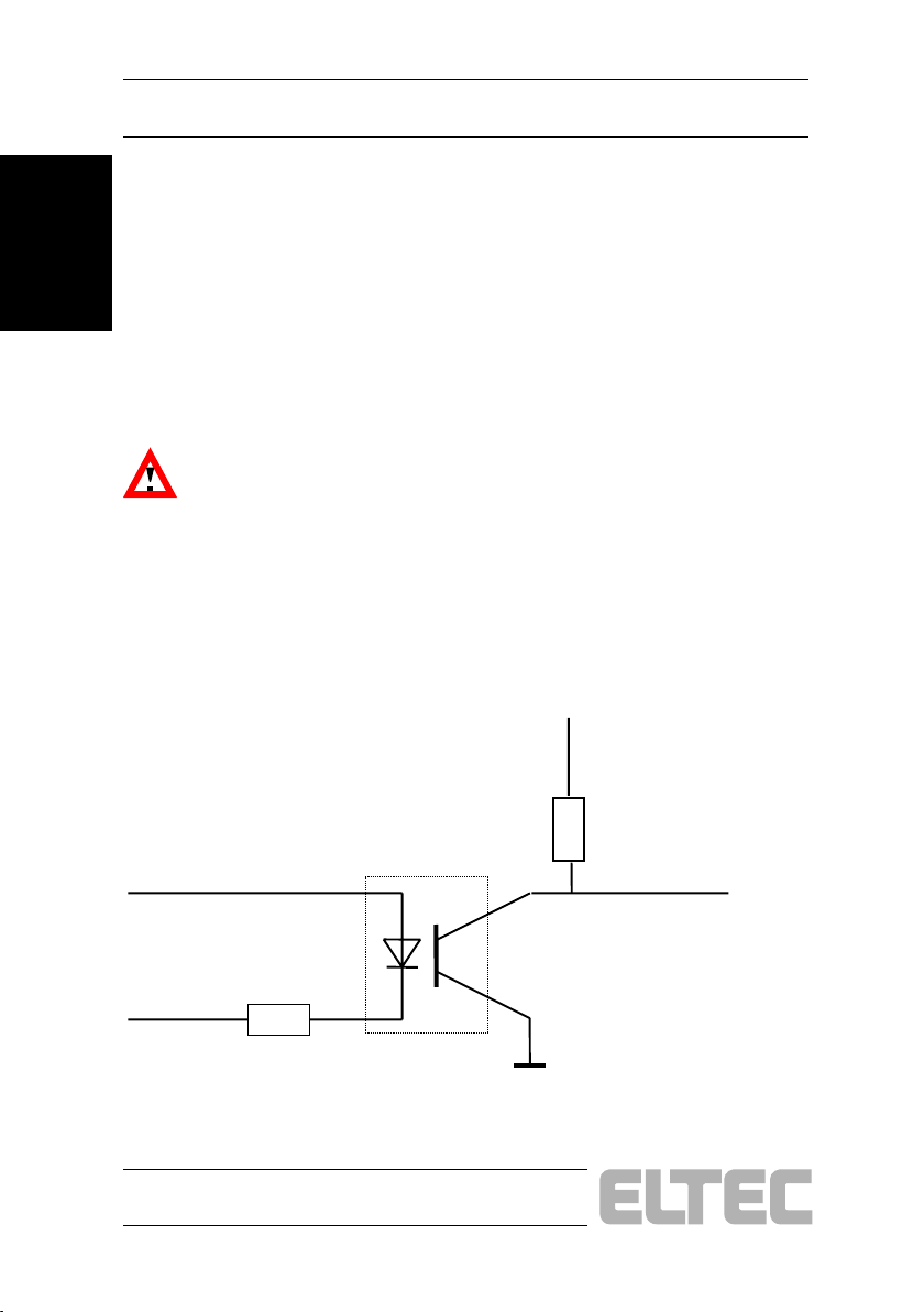
The trigger inputs are opto-decoupled for optimum noise immunity (250 V
isolation voltage). TRIGIN+ is connected to the anode of a LED, TRIGINto the cathode of the LED via an internal 220-Ohm resistor. Since the LED
needs about 10..20 mA for full drive, a 5 V voltage source or a TTL output
is able to drive sufficient current through the circuit. Higher-voltage sources
may be used with additional limiting resistors. This trigger input is levelsensitive: a high (current is on) will activate continuous snaps; current must
be off to block the acquisition. See also: el_SetVideoFormat
Caution: Do not exceed a maximum of 30 mA LED current!
Alternativly the Optocoupler can be bypassed. In this case the trigger
function is inverted.
Figure 1—3: Opto-coupled Trigger Input Schematic
Trigger +
Trigger -
1—6
220 Ohm
Optocoupler
PC_EYE®2+
Trigger int.
Page 13

User's Manual
Introduction
1.2.5 Sync / Camera Control Output
For sync and camera control are up to 16 General-Proposes-Outputs
available. The first 12 GPOs are more flexible then the other 4 outputs.
1.2.5.1 Sync / Camera Control Output 0..11
Each Output can be mapped to one of 8 available signals:
· Static output
· Sync-generator Horizontal-sync
· Sync-generator Vertical-sync
· Internal Trigger
· Sequencer bit 2
· Sequencer bit 3
· Sequencer bit 4
· Sequencer bit 5
The logical polarity (High-/ Low-active) is for every Output independently
programmable.
oduc
Intr tion
1.2.5.2 Sync / Camera Control Output 12..15
Each one of this 4 outputs can be set to static low or high.
1.2.6 Power Supply out
To supply the cameras with Power, they are up to 4 Outputs with 12 V.
Each Output is protected with a self healing (PTC) 1100 mA fuse.
PC_EYE®2+
1—7
Page 14

Introduction
Introduction
User's Manual
1.2.7 Data Transfer
Since the PC_EYE-2+ is a Busmaster card, the video data from a Frame or
a whole sequence is moved to memory per DMA-transfer. No need for the
CPU to support this process. The maximum transfer rate in a system is 105
Mbytes/s, but this is a best case. In a real application the transfer rate is
depend of the chipset, graphic card and other active Busmaster cards.
1—8
PC_EYE®2+
Page 15

Introduction User's Manual
1.2.8 Packing Modes
There are 8 different modes handle several combinations of cameras
1.2.8.1 Mode Mono
Four individual monochrome channels, each 8 bit per Pixel.
1.2.8.2 Mode RGB24
One 24 bit RGB channel, packed in 32 bit.
1.2.8.3 Mode RGB32_Z
One 24 bit RGB channel stored as 32 bit, the 8 unused high order bits are
zero.
1.2.8.4 Mode RGB32_3
One 24 bit RGB channel stored as 32 bit. In the 8 high order bits (Alpha
channel) is monochrome channel 3 stored.
Introduction
1.2.8.5 Mode RGB555
One 15 bit RGB channel stored as 16 bit, the MSB is zero.
One 8 bit monochrome channel.
1.2.8.6 Mode RGB565
One 16 bit RGB channel stored as 16 bit.
One 8 bit monochrome channel.
PC_EYE®2+
1—9
Page 16

Introduction
Introduction
1.2.8.7 Mode RGB555M
One monochrome channel, stored as 15 bit RGB. In a 16 bit word the MSB
is zero.
Two 8 bit monochrome channels.
1.2.8.8 Mode RGB565M
One monochrome channel, stored as 16 bit RGB.
Two 8 bit monochrome channels.
User's Manual
1—10
PC_EYE®2+
Page 17

Hardware Installation User's Manual
2 Hardware Installation
What you need for installation and use of the PC_EYE family member
boards:
· PC with free PCI slot and Pentium (I -III) CPU.
· The PC_EYE board.
· PC_EYE2+: video camera appropriate for the PC_EYE2+
(monochrome). Mainboard with good PCI throughput because of
high bandwide needs
· Windows 98, ME, NT or 2000 operating system.
· Operation system dependent hardware driver setup and system
independent development files setup, downloaded from the internet
or obtained on CD.
2.1 Installation Procedure:
· Switch off computer,
Hardware
Installation
· Prepare site to observe electrostatic discharge (ESD) precautions
before opening computer or removing PC_EYE from its case: Touch
computer steel case during insertion/removal of PC_EYE or take
other precautions to ensure the absence of high voltages due to
electric charges.
· Open computer case,
· Remove blind back panel,
· Insert PC_EYE board into free PCI slot; the PC_EYE board must fit
into the slot without use of excessive force, make sure it sits firmly
in the slot and the PCI connector’s conductors sit completely inside
the connector.
· Fix PC_EYE back panel with screw,
· Close case,
PC_EYE®2+
2—1
Page 18

Hardware Installation
· Attach video (camera) cables - for a quick start and a first test
camera input #0 should be used with the video camera in freerunning mode. The camera should be known to deliver video signals
(testing can be done by feeding the camera signal to an appropriate
video monitor). See also: Connectors
User's Manual
Installation
Hardware
2.2 Cable
PC_EYE 250
To connect a RGB-Camera, use a standard PC-Monitor cable HD15 to
BNC.
To connect four monochrome cameras with BNC-Output use the ELTEC
cable V-CABL-183A.
PC_EYE 260
To connect four monochrome cameras with Hirose-Output use a standard
Hirose-Cable.
2—2
PC_EYE®2+
Page 19

User's Manual
Hardware Installation
2.3 Trouble Shooting - if it does not
work
Check if the driver and the user mode software are installed properly. See
chapter 3.
Grabber is not found by software:
Make sure the grabber is correctly plugged into the PCI-connector. If
mechanical problems can be excluded refer to the driver installation guide
to see if the driver has been installed correctly. Mixing up the recommended
installation order of hard and software can be a possible reason for an
incorrectly installed driver.
Rolling, corrupted image:
If a live image is visible after starting CFG2P, but it is rolling, this may
indicate that the PCI bus speed is not fast enough. Changing the BIOS setup
may help. If not, the motherboard chip set might be to slow. This is
especially true if a stable image can be seen with smaller horizontal regionof-interest (ROI) settings. Try switching off live mode in CFG2P.If the
image is corrupted and there is no dependency from the horizontal
acquisition width, the graphics board may be responsible for long PCI
blocking times. Disabling video acceleration in the control panel may help;
additionally, switching to a lower pixel depth (8 bpp instead of 16 or 24)
can be helpful.
Getting support:
Under some circumstances (hopefully rare ones...) you may not succeed in
getting everything running. Then you can contact us - but we need the
system configuration as exactly as possible. For that purpose we have
prepared a support request form where you can fill in your configuration
and submit this form (by fax or E-mail) together with the support request using this form will help us to help you faster.
are
Hardw
Installation
PC_EYE®2+
2—3
Page 20
Hardware Installation User's Manual
2.4 Connectors
The 15-pin female D connector is used to input video signals and several
other I/Os.
Installation
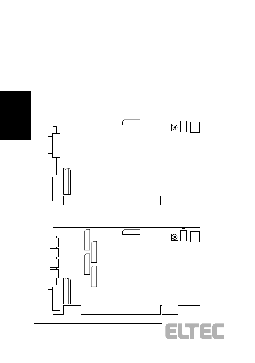
2.4.1 Jumpers and Connectors Placement
Hardware
Figure 2—1: Jumpers and Connectors Placement PC_EYE 250
X100
J104..6
X101
X106
S500
LED
D601
X700
Figure 2—2: Jumpers and Connectors Placement PC_EYE 260
S500
LED
D601
X700
X102
X103
X104
X105
J104..6
J100
J102
X106
J101
J103
X101
2—4
PC_EYE®2+
Page 21
Hardware Installation User's Manual
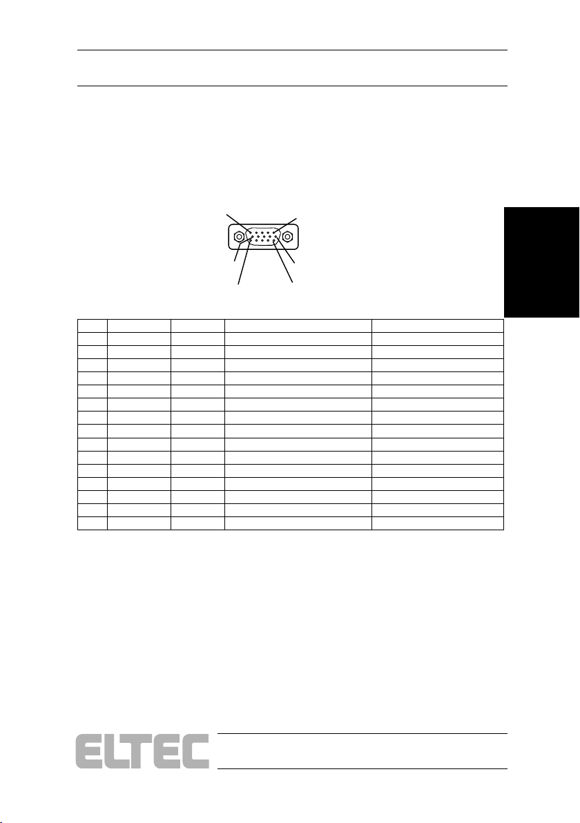
2.4.2 Connector X100
Table 2—1: Layout 15-pin VGA-Type Connector X100
(only PC_EYE 250)
Front view
Pin5
Pin1
Pin10
Pin15
Pin6
Pin11
Pin Signal Direction Description Level
1
Video0 Input Video Red or BW0 0.7 Vpp Video 0.3 Vpp Sync
2
Video1 Input Video input Green or BW1 0.7 Vpp Video 0.3 Vpp Sync
3
Video2 Input Video input Blue or BW2 0.7 Vpp Video 0.3 Vpp Sync
4
Video3 Input Video input Alpha or BW3 0.7 Vpp Video 0.3 Vpp Sync
5
GND - Signal ground 0 V
6
GND - Signal ground 0 V
7
GND - Signal ground 0 V
8
GND - Signal ground 0 V
9
TRIG+0 - Trigger high-level TTL high
10
GND - Signal ground 0 V
11
TRIG-0 Input Trigger low-level TTL low
12
EXTCLK0 Input External clock, max. 32 MHz TTL, rising edge
13
GPO0 Output Sync or Camera Control 0 TTL 3.2 V @ 75 Ohm
14
GPO1 Output Sync or Camera Control 1 TTL 3.2 V @ 75 Ohm
15
PVcc Output Fused Supply for Cameras 12 V, 1100 mA
Hardware
Installation
PC_EYE®2+
2—5
Page 22
Hardware Installation
User's Manual
2.4.3 Connector X101
Table 2—2: Layout 15-pin VGA-Type Connector X101
Front view
Pin5
Installation
Hardware
Pin10
Pin15
Pin1
Pin6
Pin11
Pin Signal Direction Description Level
1
Video4 Video Red_B or BW0_B 0.7 Vpp Video 0.3 Vpp Sync
EXTTRIG+2 Differencial Trigger high TTL high
EXTTRIG2
2
Video5 Video input Green_B or BW1_B 0.7 Vpp Video 0.3 Vpp Sync
EXTTRIG-2
GPO2 Output Sync or Camera control 2 TTL 3.2 V @ 75 Ohm
3
Video6 Video input Blue_B or BW2_B 0.7 Vpp Video 0.3 Vpp Sync
EXTTRIG+3 Differencial Trigger high TTL high
EXTTRIG3
4
Video7 Video input Alpha_B or BW3_B 0.7 Vpp Video 0.3 Vpp Sync
EXTTRIG-3
GPO5 Output Sync or Camera control 5 TTL 3.2 V @ 75 Ohm
5
GND - Signal ground 0 V
6
GND - Signal ground 0 V
7
GND - Signal ground 0 V
8
GND - Signal ground 0 V
9
EXTTRIG+1 Input Differencial Trigger high TTL high
EXTTRIG1 Input Trigger TTL high
10
GND - Signal ground 0 V
11
EXTTRIG-1 Input Trigger TTL high
GPO11 Output Sync or Camera control 11 TTL 3.2 V @ 75 Ohm
12
EXTCLK_1 Input External clock, max. 32 MHz TTL, rising edge
13
GPO3 Output Sync or Camera control 0 TTL
EXTTRIG+0 Differencial Trigger high TTL high
EXTTRIG0
14
GPO4 Output Sync or Camera control 1 TTL 2.7 V @ 75 Ohm
EXTTRIG-0 Input Differencial Trigger low TTL low
GPO8 Output Sync or Camera control 8 TTL 2.7 V @ 75 Ohm
15
PVcc_1 Output Fused supply for cameras 12 V, 1100 mA
Input
Trigger TTL high
Input
Differencial Trigger low TTL low
Input
Trigger TTL high
Input
Differencial Trigger low TTL low
Input
Trigger TTL high
2—6
PC_EYE®2+
Page 23
Hardware Installation User's Manual
All signals with 1.0 Vpp level are AC-coupled and terminated with 75 Ohm
to GND.
The connector case of all connector X100 and X101 is connected to shield
potential which is separated from signal ground. If only the video inputs are
required a standard VGA monitor cable with BNC connectors on the
monitor end may be used.
Power supply output: On pin 15 12V are delivered to supply the
video camera. The current that can be drawn from this pin is limited
with a PTC resistor (Imax ca. 1100 mA).
Hardware
Installation
PC_EYE®2+
2—7
Page 24
Hardware Installation
User's Manual
2.4.4 Connector Hirose X102
Table 2—3: Layout Hirose Connector X102
Installation
Hardware
Pin Signal Direction Description Level
1
GND - Signal Ground 0V
2
PVcc0 Output Fused Supply for Cameras 12 V, 1100 mA
3
GND - Signal Ground 0V
4
Video0 Input Video Input 0 0,7 Vpp Video, 0,3 Vpp Sync
5
GND - Signal Ground 0V
6
NC - - GPO0 Output Sync or Camera Control 0 TTL 3.2 V @ 75 Ohm
7
NC - - GPO1 Output Sync or Camera Control 1 TTL 3.2 V @ 75 Ohm
EXTCLK0 Input External Clock 0, max. 32 MHz TTL
8
GND - Signal Ground 0V
9
NC - - GPO2 Output Sync or Camera Control 2 TTL 3.2 V @ 75 Ohm
EXTCLK0 Input External Clock 0, max. 32 MHz TTL
Video5 Input Video Input 5 0,7 Vpp Video, 0,3 Vpp Sync
10
NC - - GND - Signal Ground 0V
GPI0 Input General Purpose Input 0 TTL
11
NC - - PVcc Output Fused Supply for Cameras 12 V, 1100 mA
GPO2 Output Sync or Camera Control 2 TTL
12
GND - Signal Ground 0V
3
9
1
2
4
8
10
7
12
11
6
5
2—8
PC_EYE®2+
Page 25
Hardware Installation User's Manual
2.4.5 Connector Hirose X103
Table 2—4: Layout Hirose Connector X103
Pin Signal Direction Description Level
1
GND - Signal Ground 0V
2
PVcc1 Output Fused Supply for Cameras 12 V, 1100 mA
3
GND - Signal Ground 0V
4
Video1 Input Video Input 1 0,7 Vpp Video, 0,3 Vpp Sync
5
GND - Signal Ground 0V
6
NC - - GPO3 Output Sync or Camera Control 3 TTL 3.2 V @ 75 Ohm
7
NC - - GPO4 Output Sync or Camera Control 4 TTL 3.2 V @ 75 Ohm
EXTCLK1 Input External Clock 0, max. 32 MHz TTL
8
GND - Signal Ground 0V
9
NC - - GPO5 Output Sync or Camera Control 5 TTL 3.2 V @ 75 Ohm
EXTCLK1 Input External Clock 1, max. 32 MHz TTL
Video6 Input Video Input 6 0,7 Vpp Video, 0,3 Vpp Sync
10
NC - - GND - Signal Ground 0V
GPI1 Input General Purpose Input 1 TTL
11
NC - - PVcc Output Fused Supply for Cameras 12 V, 1100 mA
GPO5 Output Sync or Camera Control 5 TTL
12
GND - Signal Ground 0V
1
2
10
11
3
4
9
8
7
12
6
5
Hardware
Installation
PC_EYE®2+
2—9
Page 26
Hardware Installation
User's Manual
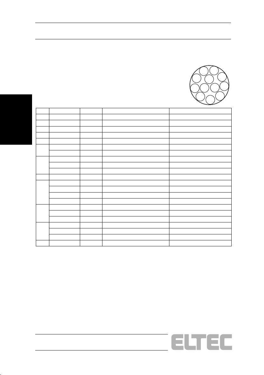
2.4.6 Connector Hirose X104
Table 2—5: Layout Hirose Connector X104
Installation
Hardware
Pin Signal Direction Description Level
1
GND - Signal Ground 0V
2
PVcc2 Output Fused Supply for Cameras 12 V, 1100 mA
3
GND - Signal Ground 0V
4
Video2 Input Video Input 2 0,7 Vpp Video, 0,3 Vpp Sync
5
GND - Signal Ground 0V
6
NC - - GPO6 Output Sync or Camera Control 6 TTL 3.2 V @ 75 Ohm
7
NC - - GPO7 Output Sync or Camera Control 7 TTL 3.2 V @ 75 Ohm
EXTCLK2 Input External Clock 2, max. 32 MHz TTL
8
GND - Signal Ground 0V
9
NC - - GPO8 Output Sync or Camera Control 8 TTL 3.2 V @ 75 Ohm
EXTCLK2 Input External Clock 2, max. 32 MHz TTL
Video7 Input Video Input 7 0,7 Vpp Video, 0,3 Vpp Sync
10
NC - - GND - Signal Ground 0V
GPI2 Input General Purpose Input 2 TTL
11
NC - - PVcc Output Fused Supply for Cameras 12 V, 1100 mA
GPO8 Output Sync or Camera Control 8 TTL
12
GND - Signal Ground 0V
9
1
2
3
4
8
10
7
12
11
6
5
2—10
PC_EYE®2+
Page 27
Hardware Installation User's Manual
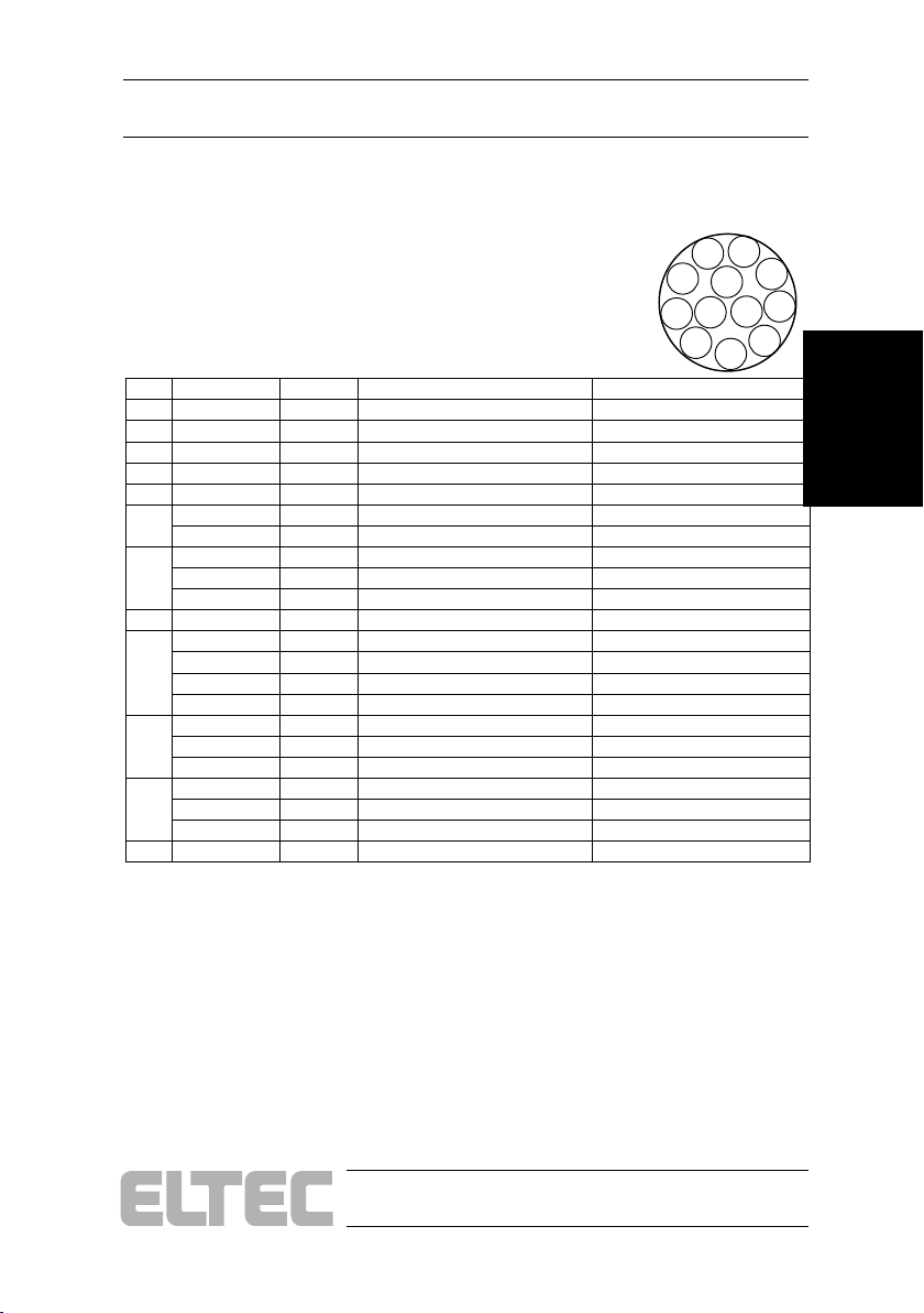
2.4.7 Connector Hirose X105
Table 2—6: Layout Hirose Connector X105
Pin Signal Direction Description Level
1
GND - Signal Ground 0V
2
PVcc3 Output Fused Supply for Cameras 12 V, 1100 mA
3
GND - Signal Ground 0V
4
Video3 Input Video Input 3 0,7 Vpp Video, 0,3 Vpp Sync
5
GND - - -
6
NC - - GPO9 Output Sync or Camera Control 9 TTL 3.2 V @ 75 Ohm
7
NC - - GPO10 Output Sync or Camera Control 10 TTL 3.2 V @ 75 Ohm
EXTCLK3 Input External Clock 3, max. 32 MHz TTL
8
GND - Signal Ground 0V
9
NC - - GPO11 Output Sync or Camera Control 11 TTL 3.2 V @ 75 Ohm
EXTCLK3 Input External Clock 3, max. 32 MHz TTL
Video4 Input Video Input 4 0,7 Vpp Video, 0,3 Vpp Sync
10
NC - - GND - Signal Ground 0V
GPI3 Input General Purpose Input 3 TTL
11
NC - - PVcc Output Fused Supply for Cameras 12 V, 1100 mA
GPO11 Output Sync or Camera Control 11 TTL
12
GND - Signal Ground 0V
1
2
10
11
3
4
9
8
7
12
6
5
Hardware
Installation
PC_EYE®2+
2—11
Page 28
Hardware Installation
User's Manual
2.4.8 Connector 10-Pin Header X106
Table 2—7: Layout 10-Pin Header X106
Pin Signal Direction Level
1 GPIO Output
2 GND 0 V 3 GPIO13 Output
Installation
4 GND 0 V -
Hardware
5 GPIO14 Output
6 GND 0 V 7 GPIO15 Output
8 GND 0 V 9 GND 0 V 10 GND 0 V -
TTL 3.2 V @ 75 Ohm
TTL 3.2 V @ 75 Ohm
TTL 3.2 V @ 75 Ohm
TTL 3.2 V @ 75 Ohm
2.4.9 Connector X700
Table 2—8: Layout 3,5" Floppy-Type Power Connector X700
Pin Signal Direction Description Level
1
NC - Not connected -
2
GND - Power ground 0 V
3
GND - Power ground 0 V
4
12 V Input Power for Cameras 12 V, 4,4 A
2.5 Switches
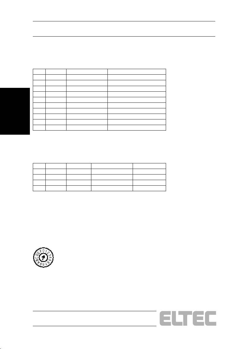
Switch S500 is used to set the PC_EYE2+ board ID. If more than one
PC_EYE2+ is plugged into the PC, they must have distinct board IDs
unequal to "0".
2—12
PC_EYE®2+
Page 29
Hardware Installation User's Manual
A
A
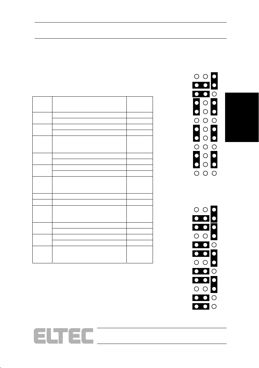
2.6 Jumpers
2.6.1 Jumper J104
Jumpering for X101
Pin on
HD15
X101
Video Input 4 * 10A - 11A
External Trigger 2 TTL 11A - 12A
Video Input 5 * 10C - 11C
1 & 2
4 & 5
9
11
9 & 11
13 & 14
GPO2 10B - 10C
External Trigger 2 Differencial ** 11A - 11B,
Video Input 6 * 7A - 8A
External Trigger 3 TTL 8A - 9A
Video Input 7 * 7C - 8C
GPO5 7B - 7C
External Trigger 3 Differencial ** 8A - 8B,
External Trigger 1 TTL 2A - 3A
GPO11 1B - 1C
External Trigger 1 Differencial * / ** 2A - 2B,
GPO3 * 4A - 5A
External Trigger 0 TTL 5A - 6A
GPO4 * 4C - 5C
GPO8 4B - 4C
External Trigger 0 Differencial * 5A - 5B,
* Default jumpering PC_EYE 250
** Default jumpering PC_EYE 260
Used Signal Jumper
Closed
12A - 12B,
9C - 10C
9A - 9B,
6C - 7C
3A - 3B,
1C - 2C
6A - 6B,
3C - 4C
Default Jump ering
1
2
3
4
5
6
7
8
9
10
11
12
Default Jumpering
1
2
3
4
5
6
7
8
9
10
11
12
PC_EYE 250
B C
PC_EYE 260
B
Hardware
Installation
C
PC_EYE®2+
2—13
Page 30
Hardware Installation
A
A
User's Manual
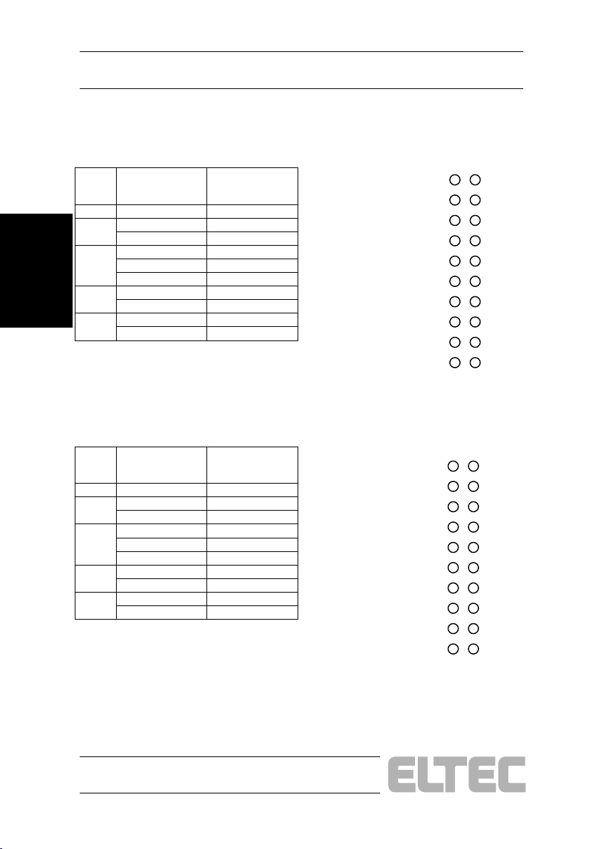
2.6.2 Jumper J100
Default Jumpering
left open all
Jumpering for X102
Pin on
Hirose
X102
6
Installation
7
Hardware
9
10
11
Used Signal Jumper Closed
GPO0 10A - 10B
GPO1 9A - 9B
External Clock 0 8A - 8B
GPO2 7A - 7B
External Clock 0 6A - 6B
Video Input 5 5A - 5B
GND 4A - 4B
GPI0 3A - 3B
+ 12 V 2A - 2B
GPO2 1A - 1B
10
B
1
2
3
4
5
6
7
8
9
2.6.3 Jumper J101
Jumpering for X103
Pin on
Hirose
X103
6
7
9
10
11
Used Signal Jumper Closed
GPO3 10A - 10B
GPO4 9A - 9B
External Clock 1 8A - 8B
GPO5 7A - 7B
External Clock 1 6A - 6B
Video Input 6 5A - 5B
GND 4A - 4B
GPI1 3A - 3B
+ 12 V 2A - 2B
GPO5 1A - 1B
Default Jumpering
left open all
B
1
2
3
4
5
6
7
8
9
10
2—14
PC_EYE®2+
Page 31
Hardware Installation User's Manual
A
A
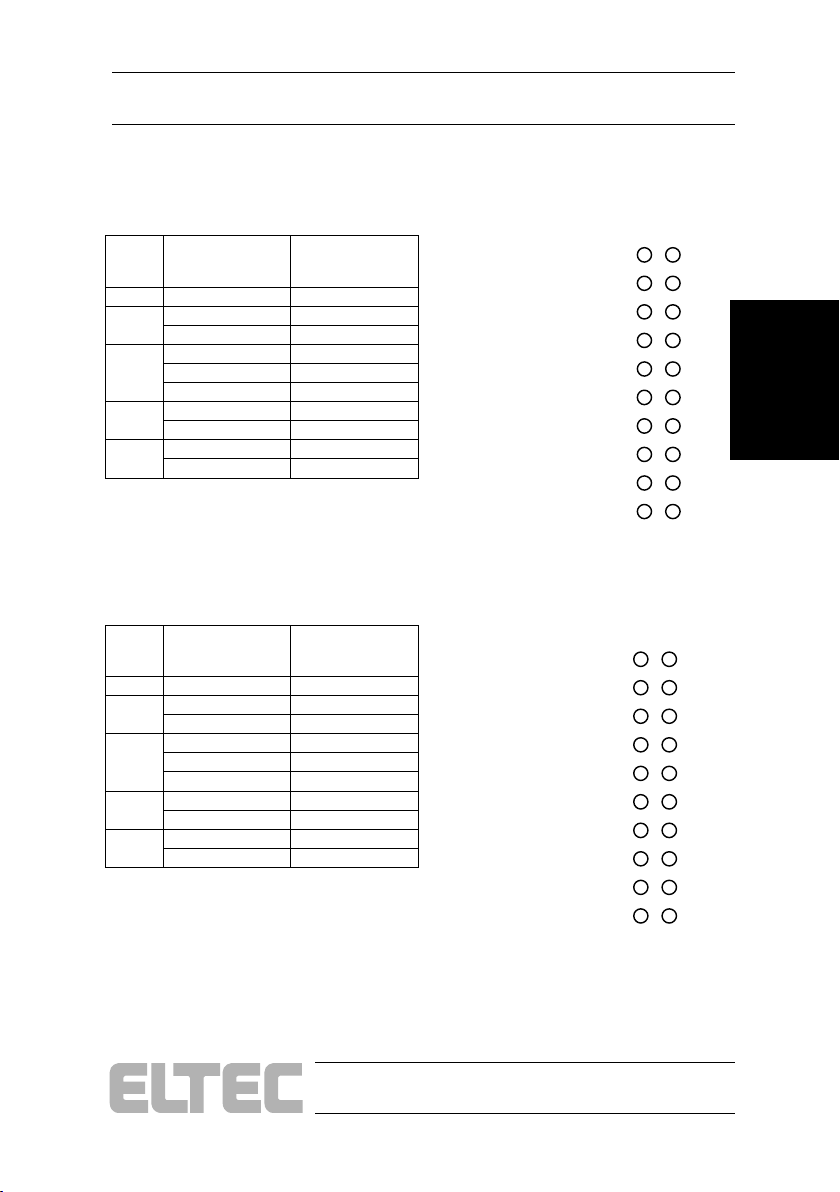
2.6.4 Jumper J102
Jumpering for X104
Pin on
Hirose
X104
6
7
9
10
11
Used Signal Jumper Closed
GPO6 10A - 10B
GPO7 9A - 9B
External Clock 2 8A - 8B
GPO8 7A - 7B
External Clock 2 6A - 6B
Video Input 7 5A - 5B
GND 4A - 4B
GPI2 3A - 3B
+ 12 V 2A - 2B
GPO8 1A - 1B
2.6.5 Jumper J103
Jumpering for X105
Pin on
Hirose
X105
6
7
9
10
11
Used Signal Jumper Closed
GPO9 10A - 10B
GPO10 9A - 9B
External Clock 3 8A - 8B
GPO11 7A - 7B
External Clock 3 6A - 6B
Video Input 8 5A - 5B
GND 4A - 4B
GPI3 3A - 3B
+ 12 V 2A - 2B
GPO11 1A - 1B
Default Jumpering
left open all
B
1
2
3
4
5
6
7
8
9
10
Default Jumpering
left open all
B
1
2
3
4
5
6
7
8
9
10
Hardware
Installation
PC_EYE®2+
2—15
Page 32
Hardware Installation
User's Manual
2.7 Status-LEDs
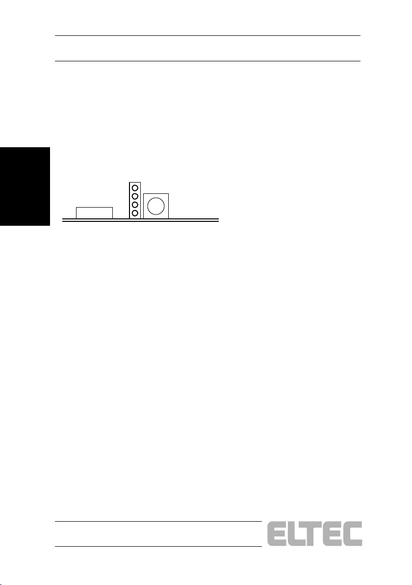
They are 4 LEDs for several status information:
Installation
Hardware
Figure 2—3: PC_EYE 250/260 LED
1
2
LED 1: Board selected - when the Configuration-Program is started, the
LED make a flash
LED 2: Capture - Acquisition in progress
LED 3: FiFo overrun - The FiFo run full
LED 4: FiFo Write Enable - valid data is written into the FiFo
3
4
2—16
PC_EYE®2+
Page 33
User's Manual
Specifications
3 Specifications
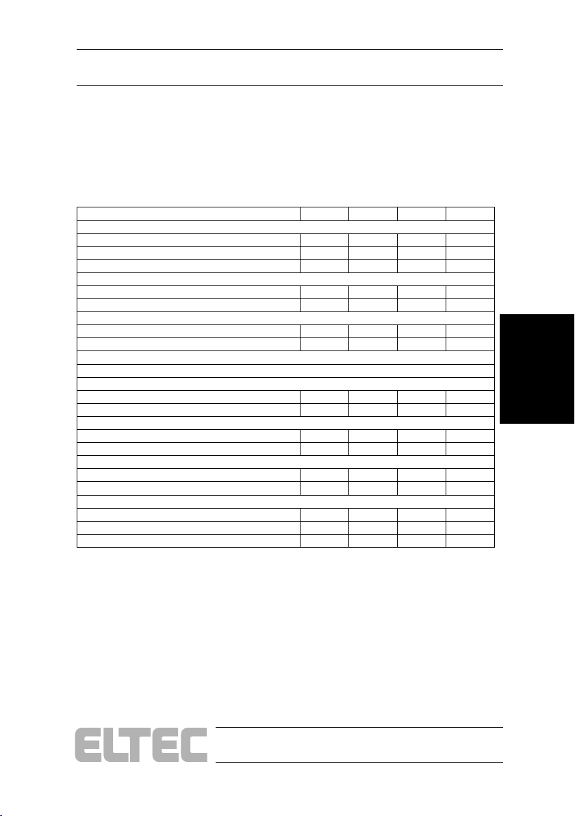
3.1 Electrical Specifications
Table 3—1: Electrical Specifications
Composite Video Input
video input Voltage 0.5 0.7 0.7 Vpp
sync input Voltage 0.15 0.3 0.4 Vpp
Offset input Voltage -4 +4 V
Clock
AC 0.2 5 Vpp
Offset+AC -4 4 V
Trigger Input
differential input voltage 2.0 7 Vpp
common input voltage -25 +25 V
Sync / Camera Control Output
@ 75 Ohm
output high voltage 3.0 3.15 3.75 V
output low voltage 0 0.1 V
@ 10 kOhm
output high voltage 3.3 3.6 4.0 V
output low voltage 0.0 0.1 V
Power Supply out
Output voltage 12 V
Output current 1.1 A
Power Requirement
Power Supply +5V (PCI-connector) 450 550 mA
Power Supply +12V (PCI-connector) 180 200 mA
Power Supply +12V (Power-connector) 4.4 A
Description Min. Typ. Max. Unit
Specifications
PC_EYE®2+
3—1
Page 34

Specifications User's Manual
3.2 Environmental Conditions
Storage Temperature: -20° C - 70° C
Operating Temperature: 0° C - 45°C (2 m/s forced air cooling)
Maximum Operating Humidity: 85 % relative
Specifications
3—2
PC_EYE®2+
Page 35

Software Installation User's Manual
4 Software Installation
The software consists of a development files setup and a hardware driver
setup.
The software can be downloaded at http://www.eltec.com in the
"support" menue under "Driver and Updates" or can be obtained as a CD on
demand.
The software consists of a development files setup and a hardware driver
setup.
Depending on the type of the grabber and the operation system used,
the hardware driver has to be installed before or after the hardware. Refer
to the driver installation guide to find out which component has to be
installed first.
If you face difficulties like that the grabber is not found by the software
make sure the driver is installed correctly.
Software
Installation
PC_EYE®2+
4—1
Page 36
Software Installation
User's Manual
4.1 Getting started
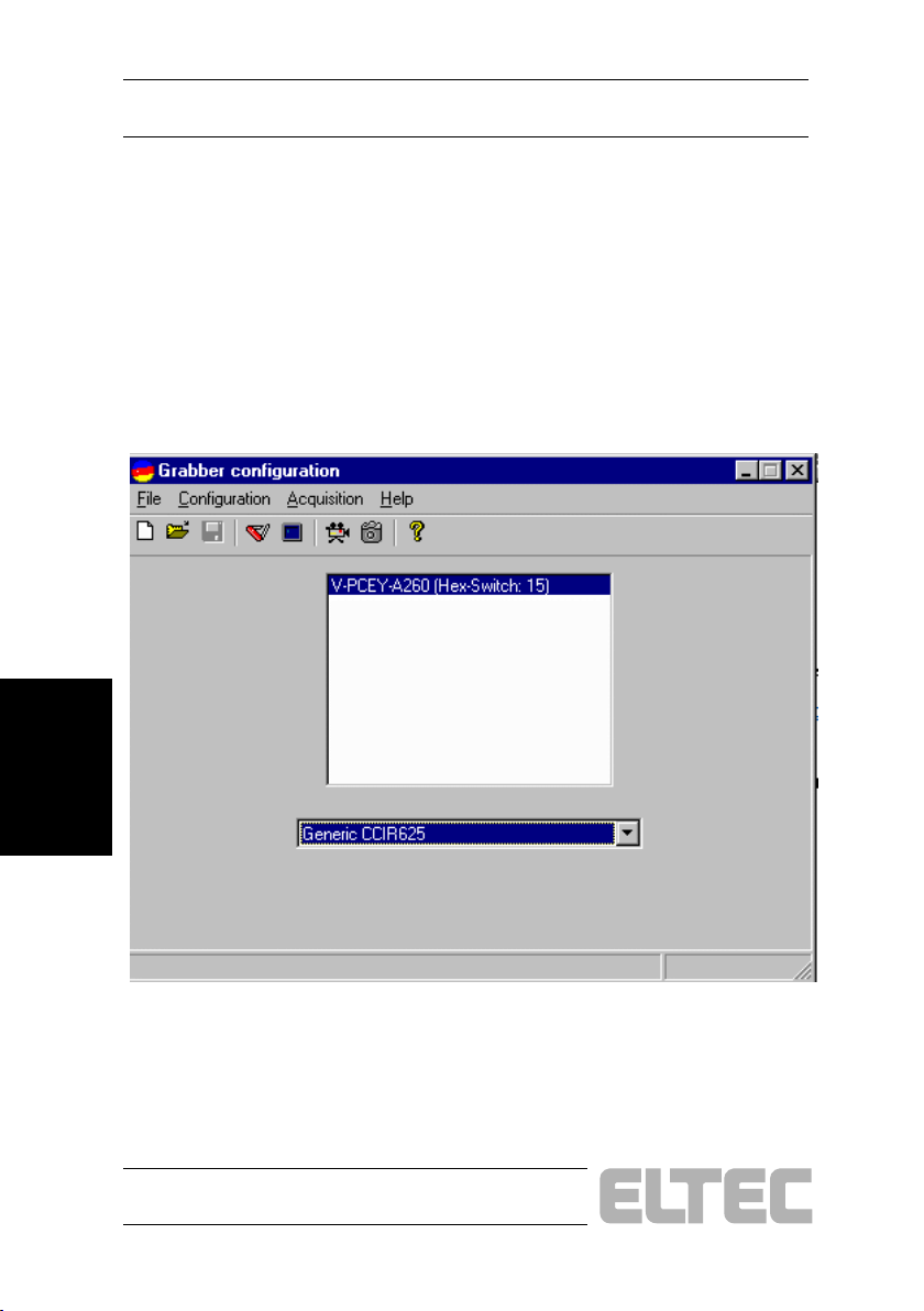
First the platform specific driver has to be installed . Please have a look to
the "drvinstall.pdf" help file. After that, by calling "app_setup.exe" the
PC_EYE 2+ Basic Tools and Configuration Program will be installed.
The Grabber Configuration Program is now ready to use.
Figure 4—1: Grabber Configuration
Installation
Software
4—2
PC_EYE®2+
Page 37
ELTEC Elektronik AG
_
_
_
_
_
_
_
_
_
Galile o -G alil ei-St r. 11
D-55129 Main z
Phone:
FAX:
email:
TECHNICAL ACTION REQUEST
+49 ( 0) 6131 918-520
+49 ( 0) 6131 918-196
[email protected]
Customer Name: Customer Ref. # :
Contact Name:
Phone Number:
Severity of Pr obl em: 1 . Critical 2. Serious 3. Major 4. Minor
Problem concerns: Hardware
Produc t:
ELTEC Serial No. (barcode ):
Op erating System :
Sy stem Conf igu ration (Hardware/Softwa re):
Motherboar d:
Mem or y Ca pac i t y: __ __ __ ___ __ __ __ ___ MB
PCI Slot 1: ____ __ __ ___ ____ __ __________
PCI Slot 2: ____ __ __ ___ ____ __ __________
PCI Slot 3: ____ __ __ ___ ____ __ __________
PCI Slot 4: ____ __ __ ___ ____ __ __________
ISA Slot 1: ____ __ __ ___ ____ __ __________
ISA Slot 2: ____ __ __ ___ ____ __ __________
ISA Slot 3: ____ __ __ ___ ____ __ __________
ISA Slot 4: ____ __ __ ___ ____ __ __________
___________________ ___ __ __ __ _______ ___________
___________________ ___
______________________
System
__________________________ ___ __ __ _
___________________________ __ ___ __ ___________________
Windows 98
___ ____ _____ ____ __ _____ ____ _____ BIO S: ____ _____ ____ __ _____ ___
Department:
FAX Number:
Windows NT
Product: _ ___ __ __ _______________________
Product: _ ___ __ __ _______________________
Product: _ ___ __ __ _______________________
Product: _ ___ __ __ _______________________
Product: _ ___ __ __ _______________________
Product: _ ___ __ __ _______________________
Product: _ ___ __ __ _______________________
Product: _ ___ __ __ _______________________
_________________________
_________________________
Software
Documentation
Revision Level: _________________
Other: _______________
 Loading...