

Page 1
G
Installation manual
MORI dMEV II - dMEV unit
Read this manual carefully before using the product and keep
it in a safe place for reference.
This product was constructed up to standard and in compliance
with regulations relating to electrical equipment and must be
installed by technically qualified personnel.
The manufacturer assumes no responsibility for damage to
persons or property resulting from failure to observe the
regulations contained in this booklet.
PRECAUTIONS FOR INSTALLATION, USE AND MAINTENANCE
• The device should not be used for applications other than those specified in this manual.
• After removing the product from its packaging, verify its condition. In case of doubt,
contact a qualified technician. Do not leave packaging within the reach of small children
or people with disabilities.
• Do not touch the appliance with wet or damp hands/feet.
• This appliance can be used by children aged from 8 years and above and persons with
reduced physical, sensory or mental capabilities or lack of experience and knowledge
if they have been given supervision or instruction concerning use of the appliance
in a safe way and understand the hazards involved. Children shall not play with the
appliance. Cleaning and user maintenance shall not be made by children without
supervision.
• Do not use the product in the presence of flammable vapours, such as alcohol,
insecticides, gasoline, etc.
• If any abnormalities in operation are detected, disconnect the device from the mains
supply and contact a qualified technician immediately. Use original spare parts only for
repairs.
• The electrical system to which the device is connected must comply with regulations.
• Before connecting the product to the power supply or the power outlet, ensure that:
- the data plate (voltage and frequency) correspond to those of the electrical mains
- the electrical power supply/socket is adequate for maximum device power. If not,
contact a qualified technician.
• The device should not be used as an activator for water heaters, stoves, etc., nor
should it discharge into hot air/fume vent ducts deriving from any type of combustion
unit. It must expel air outside via its own special duct.
• Operating temperature: 0°C up to +50°C.
• The device is designed to extract typical household air only, i.e. without excessive
grease, soot, chemical or corrosive agents, or flammable or explosive mixtures.
• Do not leave the device exposed to atmospheric agents (rain, sun, snow, etc.).
• Do not immerse the device or its parts in water or other liquids.
• Turn off the main switch whenever a malfunction is detected or when cleaning.
• For installation an omnipolar switch should be incorporated in the fixed wiring, in
accordance with the wiring regulations, to provide a full disconnection under overvoltage
category III conditions (contact opening distance equal to or greater than 3mm).
• If the supply cord is damaged, it must be replaced by the manufacturer, its service
Fig. 1
1
Page 2

agent or similarly qualified persons in order to avoid a hazard.
• Do not obstruct the fan or exhaust grille to ensure optimum air passage.
• Ensure adequate air return into the room in compliance with existing regulations in
order to ensure proper device operation.
• If the environment in which the product is installed also houses a fuel-operating device
(water heater, methane stove etc., that is not a “sealed chamber” type), it is essential
to ensure adequate air intake, to ensure good combustion and proper equipment
operation.
• Install the product so that the impeller is not accessible from the air outlet side as
verified by contact with the Test Finger (test probe “B” of the norm EN61032) in
compliance with the current safety regulations.
• Ceiling installation
In order to guarantee the IPX4 degree of protection against moisture in case of ceiling
installation, use the appropriate ceiling mount kit, which is included in the box. Use
only the rear entry hole for supply cables. If there is a possibility of condensation
along the air discharge duct, provide a drainage system to prevent condensation from
discharging into the environment through the fan.
Attention: do not mount the product on the ceiling without this kit.
• Window installation
In case of window installation it is necessary to use the appropriate window kit, which
is not included.
Attention: do not mount the product on the window without this kit.
INTRODUCTION
MORI dMEV (fig. 1) is a decentralised mechanical ventilation unit designed to ensure air
extraction in small/medium-sized rooms such as bathrooms, toilets and kitchens.
Suitable for air discharge directly to the outside or in the presence of short ducted system.
Wall, ceiling or window installation (fig. 2).
TECHNICAL SPECIFICATIONS
• Material: high quality, impact and UV-resistant ABS colour RAL 9010.
• Design front cover removable for cleaning without the use of tools.
• Rear reinforcement ring to prevent spigot deformation during installation.
• High efficiency aerodynamic fan with “winglet” blades to optimise quietness and
efficiency.
• Single phase EC Brushless motor with integral thermal protection.
• Motor mounted on high quality ball bearings.
• The fan is double insulated: no earth connection is required.
• Trickle speed selectable during installation.
• Option to boost from trickle (or from off) through LS connection or pull cord.
• Installation type selection available (through wall or ducted).
• Timer and Integral Humidistat versions available.
• IPX4 degree of protection.
•Power supply 220V to 240V~ 50Hz.
Model
MORI dMEV II T 83/47/29/21 23,1/13/8/6 27 2,5 26/23/13/11
MORI dMEV II HT 83/47/29/21 23,1/13/8/6 27 2,5 26/23/13/11
2
Airflow
m3/h l/s
Static pressure
Pa max
Power
W max
Sound pressure
dB(A) @3m
Page 3

VERSIONS
MORI dMEV II T (Timer version)
The fan is provided with over-run timer, adjustable from 0-30 minutes via a trimmer (fig.
17A). The fan works at the selected trickle speed (or off) and can be boosted using the
integrated pull cord switch or light switch. Once the boost switch is turned off the fan
will continue to run at the boost speed for the set period of time before reverting back
to the trickle speed.
The over-run timer function is activated only if the switch has been on for at least 60
seconds.
Pull Cord Operation: The pull cord works as the boost switch. Wire up as per diagram
(fig. 16A).
External Switch Operation: To boost the unit with an external switch such as a light
switch the pull cord should be disabled. To do this make sure the pull cord switch is
not on and simply cut the cord. The plastic caps on the wiring terminals will need to be
removed to allow the switch wires to be secured. Wire up as per diagram (fig. 16B).
External Switch and Pull Cord Operation: If the fan needs to be boosted via a pull cord
and external switch the switch used must be a double pole switch. This removes any
interference between the fan and the light. Wire up as per diagram (fig. 16B).
MORI dMEV II HT (Humidity control version)
The fan comes complete with an adjustable humidity sensor and adjustable timer. The
humidity threshold is adjustable from 50% to 95% Relative Humidity via a dedicated
trimmer, and the timer is adjustable from 0 - 30 minutes via a dedicated trimmer (fig. 17B).
The fan works at the selected trickle speed (or off) and can be boosted using the
integrated pull cord switch or light switch. Once the boost switch is turned off the fan will
continue to run at the boost speed for the set period of time before reverting back to the
trickle speed. There is also a comfort boost triggered by a humidity level above the set
threshold. The Comfort Boost flow rate is approximately half way between the pre-set
Background and Boost flow rate. Once the humidity level is below the set point the fan
will continue for a factory set period of time before returning to trickle speed.
To deactivate the humidistat function, turn the trimmer HY completely clockwise.
Pull Cord Operation: The pull cord works as the boost switch. Wire up as per diagram
(fig. 16D).
External Switch Operation: To boost the unit with an external switch such as a light
switch the pull cord should be disabled. To do this make sure the pull cord switch is
not on and simply cut the cord. The plastic caps on the wiring terminals will need to be
removed to allow the switch wires to be secured. Wire up as per diagram (fig. 16E).
External Switch and Pull Cord Operation: If the fan needs to be boosted via a pull cord
and external switch the switch used must be a double pole switch. This removes any
interference between the fan and the light. Wire up as per diagram (fig. 16E).
INSTALLATION TYPE SETTING
Installation type can be selected using the JUMPERS among different options. See fig. 18.
TRICKLE SPEED SETTING
Trickle speed can be selected using the JUMPERS among different options. See fig. 18.
Trickle speed can be also set to off.
3
Page 4
STANDARD CONFORMITY
2014/35/EU Low Voltage Directive (LVD)
2014/30/EU Electromagnetic Compatibility (EMC), in conformity with the following
standards:
Electrical Safety
EN60335-1(2012)+A11+A13; EN 60335-2-80(2003)+A1+A2.
Electromagnetic Compatibility
EN 55014-1(2017); EN 55014-2(2015); EN 61000-3-2(2014); EN 61000-3-3(2013).
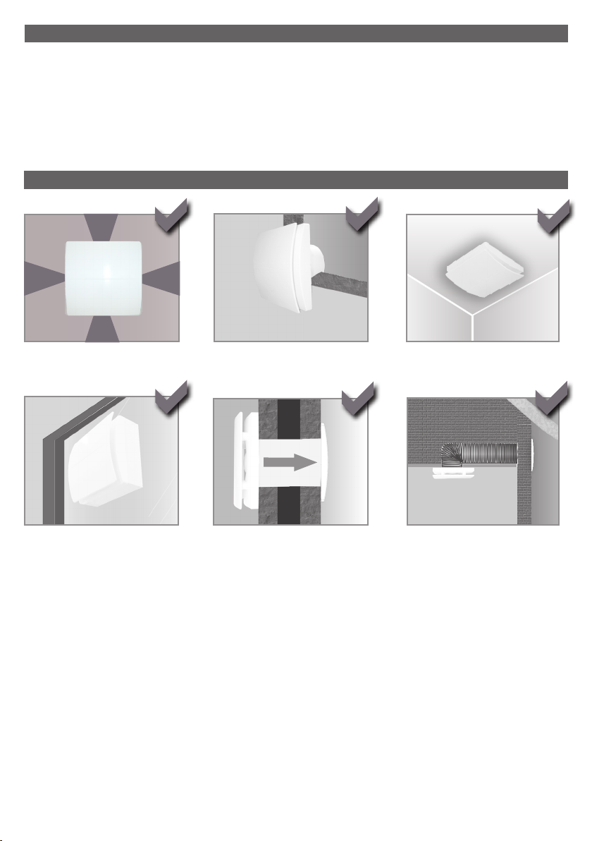
INSTALLATION (Fig.2)
perimetrical exhausting
window (kit on demand)
wall
direct exhausting
ceiling (accessory included in the box)
short ducting
4
Page 5
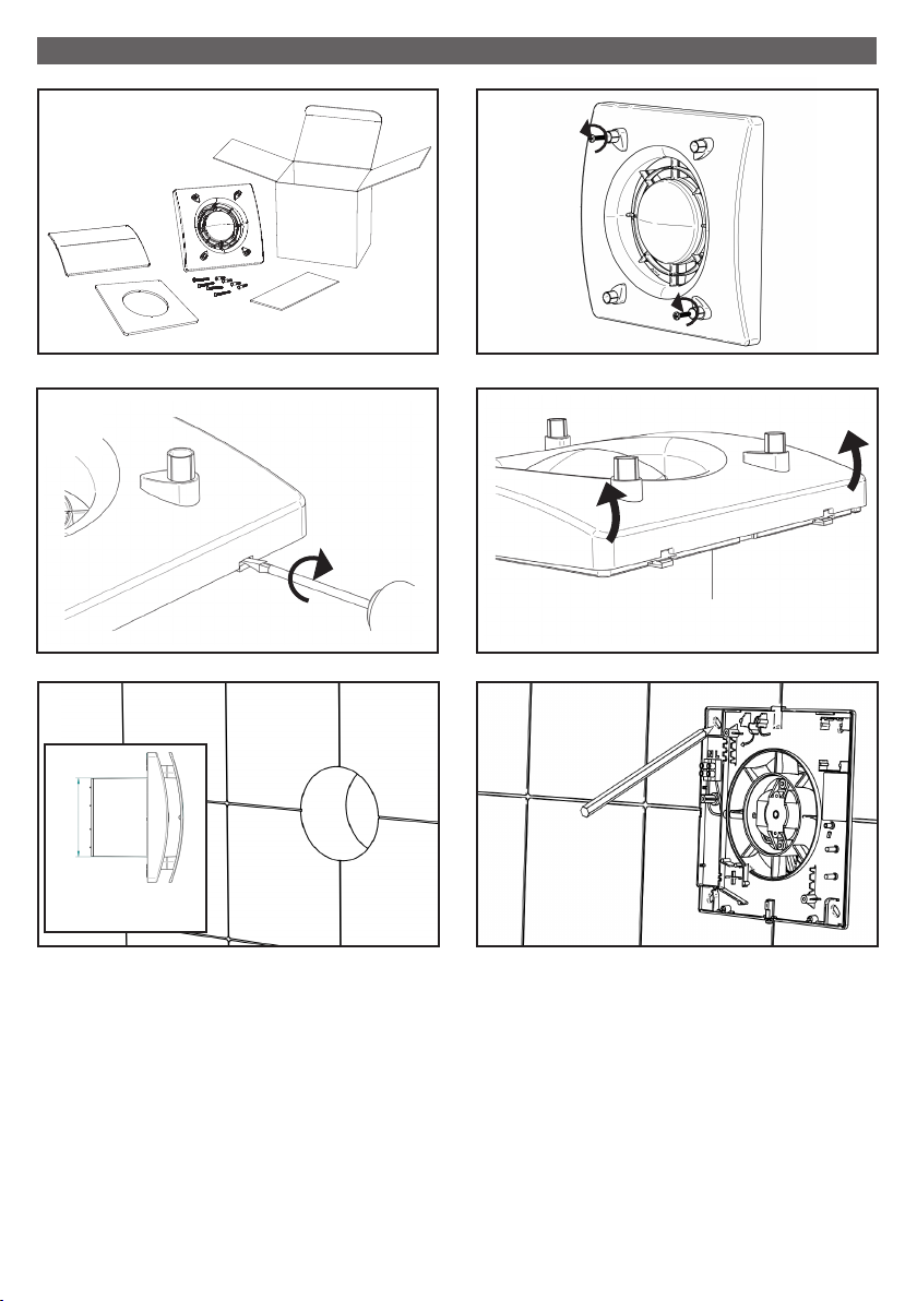
MOUNTING AND ELECTRICAL WIRING
3
5
7
4
6
6
8
Ø
MORI dMEV II = ø99 mm
5
Page 6

SURFACE CABLE
2 X 0,5 ÷ 1,5 mm2
BASE/STD
H03VV-F ; H05VV-F
{
3 X 0,5 ÷ 1,5 mm2
3 X 0,5 ÷ 1,5 mm
T-HT
{
4 X 0,5 ÷ 1 mm2
9A
2
4 x ø 5 mm
10A
12A
11A
d
Ø
Ø10mm
d
Ø
6
13A
Page 7

RECESSED CABLE ENTRY
H03VV-F ; H05VV-F
2 X 0,5 ÷ 1,5 mm2
BASE/STD
{
3 X 0,5 ÷ 1,5 mm2
3 X 0,5 ÷ 1,5 mm
T-HT
{
4 X 0,5 ÷ 1 mm2
9B
2
4 x ø 5 mm
10B
11B
12B 13B
14 15
The ceiling mounting gasket should be sandwiched between the fan and
the ceiling ensuring that it is flat against the ceiling. Included in the box.
For window mounting instruction please see the individual installation
manual.
7
Page 8

16A
N
L
PULL CORD
N
L
PULL CORD
16B
16C
16E
MORI dMEV II T
MORI dMEV II T
MORI dMEV II HT
MORI dMEV II T
16D
Double Pole Switch
MORI dMEV II HT
17A
+
-
TIMER
17B
TIMER
HY
+ higher humidity set point
8
JUMPER
+
-
+
-
18
1 2 3
MORI dMEV II M (ISSUE A & B)
MORI dMEV II T - MORI dMEV II HT
INSTALLATION AIRFLOW
through wall OFF
through wall 6L/s
through wall 8L/s
through wall 13L/s
in room OFF
in room 6L/s
in room 8L/s
in room 13L/s
= Jumper present
Page 9

19
20
CLICK
21
22 23
ON
OFF
9
Page 10

MAINTENANCE / CLEANING
The unit should be cleaned regularly as explained in this leaflet to maintain performance
and warranty cover. Cleaning should be carried out as and when required but please note
intervals between cleaning should not exceed 6 months. The installer should explain this
cleaning regime to the homeowner/occupier and ask the homeowner/occupier to keep a
record of the cleaning done on this leaflet as this will be required to be provided by the
homeowner/occupier to claim against any product failure under warranty.
24
25
26 27
28
10
Page 11

DISPOSAL AND RECYCLING
Information on disposal of units at the end of life.
This product complies with EU Directive 2002/96/EC.
The symbol of the crossed-out dustbin indicates that this product must be
collected separately from other waste at the end of its life. The user must,
therefore, dispose of the product in question at suitable electronic and
electro-technical waste disposal collection centres, or else send the
product back to the retailer when purchasing a new, equivalent type device.
Separate collection of decommissioned equipment for recycling, treatment
and environmentally compatible disposal helps to prevent negative effects
on the environment and on health and promotes the recycling of the
materials that make up the equipment. Improper disposal of the product
by the user may result in administrative sanctions as provided by law.
GUARANTEE
The product is offered with a five year warranty.
First year of warranty covers parts and labour, following this period the warranty covers
replacement parts only based on maintenance having being carried out in accordance
with our literature and terms and conditions of sale.
Proof of purchase, periodic inspection and maintenance will be required in the event of
any warranty claim.
11
Page 12

ErP Directive - Regulations 1253/2014 1254/2014
a) Mark - ELTA FANS ELTA FANS
b) Model -
c) SEC class - E C
c1) SEC warm climates kWh/m2.a -5,4 -11,3
c2) SEC average climates kWh/m2.a -13 -25,7
c3) SEC cold climates kWh/m2.a -26,4 -50,7
Energy label
d) Unit typology - Residenal - unidireconal Residenal - unidireconal
e) Type of drive - mul speed drive mul speed drive
f) Type of Heat Recovery System - absent absent
g) Thermal eciency of heat recovery % N/A N/A
h) Maximum ow rate m3/h 83 83
i) Electric power input at maximum ow rate W 2,6 2,6
j) Sound power level (LWA) dBA 44 44
k) Reference ow rate m3/h 61 61
l) Reference pressure dierence Pa 10 10
m) Specic Power Input (SPI) W/m3/h 0,028 0,028
n1) Control factor - 1 0,65
n2) Control typology - Manual control (no DCV) Local demand control
o1) Maximum internal leakage rate % N/A N/A
o2) Maximum external leakage rate % N/A N/A
p1) Internal mixing rate % N/A N/A
p2) External mixing rate % N/A N/A
q) Visual lter warning - N/A N/A
r) Instrucons to install regulated grilles - check the instrucon booklet check the instrucon booklet
s) Internet address for preassembly/disassembly instrucons - www.eltafans.com www.eltafans.com
t) Airow sensivity to pressure variaons % N/A N/A
u) Indoor/outdoor air ghtness m3/h 52 52
v1) AEC - Annual electricity consumpon - warm climates kWh 0,4 0,2
v2) AEC - Annual electricity consumpon - average climates kWh 0,4 0,2
v3) AEC - Annual electricity consumpon - cold climates kWh 0,4 0,2
w1) AHS - Annual heang saved - warm climates kWh 6,3 11,9
w2) AHS - Annual heang saved - average climates kWh 14 26,2
w3) AHS - Annual heang saved - cold climates kWh 27,3 51,3
- No No
MORI dMEV II T MORI dMEV II HT
12
Page 13

NOTES
13
Page 14

NOTES
14
Page 15

NOTES
15
Page 16

Elta Fans Limited
Building Services
46 Third Avenue
Pensnett Trading Estate
Kingswinford
West Midlands
DY6 7US
United Kingdom
T: +44 (0) 1384 275800
F: +44 (0) 1384 275810
E: bs@eltafans.co.uk
001435 - 05 - 0518
 Loading...