

Page 1

G
Installation manual
CETO100 - Centrifugal fan
Introduction
CETO100 (fig. 1) is a centrifgual fan designed to ensure
air extraction in small/medium-sized rooms such as bathrooms, toilets and kitchens.
Suitable for air discharge through long length ducting.
Wall or ceiling installation, surface or recessed in plasterboard walls (fig.2).
Read this manual carefully before using the product and keep it in a safe place for reference.
This product was constructed up to standard and in compliance with regulations relating to electrical equipment and must be installed by technically qualified personnel.
The manufacturer assumes no responsibility for damage to persons or property resulting from failure to observe the regulations contained in this
booklet.
TECHNICAL SPECIFICATIONS
• Material: High quality, impact and UV-resistant ABS colour RAL 9010
• Design front cover removable for cleaning without the use of tools
• Highly quality forward-curved impeller for high performance and top silence.
• Single phase 2-speed motor with integral thermal protection.
• Motor mounted on ball bearings that guarantee a longer product life cycle (30,000 h) and suitable for cold climates
• The fan is double insulated: no earth connection is required
• Suitable for continuous or intermittent operation
• IPX4 degree of protection
• Power supply 220V to 240V~ 50/60Hz
Airflow
Model
CETO100 28.8/17.3 104/62 251/142 28/17 38/27
(max)
L/s
m3/h
Static pressure
Pa max
Power
W max
Sound pressure
dB(A) @3m
Fig. 1
PRECAUTIONS FOR INSTALLATION, USE AND MAINTENANCE
• The device should not be used for applications other than those specied in this manual.
• After removing the product from its packaging, verify its condition. In case of doubt, contact a qualied technician. Do not leave packaging
within the reach of small children or people with disabilities.
• Do not touch the appliance with wet or damp hands/feet.
• The device is not intended for use by persons (including children) with reduced physical, sensory or mental capacities or those with a lack of
experience and knowledge, unless they have been given supervision or instruction concerning use of the device from a person responsible for
their safety.
Children should be supervised to ensure that they do not play with the device.
• Do not use the product in the presence of inammable vapours, such as alcohol, insecticides, gasoline, etc.
• If any abnormalities in operation are detected, disconnect the device from the mains supply and contact a qualied technician immediately. Use
original spare parts only for repairs.
• The electrical system to which the device is connected must comply with regulations.
• Before connecting the product to the power supply or the power outlet, ensure that:
- the data plate (voltage and frequency) correspond to those of the electrical mains
- the electrical power supply/socket is adequate for maximum device power. If not, contact a qualied technician.
• The device should not be used as an activator for water heaters, stoves, etc., nor should it discharge into hot air/fume vent ducts deriving from
any type of combustion unit. It must expel air outside via its own special duct.
• Operating temperature: 0°C up to +50 °C.
• The device is designed to extract clean air only, i.e. without grease, soot, chemical or corrosive agents, or ammable or explosive mixtures.
• Do not leave the device exposed to atmospheric agents (rain, sun, snow, etc.).
• Do not immerse the device or its parts in water or other liquids.
• Turn off the main switch whenever a malfunction is detected or when cleaning.
• For installation an omnipolar switch should be incorporated in the xed wiring, in accordance with the wiring regulations, to provide a full
disconnection under overvoltage category III conditions (contact opening distance equal to or greater than 3mm).
Page 2

• If the supply cord is damaged, it must be replaced by the manufacturer, its service agent or similarly qualied persons in order to avoid a
hazard.
• Do not obstruct the fan or exhaust grille to ensure optimum air passage.
• Ensure adequate air return into the room in compliance with existing regulations in order to ensure proper device operation.
• If the environment in which the product is installed also houses a fuel-operating device (water heater, methane stove etc., that is not a “sealed
chamber” type), it is essential to ensure adequate air intake, to ensure good combustion and proper equipment operation.
• Install the product so that the impeller is not accessible from the air outlet side as veried by contact with the Test Finger in compliance with
the current safety regulations.
• Ceiling installation
In order to guarantee the IPX4 degree of protection against moisture in case of ceiling installation, use the appropriate ceiling mount kit, which
is not included. Use only the rear entry hole for supply cables. If there is a possibility of condensation along the air discharge duct, provide a
drainage system to prevent condensation from discharging into the environment through the fan.
Attention: do not mount the product on the ceiling without this kit.
• Recessed installation
In case of recessed installation in plasterboard walls, the two brackets included in the packaging must be used.
VERSIONS
STANDARD
The fan is operated using a separate ON/OFF switch or via a light switch (g. 45A).
PULL CORD
The fan is operated using an integrated pull cord switch (g.45B).
WITH TIMER (over-run)
The fan is provided with a timer circuit which is adjustable from aprox. 1 minute to 25 minutes via trimmer (g. 46A).
Operation: connected according to the diagram in gure 45C, after the light is switched on, the fan activates with a delay of max 1.5 seconds.
After the light is switched off, the fan continues to function for a pre-set period of time.
WITH HUMIDISTAT & TIMER
The fan is equipped with a humidity detector, whose threshold is adjustable from 50% to 95% Relative Humidity, and with a timer which is
adjustable from aprox. 1 minute to 25 minutes via corresponding trimmer (g. 46B).
Turn the trimmer HY completely clockwise and the humidistat function is deactivated.
Automatic humidistat operation: connected according to the diagram in gure 45C, when the percentage of Relative Humidity exceeds the preset intervention threshold, the fan starts up automatically. When the percentage of Relative Humidity goes below the threshold, the fan continues
to function for a pre-set period of time.
Operation with switch connection: connected according to the diagram in gure 45C, after the light is switched on, the fan activates with a delay
of aprox. 1.5 seconds. After it is switched off, the fan continues to function for a pre-set period of time.
Operation via pull cord switch (HTC version): connected according to the diagram in gure 45D. By switching on, the fan activates with a delay of
aprox. 1.5 seconds. After switching off, the fan continues to function for a pre-set period of time
Attention: When the relative humidity level is higher than the pre-set threshold, automatic operation with humidistat has priority over manual
operation, or rather the fan cannot be stopped via switch.
STANDARD CONFORMITY
2006/95/EC Low Voltage Directive (LVD)
2004/108/EC Electromagnetic Compatibility (EMC),
in conformity with the following standards:
Electrical Safety
EN60335-1(2008); EN 60335-2-80(2005); EN 60335-2-80/A2(2009)
Electromagnetic Compatibility
EN 55014-1(2006)+A1(2009); EN 55014-2(1997)+A1(2001)+A2(2008)+IS1(2007)
EN 61000-3-2(2006)+A1(2009)+A2(2009); EN 61000-3-3(2008).
2
Page 3
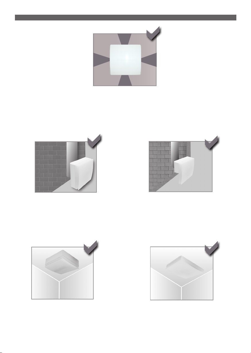
INSTALLATION (Fig.2)
perimetrical exhausting
wall - surface
ceiling - surface (accessory on demand)
wall - recessed
ceiling - recessed
3
Page 4
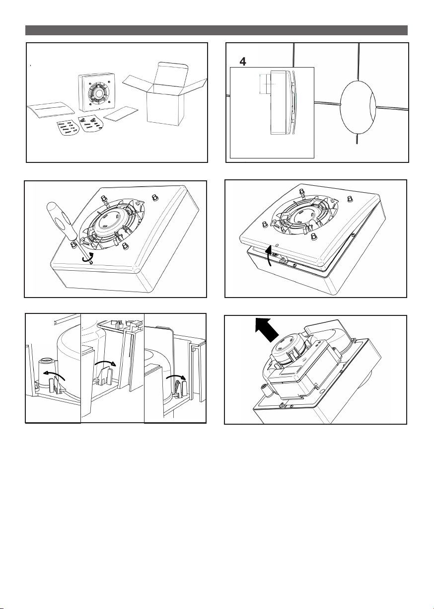
MOUNTING
3
5
7
4
Ø
CETO100 = Ø 96mm
6
8
4
Page 5

SURFACE INSTALLATION
SURFACE CABLE
10A
12A
H03VV-F ; H05VV-F
2 X 0,5 ÷ 1,5 mm2
BASE/STD
{
3 X 0,5 ÷ 1,5 mm2
3 X 0,5 ÷ 1,5 mm
T-HT
{
4 X 0,5 ÷ 1 mm2
3 x Ø 5mm
2
9A
11A
13A
14A
~ 150mm
~ 5mm
5
Page 6

SURFACE INSTALLATION
RECESSED CABLE ENTRY
10B
12B
H03VV-F ; H05VV-F
2 X 0,5 ÷ 1,5 mm2
BASE/STD
{
3 X 0,5 ÷ 1,5 mm2
3 X 0,5 ÷ 1,5 mm
T-HT
{
4 X 0,5 ÷ 1 mm2
3 x Ø 5mm
2
9B
11B
13B
14B
~ 150mm
6
Page 7

15
16
17
19 20
WIRING DIAGRAM: PAGE 17 -
18
21
22
7
Page 8

23
25
RECESSED INSTALLATION
24
RECESSED CABLE ENTRY
H03VV-F ; H05VV-F
2 X 0,5 ÷ 1,5 mm2
BASE/STD
T-HT
27
8
{
3 X 0,5 ÷ 1,5 mm2
3 X 0,5 ÷ 1,5 mm
{
4 X 0,5 ÷ 1 mm2
2
26
9÷40 mm
28
233 mm
225 mm
Page 9

29
30
31
33
35
32
34
~ 150mm
36
9
Page 10

37
38
39
40
WIRING DIAGRAM: PAGE 17 -
41
42 43
10
Page 11

44
ELECTRICAL WIRING
45A
5
CETO100 Vmax
45A
max
CETO100 Vmin
45B
CETO100C Vmax
PULL CORD
NO
5
5
PULL CORD
CETO100C Vmin
11
Page 12

45C
ROSSO-RED-ROUGE-ROJO
CETO100T-HT Vmax
5
CETO100T-HT Vmin
45D
ROSSO-RED-ROUGE-ROT
PULL CORD
CETO100HTC Vmax
5
46A 46B
+
-
ROSSO - RED - ROUGE - ROJO
ROSSO - RED - ROUGE - ROT
PULL CORD
CETO100HTC Vmin
+
-
+
-
HY
TIMER
12
TIMER
Page 13

MAINTENANCE / CLEANING
47 48
49
51
50
13
Page 14

14
Page 15

15
Page 16

DISPOSAL AND RECYCLING
Information on disposal of units at the end of life.
This product complies with EU Directive 2002/96/EC.
The symbol of the crossed-out dustbin indicates that this product
must be collected separately from other waste at the end of its life. The user
must, therefore, dispose of the product in question at suitable
electronic and electro-technical waste disposal collection centres, or else send the product back to the retailer
when purchasing a new, equivalent type device.
Separate collection of decommissioned equipment for
recycling, treatment and environmentally compatible disposal helps to
prevent negative effects on the environment and on health and promotes the recycling of the materials that make up
the equipment.
Improper disposal of the product by the user may result in administrative sanctions as provided by law.
CFI0002E - 01 -0314
Elta Fans Limited
Building Services
46 Third Avenue
Pensnett Trading Estate
Kingswinford
West Midlands
DY6 7US
United Kingdom
T: +44 (0) 1384 275800
F: +44 (0) 1384 275810
E: bs@eltafans.co.uk
 Loading...