

ELT GsmAlarm-420 User Manual
_________________________________________________________________________________
GsmAlarm-420 Software ver. 1.05
GsmAlarm-420 (V1.05)
GSM Alarm and Remote control System
FEATURES
• Integrated GSM module.
• 4 inputs for door, motion, fire sensor connection.
• 3 programmable outputs for remote control.
• Option to switch the protection mode on/off by short free call.
• 5 users are informed on the protected unit.
• 250 users able to control the gate or electromagnetic lock by short free call.
• Info-carrying SMS on the state of each sensor, number of triggers, system mains voltage,
GSM signal strength.
• Option to connect siren.
• Option to connect external mic.
• Remote programming.
• Cheap maintenance.

TABLE OF CONTENTS
_________________________________________________________________________________
GsmAlarm-420 Software ver. 1.05
2
Table of Contents
1. General Information ..................................................................................................................... 1
1.1. Safety Instruction ..................................................................................................................... 1
1.2. Package Content....................................................................................................................... 2
1.3. General Description ................................................................................................................. 3
2. Connectors and LEDs ................................................................................................................... 4
2.1. Inputs Z1-Z5 ............................................................................................................................ 4
2.2. Microphone Connection Contacts ............................................................................................ 5
2.3. Outputs C1 and C2 ................................................................................................................... 5
2.4. Output BELL ........................................................................................................................... 5
2.5. Output AUX ............................................................................................................................. 5
2.6. Contact B+ ............................................................................................................................... 5
2.7. Contacts POWER..................................................................................................................... 5
2.9. Contacts RESET ...................................................................................................................... 5
3. LED Indicators .............................................................................................................................. 6
3.1. SIGNAL: Indicator of Signal Strength and GSM Module Operation Mode ............................. 6
3.2. Z1-Z4: Input Status Indicator ................................................................................................... 6
3.3. MODE: System Operation Mode Indicator .............................................................................. 6
3.4. ALARM: Alarm Mode Indicator ............................................................................................. 6
4. Installation ..................................................................................................................................... 7
4.1. Instruction for Premises Protection Installation ........................................................................ 7
4.2. Instruction for Car Alarm Installation ...................................................................................... 9
4.3. System Operation Set Up ....................................................................................................... 10
5. Programming .............................................................................................................................. 11
5.1. User Number Programming with Standard Mobile Phone ..................................................... 11
5.2. User Number Programming with SMS .................................................................................. 12
5.3. System Parameter Programming with SMS ........................................................................... 14
5.3.1. Protected Zones Z1-Z5 Parameter Programming ............................................................ 14
5.3.1.1. Parameter M ............................................................................................................ 15
5.3.1.2. Parameter A ............................................................................................................ 15
5.3.2. Programming of Output C1, C2, BELL and Common System Parameters E, F, T, U ... 16
5.3.2.1. Output C1, C2 and BELL Operation Mode .............................................................. 17
5.3.2.2. Parameter E : Informing User about Arming and Disarming .................................. 17
5.3.2.3. Parameter F : System Response to Incoming Calls and Number
of Calls in Alarm Mode ............................................................................................ 18
5.3.2.4. Parameter U : Reserve Battery Voltage .................................................................... 18
5.4. SMS Password Change .......................................................................................................... 18
5.5. Programming of the Gate Control Mode ................................................................................ 18
6. Resetting System Parameters to Factory Defaults .................................................................... 19
6.1. Premises Protection Mode Factory Defaults .......................................................................... 19
6.2. Vehicle Protection Mode Factory Defaults ............................................................................ 20
7. System Control ............................................................................................................................ 21
7.1. Arming/Disarming with ON/OFF Switch .............................................................................. 21
7.2. Arming/Disarming Remotely ................................................................................................. 21
7.3. Control Using DTMF and SMS Instructions .......................................................................... 22
8. Warranty ..................................................................................................................................... 24
9. Technical Characteristics ........................................................................................................... 25

GENERAL DESCRIPTION
_________________________________________________________________________________
GsmAlarm-420 Software ver. 1.05
- 1 -
1. GENERAL INFORMATION
1.1. SAFETY INSTRUCTION
Important! Read and strictly follow all safety and operational instructions written in this user
manual, before using GsmAlarm-420 in order to guarantee safety and prevent possible injuries from
possible thermal and electric device failures for you and surrounding people.
Retain all safety and operational instructions for future reference during the whole operation lifetime
of device.
Device has two power supplies:
main and reserve
.
For premises protection:
Main: power transformer: I: 230V 50/60 Hz; II: (16–24)V ~ 1,2 A 50/60Hz;
Reserve: 12 V 1,2 Ah battery.
For car protection:
Main:12 V car battery;
Reserve: 6 V 1,2 Ah battery.
Device GsmAlarm-420 certifies required safety level of LST EN 60950-1:2003
standard.
All power supplies described above and connected to device must satisfy the
safety requirements of LST EN 60950 –1 standard!
External power supply can be connected to AC mains only inside installation
room with automatic 2-pole circuit breaker capable of disconnecting circuit
in the event of short circuit or over-current.
Open circuit breaker must have a gap between connections of more than 3mm
and the disconnection current 5A.
Only a qualified specialist possessing strong knowledge about general safety
requirements and technology of device can perform system installation works and
technical support.
In case of any device performance disorder only qualified specialist can repair it.
There are no parts you can change at place in the device.
ATTENTION!
EXPLOSION POSSIBLE USING WRONG KIND BATTERIES - NOT
RECOMMENDED BY MANUFACTURER.
DO NOT SWITCH POLES OF BATTERY BY ACCIDENT.
DO NOT SHORT CIRCUIT BATTERY POLES.
MAINTENANCE PERSONNEL WARNING!
TWO POLES OF AC ELECTRIC POWER SUPPLY.
POWER TRANSFORMER CUT-OUT IN NEUTRAL CABLE!
Disconnect device from AC power and reserve battery before performing any
installation or maintenance work.
It is forbidden to perform any device installation or maintenance work during
lightning!
GENERAL DESCRIPTION
_________________________________________________________________________________
GsmAlarm-420 Software ver. 1.05
- 2 -
Remote control and monitoring device GsmAlarm-420 has built-in radio transmitter operating on
GSM900 and GSM1800 networks.
Do not use the device where it can cause interferences and danger.
Do not arrange the device close to medical equipment and appliances.
Do not use the device in explosive environment.
Device is not resistant to moisture, chemical materials or mechanical damage.
Don’t attempt to personally repair the system.
System label is on the bottom side of the device.
This symbol on the product or on its packaging means that your electrical and electronic
equipment should be disposed at the end of life separately from your household wastes.
There are separate collection systems for recycling in EU. For more information, please
contact the local authority or the dealer where you purchased the product.
The device compliance to RoHS Directive.
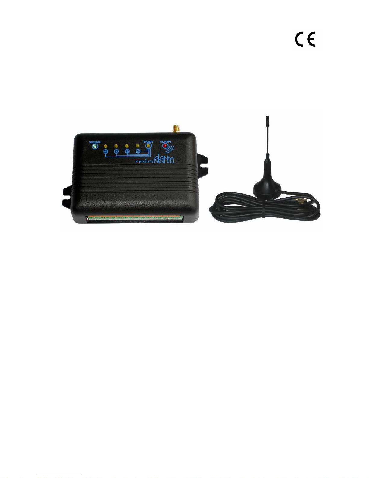
1.2. PACKAGE CONTENT
GsmAlarm-420 main board ........................................................................... Qnty 1
GSM antenna with magnetic fix and 2 m lead cable ...................................... Qnty 1
Microphone with 1,5 m lead cable ................................................................. Qnty 1
Load resistors 2,2kΩ ±5% ............................................................................. Qnty 6
Clamping cable for accumulator connection .................................................. Qnty 1
User‘s manual ................................................................................................ Qnty 1

GENERAL DESCRIPTION
_________________________________________________________________________________
GsmAlarm-420 Software ver. 1.05
- 3 -
1.3. GENERAL DESCRIPTION
Four zone control and monitoring device GsmAlarm-420 can be used for protection of cars, boats,
houses, apartments, garages, and cottages. In the case of a breach of the protected zone and
depending on the programmed system operation algorithm, GsmAlarm-420 switches on the siren ,
calls and sends SMS messages to five users. After answering the call, a user can remotely control the
system by means of his phone keypad (DTMF tones) (e.g., stop a car engine), can listen to what is
going on in the room, request an SMS with detailed information on the state and the number of
activations of each controlled zone.
GsmAlarm-420 has 2 (3, if a siren is not used) programmable outputs, intended for remote control of
different devices. A user can turn on/off heating, ventilation or lighting systems, etc., via a mobile
phone just by typing a relevant code or sending SMS to the control device.
For user’s convenience, the system can indicate entrance/exit with an audio signal, if the miniature
sound signalization element is connected to system.
A user will receive an SMS message, if GSM connection was lost for over 30 seconds. The message
is sent only when the protection mode is turned on.
The device suites perfectly for remote control of automated gates, fences and electromagnetic door
locks. In order to open a gate, a user calls the number of GsmAlarm-420. Then GsmAlarm-420
verifies that the caller’s number is in the list of the programmed user numbers and in case of positive
confirmation switches on the gate control device and automatically terminates the call. Up to 250
users can control a gate.
The system answers only to calls from the pre-programmed numbers. If the system receives a call
from an alien number, the call is immediately terminated and an SMS is sent the user, indicating the
caller's phone number. SMS messages are also sent to users in case of loss and restoration of power.
Operation of the alarm can be check by a short call to the GsmAlarm-420 number. If GsmAlarm-420
is operative, the caller will get a short confirmation call.
All GsmAlarm-420 parameters are programmable remotely by means of SMS messages with
respective content and the password.
CONNECTORS AND LEDS
_________________________________________________________________________________
GsmAlarm-420 Software ver. 1.05
- 4 -
2.2k
+3V
GND
Z
PROCESSOR
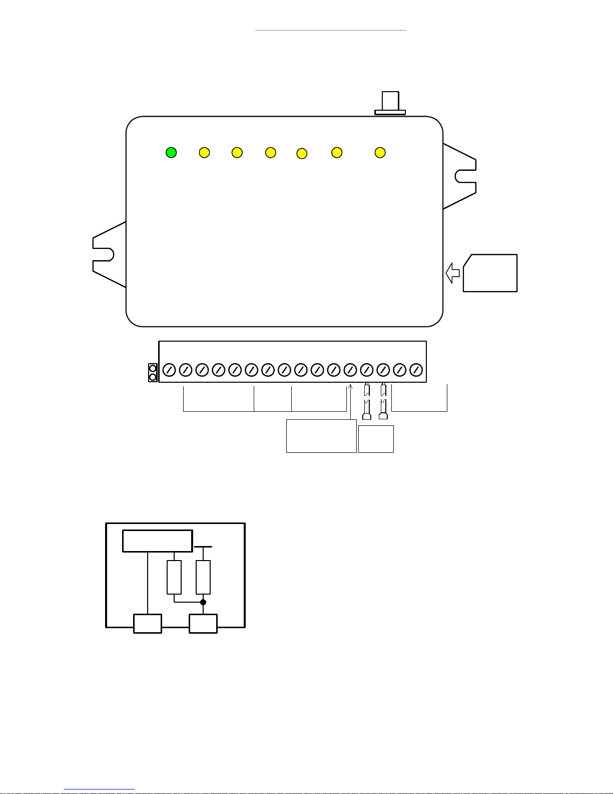
2. CONNECTORS AND LEDs
SIGNAL Z1 Z2 Z3 Z4 MODE ALARM
RESET
Contact
Microphone
Input
L E D Indicators
G S M A L A R M - 4 2 0
Sensor Inputs
" - "
SIM CARD
Programmable
Outputs
Power Supply
Input AC/DC,
16-24V
DC Supply Output
(12V or 6V)
GND Z1 Z2 Z3 Z4 Z5 M- M+ C1 C2
BELL
AUXB+GND
POWER
ANTENNA CONNECTOR
Red
-
+
Blue
Backup
Battery
Input
GsmAlarm-420 connection contacts and LED indicators
2.1. INPUTS Z1-Z5
Inputs Z1-Z5 are used to connect sensors of protected zones. The
inputs can operate in a “loaded input” mode or in a “zero-one”
mode (see Ch. 5.3.1.2). The “loaded input” mode is
recommended to be used for protection of premises. In this case
all the inputs have to be loaded with 2,2kΩ resistors. The system
becomes triggered both when the monitored input circuit is
broken as well as when it is short-circuited.
In the second case the system is triggered after breaking or short-
circuiting of the monitored input circuit (depending on the
programmed "active" level).
Equivalent diagram of input
Input Z5 is used to arm/disarm the system. System can be armed by applying active level to Z5. After
the delay time passes, the system starts checking the monitored inputs; in the case of alarm it
activates the siren, calls and sends SMSs. After Z5 level is changed, the system is disarmed and
responds to no zone changes (except when the monitored zone is operative 24 hours per day).
CONNECTORS AND LEDS
_________________________________________________________________________________
GsmAlarm-420 Software ver. 1.05
- 5 -
2.2. MICROPHONE CONNECTION CONTACTS M- M+
Contacts M- and M+ are used to connect external microphone. Connect black/ white wire to contact
M+, black to M-. Try to install microphone as far as possible from GSM antenna. If wire of the
microphone is long (over 2 m), it is recommended to use shielded twisted pair cable. Connect shield
to GND contact.
Microphone is switched on by DTMF instruction 66* in the conversation mode (see Ch. 7.3).
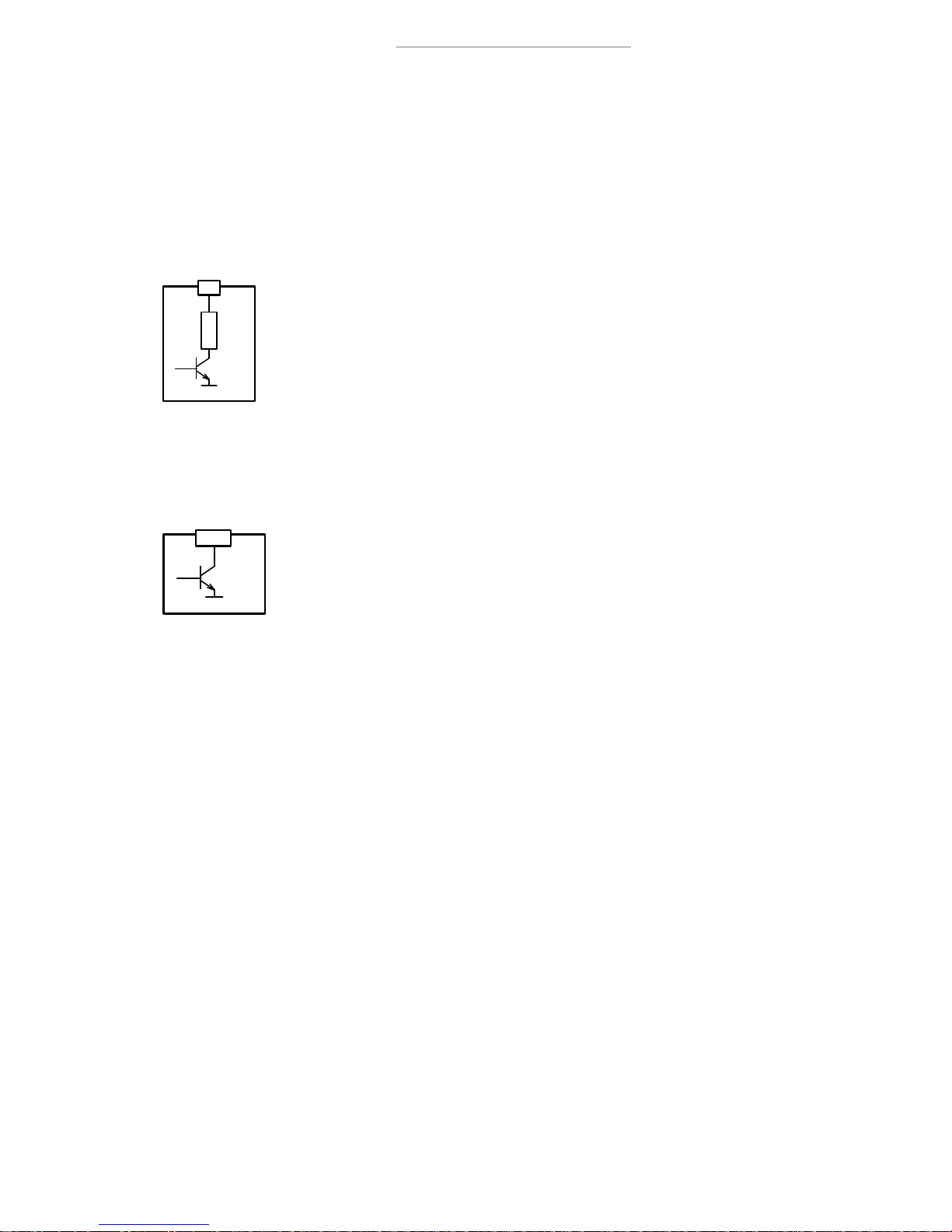
2.3. OUTPUTS C1 & C2
Programmable outputs C1 and C2 are used to connect remotely controlled devices.
Relays with 12V operation voltage and current not exceeding 150 mA max, are
recommended for device control.
Output operation modes are described in Ch. 5.3.2.1
C1-C4 equivalent diagram
2.4. OUTPUT BELL
The BELL output is used to connect audio siren or extra-commutated device (see
Ch. 4.1 and 4.2).
Commutated current may reach 0.6 A max.
Equivalent diagram of BELL OUTPUT
2.5. OUTPUT AUX
AUX output is used to supply power external devices (fire, motion sensors) and is short-circuitprotected. This output has voltage +13.7 V or +6.8V (depending on the system parameter U, see Ch.
5.3.2 and 6.2). Load current is 1 A max.
2.6. CONTACT B+
“+” terminal of reserve battery is connected to contact B+. Max capacity of the battery is 1.2 Ah.
12 V battery is used in the premises protection mode.
It is recommended to use 6 V battery for car protection. In this case switch GsmAlarm-420 to 6 V
mode (see par. 5.3.2 and 6.2).
2.7. CONTACTS POWER
Input POWER is used to connect secondary winding of power supply transformer with voltage
between 16V and 24V (or 12V DC in car protection mode).
2.8. CONTACTS RESET
RESET contacts are used to restore factory default parameters (see. Ch. 6).
C
33
GND
GND
BELL
CONNECTORS AND LEDS
_________________________________________________________________________________
GsmAlarm-420 Software ver. 1.05
- 6 -
3. LED INDICATORS
Lihgt indicators facilitate quick adjustment and troubleshooting of the system during installation.
3.1. SIGNAL: INDICATOR OF SIGNAL STRENGTH AND GSM MODULE OPERATION
MODE
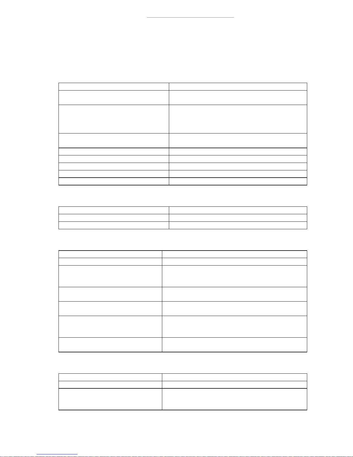
Indicator state Explanation
Out. GSM module is not in use. No power supply or
system failure.
Continuously On.
There is no GSM operator network registration.
Possible causes: SIM card PIN code request is not
deactivated, antenna not connected or poor network
connection quality.
Blinking more frequently than once a
second.
GSM module is in use: outgoing call or SMS is
being sent.
Blinks 5 times, short break after. Very good signal.
Blinks 4 times, short break after. Good signal.
Blinks 3 times, short break after. Satisfactory connection.
Blinks 2 times, short break after. Weak connection.
Blinks once, short break after. Poor connection.
3.2. Z1-Z4: INPUT STATUS INDICATOR
Indicator state Explanation
Out. Input is not triggered
Continuously On. Input is triggered
3.3. MODE: SYSTEM OPERATION MODE INDICATOR
Indicator state Explanation
Out. No power supply or system failure.
Continuously On.
System is operative, disarmed, no zone sensors have
been triggered.
On with short breaks. System is operative, disarmed, but one or more zone
sensors have been triggered.
Blinking with low frequency (once in
2-3 sec.).
System is operating in armed mode.
Blinking more frequently than once a
second.
System is in alarm state, siren is active, call or SMS is
sent. If SMS is sent, indicator blinks a little bit slower
(about twice a second).
Blinking very rapidly for 2-3 sec.
SMS instruction or DTMF command receipt
confirmation.
3.4. ALARM: ALARM MODE INDICATOR
Indicator state Explanation
Blinks at a permanent rate. System is in alarm state, call is made or SMS sent.
Blinks twice every 2-3 seconds. ALRNR1 number has not been programmed. In order
GsmAlarm-420 could make calls, this number need to
be programmed!
INSTALLATION
_________________________________________________________________________________
GsmAlarm-420 Software ver. 1.05
- 7 -
4. INSTALLATION
According to manufacturer recommendations, hire qualified security system specialist (or company)
to perform system installation works. Self-dependent installation of the system can be performed
only if person possess basic knowledge in electricity and electronics, otherwise device might be
irrecoverably damaged.
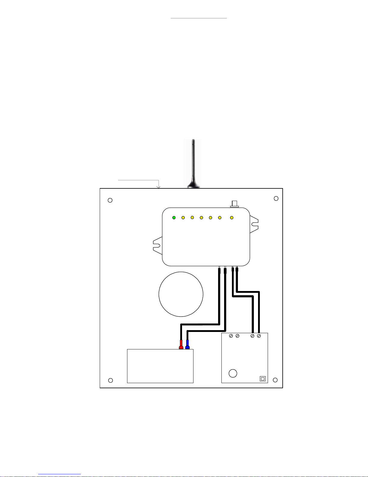
4.1. INSTRUCTION FOR PREMISES PROTECTION INSTALLATION
System should be assembled in metal housing 7TRP20 as recommended. Antenna is fixed on the top
of outer side of metal housing.
Cable
Hole
Housing
Fixture
Holes
4 x 5 mm
Metal Housing (7/TRP20)
SIGNAL
Z1 Z2 Z3 Z4
MODE ALARM
G S M A L A R M - 4 2 0
ANTENNA CONNECTOR
RED
BLUE
RESERVE
BATT ERY
AC 12V 1.2Ah
(CT1.2-12)
-
+
SAUGIKLIS
POWER SUPPLY
TRANSFORMER
T 0.16A
LSTEN 60950
(TRP 20/01)
AC 18VAC 230V
POWERB+ G ND
Layout of system elements in 7/TRP20 type housing
Use double isolated cable 3x0,75 mm
2
for 230V power supply. Circuit breaker or other surge
protection device should be installed in the 230V power line.
 Loading...