

ELT GsmAlarm-300 User Manual
GSM resender_______________ GsmAlarm-300
1
GsmAla rm-30 0
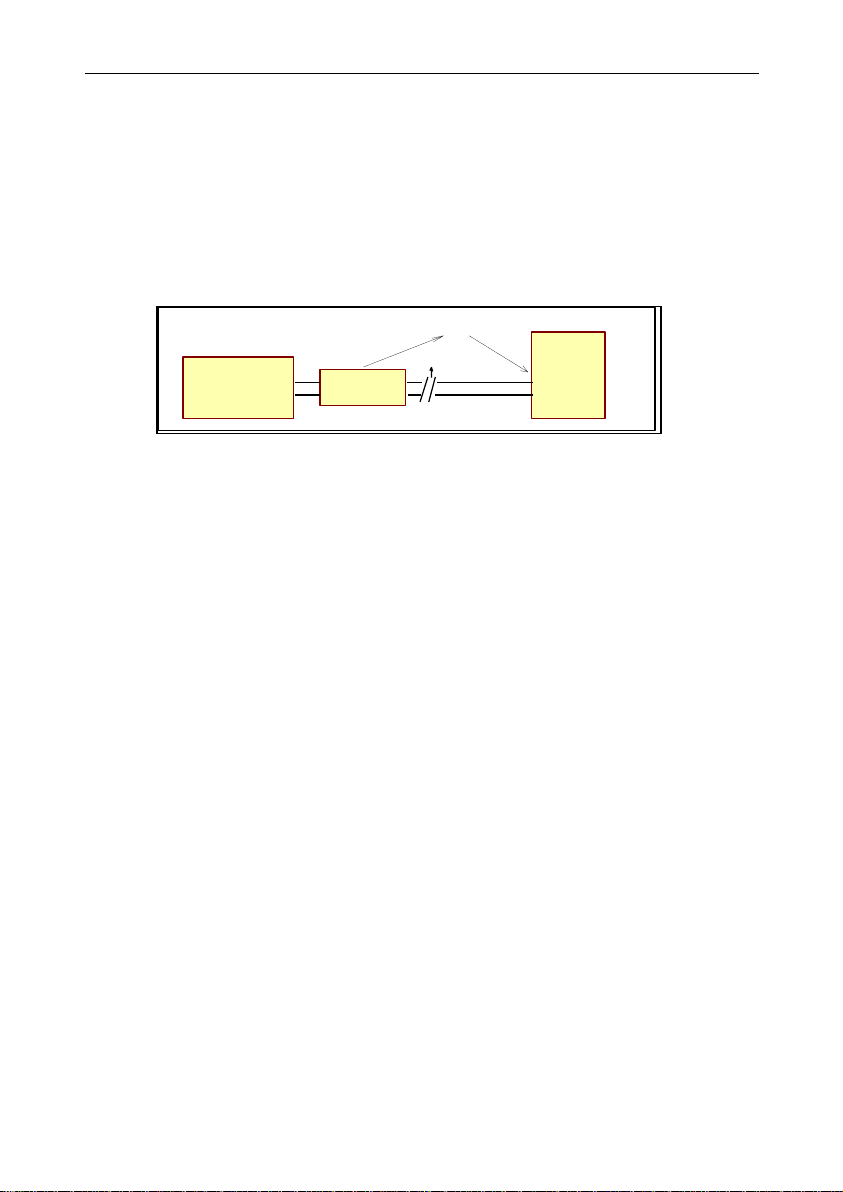
Central
Station
PSTN line
Alarm System
an d
Transmitter
GSM Ne twork
Phone
Line Test
Switch
to GSM
1. GENERAL DESCRIPTION
GsmAlarm-300 provides for reliable double-sided security system communication with the central
station through GSM network.
In the case of wire telephone line failure, GsmAlarm-300 automatically switches the security system
telephone output to the integrated GSM module and the data is relayed to the security panel through
GSM network.
GsmAlarm-300 may be used with any types of security systems, maintaining audible data transfering
protocols: FSK (10 to 300 bauds), DTMF etc.
GsmAlarm-300 is operable in any GSM network of 900/1800 MHz.
GsmAlarm-300 may have up to 4 users. Users may call the GsmAlarm-300 number and control the
system from their phones using DTMF instructions as follows:
connect to the GSM service provider's operator and learn balance of the SIM card account;
ask for SMS, carrying programmed numbers of the users, SMS center and GSM operator's
Caling user is identified by his phone number. If the call comes not from the user's phone, the call is
immediately cancelled. In order to check system operation, user shall briefly call GsmAlarm number.
GsmAlarm-300 within 10-20 seconds answers the caller with a brief ringer tone.
All the GsmAlarm-300 user numbers, SMS center number and brief information number are
programmed by a single SMS with an 8-character password in the beginning of such SMS.
GsmAlarm-300 has a GSM communication failure alarm output as well as a wire line (PSTN) failure
alarm output.
GsmAlarm-300 is very easy to install. State of the device may be quickly evaluated using indication of 4
LEDs.
____________________________________________________________________________________
information;
ask for SMS, carrying information about GsmAlarm-300 communication quality and power
source voltage.

GSM resender_______________ GsmAlarm-300
2
LINECENT
GSM Antenna
Tel.
Line Ground
SIM
Card
GsmAlarm-300
Dual Band Module
+12V GND
POWER
Supply
10.5 ... 15V
+
-
Z2Z1
Reserved
Contacts
GSM 900/1800
Dialler
MODEM MOD E READY LINE
Reader
Visual indicators (LEDs)
Connector
To
In
C2C3
GSM
Fail
PSTN
Fail
2. INSTALLATION
2.1 CABLING AND CONNECTING
2.1.1. Connect antenna to GSM module. Antenna shall be positioned as far from the GsmAlarm-
2.1.2. Insert a SIM card with PIN code OFF.
2.1.3. Connect the CENT contacts to the security centrale telephone line input. During testing,
2.1.4. Connect the contacts +12V and GND to the protection system power source.
2.1.5. Contacts LINE are used to connect the wire telephone line. The telephone line is advised to
2.1.6. The contact C2 (PSTN Fail) - MOSFET "open drain" output - is used to warn about the
2.1.7. The contact C3 (GSM Fail) – MOSFET "open drain" output - is used to warn about GSM
2.1.8. Reserve contacts Z1 and Z2 inside the GsmAlarm-300 module are free and may be used to
300 module as possible. No winded antenna cable is recommended to be left near the
GsmAlarm-300.
parallel ordinary phone device with tone dial may be connected.
connect later - in the end of adjustment.
telephone line (PSTN) failure. This output is activated (connected with the ground wire
GND) in the case of telephone line failure after 15 seconds.
communication failure. This output is activated (connected with the ground wire GND) in the
case of GSM communication failure after 15 seconds.
connect additional wires (e.g. tamper circuitry).
____________________________________________________________________________________
 Loading...