


Gas 4.0 module
Preliminary
Installation instructions
IL42-5015C
INTRODUCTION
The gas module is designed for use with most residential diaphragm gas meters. Modules for residential meters are available in
three distinct types:
• Type A: American Meter Company products
• Type R & R415: Rockwell, Equimeter, Invensys®
• Type S: Sprague, Schlumberger, Actaris, Metris®
TOOLS, EQUIPMENT AND MATERIALS
All or some of the following items may be needed in order to install the module, depending upon the type of meter/index and the
condition of the old index cover and gaskets:
• Gas module
• Connexo FieldSense Installer
• Index screws (2 each)
• Meter mounting bolts (3 or 4 each, depending upon the meter type, supplied with the module)
• Index cover (if old one is not reusable)
• Index cover gasket (supplied with the module)
• Putty knife or scraper to remove old gaskets
• #2 Phillips screwdriver
• Awl to remove existing tamper seals
• Tamper seals (2 each, supplied with the module)
• Pressure compensation factor value, if needed (obtain from Honeywell Smart Energy)
PREPARATION
Before removing the existing index and index cover, make sure that the module style is compatible with the meter style.
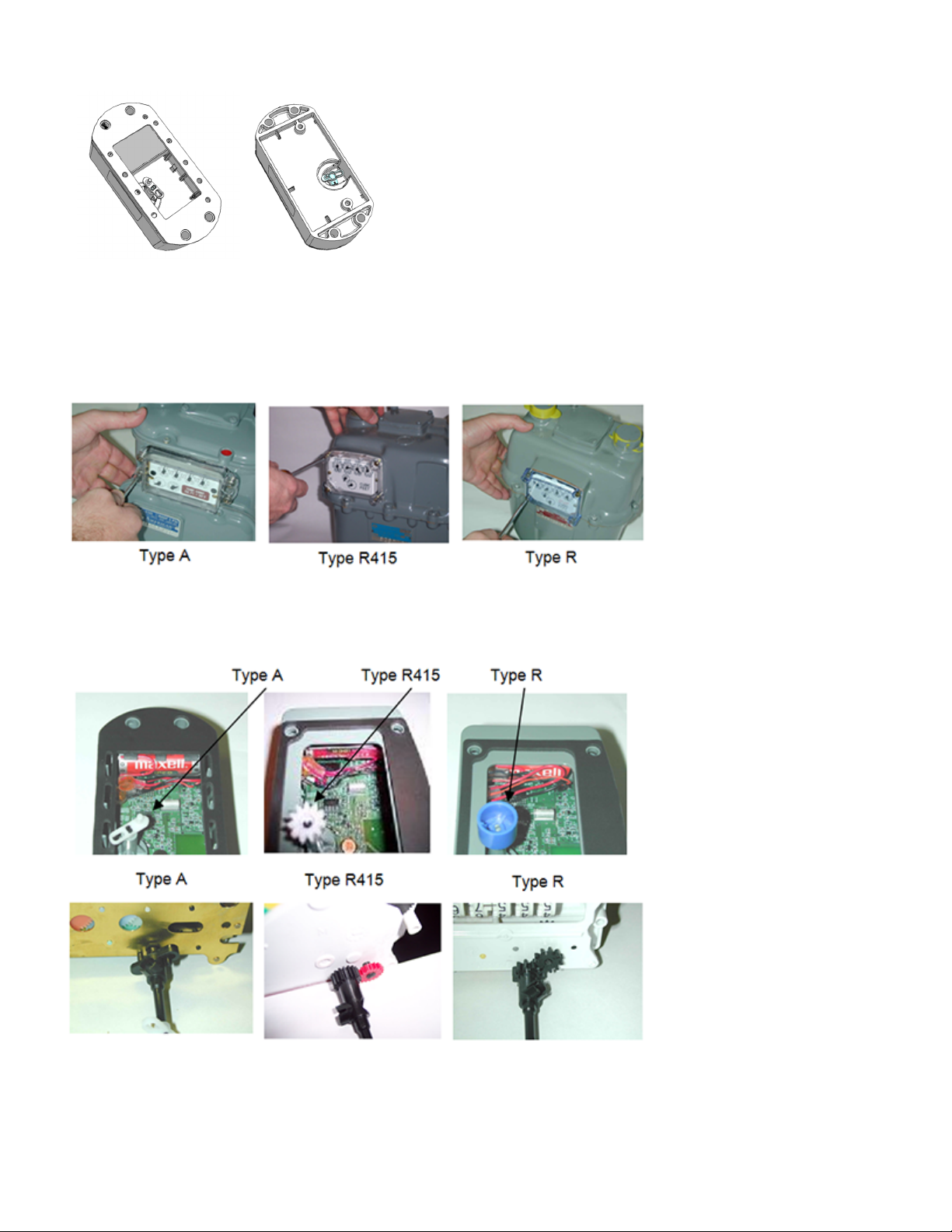
Figure 1. Gas module for Type A index
Battery side
Front side
Preliminary
INSTALLING THE INDEX
1 Remove the existing index cover and index (or module) from the meter. Use an awl to remove the existing tamper seals.
2 Clean any debris from the index and cover.
3 Using a scraper or putty knife, remove the gasket and any adhesive material from the meter.
4 Align the index wriggler with the module wriggler (battery side), as shown below.
Type A
Type R415
Type R

5 Attach the index to the module using the appropriate index screws. Do not over tighten the screws.
CAUTION
!
Tamper seals
Meter mounting
bolts
Index cover
Index screws
Index
assembly
Gas
module
Meter adapter
6/32-inch
screw
Gears meshed
correctly
Preliminary
CHECKING MECHANICAL OPERATION
This procedure will make sure the attached index rotates freely and without resistance.
1 Rotate the index drive dial clockwise 3 times.
2 If the index drive dial turns easily, rotate the drive dial counterclockwise 3 times to remove the counts or subcounts from the
mechanical index. If it does not turn easily, unscrew the index/module assembly & repeat Step 4 in “Installing the index.”
3 Make sure that the gasket material on the index cover is free of rips or tears. If the gasket cover is ripped or torn, remove the
damaged gasket and replace it with a new gasket.
Subcounts added to the electronic index during this procedure will be cleared when the index reading is programmed into the
module.
MOUNTING THE MODULE/INDEX ASSEMBLY
Before mounting the assembly, be sure to have a screwdriver, index cover, and gasket within easy reach.
It is important that the wriggler on the module is correctly engaged onto the meter. If it is not, it could produce an erroneous
indication during utility leak test procedures that monitor drive dial (proving dial) movement. Incorrectly engaged wrigglers
can also cause meter damage. It is important that the following procedure is performed correctly.
1 For Rockwell 415 modules only: Install the meter adapter using the two 6/32-inch screws supplied in the assembly. Make sure
the gears on the adapter & meter are properly meshed.
2 Visually align the module wriggler with the meter wriggler or meter adapter (drive dog). If the wriggler cannot be put in a
fixed position, position it correctly by rotating the drive dial with your finger.
3 Mate the module wriggler with the meter wriggler or meter adapter (drive dog) and hold the mated assembly against the
meter.

4 While holding the assembly against the meter, gently try to turn the drive wheel clockwise and then counterclockwise.
Preliminary
- If the drive wheel meets resistance in both directions, it is properly mated. Continue withStep 5.
- If it meets no resistance in either direction & can freely rotate 360 degrees, then make sure the meter is completely free
of old gasket material then forcefully press the module on to the meter. Repeat Step 4. If the unit still doesn’t correctly
engage with the meter, return the unit to Honeywell Smart Energy.
5 While holding the module firmly in place so that you don’t lose wriggler alignment, place the index cover & cover gasket
onto the module/index assembly. Make sure the index cover is properly positioned with its vent holes at the bottom.
6 Using the appropriate mounting bolts, screw the module/index/cover assembly to the meter and tighten the bolts using a
torque driver. Set the torque driver to 20 in-lbs (± 4 in-lbs tolerance) to secure the assembly to the meter.
7 Install the tamper seals into the index cover receptacles.
PROGRAMMING THE MODULE
Although modules may contain default or utility-specified values that are programmed during manufacturing it is important to
program certain data after the module has been installed in the field. Programming should be performed even if the index is set
to 0000. Follow the instructions in the Connexo FieldSense Installer documentation. When prompted to hold a magnet on the
RTM unit, see for the location.

FCC & Innovation, Science and Economic Development Canada compliance
Preliminary
The radio module is inserted into the housing of the device at manufacture. It has no user serviceable parts.
User Information (Part 15.105): This equipment has been tested and found to comply with the limits for a Class B digital device, pursuant to part 15
of the FCC Rules. These limits are designed to provide reasonable protection against harmful interference in a residential installation. This
equipment generates, uses and can radiate radio frequency energy and, if not installed and used in accordance with the instructions, may
cause harmful interference to radio communications. However, there is no guarantee that interference will not occur in a particular installation.
If this equipment does cause harmful interference to radio or television reception, which can be determined by turning the equipment off and
on, the user is encouraged to try to correct the interference by one or more of the following measures:
• reorient or relocate the receiving antenna
• increase the separation between the equipment and the receiver
• connect the equipment into an outlet on a circuit different from that to which the receiver is connected
• consult the dealer or an experienced radio/TV technician for help
If you experience trouble with this equipment, please use the Return Material Request (RMR) feature available at the Online Customer Services
at www.elstersolutions.com. Do not attempt to repair this equipment itself unless you are replacing the entire module.
Compliance Statement (FCC Part 15.19 and ISED Canada): This device complies with Part 15 of the FCC Rules and with ISED Canada license-exempt RSS
standard(s). Operation is subject to the following two conditions: 1) This device may not cause harmful interference, and 2) This device must
accept any interference received, including interference that may cause undesired operation.
Énoncé de Conformité: Cet appareil est conforme à la Partie 15 des règles de la FCC et aux CNR d'ISED Canada applicables aux appareils radio
exempts de licence. L'utilisation de cet appareil est soumise aux deux conditions suivantes : (1) Cet appareil ne doit pas provoquer
d'interférences nocives et (2) cet appareil doit accepter toutes les interférences reçues notamment celles pouvant provoquer un
fonctionnement intempestif de l'appareil.
Warning (Part 15.21): Changes or modifications not expressly approved by Honeywell could void the user's authority to operate the equipment.
RF Radiation Safety Guidelines: This equipment complies with FCC radiation exposure limits set forth for an uncontrolled environment. This
equipment should be installed and operated to provide a separation distance of at least 28 cm from all persons.
Directives de Sécurité de Radiofréquence: Cet équipement est conforme aux limites d'exposition aux radiations définies par la Commission Fédéral des
Communications (FCC) pour un environnement non contrôlé. Cet équipement doit être installé et utilisé à une distance d'au moins 28 cm de
séparation de toutes personnes.
Collocation Statement: This transmitter must not be co-located or operating in conjunction with any other antenna or transmitter.
Déclaration de Co-localisation: Cet émetteur ne doit pas être co-localisé ou opérant en conjonction avec aucune autre antenne ou transmetteur.
ISED Canada ICES-003 Compliance Label: CAN ICES-3 (B)/NMB-3(B)
Disposal information
This product contains electronics components which should be disposed of in accordance with applicable regulations.

NOTES:
Preliminary
DISCLAIMER OF WARRANTIES AND LIMITATIONS OF LIABILITY
There are no understandings, agreements, representations, or warranties either express or implied, including warranties of merchantability or fitness for a particular
purpose, other than those specifically set out by any existing contract between the parties. Any such contract states the entire obligation of the seller. The contents of
this document shall not become part of or modify any prior existing agreement, commitment, or relationship.
The information, recommendations, descriptions, and safety notices in this document are based on Elster Solutions, LLC experience and judgment with respect to
operation and maintenance of the described product. This information should not be considered as all-inclusive or covering all contingencies. If further information is
required, Elster Solutions, LLC should be consulted.
No warranties, either expressed or implied, including warranties of fitness for a particular purpose or merchantability, or warranties arising from the course of dealing or
usage of trade, are made regarding the information, recommendations, descriptions, warnings, and cautions contained herein.
In no event will Elster Solutions, LLC be responsible to the user in contract, in tort (including negligence), strict liability or otherwise for any special, indirect, incidental, or
consequential damage or loss whatsoever, including but not limited to: damage or loss of use of equipment, cost of capital, loss of profits or revenues, or claims against
the user by its customers resulting from the use of the information, recommendations, descriptions, and safety notices contained herein.
© 2019 by Honeywell International Inc. All rights reserved.
Honeywell Smart Energy Americas
Raleigh, North Carolina
Technical support: 800 338 5251
 Loading...