

Page 1
October 2005 IL42-5002A
Water Module Installation Instructions
General
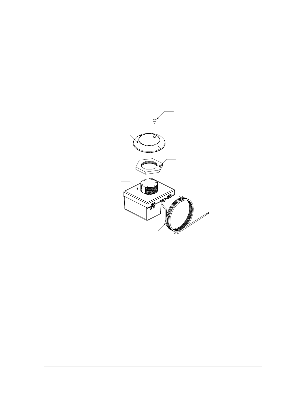
This leaflet contains instructions for Elster's water meter module (see Figure 1) for use on
water meters to provide readings to the EnergyAxis System. For proper installation and
IL42-5002A
maximum life of the modules, use the following procedures. All modules are programmed
and sealed at the factory before shipment.
Familiarize yourself with the location and identification of the terminals on the water meter
register before any installation procedure.
Vandal clip
Cap
Spacer
Water module
Cable
Figure 1. EnergyAxis water meter module
Installation
Direct (Integral) Mounting
The water module is shipped pre-wired and attached to a new water meter. Install the water
meter with the EnergyAxis water module as you would any other water meter.
Pit Applications
The water module is shipped pre-wired to the new water meter. However, it is necessary to
mount the water module to the pit cover. The water module is designed to fit standard
7
(1-
/8 inch diameter) holes in pit covers.
1. Unscrew the cap from the water module. The dome-like cap is fitted to a threaded
cylinder on the top of the module.
2. Adjust the spacer nut as necessary to account for the thickness of the pit cover,
leaving the threaded cylinder protruding above the cover to screw the cap on.
3. Insert the water module's threaded cylinder through the pit cover hole from the
inside of the cover.
1
Page 2
IL42-5002A October 2005
4. Screw the cap onto threaded cylinder. This will secure the water module to the pit
cover.
5. Insert the vandal clip into the cap. It may be necessary to twist the water module
cap slightly to make sure the vandal clip is flush with the cap.
Composite pit covers do not require a hole in the cover. These covers have a shelf on the
inside of the cover for water AMR modules. If you are using composite pit covers, slide the
EnergyAxis water module through the slot on the shelf.
Remote Connections
The water module is shipped along with an enclosure housing. The enclosure housing must
be installed, and then the water module cable must be connected to the water meter
register.
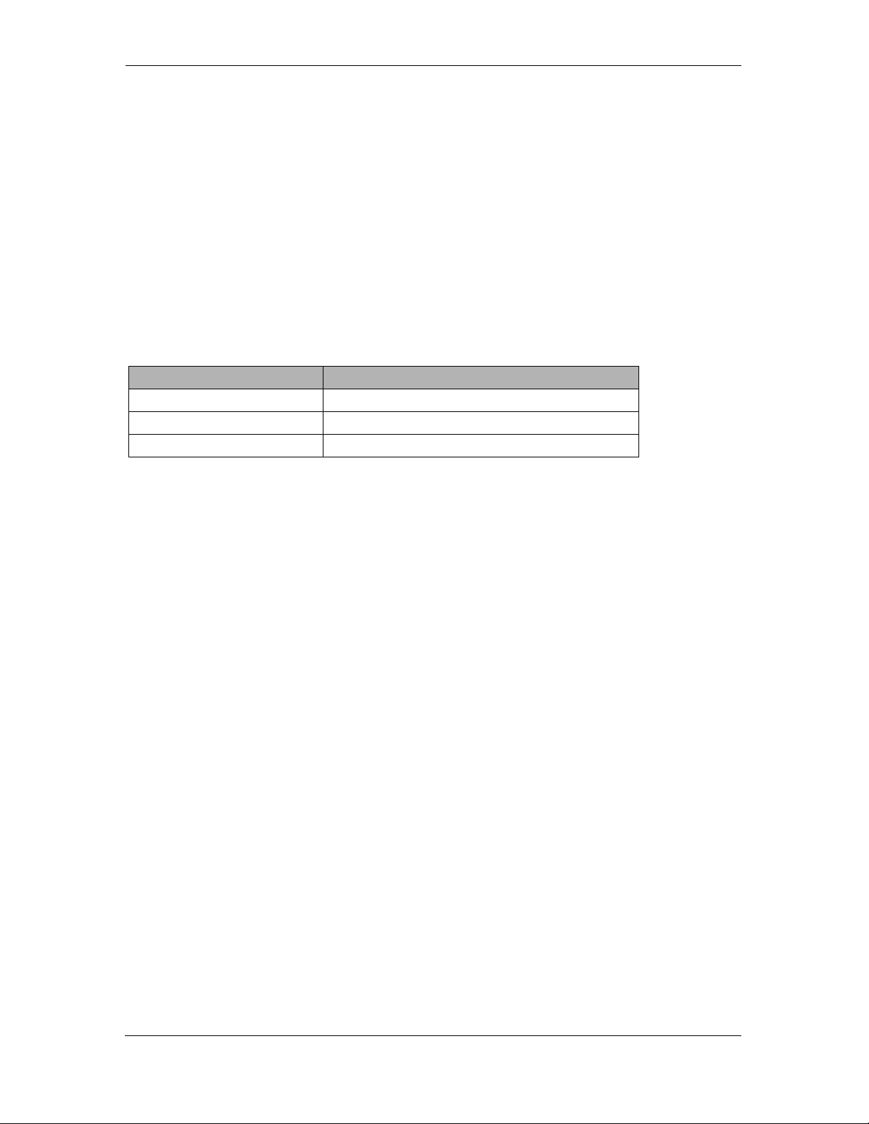
The EnergyAxis water module register connections are as follows:
Te r m i na l c ol or Function
Black Power
Red Data
Bare Common
1. There is a label temporarily placed on the water module. Before placing the water
module inside the enclosure housing, remove this label and place it on a visible area
of the enclosure housing.
2. Place the module inside of the enclosure housing (Elster style number 1C11748H01)
provided with the module. Keep the threaded cylindrical portion of the water
module pointing up and slide the module into the enclosure. The enclosure housing
should be held with the arrow on the top of the housing pointing up while the
module is inserted.
3. With the module secured within the enclosure housing, mount the assembly using
the mounting bosses that are on the sides of the housing. Screws are not included
and should be provided by the utility. It is preferable to mount the housing outside
and above ground; otherwise, mount the housing as high as possible.
4. Connect the black wire to the terminal on the water meter register identified as
DATA. Typically, this connection is done by placing the wire under the screw
terminal and tightening down securely. See the product information for your water
meter register for more information.
5. Connect the red wire to the terminal on the water meter register identified as
POWER. Typically, this connection is done by placing the wire under the screw
terminal and tightening down securely. See the product information for your water
meter register for more information.
6. Connect the bare wire to the terminal on the water meter register identified as
COMMON. Typically, this connection is done by placing the wire under the screw
terminal and tightening down securely. See the product information for your water
meter register for more information.
7. If the standard 6-foot cable is not sufficient, splice the cable using a weatherproof
gel cap (for example, 3M style number 314 IDC) to provide greater length. The total
cable length should not exceed 100 feet.
2
Page 3

October 2005 IL42-5002A
Notes
3
Page 4

IL42-5002A October 2005
Compliance Statement (Part 15.19): The REX water module complies with Part 15 of the FCC Rules and with RSS-210 of Industry
Canada. Operation is subject to the following two conditions: 1) This device may not cause harmful interference, and 2) This device must
accept any interference received, including interference that may cause undesired operation.
Warning (Part 15.21): Changes or modifications not expressly approved by Elster Electricity, LLC could void the user’s authority to
operate the equipment.
RF Radiation Safety Guidelines per Part 2 of FCC Rules and Regulations: The module should be installed in a location where
there will be a separation greater than 20 cm from locations occupied by humans.
User Information (Part 15.105): The REX water module has been tested and found to comply with the limits for a Class B digital
device, pursuant to part 15 of the FCC Rules. These limits are designed to provide reasonable protection against harmful interference in
a residential installation. This equipment generates, uses and can radiate radio frequency energy and, if not installed and used in
accordance with the instructions, may cause harmful interference to radio communications. However, there is no guarantee that
interference will not occur in a particular installation. If this equipment does cause harmful interference to radio or television reception, the
user is encouraged to try to correct the interference by one or more of the following measures:
■ Reorient or relocate the receiving antenna.
■ Move the receiving equipment farther away from the REX meter.
■ Consult the dealer or an experienced radio/TV technician for help.
Industry Canada Statement: The term “IC” before the certification/registration number only signifies that the Industry Canada
technical specifications were met.
FCC and Industry Canada Compliance
DISCLAIMER OF WARRANTIES AND LIMITATIONS OF LIABILITY
There are no understandings, agreements, representations, or warranties either express or implied, including warranties of merchantability or fitness for a particular purpose, other than those specifically set out by any existing contract between the parties. Any such contract states the entire obligation of the seller. The contents of this document shall not become part of or modify any prior existing
agreement, commitment, or relationship.
The information, recommendations, descriptions, and safety notices in this document are based on Elster Electricity, LLC experience
and judgment with respect to operation and maintenance of the described product. This information should not be considered as allinclusive or covering all contingencies. If further information is required, Elster Electricity, LLC should be consulted.
No warranties, either expressed or implied, including warranties of fitness for a particular purpose or merchantability, or warranties arising
from the course of dealing or usage of trade, are made regarding the information, recommendations, descriptions, warnings, and cautions contained herein.
In no event will Elster Electricity, LLC be responsible to the user in contract, in tort (including negligence), strict liability or otherwise for
any special, indirect, incidental, or consequential damage or loss whatsoever, including but not limited to: damage or loss of use of
equipment, cost of capital, loss of profits or revenues, or claims against the user by its customers resulting from the use of the information, recommendations, descriptions, and safety notices contained herein.
Elster Electricity, LLC
Raleigh, North Carolina USA
© 2005 by Elster Electricity, LLC.
All rights reserved.
Printed in the United States.
*IL42-5002A*
 Loading...