


Flow Computer
enCore FC1
Manual
Part 2: Operating Instructions
FC1-BA2-EN a 2013-06-26

Page 2 of 78 Operating Instructions enCore FC1
Elster GmbH
Schloßstraße 95a
D - 44357 Dortmund / Germany
Tel.: +49 - 2 31 - 93 71 10 0
Fax: +49 - 2 31 - 93 71 10 99
E-mail: Support-DO@elster.com

enCore FC1 Operating Instructions Page 3 of 78
Contents
1 Introduction 6
1.1 Scope of Delivery 6
1.2 About these Instructions 6
1.3 Explanation of Symbols 8
1.3.1 Presentation of Hazard Warnings 8
1.3.2 Presentation of Safety Instructions 9
1.3.3 Presentation of Tips and Recommendations 9
1.4 Target Group Definition 9
1.5 Limitation of Liability 10
1.6 Applicable Standards and Guidelines 11
2 Safety 13
2.1 General Safety Instructions 13
2.2 Intended Use 15
2.3 Unauthorized Users 16
2.4 Operator Liability 16
3 Design and Function 18
3.1 enCore and enSuite 18
3.2 FC1 Functional Description 18
3.3 Device Description 20
3.4 Control Panel 21
3.4.1 Device Keys 22
3.4.2 Touch Screen 22
3.4.3 Operation and Navigation within the Display 22
3.4.4 Security Switch 22
3.4.5 LEDs 23
3.5 Interfaces (Rear Side of Device) 25
3.6 Available Process Boards 26
3.6.1 ExMFE5 Process Board 26
3.6.2 MFE7 Process Board 27
3.6.3 MSER4 Process Board 28
3.6.4 MFA8 Process Board 28

Page 4 of 78 Operating Instructions enCore FC1
4 Assembly and Installation 29
4.1 Line Connection 29
4.2 Power Supply and Grounding 31
4.3 Mounting of Process Boards 31
4.4 Connection Diagrams 37
4.4.1 Pt100 (EEx i) via ExMFE5 Board 37
4.4.2 Pt100 (EEx d) via MFE7 Board 38
4.4.3 Analog Pressure Transmitter (EEx i) via ExMFE5 Board 38
4.4.4 Analog Pressure Transmitter (EEx d) via MFE7 Board 39
4.4.5 Analog Pressure Transmitter (EEx i) via MFE7 Board 39
4.4.6 HART Transmitter (EEx i) via ExMFE5 Board 40
4.4.7 HART Transmitter (EEx d) via MFE7 Board (Internal Power Supply) 41
4.4.8 HART Transmitter (EEx d) via MFE7 Board (External Power Supply) 42
4.4.9 HART Transmitter (EEx i) via MFE7 Board 43
4.4.10 HART Transmitter (EEx d) via MFE7 Board (redundant) 44
4.4.11 HART Transmitter (EEx i) via MFE7 Board (redundant) 45
4.4.12 Gas Meter (Turbine): Encoder Index, 2 LF/HF Sensors (EEx i) via
ExMFE5 Board 46
4.4.13 Gas Meter (Turbine): Encoder Index, 2 LF/HF Sensors (EEx i) via
MFE7 Board 46
4.4.14 Gas Meter (Turbine): SMRI2 Bi-directional: 2 HF Sensors, Flow
Direction Detection (EEx i) via MFE7 Board 47
4.4.15 Q.Sonic Ultrasonic Gas Meter: Serial RS485 (EEx d) via MFE7 Board 48
4.4.16 FLOWSIC600 Ultrasonic Gas Meter: Serial RS485 (EEx d) via MFE7
Board 49
4.4.17 Serial Interface through COM Port (CPU or MSER4 Board) 50
4.4.18 Analog Output (0/4...20mA) via MFA8 Board 51
4.4.19 Message Output via MFA8 Board 52
4.4.20 Pulse Output via MFA8 Board 53
5 Device Configuration and Commissioning 54
5.1 enSuite Software 54
5.1.1 System Requirements 54
5.1.2 enSuite Installation 54
5.1.3 Installation of the USB driver 59
5.2 Device Parameterization 62

enCore FC1 Operating Instructions Page 5 of 78
5.3 Commissioning the Measurement System 63
5.3.1 Checking Device Settings 63
5.3.2 Checking Measurement Input Values 63
5.3.3 Checking Output Signals 64
5.3.4 Checking Digital Communication (Modbus, etc.) 64
5.3.5 Checking Measurements and Calculations 64
5.3.6 Sealing (if necessary) 64
6 Maintenance 65
6.1 Battery Replacement 65
6.2 Cleaning 68
6.3 Customer Service 69
6.4 Replacement Parts and Accessories 69
6.5 Warranty Conditions 70
7 Decommissioning / Disposal 71
7.1 Storage 71
7.2 Disposal 72
8 Technical Data 73
8.1 General 73
8.2 Inputs 74
8.3 Outputs 75
8.4 Interfaces for Digital Communication 75
9 Index 76
10 Appendix 78

1 Introduction
Page 6 of 78 Operating Instructions enCore FC1
1 Introduction
1.1 Scope of Delivery
The enCore FC1's scope of delivery includes:
enCore FC1 electronic flow computer
Confirmation of conformity or factory test protocol
Dispatch list / delivery note
FC1 manual - Part 1 (Brief instruction) and Part 2 (Operating
instructions)
enSuite installation CD
USB cable (A/B type)
Accessories (plugs incl. housing)
1.2 About these Instructions
The documentation on hand is Part 2 (Operating instructions) of the overall
documentation, and describes the assembly, installation, commissioning and
maintenance of the enCore FC1 flow computer (called FC1 below).
A hard copy of this portion of the documentation is included in the delivery
scope of the FC1.
These instructions make it possible to work with the FC1 in a safe and
efficient manner.
Compliance with all the safety and handling instructions specified in these
operating instructions is a prerequisite to working with the FC1 in a safe
manner and using it properly, and for obtaining accurate measurement and
calculation results.
In addition, compliance is also necessary with the guidelines, standards,
local accident prevention regulations and general safety regulations that
apply for the FC1's area of application.
Introduction 1
enCore FC1 Operating Instructions Page 7 of 78
The entire FC1 documentation consists of three parts:
Part 1 Brief instruction
Part 1 of the documentation briefly describes the legally relevant
properties of the FC1 flow computer. Apart from topics such as General
device information and Technical data, Display and Operation, Basic
functionalities and Description of compulsory AFBs (Application
Function Blocks), there is an Appendix including approval certificates
and other legally relevant documents (if applicable). A hard copy of this
portion of the documentation is included in the scope of delivery.
Part 2 Operating instructions
Part 2 is the document on hand. A hard copy of this portion of the
documentation is included in the scope of delivery.
Part 3 Configuration of the Device Software
Description of the Basic System including SFBs
(System Function Blocks, basic functionalities)
Descriptions of available AFBs (Application
Function Blocks)
Part 3 is a composition of several documents and is delivered in
electronic form only.
This part of the manual is intended for all specialized readers who are
interested in AFB functionality details. In particular, these
documentations explain how to configure the device parameterization
according to requirements. The information provided is completed by
the parameter descriptions included in the enSuite online help (enSuite
= PC software supporting enCore devices).
These instructions are a component of the product and must be kept in the
immediate vicinity of the FC1, so installation, operational, maintenance and
cleaning personnel may access them at any time.
The graphical illustrations in these instructions serve to depict the facts that
are being explained, and are therefore not necessarily true to scale and may
differ from the actual design of the FC1.

1 Introduction
Page 8 of 78 Operating Instructions enCore FC1
The data and material properties that are presented below are
guidelines. They must be reviewed for each individual case and
corrected if necessary.
1.3 Explanation of Symbols
1.3.1 Presentation of Hazard Warnings
Hazard warnings indicate hazardous situations that may result in material
damage and bodily harm up to death if disregarded.
Hazardous warnings are presented as described below:
DANGER WORD!
Type of danger
Consequences in case of non-compliance
- Avoiding danger
The danger word signals the hazard level:
DANGER!
…indicates an immediately hazardous situation that leads to death or
severe injury.
WARNING!
…indicates a possibly hazardous situation that may lead to death or
severe injury.
CAUTION!
…indicates a possibly hazardous situation that may lead to slight or
minor injuries.
ATTENTION!
…indicates a possibly hazardous situation that may lead to material
damage.

Introduction 1
enCore FC1 Operating Instructions Page 9 of 78
1.3.2 Presentation of Safety Instructions
Safety instructions include notes and information that can lead to FC1
functions not working correctly or not working at all if disregarded.
Safety instructions are presented as described below:
Safety instruction text
1.3.3 Presentation of Tips and Recommendations
Tips include notes and information that make it easier for the user to operate
the FC1.
Tips are presented as described below:
Tip text
1.4 Target Group Definition
The present documentation is directed to qualified electricians in the fields of
switch cabinet construction and maintenance, as well as qualified personnel
with specialized knowledge in device assembly, installation and
commissioning.
The qualifications for different areas of activity are listed below:
Trained individual
was instructed by the plant operator in an informational session on the
tasks assigned to him or her, and on possible hazards in case of
improper behavior.
Specialist
has the ability, because of his or her technical training, knowledge and
experience, as well as his or her knowledge of the relevant regulations,
to carry out the work to the FC1 assigned to him or her, and to
recognize and avoid possible hazards on his or her own.

1 Introduction
Page 10 of 78 Operating Instructions enCore FC1
Gas specialist
has the ability, because of his or her technical training, knowledge and
experience, as well as his or her knowledge of the relevant standards
and regulations, to carry out work to gas systems, and to recognize
possible hazards on his or her own. A gas specialist receives training for
the specific location in which he or she works, and is acquainted with
the relevant standards and regulations.
Metrology expert
has the ability and is authorized, because of his or her technical training,
knowledge and experience, to carry out fiscally protected work to gas
systems within the scope of legal metrology. A metrology expert is
trained to work with fiscally protected devices and systems, and is
acquainted with the relevant standards and regulations that apply in
specific countries.
Qualified electrician
has the ability, because of his or her technical training, knowledge and
experience, as well as his or her knowledge of the relevant standards
and regulations, to carry out work to electrical systems, and to recognize
and avoid possible hazards on his or her own. A qualified electrician
receives training for the specific location in which he/she works, and is
acquainted with the relevant standards and regulations.
1.5 Limitation of Liability
All specifications and instructions in these operating instructions were
compiled under consideration of applicable standards and regulations, the
current state of the art and the knowledge and experience we gained over
the years.
The manufacturer assumes no liability for loss due to:
Non-compliance with these operating instructions
Use of the device not in accordance with its intended use
Use of the device by non-instructed personnel
Unauthorized device modifications
Introduction 1
enCore FC1 Operating Instructions Page 11 of 78
Technical changes
Use of non-authorized replacement parts
The actual scope of delivery may differ from the explanations and
descriptions included here in case of special device designs, the use of
additional ordering options or because of the latest technical changes.
The obligations arranged in the delivery contract apply, as do the General
Terms and Conditions, manufacturer delivery conditions and current legal
regulations that apply at the time the contract was concluded.
Read through these operating instructions carefully before
beginning any work to and with the FC1, especially before
commissioning the device!
The manufacturer assumes no liability for loss and malfunctions that
result from non-compliance with these instructions.
We reserve the right to make technical changes within the scope of
improving performance characteristics and continuous development of the
device.
1.6 Applicable Standards and Guidelines
The construction, production and operation of the FC1 are based on the
following standards and guidelines:
EN 12405-1
(Gas meters - Conversion devices - Part 1: Volume conversion)
EN 61000-6-2
(Electromagnetic compatibility - Immunity for industrial environments)
EN 61000-6-3
(Electromagnetic compatibility - Emission standard for residential,
commercial and light-industrial environments)
EN 60079-0
(Explosive atmospheres - Equipment - General requirements)

1 Introduction
Page 12 of 78 Operating Instructions enCore FC1
EN 60079-11
(Explosive atmospheres - Equipment protection by intrinsic safety "i")
EN 60079-17
(Explosive atmospheres - Electrical installations inspection and
maintenance)
EN 60079-25
(Explosive atmospheres - Intrinsically safe systems)
ISO 12213
Parts 1-3 (Natural gas – Calculation of compression factor)
ISO 6976
(Natural gas – Calculation of calorific values, density, relative density,
and Wobbe index from composition)

Safety 2
enCore FC1 Operating Instructions Page 13 of 78
2 Safety
2.1 General Safety Instructions
WARNING
Risk of explosion
A risk of explosion exists if the FC1 is improperly installed
and connected!
The FC1 must be installed outside of ex-zones 0, 1 and 2.
The FC1 can be equipped with hardware modules that are
approved as associated electrical apparatus of category ib
with intrinsically safe electrical circuits according to
EN 60079-11 (i.e. input boards with the designation ExMFE5).
The FC1 is therefore suitable for being connected to
transmitters, pulse and signal generators that are located in
hazardous areas (e.g. zone 1). A mixed connection of
intrinsically safe and non-intrinsically safe circuits to these
hardware modules is not permitted.
Only intrinsically safe protection class [EEx ib] II C
temperature and pressure transmitters must be connected to
the respective ExMFE5 connection terminals.
Only pulse transmitters of protection class [EEx ib] II C must
be connected to the respective ExMFE5 connection terminals.
All signals from the potentially explosive area (zone 0, zone 1,
zone 2) that are connected to hardware modules other than
ExMFE5 must be blocked off by means of appropriate ex-
isolators.
The regulations in the relevant standards, especially
EN 60079-0, EN 60079-11, EN 60079-17 and EN 60079-25,
must be obeyed unconditionally.

2 Safety
Page 14 of 78 Operating Instructions enCore FC1
The following safety and warning instructions must be observed
unconditionally:
Any individual appointed to perform work to or with the FC1
must read and understand these operating instructions before
beginning work. This also applies if the individual concerned
has already worked with such a device or a similar one, or was
instructed by the manufacturer.
In order to avoid risks and to ensure that the FC1 performs in
an optimal manner, no changes or modifications that were not
expressly authorized by the manufacturer may be performed to
the device.
The FC1 must not be exposed to temperatures below -25°C or
above +60°C during storage.
A temperature that is between -10°C and +55°C must be
ensured while the FC1 is being operated.
The FC1 is supplied with power by means of 24V DC, and this
power supply must be protected externally using a 1A time-
delay fuse.
The grounding is connected to PE of the power supply socket
for equipotential bonding.
The range limits stated in the certificates of conformity for the
boards to be connected (e.g. EC type examination certificate
ATEX) must be observed.
If the device is used within the scope of legal metrology, the
range limits that are stated in the respective approval
certificate (e.g. EC type examination certificate MID) must be
observed.
Section 3.6: Available Process Boards contains a description of
process boards.

Safety 2
enCore FC1 Operating Instructions Page 15 of 78
2.2 Intended Use
The FC1 is designed and constructed solely for its intended use as
described here.
The FC1 is a process computer that handles the information of external
measurement devices and signal transmitters being connected to the FC1
device.
The FC1 is primarily used for gas measurement. In this case, the main task
of the device is to convert the gas volume measured at operating conditions
to base conditions (volume conversion). Additionally, the related thermal
energy and mass can be calculated. The measured and/or calculated data
can be logged and monitored.
The FC1 device may also carry out other functions and calculations (e.g. a
mass or volume conversion for liquids). Please refer to Part 3 of the FC1
Manual for a description of available functions (AFBs).
In addition, the FC1 can be used to measure, record and monitor other
process signals.
Compliance with all the specifications in these operating instructions also
falls under the device's intended use.
Any use of the FC1 that goes beyond or deviates from its intended use is
considered a misuse of the device, and may lead to hazardous situations.
Claims of any kind due to loss resulting from non-intended use of the device
are excluded.
2 Safety
Page 16 of 78 Operating Instructions enCore FC1
2.3 Unauthorized Users
Individuals whose ability to react is impaired, e.g. because of drugs, alcohol
or medication as well as physical or health restrictions are not permitted to
operate, assemble or configure the device.
2.4 Operator Liability
The FC1 is used in industrial applications. The FC1 operator is therefore
subject to legal obligations of occupational health and safety.
In addition to the safety instructions in these operating instructions, current
regulations of safety, accident prevention and environmental protection must
be observed for the FC1 area of application.
The following items especially apply:
The operator must ensure compliance with the current regulations of
safety, accident prevention and environmental protection that apply for
the overall system in which the FC1 is integrated.
The operator must keep himself/herself informed of the applicable
occupational health and safety regulations, and determine, over the
course of a risk assessment, the additional risks that arise from the
specific working conditions when the FC1 is being used. The operator
must include these items in the form of operating instructions for the
FC1.
The operator must review, over the entire operational life of the FC1,
whether the operating instructions prepared by him or her correspond to
the current status of the bodies of regulations, and revise the
instructions if necessary.
When selecting personnel to operate the device, make sure you
comply with the specific regulations of the overall technical plant
that concern age and occupation.

Safety 2
enCore FC1 Operating Instructions Page 17 of 78
The operator must definitively regulate and establish the responsibilities
for FC1 assembly, connection, commissioning, operation and
maintenance.
The operator must ensure that all employees who work with the FC1
have read and understood these operating instructions. In addition, the
operator must train these personnel at regular intervals and inform them
of the risks involved with the device.
The operator of the overall system in which the FC1 is integrated must
provide personnel with the required protective equipment.
In addition, the operator is responsible for ensuring the FC1 is always in
technically perfect condition. The following items therefore apply:
The operator must ensure that the installation and maintenance work
described in these operating instructions are performed properly.
The operator must have all safety installations checked regularly to
ensure they function correctly and are complete.
3 Design and Function
Page 18 of 78 Operating Instructions enCore FC1
3 Design and Function
3.1 enCore and enSuite
enCore is the name of an Elster product platform for sophisticated
measuring instruments. All enCore devices are based on the same hardware
components and software concepts.
enSuite is the name of the PC software that supports enCore devices along
with a number of other Elster devices. The enSuite software provides tools
for configuration, parameterization, diagnosis, software download and other
services.
The enCore FC1 device is a process computer based on the enCore
platform.
3.2 FC1 Flow Computer: Functional Description
The FC1 is a process computer that is primarily used as flow computer for
natural gas, i.e. for measuring and calculating the gas flow (flow conversion).
Please refer to Part 3 of the FC1 manual for information about further fields
of application.
If the FC1 is used for flow conversion, various measuring instruments have
to be connected to the device (gas meters, pressure transmitters,
temperature transmitters and optional gas quality measurement devices).
The FC1 has different interface options available for each of these
measuring instrument types:
Device Type Connection Option
Gas meter Pulse interface for turbine, rotary piston or
other pulse-generating gas meters.
Serial interface for ultrasonic gas meters via a
manufacturer-specific digital protocol
Interface for gas meters with an Encoder index

Design and Function 3
enCore FC1 Operating Instructions Page 19 of 78
Pressure transmitter 4…20 mA analog input
HART protocol interface
Temperature
transmitter
Resistance input for Pt100 with 4-wire
technology
HART protocol interface
Gas quality
measurement devices
Serial interface
TCP/IP interface
Table 1
Number of streams and their flow directions
The number of streams and their flow directions is variable since device
hardware and software can be extended. This number depends upon the
number of board slots available, individual hardware settings and the
software configuration.
European standards
The FC1 supports the following European standards for the calculation of
gas characteristics being used for flow conversion:
Value Selectable Calculation Standard
Compressibility AGA8-92 DC (ISO 12213-2)
SGERG-88 (ISO 12213-3)
AGA-NX19 mod
AGA-NX19 mod BR.KOR.3H
AGA-NX19 GOST
Density,
Relative density
AGA8-92 DC
ISO 6976
Heating values,
Wobbe index
ISO 6976
Table 2
3 Design and Function
Page 20 of 78 Operating Instructions enCore FC1
Dependent on the field of application, other European or International
standards are supported as well.
3.3 Device Description
The FC1 is housed in a 19“ casing with a mounting width of 1/3 (max. 4
process boards) or a mounting width of 1/2 (max. 7 process boards). The
touch screen as well as 2 function keys and 5 navigation keys for operation
are located on the front of the device. In addition, the USB port, security
switch and two status LEDs are located on the front of the device.
At the rear side of the device, the CPU board provides a TCP/IP interface
and two RS232 / RS422 / RS485 serial interfaces. These interfaces are
provided in order to connect gas quality measurement devices or other
devices that have a protocol interface.
Various other I/O boards can be mounted from the rear side of the device.
The maximum number of boards depends upon the housing design. A
maximum of four process boards can be installed in a device with a
mounting width of 1/3, while a maximum of seven can be installed in a
device with a mounting width of 1/2.
The configuration of the I/O board mounting is variable. In principle, any I/O
board can be inserted into any slot. Dependent on the board type, there may
be individual restrictions (please refer to section 3.6, process board
descriptions).
The following board types are currently available:
ExMFE5 Ex input board
MFE7 input board
MFA8 output board
MSER4 serial process board
Section 3.6 contains a description of process boards.
Design and Function 3
enCore FC1 Operating Instructions Page 21 of 78
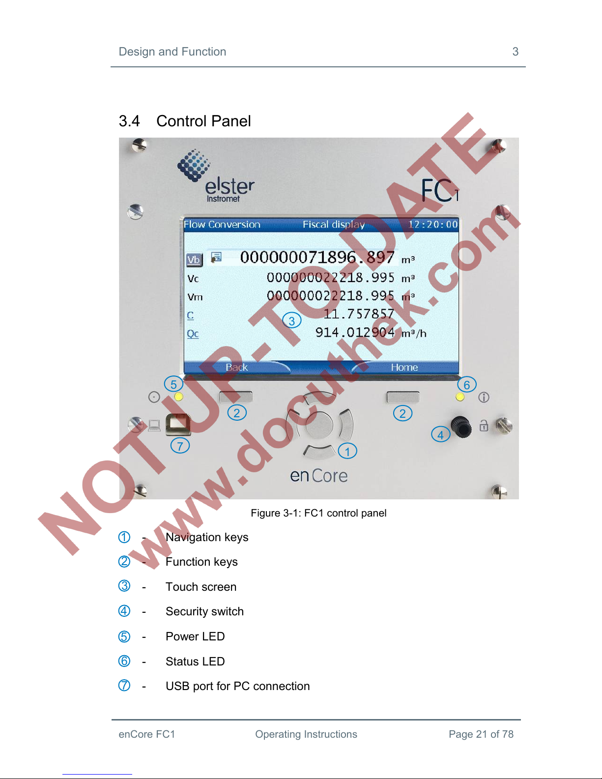
3.4 Control Panel
Figure 3-1: FC1 control panel
- Navigation keys
- Function keys
- Touch screen
- Security switch
- Power LED
- Status LED
- USB port for PC connection
1
2
3
4
5
6
2
4
5
6
7
2
1
3
7
3 Design and Function
Page 22 of 78 Operating Instructions enCore FC1
3.4.1 Device Keys
There are 2 function keys located directly below the touch screen. Pressing
one of these keys activates the corresponding display button which is indi-
cated directly above.
Figure 3-2: Navigation keys
Up
Down
Left
Right
Enter
The navigation keys (Up, Down, Left, Right, Enter) are intended for navi-
gation within the device software's menu as an alternative to an operation
via the touch screen. When a key is pressed, an acoustic signal indicates
the corresponding function has been activated.
3.4.2 Touch Screen
All key functions can be executed from the touch screen. An acoustic signal
indicates that a function was activated.
3.4.3 Operation and Navigation within the Display
Part 1 of the manual contains a general description for operating and
navigating through device displays.
3.4.4 Security Switch
The security switch is a sealable rotary switch. It is closed by turning it
clockwise as far as it will go.
The security switch is part of the enCore concept for limiting user rights. A
closed security switch can prevent certain user actions (e.g. changes of
5
4
3
2
1
1
2
3
4
5

Design and Function 3
enCore FC1 Operating Instructions Page 23 of 78
certain parameters or software download of fiscal or non-fiscal firmware
modules).
3.4.5 LEDs
There are two multicolor LEDs on the front panel, the Power LED and the
Status LED.
Power LED
LED status Meaning
Off Power off; no USB connection
Red Power off; USB connection detected
Green Power on; no USB connection
Orange Power on; USB connection active
Table 3: Power LED
Status LED
LED Status Meaning
Off Power off.
Green, flashing
A green flashing light appears during the start-up
phase after a power failure.
Green, perma-
nently illuminated
The device is working error-free, i.e. there are no
pending or not accepted alarms or warnings in the
error list. Please refer to the corresponding chapter in
Part 1 of the enCore FC1 Manual for detailed
information about alarms and warnings.
A red or yellow colored status LED indicates a currently pending or not
accepted error of alarm or warning type.
The setting of the Acceptance mode parameter determines under which
circumstances errors can be accepted:
Only accept inactive errors means that the acceptance of errors is
not possible as long as they are still pending. This setting is
3 Design and Function
Page 24 of 78 Operating Instructions enCore FC1
usually prescribed for devices used in legal metrology (e.g.
according to MID approval).
Always accept errors means that errors can be accepted as soon
as they have occurred.
The status LED signals the error state as follows (in order of priority):
Red, flashing
The error list contains at least one pending and not
accepted alarm.
Yellow, flashing
The error list contains at least one pending and not
accepted warning.
Red, permanently
illuminated
The error list contains at least one alarm fulfilling one
of the following conditions (depending on chosen
Acceptance mode):
The alarm has already ended but is not yet
accepted.
The alarm is still pending but has already
been accepted.
Yellow,
permanently
illuminated
The error list contains at least one warning fulfilling
one of the following conditions (depending on chosen
Acceptance mode):
The warning has already ended but is not yet
accepted.
The warning is still pending but has already
been accepted.
Table 4: Status LED

Design and Function 3
enCore FC1 Operating Instructions Page 25 of 78
3.5 Interfaces (Rear Side of Device)
Figure 3-3: Rear side of device (example 1/3 mounting width)
- TCP/IP interface (computer network)
- Serial interfaces
- 24V DC power supply
- Optional process boards
1
2
3
4
1
2
3
4

3 Design and Function
Page 26 of 78 Operating Instructions enCore FC1
3.6 Available Process Boards
The configuration of the I/O board mounting is variable. In principle, any I/O
board can be inserted into any slot. If there are any restrictions, they are
mentioned in the following paragraphs describing the individual boards.
Please refer to section 4.3 for a description of how the I/O board
configuration can be modified. Section 4.4 contains connection diagrams for
typical applications.
3.6.1 ExMFE5 Process Board
All ExMFE5 inputs are intrinsically safe ([EEx ib] IIC).
Three NAMUR inputs (Z1+/Z1-, Z2+/Z2-, Z3+/Z3-) for
messages, LF pulses or HF pulses. Pulse inputs are
typically used to connect gas meters that have a pulse
interface.
As an alternative, the first channel is suitable for
connecting a gas meter via an Encoder index.
A resistance input with 4-wire technology (I+/U+/U-/I-),
provided for connecting a Pt100 temperature sensor.
An analog current input 4…20mA (P+ / P-), alternatively
usable as a HART interface. Provided for connecting
measuring instruments that have a current output (e.g.
pressure transmitters) or HART interface (e.g. pressure
transmitters or temperature transmitters).
Two different modes are possible when using the current
input as a HART interface:
Fig. 3-4
- Multi-drop mode for a maximum of 4 HART devices
- Burst mode: 1 HART device
Design and Function 3
enCore FC1 Operating Instructions Page 27 of 78
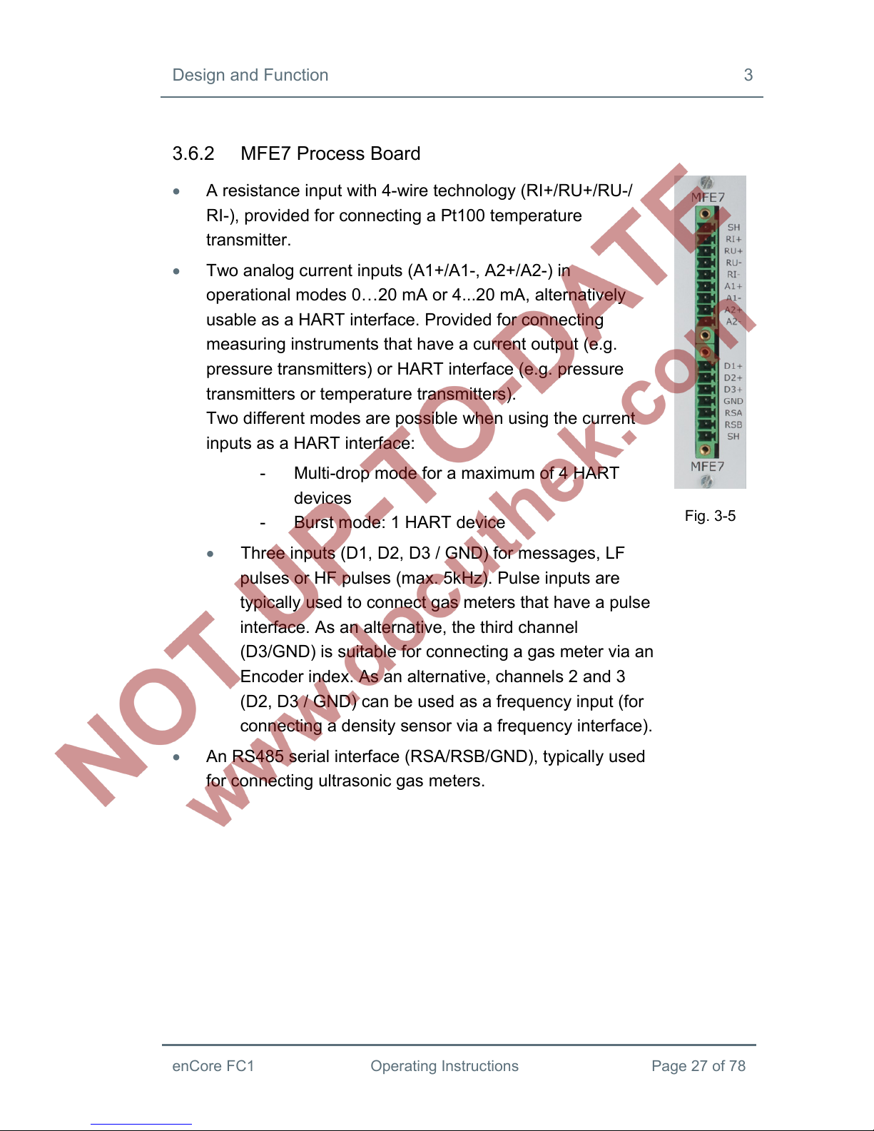
3.6.2 MFE7 Process Board
A resistance input with 4-wire technology (RI+/RU+/RU-/
RI-), provided for connecting a Pt100 temperature
transmitter.
Two analog current inputs (A1+/A1-, A2+/A2-) in
operational modes 0…20 mA or 4...20 mA, alternatively
usable as a HART interface. Provided for connecting
measuring instruments that have a current output (e.g.
pressure transmitters) or HART interface (e.g. pressure
transmitters or temperature transmitters).
Two different modes are possible when using the current
inputs as a HART interface:
- Multi-drop mode for a maximum of 4 HART
devices
- Burst mode: 1 HART device
Three inputs (D1, D2, D3 / GND) for messages, LF
pulses or HF pulses (max. 5kHz). Pulse inputs are
typically used to connect gas meters that have a pulse
interface. As an alternative, the third channel
(D3/GND) is suitable for connecting a gas meter via an
Encoder index. As an alternative, channels 2 and 3
(D2, D3 / GND) can be used as a frequency input (for
connecting a density sensor via a frequency interface).
An RS485 serial interface (RSA/RSB/GND), typically used
for connecting ultrasonic gas meters.
Fig. 3-5

3 Design and Function
Page 28 of 78 Operating Instructions enCore FC1
3.6.3 MSER4 Process Board
Four serial interfaces, each for one protocol channel (CH1,
CH2, CH3, CH4), supporting RS485 / RS422 / RS232. For
example used for connecting gas quality measurement
devices via digital protocol.
For devices with a mounting width of 1/3, a
maximum of one MSER4 board can be mounted in
slot 4 only. For devices with a mounting width of 1/2,
up to two MSER4 boards can be mounted in slots 6
and 7 only.
Fig. 3-6
3.6.4 MFA8 Process Board
One digital message output (D1a/D1b)
Three digital outputs (D2+/D2-, D3+/D3-) for messages or
LF pulses (max. 25 Hz).
Four analog outputs (I1, I2, I3 / I-) 0...20 mA or 4…20 mA
for measurements.
Fig. 3-7
Assembly and Installation 4
enCore FC1 Operating Instructions Page 29 of 78
4 Assembly and Installation
The FC1 is provided for assembly within a 19" cabinet, and is available in
either a mounting width of 1/3 or a mounting width of 1/2 model. Compliance
with the device's installation depth of 170 mm (with plugs approx. 220 mm) is
necessary so the connection terminals located on the rear of the device
remain accessible.
The FC1 must be installed in an Ex-free installation area (electrical
operating area) outside of ex-zones 0, 1 and 2, in accordance with
protection class IP 20.
It is recommended that the FC1 be installed in a swivel frame.
4.1 Line Connection
WARNING!
Risk of explosion
A risk of explosion exists when connecting any lines to the
ExMFE5 board while the FC1 is powered on!
- Only connect transmitter, pulse generator or signal lines
to the ExMFE5 board when the power supply of the FC1
is disconnected completely.

4 Assembly and Installation
Page 30 of 78 Operating Instructions enCore FC1
ATTENTION!
Risk of short circuit
The FC1 device may be damaged when connecting any lines
while the FC1 is powered on.
- Always make sure the power supply of the FC1 is
disconnected completely before making any change to
device wiring or before connecting transmitter, pulse
generator, signal or data lines.
The transmitter, pulse generator, signal and data lines are connected to the
FC1 by using plug-in screw terminals, each of which is located in a cable
terminal box. Fixed screw terminals are used for the power supply
connection.
Special attention must be paid to the intrinsically safe electrical circuits.
Before switching on the power supply, make sure that the plug connections
for the gas meter, pressure and temperature inputs of the ExMFE5 input
board are inserted, since this is the only way the straight line-gap of 50 mm
required in the relevant guidelines can be maintained.
The relevant installation guidelines must be observed when arranging the
wiring.
The lines must be free of tensile stress and must be provided with a kink
protection if the FC1 is mounted in a swivel frame.
Dimension the cable length in such a way that there is no tensile stress on
the cables when the swivel frame is opened up.
It is recommended that all incoming lines be placed on transfer terminals in a
switch cabinet, and then be connected with the FC1 from that point.
However, these terminals have to comply in part with the Ex-regulations, and
must possibly also be sealable, for example in order to fulfill the
requirements of an applicable approval.

Assembly and Installation 4
enCore FC1 Operating Instructions Page 31 of 78
4.2 Power Supply and Grounding
Hazardous Are
a
Safe Are
a
FC1 device
fuse 1A
slow
0V 24V
CPU board
PE
0V
24V
Figure 4-1
The FC1 must be operated with a nominal voltage of 24V DC.
The 24V power supply is connected via the + and – terminals at the rear of
the device, and must be protected externally using a 1A time-delay fuse.
The device is protected internally by means of a self-resetting overcurrent
protection component.
The grounding is connected to PE of the power supply socket for
equipotential bonding.
4.3 Mounting of Process Boards
In delivery condition, the device’s process board equipment is configured as
ordered. Due to the modular hardware concept, it is possible to mount
additional process boards in free slots or to modify the board configuration
even later on.
4 Assembly and Installation
Page 32 of 78 Operating Instructions enCore FC1
For safety reasons, any modifications of the process board
configuration should be carried out only by the manufacturer's
service department or by an appropriately trained specialist
working for the plant operator.
The housing of the device must be opened in order to add or
change process boards. The presence of a metrology expert may
be required for this purpose when the device is being used within
the scope of legal metrology.
ATTENTION!
Risk of short circuit
The FC1 device may be damaged when opening the device
while the FC1 is powered on.
- Always make sure the power supply of the FC1 is
disconnected completely before opening the device.
ATTENTION!
The integrated circuits of process boards may be destroyed
by electrostatic discharge.
- While working on the device for changing the I/O board
configuration, an ESD protected workplace according to
EN 61340-5-1 (ESD pad and ESD wrist strap) must be
used.
Assembly and Installation 4
enCore FC1 Operating Instructions Page 33 of 78
ATTENTION!
Incorrect replacement parts and accessories are a safety risk!
Incorrect or defective replacement parts and accessories may
detract from safety and lead to damage, malfunction, or total
device failure.
- Use only original replacement parts and accessories from
the manufacturer.
- Always contact the manufacturer if you are in doubt.
Procedure for mounting a process board into a free slot
(The procedure for changing or removing boards is similar.)
1. Ensure that all necessary accessories are available: Process board,
fitting labeling plate, and jumpers.
2. Use enSuite to read-out the parameterization of the FC1. (If necessary,
the enSuite installation on the computer has to be executed or updated
before, please refer to section 5.1.2).
3. Disconnect the power supply.
4. Remove all external cable connections to the device.
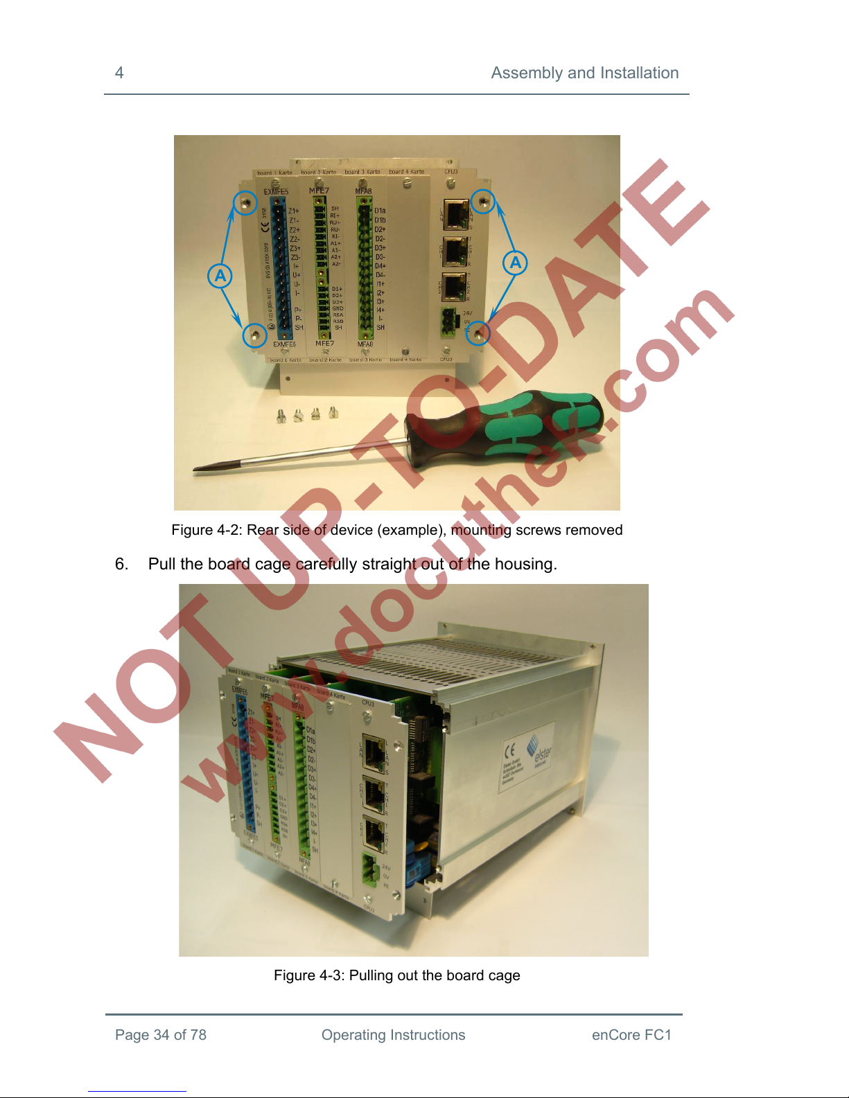
5. Remove the 4 mounting screws (positions A) from the rear side wall of
the device.
4 Assembly and Installation
Page 34 of 78 Operating Instructions enCore FC1
Figure 4-2: Rear side of device (example), mounting screws removed
6. Pull the board cage carefully straight out of the housing.
Figure 4-3: Pulling out the board cage
A
A

Assembly and Installation 4
enCore FC1 Operating Instructions Page 35 of 78
Figure 4-4: Dismounted board cage
7. Check the position for the additional board (number of the slot). This
number has also to be configured as the board’s number, which is
essential for the functioning of the internal I/O bus communication later
on.
To set the number on the board, place jumpers on the respective pin
connector accordingly (please refer to Figures 4-5 and 4-6).
=
jumper
Board position
(slot no.)
1 2 3 4 5 6 7
Figure 4-5: Pin connector with jumper positions
8. Remove the covering plate of the respective slot (2 screws).
9. Insert the board in the slot of the rear side wall (the side for process
connection, blue connector for Ex boards, green connector else, cf.
Figure 4-2).
Make sure that the orientation of the board (top/bottom) is correct:
On the opposite side, the pin connector for the I/O bus connection (with

4 Assembly and Installation
Page 36 of 78 Operating Instructions enCore FC1
retaining clip) has to face downwards, to the bottom of the device (cf.
Figure 4-6, position B). The pin connector for determining the board
number has to face upwards (cf. Figure 4-6, position C).
Pin connector for I/O bus connection (with retaining clip)
Pin connector for determining the board number (here: 4)
Figure 4-6: Interior view of the board cage
10. Place the board’s labeling plate at the rear side of the device and fix
labeling plate and board using the screws.
11. Plug-in the connector for the internal I/O bus at the other side of the
board. The retaining clip closes automatically. Check that all other bus
connectors are still plugged in correctly.
12. Re-insert the board cage carefully into the housing. Press gently to
reinstall the plug-in connection between CPU and display board.
C
B
B
C
Assembly and Installation 4
enCore FC1 Operating Instructions Page 37 of 78
13. Close the device by means of the 4 mounting screws (positions A in
Figure 4-2).
14. Restore all external cable connections to the FC1.
15. Reconnect the power supply.
16. Use enSuite to edit the read-out parameterization by taking the new
board configuration into consideration. Add the new board to the
parameterization (parameter branch Basic System - I/O – I/O boards)
and adjust all settings for its process connection.
Transfer the edited parameterization to the device.
Please refer to FC1 Manual Part 3a for further information on the
parameterization process.
Section 4.4 contains connection diagrams for typical applications.
4.4 Connection Diagrams
This section shows connection diagrams for measuring instruments that are
typically connected to an FC1 flow computer (e.g. temperature and pressure
transmitters, gas meter and gas quality measurement devices).
4.4.1 Pt100 (EEx i) via ExMFE5 Board
Hazardous
Area
Safe Area FC1 device
ExMFE5 board
I+
U+
U-
I-
SH
PT100,
EEx-i
Figure 4-7

4 Assembly and Installation
Page 38 of 78 Operating Instructions enCore FC1
4.4.2 Pt100 (EEx d) via MFE7 Board
Hazardous
Area
Safe Area FC1 device
MFE7 board
RI+
RU+
RU-
RI-
SH
PT100,
EEx-d
Figure 4-8
4.4.3 Analog Pressure Transmitter (EEx i) via ExMFE5 Board
Hazardou
s
Area
Safe Area FC1 device
ExMFE5 board
P+
P-
SH
analog pressure
transmitter
4...20 mA EEx-i
Figure 4-9
Parameterization note: Select Current input.
Assembly and Installation 4
enCore FC1 Operating Instructions Page 39 of 78
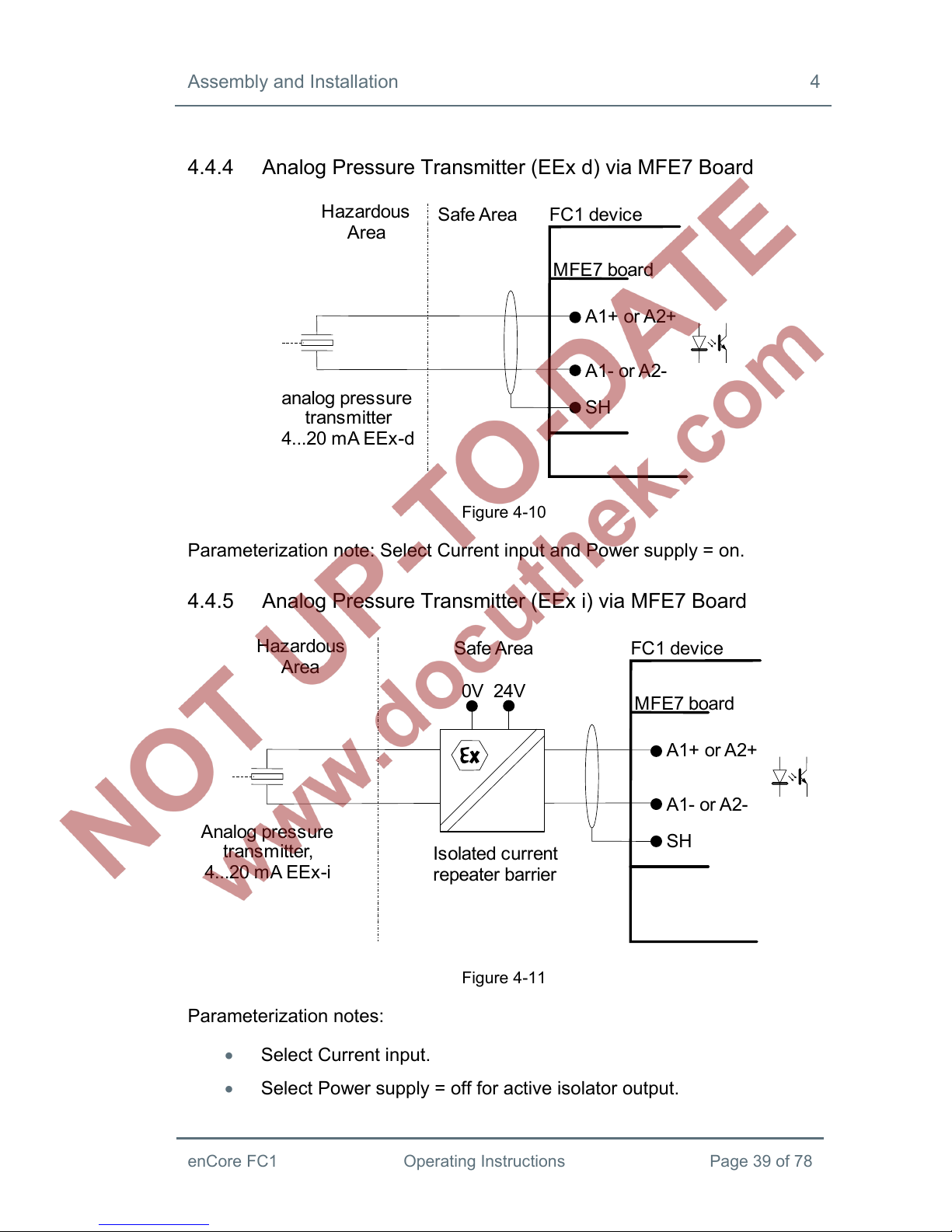
4.4.4 Analog Pressure Transmitter (EEx d) via MFE7 Board
Hazardous
Area
Safe Area FC1 device
MFE7 board
A1+ or A2+
A1- or A2-
SH
analog pressure
transmitter
4...20 mA EEx-d
Figure 4-10
Parameterization note: Select Current input and Power supply = on.
4.4.5 Analog Pressure Transmitter (EEx i) via MFE7 Board
Hazardous
Area
Safe Area FC1 device
MFE7 board
A1+ or A2+
A1- or A2-
SH
A
nalog pressure
transmitter,
4...20 mA EEx-i
0V 24V
Isolated current
repeater barrier
Figure 4-11
Parameterization notes:
Select Current input.
Select Power supply = off for active isolator output.

4 Assembly and Installation
Page 40 of 78 Operating Instructions enCore FC1
Select Power supply = on for passive isolator output.
4.4.6 HART Transmitter (EEx i) via ExMFE5 Board
Hazardou
s
Area
Safe Are
a
FC1 devic
e
ExMFE5 board
P-
P+
SH
HART pressure
transmitter, EEx-i
HART temperatur
e
transmitter, EEx-i
Hand held
Figure 4-12
Parameterization note: Select HART channel
The following HART modes are possible: multi-drop (max. 4 transmitters) or
burst (max. 1 transmitter)

Assembly and Installation 4
enCore FC1 Operating Instructions Page 41 of 78
4.4.7 HART Transmitter (EEx d) via MFE7 Board (Internal Power
Supply)
Figure 4-13
Parameterization note:
Select HART channel and
Power supply = on
The following HART modes are possible: Multi-drop mode (max. 4
transmitters) or burst mode (max. 1 transmitter)

4 Assembly and Installation
Page 42 of 78 Operating Instructions enCore FC1
4.4.8 HART Transmitter (EEx d) via MFE7 Board (External Power
Supply)
Figure 4-14
Parameterization note:
Select HART channel and
Power supply = off
The following HART modes are possible: Multi-drop mode (max. 4
transmitters) or burst mode (max. 1 transmitter)
Assembly and Installation 4
enCore FC1 Operating Instructions Page 43 of 78
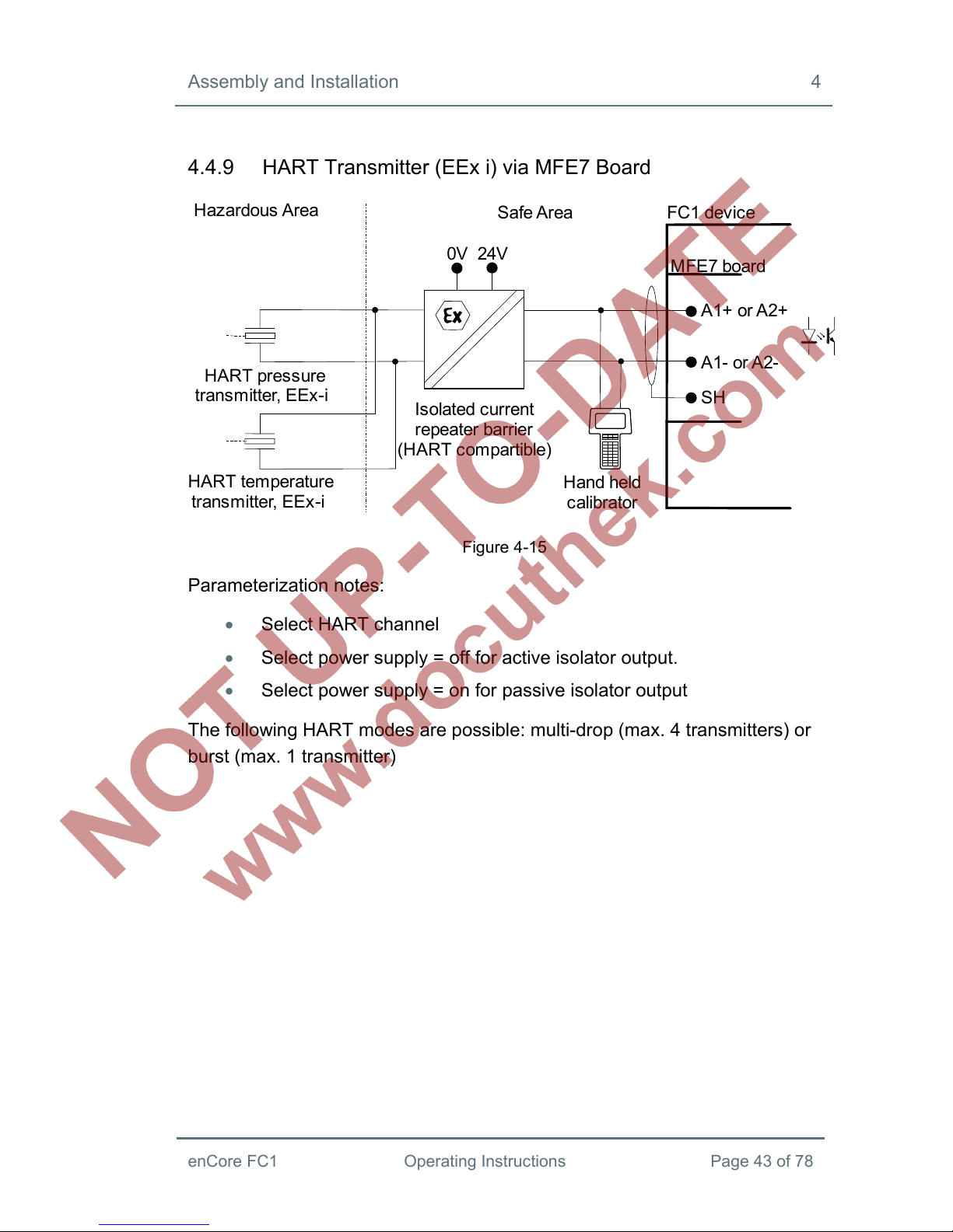
4.4.9 HART Transmitter (EEx i) via MFE7 Board
Hazardous Are
a
Safe Are
a
FC1 device
MFE7 board
A1+ or A2+
A1- or A2-
SH
HART pressure
transmitter, EEx-i
0V 24V
Isolated current
repeater barrier
(HART compartible)
HART temperatur
e
transmitter, EEx-i
Hand held
calibrator
Figure 4-15
Parameterization notes:
Select HART channel
Select power supply = off for active isolator output.
Select power supply = on for passive isolator output
The following HART modes are possible: multi-drop (max. 4 transmitters) or
burst (max. 1 transmitter)

4 Assembly and Installation
Page 44 of 78 Operating Instructions enCore FC1
4.4.10 HART Transmitter (EEx d) via MFE7 Board
(redundant)
Hazardous
Area
Safe Area
FC1 device 2
FC1 device 1
MFE7 board
MFE7 board
A1- or A2-
A1+ or A2+
SH
HART transmitter
EEx-d
A1- or A2-
A1+ or A2+
SH
Hand held
calibrator
Figure 4-16
Parameterization note:
Select HART channel and
Power supply = on (device 1)
Power supply = off (device 2)
Burst HART mode only (max. 1 transmitter).

Assembly and Installation 4
enCore FC1 Operating Instructions Page 45 of 78
4.4.11 HART Transmitter (EEx i) via MFE7 Board
(redundant)
Hazardous
Area
Safe Area
FC1 device 2
FC1 device
1
MFE7 board
MFE7 board
A1- or A2-
SH
A1+ or A2+
HART transmitter
EEx-i
Hand held
calibrator
0V 24V
Isolated current
repeater barrier
(HART compartible,
active output)
A1+ or A2+
A1- or A2-
SH
Figure 4-17
Parameterization note:
Select HART channel and
Power supply = off (device 1)
Power supply = off (device 2)
Burst HART mode only (max. 1 transmitter).

4 Assembly and Installation
Page 46 of 78 Operating Instructions enCore FC1
4.4.12 Gas Meter (Turbine):
Encoder Index, 2 LF/HF Sensors (EEx i) via ExMFE5 Board
Hazardous
Area
Safe Area FC1 device
Turbine:
Encoder and 2
LF / HF sensor
SH
Z3-
Z3+
Z2-
Z2+
Z1-
Z1+
ExMFE5 board
Figure 4-18
4.4.13 Gas Meter (Turbine):
Encoder Index, 2 LF/HF Sensors (EEx i) via MFE7 Board
Hazardous
Area
Safe Are
a
FC1 device
Isolated Pulse
Amplifier
(active output)
Turbine:
Encoder and 2
LF / HF sensor
SH
GND
D3+
D2+
D1+
MFE7 board
24V0V
Figure 4-19

Assembly and Installation 4
enCore FC1 Operating Instructions Page 47 of 78
4.4.14 Gas Meter (Turbine):
SMRI2 Bi-directional: 2 HF Sensors, Flow Direction
Detection (EEx i) via MFE7 Board
Hazardous
Area
Safe Area FC1 device
(1):
Isolated Pulse Amplifier
(active output)
Turbine SMRI bi:
2 HF and 2 MF
sensors
SH
GND
D3+
D2+
D1+
MFE7 board
24V0V
(2):
Flow dir Monitor, e.g.
KFU8-Ex2.D
(
active output
)
(1)
(2)
(1)
MF1
MF2
HF1
HF2
Figure 4-20

4 Assembly and Installation
Page 48 of 78 Operating Instructions enCore FC1
4.4.15 Q.Sonic Ultrasonic Gas Meter:
Serial RS485 (EEx d) via MFE7 Board
Hazardous Area Safe Area FC1 device
RS232C
Service
RS485 to RS232
Converter e.
g
. ADAM 4520
USM Q-Sonic
(EEx-d)
SH
GND
RSB
RSA
MFE7 board
24V 0V
24V
0V
fuse 0,5A
+12/3 0V DC
Ground
Line A
Line B
Data +
Data -
Figure 4-21

Assembly and Installation 4
enCore FC1 Operating Instructions Page 49 of 78
4.4.16 FLOWSIC600 Ultrasonic Gas Meter:
Serial RS485 (EEx d) via MFE7 Board
Hazardous Area Safe Area FC1 device
RS232C
Service
RS485 to RS232
Converter e.g. ADAM 4520
USM
FOWSIC600
(EEx-d)
SH
RSB
RSA
MFE7 board
24V 0V
24V
0V
fuse 0,5A
1+
2-
33
34
Data +
Data -
81
82
Figure 4-22
4 Assembly and Installation
Page 50 of 78 Operating Instructions enCore FC1
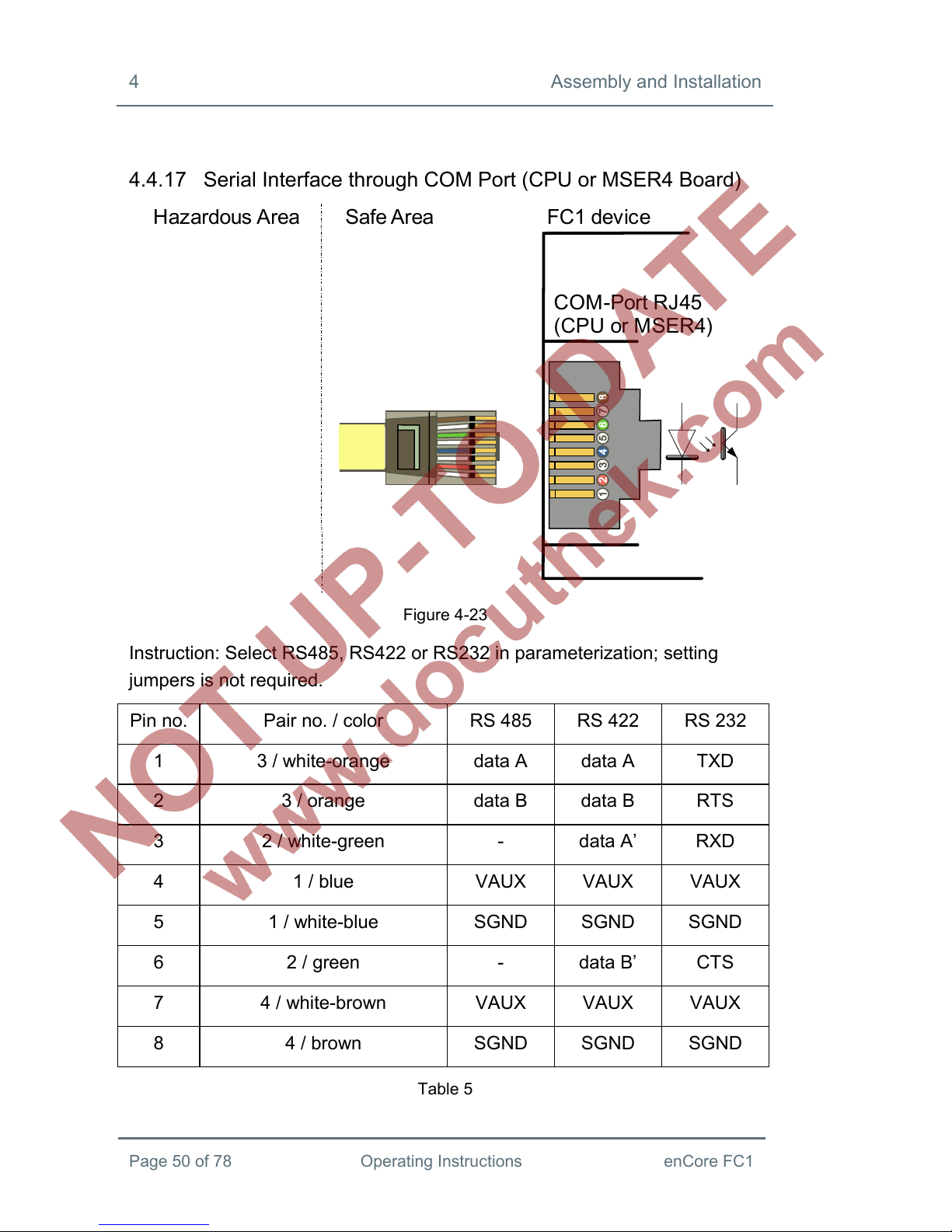
4.4.17 Serial Interface through COM Port (CPU or MSER4 Board)
FC1 device Safe AreaHazardous Area
COM-Port RJ45
(CPU or MSER4)
Figure 4-23
Instruction: Select RS485, RS422 or RS232 in parameterization; setting
jumpers is not required.
Pin no. Pair no. / color RS 485 RS 422 RS 232
1 3 / white-orange data A data A TXD
2 3 / orange data B data B RTS
3 2 / white-green - data A’ RXD
4 1 / blue VAUX VAUX VAUX
5 1 / white-blue SGND SGND SGND
6 2 / green - data B’ CTS
7 4 / white-brown VAUX VAUX VAUX
8 4 / brown SGND SGND SGND
Table 5

Assembly and Installation 4
enCore FC1 Operating Instructions Page 51 of 78
4.4.18 Analog Output (0/4...20mA) via MFA8 Board
Figure 4-24
Parameterization note:
The output current range is selectable (0 to 20 mA or 4 to 20 mA).

4 Assembly and Installation
Page 52 of 78 Operating Instructions enCore FC1
4.4.19 Message Output via MFA8 Board
Figure 4-25
Parameterization note:
For channels 2, 3, and 4 (D2+ D2-, D3+ D3-, D4+ D4-), select Message
output as channel type.

Assembly and Installation 4
enCore FC1 Operating Instructions Page 53 of 78
4.4.20 Pulse Output via MFA8 Board
Figure 4-26
Parameterization note:
For channels 2, 3, and 4 (D2+ D2-, D3+ D3-, D4+ D4-), select Pulse output
as channel type.

5 Device Configuration and Commissioning
Page 54 of 78 Operating Instructions enCore FC1
5 Device Configuration and Commissioning
All newly delivered devices are factory-configured so as to support all
available interfaces.
Setting FC1 parameters, i.e. configuring device functions and adjusting the
device to the actual measuring point, is done on site using enSuite software.
A gas specialist must be consulted for this work step. The presence of a
metrology expert is also required when the device is being used within the
scope of legal metrology.
The online help function in enSuite software contains instructions
for operating enSuite as well as a detailed description of its
parameters.
5.1 enSuite Software
5.1.1 System Requirements
enSuite is a PC software system running on Java. The following minimum
system requirements exist for an enSuite installation:
Microsoft® Windows™ XP or Windows™ 7
A graphics board with a resolution of at least 1024 x 768 pixel
10 GB free space on hard disk
1 GB RAM
Java SE 6 update 19 or higher (32bit)
5.1.2 enSuite Installation
The enclosed CD contains the installation program for enSuite software.
Alternatively, the installation program can be downloaded as compressed
ZIP-file from the software download area on the Elster-Instromet website.
The installation requires administrator rights.
Device Configuration and Commissioning 5
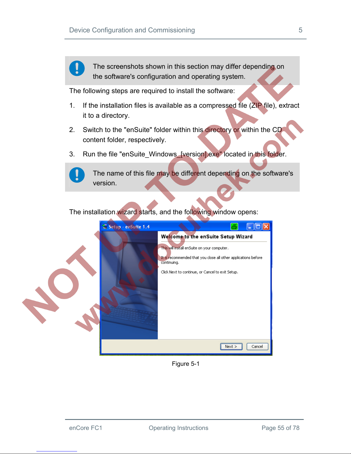
enCore FC1 Operating Instructions Page 55 of 78
The screenshots shown in this section may differ depending on
the software's configuration and operating system.
The following steps are required to install the software:
1. If the installation files is available as a compressed file (ZIP file), extract
it to a directory.
2. Switch to the "enSuite" folder within this directory or within the CD
content folder, respectively.
3. Run the file "enSuite_Windows_[version].exe" located in this folder.
The name of this file may be different depending on the software's
version.
The installation wizard starts, and the following window opens:
Figure 5-1
5 Device Configuration and Commissioning
Page 56 of 78 Operating Instructions enCore FC1
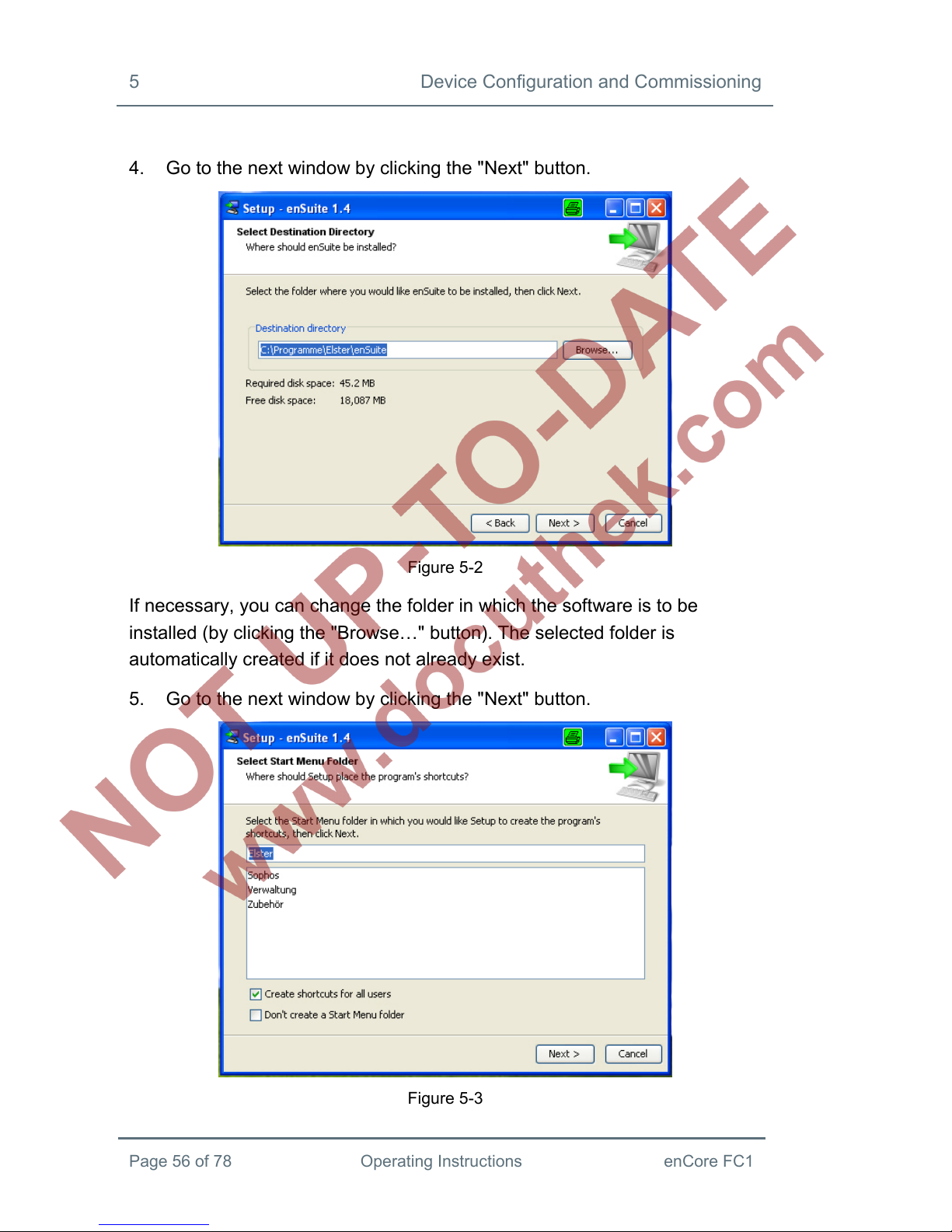
4. Go to the next window by clicking the "Next" button.
Figure 5-2
If necessary, you can change the folder in which the software is to be
installed (by clicking the "Browse…" button). The selected folder is
automatically created if it does not already exist.
5. Go to the next window by clicking the "Next" button.
Figure 5-3

Device Configuration and Commissioning 5
enCore FC1 Operating Instructions Page 57 of 78
This window allows you to specify the program groups in which the program
shortcut should be installed. By default, the shortcut is created in the
program group "Elster".
6. Go to the next window by clicking the "Next" button.
Figure 5-4
This window allows you to choose whether a shortcut to the program should
also be installed on your desktop, in addition to the shortcut in the start
menu.

5 Device Configuration and Commissioning
Page 58 of 78 Operating Instructions enCore FC1
7. Go to the next window by clicking the "Next" button.
Figure 5-5
Installation progress is displayed in this window. The next window opens
automatically after the installation is completed.
Figure 5-6
The end of installation progress is displayed in this window.
Device Configuration and Commissioning 5
enCore FC1 Operating Instructions Page 59 of 78
8. Click on the "Finish" button to confirm installation is complete.
The installation wizard is completed and the enSuite can be started.
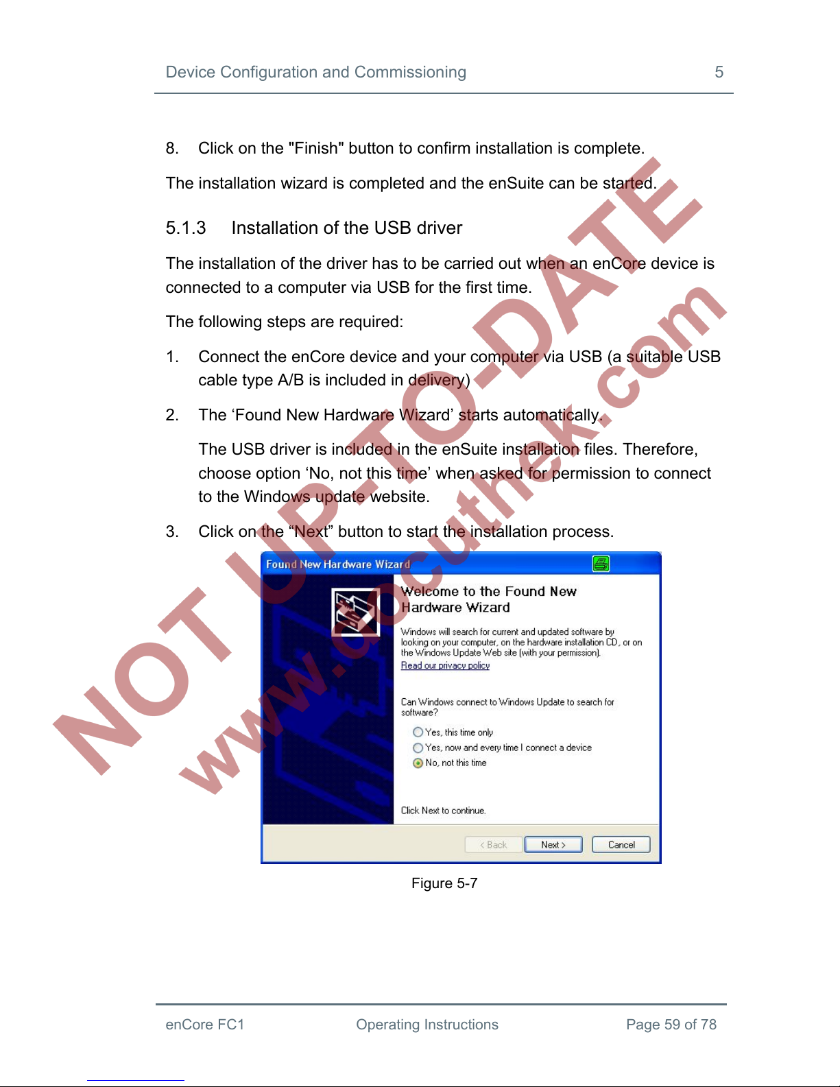
5.1.3 Installation of the USB driver
The installation of the driver has to be carried out when an enCore device is
connected to a computer via USB for the first time.
The following steps are required:
1. Connect the enCore device and your computer via USB (a suitable USB
cable type A/B is included in delivery)
2. The ‘Found New Hardware Wizard’ starts automatically.
The USB driver is included in the enSuite installation files. Therefore,
choose option ‘No, not this time’ when asked for permission to connect
to the Windows update website.
3. Click on the “Next” button to start the installation process.
Figure 5-7

5 Device Configuration and Commissioning
Page 60 of 78 Operating Instructions enCore FC1
4. Within the next window, you have two options.
Figure 5-8
Option 1 (recommended):
Insert the enSuite CD. Choose ‘Install the software automatically’
and click on the “Next” button. The driver is found automatically.
Option 2:
If the enSuite installation has been downloaded from the internet,
the driver cannot be found automatically.
Proceed as follows:
Choose ‘Install from a specific location’.
Click “Next” and select the directory containing the
extracted files of the downloaded installation, then the
subdirectory \drivers.
Click “Next”.

Device Configuration and Commissioning 5
enCore FC1 Operating Instructions Page 61 of 78
5. The software is installed.
Figure 5-9
6. Click “Finish” to close the wizard.
Figure 5-10

5 Device Configuration and Commissioning
Page 62 of 78 Operating Instructions enCore FC1
5.2 Device Parameterization
This section gives brief instructions on how to create a complete
parameterization for enCore devices and how to transfer it into the device
on-site via USB. Please refer to FC1 Manual Part 3a for details on this
process.
The following steps are required:
1. Start enSuite on your computer.
2. Create the USB connection to your enCore device.
3. Use enSuite to create an appropriate parameterization for the device.
4. Transfer the parameterization into the device.
As soon as the transfer of the parameterization starts, a user login
dialog appears on your computer screen. If the initial settings for the
user administration have not been changed, the default administrator
login (user name admin1 and empty password) will work. Otherwise,
you have to regard the individual user configuration of the device.
There are probably parameters that are not allowed to be changed
when the security switch is closed - especially if the device is within the
scope of legal metrology. If a new parameterization affects such
parameters, it is therefore necessary to open the security switch, so that
the presence of an authorized metrology expert may be required.

Device Configuration and Commissioning 5
enCore FC1 Operating Instructions Page 63 of 78
In very rare cases after parameterization and restart, it may happen
that the device shows a ‘No entry’ sign in the home display (see
figure below).
Figure 5-11
The ‘No entry’ sign indicates that the device has started in emergency
mode because of a system error that has been detected during
restart. All functions apart from basic functions for error handling are
deactivated. Typically, this error results from a wrong configuration
and can be solved by transferring a correct parameterization. Please
contact Elster if any further assistance or error diagnosis is required.
5.3 Commissioning the Measurement System
Note: The presence of a metrology expert is required for final commissioning
of the device when it is used within the scope of legal metrology. In this
case, the conditions of the applicable approval must be observed as well.
5.3.1 Checking Device Settings
The legally relevant parameters can be checked in special device displays
(cf. Part 1 of the FC1 Manual). The enSuite software will allow you to carry
out a complete check of the current device parameterization when the
software has an online connection with the device.
5.3.2 Checking Measurement Input Values
Measurement input values, in particular input values for flow computing
(measurement data from gas meters, pressure transmitters, temperature

5 Device Configuration and Commissioning
Page 64 of 78 Operating Instructions enCore FC1
transmitters and, if applicable, gas quality measurement devices) can be
checked on the device display (please refer to part 1 of the Manual).
5.3.3 Checking Output Signals
Parameterized output signals can be measured using appropriate measuring
instruments and checked in that way.
5.3.4 Checking Digital Communication (Modbus, etc.)
Appropriate tools (e.g. a protocol analyzer) can be used to check digital
communication.
5.3.5 Checking Measurements and Calculations
A final check of the accuracy of measurement results and calculations must
be carried out if the device is used within the scope of legal metrology. A
metrology expert is required for this process, and the applicable legal
regulations must be observed.
5.3.6 Sealing (if necessary)
It may be necessary for the device as well as for transmitter, pulse generator
and data lines to be sealed by a metrology expert when it is used within the
scope of legal metrology. The requirements of the applicable approval must
be observed in this case.

Maintenance 6
enCore FC1 Operating Instructions Page 65 of 78
6 Maintenance
The FC1 is practically maintenance-free. Only the battery, which is required
for purposes of data retention when the power supply is switched off, must
be replaced at certain intervals.
This section contains instructions for replacing the battery and cleaning the
device, as well as contact data for customer service and the service hotline.
6.1 Battery Replacement
The FC1 battery mainly comes into use when the FC1 is switched off
permanently, or it is being switched off then switched back on at frequent
intervals. The battery consumption can be neglected while the device is
powered on.
In addition, the battery loses energy as it ages.
The battery must be replaced with a new one at least every 10 years.
Special case: When the device is being stored and therefore permanently
disconnected from power supply, the battery loses approx. 3% of its charge
every month. The battery is therefore completely discharged after 3 years. It
is therefore recommended that the battery be replaced by a new one when
the FC1 has been without power supply for longer than 1 year.
Special case: The battery also loses additional charge when the power
supply is frequently disconnected and reconnected during operation. It is
therefore recommended that the battery be replaced by a new one when the
power supply has been disconnected and reconnected for 1,000 times.
The FC1 automatically signals as soon as battery capacity has dropped to
20% of that of a new battery.
A dead battery may sometimes lead to a loss of the measurement
data that was calculated and saved.
6 Maintenance
Page 66 of 78 Operating Instructions enCore FC1
For safety reasons, the battery should be replaced only by the
manufacturer's service department or by an appropriately trained
specialist working for the plant operator.
The housing of the device must be opened in order to replace the
battery. The presence of a metrology expert may be required for
this purpose when the device is being used within the scope of
legal metrology.
ATTENTION!
Risk of short circuit
The FC1 device may be damaged when opening the device
while the FC1 is powered on.
- Always make sure the power supply of the FC1 is
disconnected completely before replacing the device’s
battery.
Procedure for battery replacement:
A battery of the following type is required: Lithium 3V CR ½ AA.
1. For reasons of security, use enSuite to read-out the parameterization of
the FC1.
2. Disconnect the power supply.
3. Remove all cable connections to the FC1.
4. Remove the FC1 from the switch cabinet.
Maintenance 6
enCore FC1 Operating Instructions Page 67 of 78
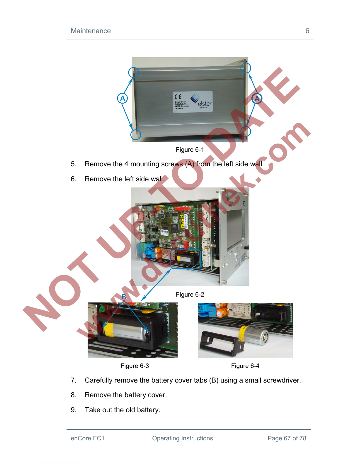
Figure 6-1
5. Remove the 4 mounting screws (A) from the left side wall
6. Remove the left side wall.
Figure 6-2
Figure 6-3 Figure 6-4
7. Carefully remove the battery cover tabs (B) using a small screwdriver.
8. Remove the battery cover.
9. Take out the old battery.
A
B
A
6 Maintenance
Page 68 of 78 Operating Instructions enCore FC1
A capacitor ensures that device data will be retained for 15
minutes.
10. Insert the new battery.
Make sure the polarity is correct when inserting the battery (see
Fig. 6-2 to 6-4)! An incorrect polarity will make itself known through
a loss of data, only after a power failure of greater than 15 minutes.
11. Put the battery cover back on and carefully press on it until it snaps into
place with a soft click.
12. Reassemble the FC1.
13. Restore the cable connections to the FC1.
14. Reconnect the power supply.
The used battery must be disposed of properly, in accordance with the
instructions from the battery manufacturer.
6.2 Cleaning
ATTENTION!
Water penetrating the device will damage it!
Water may penetrate into the device and damage it when it is
cleaned with a cloth that is too wet.
Only use a damp cloth to clean the device.
Normally a dry, soft microfiber cloth is sufficient for cleaning the FC1. A mild
dishwashing liquid solution or a mild glass cleaner can be used for stubborn
stains.

Maintenance 6
enCore FC1 Operating Instructions Page 69 of 78
Cleaners that are recommended for cleaning navigation devices and similar
devices with a touch screen are also suitable for the FC1 screen.
Alternatively, a mixture of 50% isopropyl alcohol and distilled water can be
used to clean the screen.
6.3 Customer Service
Our customer service department is available for technical advice as well as
repairs.
Furthermore, our employees are always interested in new information and
experiences that arise through use of the device and that may be valuable
for improving our products.
You may contact our service hotline with any technical questions.
Tel.: +49 (0) 231 / 93711088
E-mail: support-do@elster.com
6.4 Replacement Parts and Accessories
ATTENTION!
Incorrect replacement parts and accessories are a safety risk!
Incorrect or defective replacement parts and accessories may
detract from safety and lead to damage, malfunction, or total
device failure.
- Use only original replacement parts and accessories from
the manufacturer.
- Always contact the manufacturer if you are in doubt.

6 Maintenance
Page 70 of 78 Operating Instructions enCore FC1
You must contact the responsible customer service department for
replacement parts and accessories (see section 6.3).
6.5 Warranty Conditions
You will find our current warranty conditions in the General Terms and
Conditions, e.g. on the Internet at:
http://www.elster-instromet.com/de/AGB.html
Decommissioning / Disposal 7
enCore FC1 Operating Instructions Page 71 of 78
7 Decommissioning / Disposal
7.1 Storage
ATTENTION!
Material damage from formation of condensation!
Storing the device can lead to the formation of condensation
resulting from variations in temperature. This may result in the
device malfunctioning at a later time.
- After the device was stored or transported in cold weather
or if it was subject to extreme variations in temperature, it
must be slowly brought to room temperature before it is
commissioned.
- The device must undergo a waiting period of at least 12
hours before it is put into operation if condensation formed
during storage.
The device's time may no longer be exactly correct after it is stored
for longer periods; i.e. its clock must be checked and set if
necessary.
It is also possible counters and archive files may have been
deleted.
Counters and archive files as well as time and date settings are
deleted if the device's power supply was interrupted during storage
because the battery was disconnected.
The battery (operational life of 3 years) must be replaced in case of
longer device storage times (cf. section 6.1).

7 Decommissioning / Disposal
Page 72 of 78 Operating Instructions enCore FC1
The following regulations apply for storage:
Relative humidity may not exceed 93%.
Packaging must only be stored in closed areas.
Storage temperature must be between -25° C and +60° C.
Mechanical vibrations must be avoided during storage.
7.2 Disposal
The manufacturer will take care of proper disposal of the FC1 after the
operational life of the device expires.
Address for returning the FC1:
Elster GmbH
Steinern Straße 19 – 21
D - 55252 Mainz-Kastel
Germany

Technical Data 8
enCore FC1 Operating Instructions Page 73 of 78
8 Technical Data
8.1 General
Dimensions / housing Plug-in unit in 19” design, 3 height units (3HU), 1/2
or 1/3 width.
Overall depth without plugs approximately 170 mm,
with plugs approximately 220 mm. Process
interfacing at the rear, control panel at the front.
Ambient conditions Ambient temperature range -10 °C to +55 °C.
Humidity < 90 %, non-condensing.
Installation outside Ex zones 0, 1, 2 only.
IP protection class IP20
Storage temperature -25°C to +60°C
Weight Approx. 1.2 kg (fully equipped).
Power supply 24 V DC +/- 20 %, power consumption up to 12 W
(typically 5 W).
Optionally: 230 V AC via external power supply.
Display / control panel 4.3“TFT color display with touch screen,
480x272x3 pixels, LED background illumination.
4 navigation and 2 function keys.
2 multi-color LEDs for power and status indication.
Sealable security switch.
Table 6: General technical data

8 Technical Data
Page 74 of 78 Operating Instructions enCore FC1
8.2 Inputs
ExMFE5 input board 3 NAMUR inputs [EEx ib] IIC for LF or HF
pulses (max. 5 kHz) or messages. One of
these inputs can be used alternatively for
connecting an encoder index.
Analog input for transmitters with 4 - 20mA
interface [EEx ib] IIC, alternatively suitable for
a connection of transmitters with HART
interface (one transmitter in burst mode or up
to four transmitters in multi-drop mode).
Pt-100 temperature sensor input (4-wire
technology), [EEx ib] IIC.
MFE7 input board 3 inputs (24 V DC) for LF or HF pulses (max. 5
kHz) or messages. One of these inputs can be
used alternatively for connecting an encoder
index or as frequency input.
2 analog inputs for transmitters with 4 - 20mA
interface, alternatively suitable for a connection
of up to four transmitters with HART interface
(one transmitter in burst mode or up to four
transmitters in multi-drop mode).
Pt-100 temperature sensor input in 4-wire
technology.
Table 7: Inputs: Technical data
Technical Data 8
enCore FC1 Operating Instructions Page 75 of 78
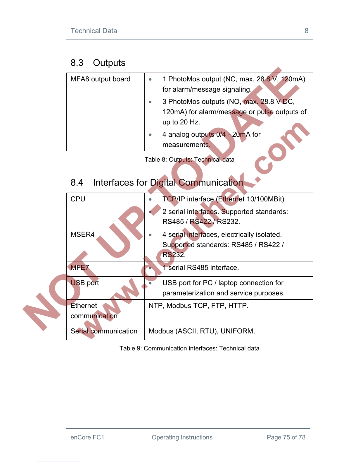
8.3 Outputs
MFA8 output board 1 PhotoMos output (NC, max. 28.8 V, 120mA)
for alarm/message signaling.
3 PhotoMos outputs (NO, max. 28.8 V DC,
120mA) for alarm/message or pulse outputs of
up to 20 Hz.
4 analog outputs 0/4 - 20mA for
measurements.
Table 8: Outputs: Technical data
8.4 Interfaces for Digital Communication
CPU TCP/IP interface (Ethernet 10/100MBit)
2 serial interfaces. Supported standards:
RS485 / RS422 / RS232.
MSER4 4 serial interfaces, electrically isolated.
Supported standards: RS485 / RS422 /
RS232.
MFE7 1 serial RS485 interface.
USB port USB port for PC / laptop connection for
parameterization and service purposes.
Ethernet
communication
NTP, Modbus TCP, FTP, HTTP.
Serial communication Modbus (ASCII, RTU), UNIFORM.
Table 9: Communication interfaces: Technical data

9 Index
Page 76 of 78 Operating Instructions enCore FC1
9 Index
A
Accessories 69
Assembly instructions 29
B
Battery cover 67
Battery replacement 65
C
Cleaner 69
Cleaning 68
Commissioning 63
Condensation 71
Control panel 21
Customer service 69
D
Danger word 8
Decommissioning 71
Device parameterization 62
Disposal 71, 72
E
enCore 18
enSuite 18
installation 54
ExMFE5 board 26
F
FC1 device description 20
Flow computer 18
G
Gas specialist 10
H
Hazard level 8
Hazard warnings 8
I
I/O boards 26
Board number 35
Mounting 33
Intended use 15
Interfaces 25
K
Keys 22
L
LEDs 23
Limitation of liability 10
Line connection 29
M
Maintenance 65

Index 9
enCore FC1 Operating Instructions Page 77 of 78
Metrology expert 10
MFA8 board 28
MFE7 board 27
MSER4 board 28
O
Operator liability 16
Overcurrent protection
component 31
P
Polarity 68
Process boards 20
Q
Qualified electrician 10
R
Relative humidity 72
Repairs 69
Replacement parts 69
S
Safety installations 17
Safety instructions 9, 13
Scope of delivery 6
Security switch 22
Specialist 9
Standards 11
Storage 71
Straight-line gap 30
T
Target group definition 9
Technical data 73
Trained individual 9
Transport 71
U
USB driver
installation 59
User login 62
Users 16
V
Vibrations 72
W
Warranty conditions 70
Wiring 30

10 Appendix
Page 78 of 78 Operating Instructions enCore FC1
10 Appendix
enCore FC1: Declaration of Conformity
ExMFE5 board: EC Type Examination Certificate (ATEX)


- English translation of the German original certificate –
EX EXAM
BBG Prüf- und Zertifizier GmbH
(1)
EC Type Examination Certificate
(2)
- Council Directive 94/9/EC -
Protective devices and systems intended for use
in potentially explosive atmospheres
(3)
BVS 05 ATEX E 019
(4)
Device: Process Board Type EXMFE5
(5)
Manufacturer: FLOW COMP Systemtechnik GmbH
(6)
Address: D – 44357 Dortmund
(7) This device type and its various permissible versions are specified in the appendix to this Type
Examination Certificate.
(8) The EXAM BBG Prüf- und Zertifizier GmbH certification body, notified body no. 0158 in
accordance with Article 9 of the European Parliament and Council Directive 94/9/EC of 23 March
1994, certifies that this device has been found to comply with the Essential Health and Safety
Requirements relating to the design and construction of protective devices and systems intended for
use in potentially explosive atmospheres according to Annex II to the Directive.
The test results are recorded in the test report BVS PP 05.2005 EC.
(9) The compliance of the device with the Essential Health and Safety Requirements has been assured
by compliance with
EN 50014:1997 + A1 – A2 General Requirements
EN 50020:2002 Intrinsic Safety ‘i’
(10) If the character “X” is placed after the certificate number, it indicates that the device is subject to
special requirements for safe use as referenced in the appendix to this certificate.
(11) This EC type examination certificate refers only to the design and construction of the specified
device in accordance with Council Directive 94/9/EC.
Further requirements of this Directive, which are not covered by this certificate, apply to the
manufacture and supply of this device.
(12) The marking of the device shall include the following details:
Ex II (2)G [EEx ib] IIC
EXAM BBG Prüf- und Zertifizier GmbH
Bochum, 31 January 2005
_______________________ _____________________
Certification Body Head of Unit
Page 1 of 3 of BVS 05 ATEX E 019
This certificate may only be circulated without alteration.
Dinnendahlstrasse 9 44809 Bochum Tel. +49 (201) 172 3947 Fax +49 (201) 172 3948

- English translation of the German original certificate –
EXAM
BBG Prüf- und Zertifizier GmbH
(13)
Appendix to
(14)
EC Type Examination Certificate
BVS 05 ATEX E 019
(15) 15.1 Object and Type
Process Board Type EXMFE5
15.2 Description
The process board that will be installed outside potentially explosive atmospheres serves as power
supply and for processing the signals of up to five sensors being installed in potentially explosive
atmospheres.
15.3 Characteristics
15.3.1 Non-intrinsically safe supply and signal circuits (connector ST1)
Nominal voltage DC 24 V
Maximum voltage Um AC 250 V
15.3.2 Intrinsically safe output circuits (terminal strip connections)
15.3.2.1 Channel 1 (terminals Z1+, Z1-)
Channel 2 (terminals Z2+, Z2-)
Channel 3 (terminals Z3+, Z3-)
Values per circuit
Voltage Uo DC 8.6 V
Current Io 14.9 mA
Power Po 32 mW
Linear output characteristic
Max. external inductivity Lo 10 mH
Max. external capacitance Co 0.5 µF
15.3.2.2 Channel 4 (terminals I+, I-, U+, U-)
Voltage Uo DC 5.9 V
Current Io 14.4 mA
Power Po 21 mW
Linear output characteristic
Max. external inductivity Lo 10 mH
Max. external capacitance Co 0.5 µF
15.3.2.3 Channel 5 (terminals P+, P-)
Voltage Uo DC 21 V
Current Io 73.9 mA
Power Po 388 mW
Linear output characteristic
Max. external inductivity Lo 5 mH
Max. external capacitance Co 0.18 µF
15.3.3 Ambient temperature range Ta -20°C to +70°C
Page 2 of 3 of BVS 05 ATEX E 019
This certificate may only be circulated without alteration.
Dinnendahlstrasse 9 44809 Bochum Tel. +49 (201) 172 3947 Fax +49 (201) 172 3948

- English translation of the German original certificate –
EXAM
BBG Prüf- und Zertifizier GmbH
(16) Test report
BVS PP 05.2005 EC, as of 31 January 2005
(17) Special conditions for safe use
None
Page 3 of 3 of BVS 05 ATEX E 019
This certificate may only be circulated without alteration.
Dinnendahlstrasse 9 44809 Bochum Tel. +49 (201) 172 3947 Fax +49 (201) 172 3948


 Loading...