

Page 1

INSTALLATION INSTRUCTIONS
The Kent Range of Domestic Meters
V100, V110 & V200
Volumetric in-line cold water meters
All Elster water meters are manufactured and tested in
accordance with either BS5728 or BSEN14154 according to
the appropriate type approval and comply with the relevant
UK Weights and Measures regulations. The meters are
suitable for cold potable water up to a temperature of 30ºC
and working pressure of 16 bar (10 bar only for V110).
If the meter has been provided with an encoded register,
please refer to the appropriate additional instructions:
1. Electronic Meter Reading (EMR) Installation Instructions
ref. 8593D9791.
2. Electronic Meter Reading (InVISION EMR) Installation Instructions
ref. 8505A2750.
The meter must be fully flooded with clean cold water at all times.
No air or water/air mixtures should be allowed
to flow through the meter, otherwise errors
and damage may result.
20724 V100, V110, V200 Inst Instr EN Master AW.indd 1
28/02/2013 13:02
Page 2

Handling
Water meters are accurate measuring devices and although of robust
construction should be treated with due care. The meters should
remain within their protective packaging until the point of installation.
Storage
Storage temperatures should remain within a range of 5 to 10ºC,
avoiding direct sunlight and heat.
Installation
The meter may be connected to horizontal, vertical or inclined pipes.
The installation should comply with BS5728 or BSEN14154, according to
the appropriate meter type approval and respect all relevant local byelaws. Only approved sealing materials should be used for making pipe
connections. The meter should be installed in a position to ensure it is
fully flooded with clean cold water at all times, in a frost protected area.
The meter should be accessible for ease of reading and should not be
subjected to installation induced stresses or vibration. Failure to do so
may result in meter damage and leakage occurring.
Earthing caution:
National legislation and local rules in force concerning the use of water
pipes for earthing shall always be consulted and adhered to. Where
the meter installation forms part of the electrical earthing, in order to
minimise the risk to operational staff, there shall be a permanent shunt
for the water meter and its associated fittings.
To enable the meter to be removed it is recommended valves be fitted
upstream and downstream of the meter, together with a drain cock
between the meter and downstream valve.
20724 V100, V110, V200 Inst Instr EN Master AW.indd 2
28/02/2013 13:02
Page 3
Meter Installation Instructions
1. Prior to installation of the meter, new or existing inlet and outlet
pipework must be thoroughly flushed free of foreign material,
using a make-up piece of pipe where the meter is to be fitted.
2. Install the meter with the flow direction arrow pointing in the
direction of flow.
3. Tighten all meter couplings.
Start-up procedure
Commissioning:
The meter’s measuring device may be damaged if subjected to full flow
conditions prior to expelling air from the pipeline.
4. With the downstream valve open, slowly open upstream valve,
until all air is expelled from the meter. Fully open the upstream
valve once all the air has been expelled.
5. Observe that the register is responding to water throughput.
6. Close downstream outlet, (meter register should stop).
7. Check all connections for leaks.
Installation Leakage
If the connections and fittings show signs of leakage, carry out start-up
procedure again.
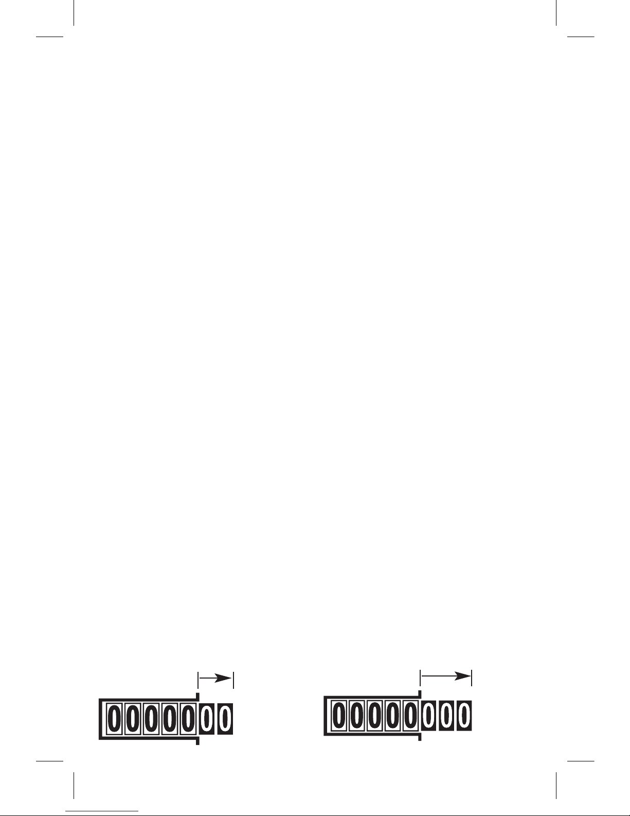
How to read your meter
Mechanical register:
The reading is from left to right.
Black numbers on white rollers denote cubic metres. White numbers
on red rollers (or white numbers on black rollers, as is the case with
InVISION) denote litres. (1000 Litres = 1 Cubic Metre).
litres
litresAlternative
20724 V100, V110, V200 Inst Instr EN Master AW.indd 3
28/02/2013 13:02
Page 4

Electronic register:
The reading is from left to right.
The main display of large digits indicates billable units in cubic metres.
The smaller digits, in the red frame, indicate sub-units.
(1000 Litres = 1 Cubic Metre)
012356
02653
Billable units
Sub units
(red frame)
Tell-tale
Main Display
Display: Self-checking mode Display: Alert status mode
888888
88888
E
All of the display segments
are temporarily activated
for self-checking.
An alert is signalled by an “E” in the alert flag
field. The type of alert can be identified by the
alert code. Refer to the operating instructions.
In the absence of an alert, the five dashes will
be seen in the alert code field, as shown.
012356
-----
Alert code Alert flag
The Tell-tale signals that the meter is in measurement mode and can
be activated by manual rotation of the register without water flowing.
The Tell-tale will continue to display for a short period after activation.
During normal operation, the display will periodically show a selfchecking and alert status mode.
20724 V100, V110, V200 Inst Instr EN Master AW.indd 4
28/02/2013 13:02
Page 5

Special installation and maintenance
instructions for polymer bodied meters
In addition to the instructions given in this document, special
consideration is required when installing and maintaining polymer
bodied meters.
1. The meter installation site should be protected from frost, direct sunlight
and away from heat sources.
2. The installation type and position should minimise the risk of chemical
contamination through flooding or soil contact, or by run-off from
adjacent surfaces or fittings.
3. Care must be taken to ensure that any chemicals used during the
installation process, such as cleaning fluids or jointing fluxes, are not
permitted to come into contact with the meter.
4. It is essential that stresses due to poor installation methods should not
act across the meter body. Ensure the correct gap is provided in the
pipework to fit the meter length. Ensure the upstream and downstream
pipe connectors are aligned and sealing faces are parallel. Ensure
upstream and downstream pipework is firmly anchored.
5. Polymer pipe connection pieces should be used. If brass connection
pieces have to be used, they should be of a dezincification resistant
(DZR) grade.
6. Only the provided connector seals should be used. The use of PTFE tape
or sealing fluids may damage the meter.
7. For V110 and V200 polymer meters it is important that the foam
washers, provided at the end of both connection threads, remain in
place after installation.
8. The pipe connectors should be carefully threaded onto the meter by
hand to avoid cross threading. The final tightening with a spanner
should not exceed 20Nm, avoiding damage to, or loading across the
meter body.
20724 V100, V110, V200 Inst Instr EN Master AW.indd 5
28/02/2013 13:02
Page 6

9. The meter connections must be completely water tight when
the system is pressurised.
10. Once installed, the meter should not be painted or come into contact
with chemicals such as household cleaning fluids.
11. When making repairs to pipework near to the meter installation,
care should be taken to prevent damage to the meter, especially when
using a heat source.
Health and Safety at Work Act 1974
1. We wish to inform you that in accordance with Section 6 of the
above Act, we take every care, as far as is reasonably practicable
to ensure that our products are safe without risk to health when
properly handled, transported, installed, used, maintained and
disposed. However, as manufacturers and suppliers of a wide
range of products, we would advise you that related information
for these products will be found in the following literature.
• Regulations(suchastheCOSHHRegulations,ManualLifting
Regulations, Personal Protective Equipment Regulations),
British Standards and other applicable ISO and European
Specifications and Codes of Practice, as applicable to the
intended application of the products.
• Regulationsforelectricalequipmentofbuildings(publishedby
the Institution of Electrical Engineers).
• CataloguesandproductleaetsofthisCompanyorliterature
which may be obtained by specific request to the Company.
20724 V100, V110, V200 Inst Instr EN Master AW.indd 6
28/02/2013 13:02
Page 7

2. It is important that the products concerned should be installed,
handled, transported, commissioned and maintained by, or under
the supervision of, competent persons in accordance with good
engineering practice and:
• IEERegulationsfortheelectricalequipmentofbuildings.
• Regulations,British,European,ISOandotherstandards,
specifications and Codes of Practice, as applicable to the
intended application of products, i.e. Water Supply Bye-Laws.
• StatutoryRequirements.
• AnyinstructionsspecicallyadvisedbytheCompanyand,
where appropriate, with particular reference to information
marked on the product. The product must only be used in
the condition supplied or specified by the Company, without
modification, and for the purpose for which it was designed.
3. In accordance with your statutory duties to employees and other
persons, you are therefore requested to take such steps as are
necessary to ensure that any appropriate information relevant to
our products is made available by you to everyone concerned.
The Company takes no responsibility for any failure to comply with
the above guidelines.
Pressure equipment directive 97/23/EC
This product is applicable in networks for the supply, distribution and
discharge of water and associated equipment and is therefore exempt.
20724 V100, V110, V200 Inst Instr EN Master AW.indd 7
28/02/2013 13:02
Page 8

Leaflet ref. 8593C9780 Issue 9
The Company’s policy is one of
continuous improvement and the right
is reserved to modify the
specifications without notice.
DECLARATION OF CONFORMITY
We, Elster Water Metering Limited, 130 Camford Way, Sundon Park,
Luton, Bedfordshire, LU3 3AN hereby declare that the meter type:
V100, V110 & V200
conforms, where applicable, to the following directives:-
Measuring Instrument Directive 2004/22/EC
Electromagnetic Compatibility (EMC) Directive 2004/108/EC
RoHS2 DIRECTIVE 2011/65/EU
Signature:…………………………………………
Full Name: Nigel Maynard
Position: Quality Manager
Date: August 2014
Measuring instruments directive 2004/22/EC
This Declaration of Conformity applies to meters verified according to
the directive and bearing the relevant CE verification mark.
Elster Water Metering Limited
130 Camford Way
Sundon Park
Luton
Bedfordshire
LU3 3AN
United Kingdom
T: +44 (0) 1582 846400
F: +44 (0) 1582 564728
water.metering@elster.com
www.elstermetering.com
 Loading...