

Page 1

The Kent Range of Metering Products
T-Probe
For retro-fitting to V100 and V110 meters
INSTALLATION INSTRUCTIONS
The brass bodied V100 (Kent PSM) and some versions of the
thermoplastic V110, can be specified with the facility for a magnetically
operated (reed switch) pulsed output, by the retrofitting of a dedicated
probe assembly.
The probe is fitted with a 100Ω series resistor to protect the reed switch
from power surges and is usually provided with a 5 metre length of
cable, terminating in a sealed flying lead.
Most V100 and V110 meters have the probe location hole
in the body and a driving magnet fitted. V100 or V110
meters without this facility cannot be retro-fitted with
a T-probe.
Page 2
Location and Operating Principle:
The Probe position is next to the counter, on the top shoulder of the
meter body, protected with a removable plastic cover (See ‘A’ opposite).
The volt free pulse is generated from the counter rotation, which has a
two pole circular magnet fitted to the end roller. As the magnet rotates
and opposite poles pass the reed switch, it pulls the reed contacts
together. This produces 2 pulses per revolution of the end roller.
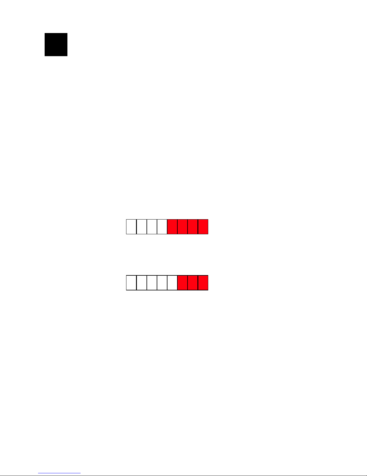
Where there are 4 red rollers, (15mm and 20mm size), this will generate
1 Pulse / 0.5 Litre.
Where there are 3 red rollers, (25mm, 30mm and 40mm size), this will
generate 1 Pulse / 5.0 Litre.
Probe Fitting Instructions:
Remove and discard the plastic protective plug. Insert the probe into
the socket and align with screw hole.
Fit the retaining screw through the hole in the probe. (The reed switch
within the probe is self-positioning, with the screw firmly in place). (See
‘B’ opposite). To prevent unauthorised interference, the screw head can
be security lock-wired to the meter body with copper wire and a lead
seal, making the probe installation completely tamperproof.
V100 & V110 T-PROBE
INSTALLATION INSTRUCTIONS
2
1 2 3 4 0 0 0 0
1 2 3 4 5 0 0 0
Page 3

3
‘A’ Probe location position under
protective plug.
‘B’ Probe fitted and screwed in
place with security screw.
Cable Identification and Wiring Details:
The factory fitted cable used for the T-Probe is defined as 4 x 7 / 0.2mm
with Red, Blue, Black and Yellow as the core colours, contained within
a white outer sheath.
There are 2 wiring variants available, identified as follows:
Common Loop-Back: ‘TL1’ Product Code: RR1LRBX005X
Separate Loop-Back: ‘TL2’ Product Code: RR1LRTX005X
(Standard Version)
For ‘TL1’ variant, the BLACK and YELLOW cores are the volt free pair.
The loop-back is across RED and YELLOW cores. The Blue core can
be cut back and discarded, as it is not connected.
Page 4

Health and Safety at Work Act 1974
1. We wish to inform you that in accordance with Section 6 of the
above Act, we take every care, as far as is reasonably practicable to
ensure that our products are safe without risk to health when
properly handled, transported, installed, used, maintained and
disposed. However, as manufacturers and suppliers of a wide range
of products, we would advise you that related information for these
products will be found in the following literature.
●
Regulations (such as the COSHH Regulations, Manual Lifting
Regulations, Personal Protective Equipment Regulations), British
Standards and other applicable ISO and European Specifications
and Codes of Practice, as applicable to the intended application
of the products.
●
Regulations for electrical equipment of buildings (published by the
Institution of Electrical Engineers).
●
Catalogues and product leaflets of this Company or literature
which may be obtained by specific request to the Company.
4
Continued on page 5
For ‘TL2’ variant, the RED and BLUE cores are the volt free pair. The
loop-back is across the BLACK and YELLOW cores. These connections
are not otherwise polarity sensitive.
Note: The reed switch assembly is rated at 50 Vdc maximum working.
The duty cycle of the switch closure is typically 70% on, 30% off.
Page 5

2. It is important that the products concerned should be installed,
handled, transported, commissioned and maintained by, or under
the supervision of, competent persons in accordance with good
engineering practice and:
●
IEE Regulations for the electrical equipment of buildings.
●
Regulations, British, European, ISO and other standards,
specifications and Codes of Practice, as applicable to the
intended application of products, i.e. Water Supply Bye-Laws.
●
Statutory Requirements.
●
Any instructions specifically advised by the Company and, where
appropriate, with particular reference to information marked on
the product. The product must only be used in the condition
supplied or specified by the Company, without modification, and
for the purpose for which it was designed.
3. In accordance with your statutory duties to employees and other
persons, you are therefore requested to take such steps as are
necessary to ensure that any appropriate information
relevant to our
products is made available by you to everyone concerned. The
Company takes no responsibility for any failure to comply with the
above guidelines.
5
Continued from page 4
 Loading...