

Page 1
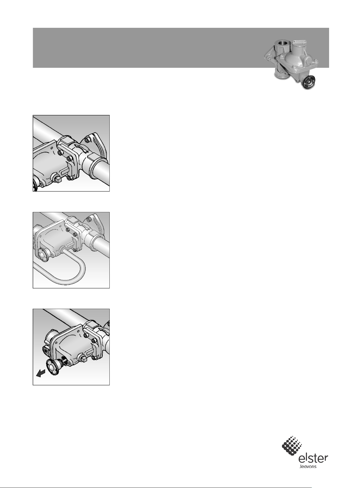
Fig. 1
Fig. 2
Fig. 3
S300
Commissioning Instructions
INSTALLATION CONDITIONS
Body pressure range: 0
Temperature range:
OPERATING INSTRUCTIONS
•
•
•
•
•
•
FITTING REGULATOR INTO PIPEWORK (A)
1.
from inlet and outlet (and external
2.
3. The direction of gas flow must be the same as the arrows on the OPSS body.
4.
inting compound approved to
5. If external impulsed unit, connect impulse pipe as per national standards.
OPSS COMMISSIONING INSTRUCTIONS (For non preset units)
1.
2.
3.
cock OPSS unit and release spindle gently.
4.
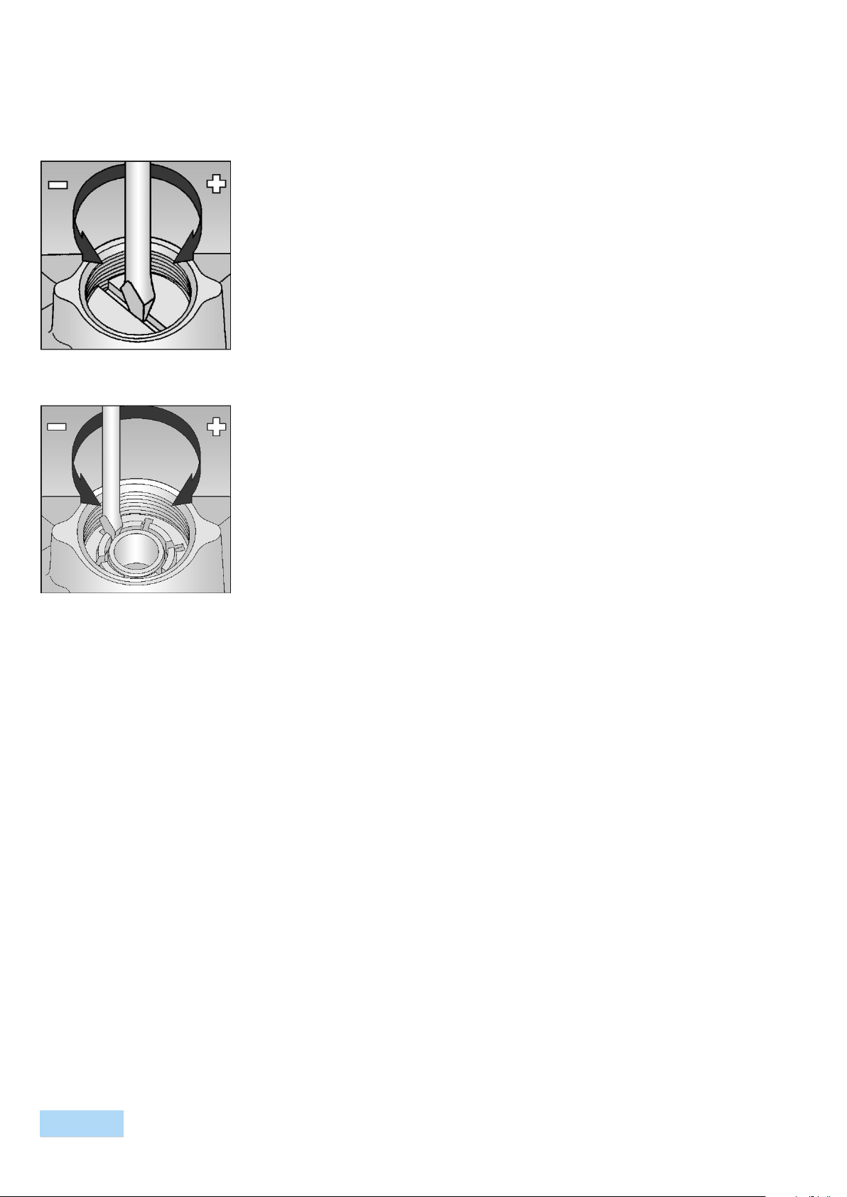
5. Insert a flat bladed screwdriver into slot on the OPSS spring adjuster. See Fig.
6.
7. Apply external pressure source to a suitable point on the downstream
Note: If pressure point on underside of OPSS unit is used as external
, care must be taken to ensure that pressures are equalised across
8.
) until OPSS device trips off.
9.
10.
-
11.
off. Trim adjustment
- 20 Bar
-20ºC to +70 ºC
Ensure that this product is suitable for the chosen application.
Installation, adjustment and maintenance by authorised, trained personnel only.
When being fitted to an appliance, refer to the appliance manufacturers instructions.
Ensure that the installation provides adequate protection to prevent over
pressurisation.
Traffic, wind and earthquake loadings should be considered when specifying the
installation.
The unit should be protected from the decomposition of unstable fluids.
Remove the plastic protection plugs
impulse hole if applicable)
Ensure that installation pipework is thoroughly clean.
See Fig. 1.
Install the OPSS into pipework using a jo
national standards.
See Fig. 2.
Turn off upstream and downstream isolation valves.
Unscrew reset cap.
Firmly pull out reset spindle to re-
See Fig. 3.
Remove top cap from OPSS cover.
4 HP or 5 LP.
Turn clockwise (+) to increase loading on the OPSS spring to maximum.
pipework, slowly increase pressure to that required for OPSS trip-off.
impulse
the orifice before re-cocking OPSS.
Slowly turn OPSS spring adjuster anticlockwise (-
See Fig. 4 HP or 5 LP.
Exhaust external pressure source.
Re-cock OPSS by firmly pulling reset spindle. See Fig. 3. (Hold for approx. 5
10 secs.).
Slowly increase external pressure to check for OPSS trip-
if necessary.
Note: OPSS device is now set.
Page 2
Subject to change without prior notice All rights reserved
Subject to change without prior notice All rights reserved
Fig. 4
Fig. 5
S300: Commissioning Instructions
12. Remove external pressure source and replace OPSS top cap. (Wire seal if
13.
14.
15.
OPSS COMMISSIONING INSTRUCTIONS (For preset units)
1.
2.
3.
cock OPSS unit and release spindle gently. See
4.
y external pressure source to a suitable point on the downstream pipework,
5.
re equalised across the orifice
6.
7.
8.
9.
RESETTING OPSS AFTER TRIPPING
1.
2.
3.
4.
5.
10 seconds and
6.
7.
8.
lves and repeat steps 2,
9.
established, ensure all
10.
11.
necessary).
Re-cock OPSS unit as instructed (iii) above.
Replace OPSS reset cap. (Wire seal if necessary).
Slowly open upstream valves to establish gas supply.
Turn off upstream and downstream isolation valves.
Unscrew reset cap.
Firmly pull out reset spindle to re-
Fig. 3.
Appl
slowly increase pressure to that indicated on the label.
Note: If pressure point on underside of OPSS unit is used as external impulse,
care must be taken to ensure that pressures a
before re-cocking OPSS.
If unit functions as expected, exhaust and remove external pressure source.
Re-cock OPSS unit as instructed in (iii) above.
Replace OPSS reset cap. (Wire seal if necessary).
Slowly open upstream valves to establish gas supply.
Turn off all upstream valves.
Dissipate downstream gas through burning and close downstream valves.
Remove wire seal if fitted.
Unscrew reset cap.
Firmly pull out reset spindle to re-cock OPSS unit. Hold for 5 -
release spindle gently. See Fig. 3.
Slowly open upstream valves to re-establish gas supply.
If gas supply re-established, replace OPSS reset cap and wire seal if needed.
If gas supply not re-established, turn off all upstream va
5 and 6.
If after the second attempt the gas supply is not re-
upstream and downstream valves are turned off.
Inspect system, identify and correct cause of over-pressure leading to trip-off.
Repeat steps 5 and 6.
Contacts
United Kingdom Germany USA
Elster-Instromet Elster GmbH Elster American Meter
4 Pate Road, Melton Mowbray Steinern Str. 19 - 21 2221 Industrial Road
Leicestershire LE13 0RG 55252 Mainz-Kastel Nebraska City, NE 68410-6889
T +44 1664 567797 T +49 6134 605 0 T +1 402 873 8200
F +44 1664 410254 F +49 6134 605 223 F +1 402 873 7616
www.elster-instromet.com www.elster-instromet.com www.elster-meterservices.com
info.jeavons@gb.elster.com info@elster-instromet.com
C3001EN02
A2.7.2012
 Loading...