

Page 1
Elster NV/SA
Rijkmakerlaan 9
2910 Essen,
Belgium
T + 32 3 670 0700
www.elster-instromet.com
DOCUMENT TITLE
ULTRASONIC FLOWMETER SERIES 6, MODELS Q.SONIC
PLUS
SUBTITLE
QUICK START MANUAL
DOCUMENT NUMBER
22.100.200.000.02/2
REVISION
B
REVISION DATE
2013-02-22
This reproduction is sole property of Elster NV/SA and is subject to the conditions that it or any information contained therein will not be used in
any way detrimental to our interests and that all copies will be returned immediately on demand
PAGE:
1 OF 29
22.100.200.000.02_2_B ULTRASONIC FLOWMETER SERIES 6.DOC
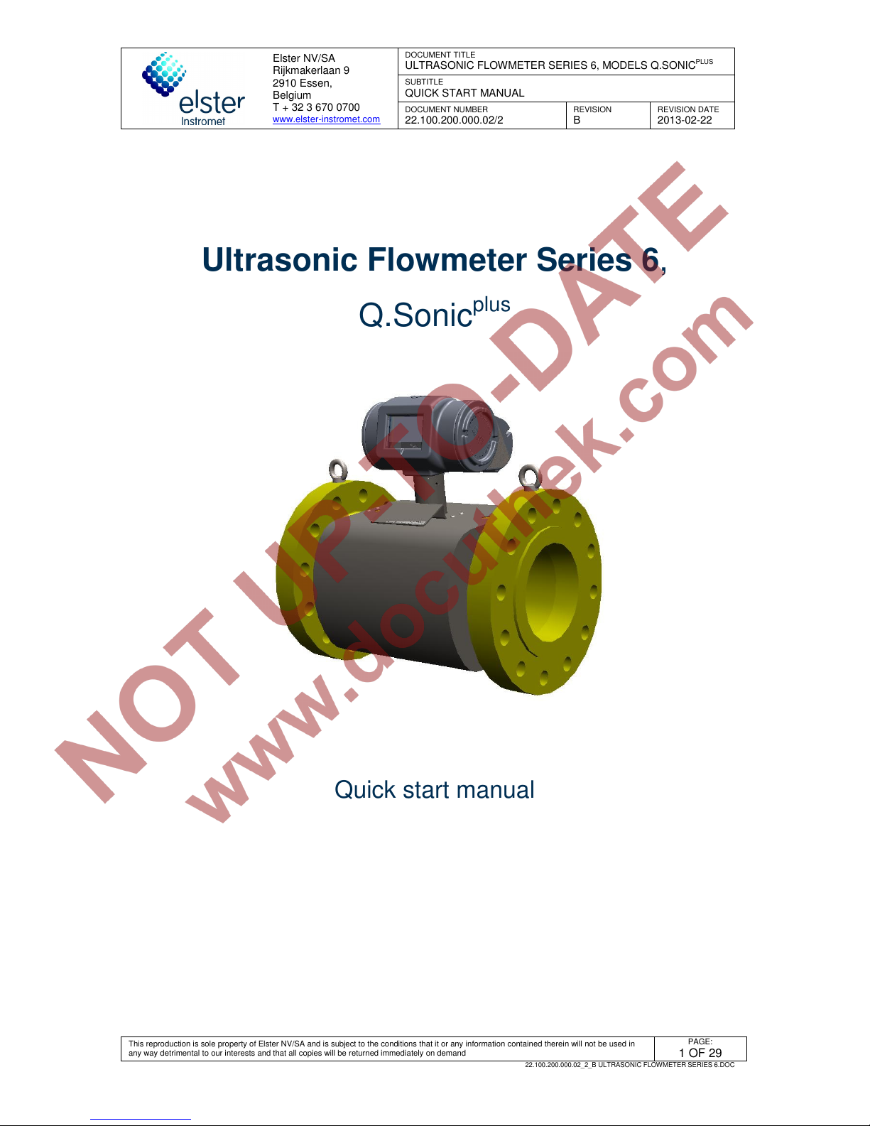
Ultrasonic Flowmeter Series 6,
Q.Sonic
plus
Quick start manual
Page 2
Elster NV/SA
Rijkmakerlaan 9
2910 Essen,
Belgium
T + 32 3 670 0700
www.elster-instromet.com
DOCUMENT TITLE
ULTRASONIC FLOWMETER SERIES 6, MODELS Q.SONIC
PLUS
SUBTITLE
QUICK START MANUAL
DOCUMENT NUMBER
22.100.200.000.02/2
REVISION
B
REVISION DATE
2013-02-22
This reproduction is sole property of Elster NV/SA and is subject to the conditions that it or any information contained therein will not be used in any way
detrimental to our interests and that all copies will be returned immediately on demand
PAGE
2 OF 29
22.100.200.000.02_2_B ULTRASONIC FLOWMETER SERIES 6.DOC
Table of contents
1
About this technical documentation .......................................................................................... 4
1.1 Introduction ........................................................................................................................ 4
1.2 Warranty ............................................................................................................................. 4
1.3 Typographical Conventions ............................................................................................. 5
1.4 Abbreviations ..................................................................................................................... 5
2
Ultrasonic Flowmeter Series 6 gas flow meter ......................................................................... 6
2.1 General ............................................................................................................................... 6
2.2 Applicable standards ........................................................................................................ 6
2.3 Configuration ..................................................................................................................... 6
2.4 Calibration .......................................................................................................................... 7
3
Theory of operation ..................................................................................................................... 8
3.1 Flow velocity measurement .............................................................................................. 8
3.2 Correction after calibration .............................................................................................. 9
3.3 Volume flow at line conditions ......................................................................................... 9
4
System description .................................................................................................................... 10
4.1 Flow cell ............................................................................................................................ 10
4.2 Signal processing unit .................................................................................................... 10
4.3 Transducers ..................................................................................................................... 11
4.4 Flow cell optional pressure sensor ............................................................................... 11
4.5 Flow cell optional temperature sensor .......................................................................... 12
4.6 Labels and nameplates ................................................................................................... 12
4.6.1. ATEX certified .................................................................................................................................. 12
4.6.2. IECEx certified ................................................................................................................................. 13
4.6.3. FM certified ...................................................................................................................................... 13
4.7 Sealing .............................................................................................................................. 15
4.7.1. Main plate ........................................................................................................................................ 15
4.7.2. SPU ................................................................................................................................................. 15
5
Installation and commissioning ............................................................................................... 17
5.1 Introduction ...................................................................................................................... 17
5.2 Installation requirements flow cell................................................................................. 17
5.2.1. Installing meter in pipeline ............................................................................................................... 17
5.2.2. Testing installation ........................................................................................................................... 18
5.3 Wiring instructions .......................................................................................................... 18
5.4 SPU configuration ........................................................................................................... 18
5.5 Cold commissioning ....................................................................................................... 18
5.6 Hot commissioning ......................................................................................................... 19
6
Operation .................................................................................................................................... 20
6.1 LED at display .................................................................................................................. 20
6.2 Front panel ....................................................................................................................... 21
6.2.1. Verifying software versions .............................................................................................................. 21
6.2.2. Display test ...................................................................................................................................... 22
Page 3
Elster NV/SA
Rijkmakerlaan 9
2910 Essen,
Belgium
T + 32 3 670 0700
www.elster-instromet.com
DOCUMENT TITLE
ULTRASONIC FLOWMETER SERIES 6, MODELS Q.SONIC
PLUS
SUBTITLE
QUICK START MANUAL
DOCUMENT NUMBER
22.100.200.000.02/2
REVISION
B
REVISION DATE
2013-02-22
This reproduction is sole property of Elster NV/SA and is subject to the conditions that it or any information contained therein will not be used in any way
detrimental to our interests and that all copies will be returned immediately on demand
PAGE
3 OF 29
22.100.200.000.02_2_B ULTRASONIC FLOWMETER SERIES 6.DOC
6.2.3. Checking errors and warnings ......................................................................................................... 23
6.3 Software package ............................................................................................................ 23
7
Maintenance, service and repair .............................................................................................. 24
7.1 Introduction ...................................................................................................................... 24
7.2 Exchanging components ................................................................................................ 24
7.2.1. Pressure sensors exchange ............................................................................................................ 24
7.2.2. Temperature sensors exchange ...................................................................................................... 25
7.2.3. Transducer exchange ...................................................................................................................... 25
7.2.4. SPU exchange ................................................................................................................................. 25
8
Storage and shipping ................................................................................................................ 27
9
MID requirements ....................................................................................................................... 28
9.1 General ............................................................................................................................. 28
9.2 EC declaration of conformity ......................................................................................... 28
9.3 Sealing .............................................................................................................................. 28
9.4 Calibration ........................................................................................................................ 28
9.5 Installation requirements ................................................................................................ 28
Appendix I. References ....................................................................................................................... 29
Figures
Figure 1: Path types ................................................................................................................................ 6
Figure 2: path layout Q.Sonic
plus
............................................................................................................. 7
Figure 3: Ultrasonic measuring line ........................................................................................................ 8
Figure 4: Example of an Elster-Instromet Ultrasonic gas flowmeter ..................................................... 10
Figure 5: SPU compartments ................................................................................................................ 11
Figure 6: SPU cover .............................................................................................................................. 11
Figure 7: NG transducer ........................................................................................................................ 11
Figure 8: NG transducer with the mounting bracket. ............................................................................ 11
Figure 9: example main plate ................................................................................................................ 12
Figure 10: example ATEX label ............................................................................................................ 13
Figure 11: example IECEx label ........................................................................................................... 13
Figure 12: example FM label................................................................................................................. 14
Figure 13: sealing main plate ................................................................................................................ 15
Figure 14: Example PCB sealing bracket ............................................................................................. 15
Figure 15: hardware protection on the main board ............................................................................... 16
Figure 17: LED at display ...................................................................................................................... 21
Figure 18: Front panel ........................................................................................................................... 21
Figure 19: checking software versions and checksum through the front panel .................................... 22
Figure 20: Display test .......................................................................................................................... 22
Figure 21: Errors / Warnings ................................................................................................................. 23
Tables
Table 1: Power LED .............................................................................................................................. 20
Table 2: Status LED .............................................................................................................................. 20
Page 4
Elster NV/SA
Rijkmakerlaan 9
2910 Essen,
Belgium
T + 32 3 670 0700
www.elster-instromet.com
DOCUMENT TITLE
ULTRASONIC FLOWMETER SERIES 6, MODELS Q.SONIC
PLUS
SUBTITLE
QUICK START MANUAL
DOCUMENT NUMBER
22.100.200.000.02/2
REVISION
B
REVISION DATE
2013-02-22
This reproduction is sole property of Elster NV/SA and is subject to the conditions that it or any information contained therein will not be used in any way
detrimental to our interests and that all copies will be returned immediately on demand
PAGE
4 OF 29
22.100.200.000.02_2_B ULTRASONIC FLOWMETER SERIES 6.DOC
1 About this technical documentation
1.1 Introduction
This manual is a quick guide to the operation and maintenance of the Ultrasonic Flowmeter
Series 6 gas flow meter, models Q.Sonic
plus
. This manual together with
22.100.200.001.02/2, Ultrasonic Flowmeter Series 6 Safety Instructions and
03.302.101.003.07/2, Ultrasonic Flowmeter Series 6 wiring instructions describes essential
information for safe use in compliance with and insofar applicable:
- European Directives (e.g. ATEX, PED, EMC, MID).
- International IECEx standards.
- North American FM Approvals standards.
- Canadian CSA standards (pending).
In this manual is explained how to verify from the labelling on your ultrasonic flowmeter to
which certifications it complies.
The manual also contains important instructions to prevent accidents and serious damage
before start-up, during operation, and to ensure trouble-free operation in the safest possible
way. Before using the product read this manual carefully, familiarise yourself with the
operation of the product, and strictly follow the instructions.
If you have any questions, or need further details of specific matters concerning this
product, please do not hesitate to contact one of our staff members, email: sales@elster-
instromet.com (See the address information on header).
This manual is based on the latest information. It is provided subject to alterations. We
reserve the right to change the construction and/or configuration of our products at any time
without obligation to update previously shipped equipment.
1.2 Warranty
The warranty provisions stipulated in the manufacturer's Terms of Delivery are applicable
to the product. The manufacturer shall have no obligation in the event that:
Repair or replacement of equipment or parts has been required through normal wear
and tear, or by necessity in whole or part by catastrophe, or the fault or negligence of
the purchaser.
The equipment, or parts, have been maintained or repaired by other than an authorised
representative of the manufacturer, or have been modified in any manner without prior
express written permission of the manufacturer.
Non-original parts are used.
Equipment is used improperly, incorrectly, carelessly or not in line with its nature and/or
purpose.
The product is used with unauthorised equipment or peripherals, including, but not
necessarily limited to, cables, testing equipment, computers, voltage, etc.
Page 5
Elster NV/SA
Rijkmakerlaan 9
2910 Essen,
Belgium
T + 32 3 670 0700
www.elster-instromet.com
DOCUMENT TITLE
ULTRASONIC FLOWMETER SERIES 6, MODELS Q.SONIC
PLUS
SUBTITLE
QUICK START MANUAL
DOCUMENT NUMBER
22.100.200.000.02/2
REVISION
B
REVISION DATE
2013-02-22
This reproduction is sole property of Elster NV/SA and is subject to the conditions that it or any information contained therein will not be used in any way
detrimental to our interests and that all copies will be returned immediately on demand
PAGE
5 OF 29
22.100.200.000.02_2_B ULTRASONIC FLOWMETER SERIES 6.DOC
The manufacturer is not responsible for the incidental or consequential damages resulting
from the breach of any express or implied warranties, including damage to property, and to
the extent permitted by law, damage for personal injury.
1.3 Typographical Conventions
This manual employs consistent visual cues and some standard text formats to help you
locate and interpret information easily.
Warning!
A warning indicates hazards or unsafe practices that could result
in severe personal injury or death.
Caution!
A caution indicates hazards or unsafe practices that could result
in minor personal injury or product or property damage.
A caution is also used to indicate operations or practices that
may cause the product to operate in an undefined or unexpected
way, or may produce non-specification results.
1.4 Abbreviations
ATEX Atmosphères Explosibles; European Directive 94/9/EC on equipment
and protective systems intended for use in potentially explosive
atmospheres
CSA Canadian Standards Association
DC Direct Current
EC European Community
EMC ElectroMagnetic Compatibility; European EMC Directive 2004/108/EC
IECEx International Electrotechnical Commission System for Certification to
Standards Relating to Equipment for use in Explosive Atmospheres
FM Factory Mutual Approvals
MID European Directive 2004/22/EC on measuring instruments
NMi Nederlands Meetinstituut
PED Pressure Equipment Directive; European Directive 97/23/EC concerning
pressure equipment
PC Personal Computer
PCB Printed Circuit Board
SPU Signal Processing Unit
UFM Ultrasonic FlowMeter
Page 6
Elster NV/SA
Rijkmakerlaan 9
2910 Essen,
Belgium
T + 32 3 670 0700
www.elster-instromet.com
DOCUMENT TITLE
ULTRASONIC FLOWMETER SERIES 6, MODELS Q.SONIC
PLUS
SUBTITLE
QUICK START MANUAL
DOCUMENT NUMBER
22.100.200.000.02/2
REVISION
B
REVISION DATE
2013-02-22
This reproduction is sole property of Elster NV/SA and is subject to the conditions that it or any information contained therein will not be used in any way
detrimental to our interests and that all copies will be returned immediately on demand
PAGE
6 OF 29
22.100.200.000.02_2_B ULTRASONIC FLOWMETER SERIES 6.DOC
2 Ultrasonic Flowmeter Series 6 gas flow meter
2.1 General
The Ultrasonic Flowmeter Series 6 is a sophisticated, multi-path ultrasonic gas flow meter
manufactured by Elster NV/SA. It has been specifically designed for custody transfer
measuring applications that demand a high degree of accuracy and reliability.
2.2 Applicable standards
The Ultrasonic Flowmeter Series 6 is manufactured to be in accordance with European
Directives: ATEX, PED, EMC and optionally MID.
If the meter is ordered for use at a location where European Directives are NOT mandatory,
the meter can alternatively be manufactured with IECEx or FM approval for use in
hazardous area.
2.3 Configuration
On the flow cell of an Ultrasonic Flowmeter Series 6 several pairs of transducers are
mounted. Each pair of transducers represents one individual measuring path. There are two
measuring path types on the Ultrasonic Flowmeter Series 6: Axial (single bounce) and swirl
(double bounce) these are shown in Figure 1.
Figure 1: Path types
The Q.Sonic
plus
path layout consists of 2 axial paths and 4 swirl paths. This combination
results in a complete symmetrical path layout, ensuring the most optimal accuracy. Figure 2
shows the path layout of the Q.Sonic
plus
.
Page 7
Elster NV/SA
Rijkmakerlaan 9
2910 Essen,
Belgium
T + 32 3 670 0700
www.elster-instromet.com
DOCUMENT TITLE
ULTRASONIC FLOWMETER SERIES 6, MODELS Q.SONIC
PLUS
SUBTITLE
QUICK START MANUAL
DOCUMENT NUMBER
22.100.200.000.02/2
REVISION
B
REVISION DATE
2013-02-22
This reproduction is sole property of Elster NV/SA and is subject to the conditions that it or any information contained therein will not be used in any way
detrimental to our interests and that all copies will be returned immediately on demand
PAGE
7 OF 29
22.100.200.000.02_2_B ULTRASONIC FLOWMETER SERIES 6.DOC
Figure 2: path layout Q.Sonic
plus
2.4 Calibration
When using the Ultrasonic Flowmeter Series 6, model Q.Sonic
plus
in custody transfer
applications, most countries demand (by law) a calibration from a certified calibration
institute, supervised by an inspector of weights and measures. Examples of facilities
generally used for calibrations are Euroloop in Rotterdam (NL), TransCanada Calibrations
in Canada and PIGSAR GH45 of E.ON Ruhrgas AG in Dorsten (D).
If the Q.Sonic Series 6 has to be in accordance with MID, extra restrictions should be taken
into account (see chapter 9.4).
Page 8
Elster NV/SA
Rijkmakerlaan 9
2910 Essen,
Belgium
T + 32 3 670 0700
www.elster-instromet.com
DOCUMENT TITLE
ULTRASONIC FLOWMETER SERIES 6, MODELS Q.SONIC
PLUS
SUBTITLE
QUICK START MANUAL
DOCUMENT NUMBER
22.100.200.000.02/2
REVISION
B
REVISION DATE
2013-02-22
This reproduction is sole property of Elster NV/SA and is subject to the conditions that it or any information contained therein will not be used in any way
detrimental to our interests and that all copies will be returned immediately on demand
PAGE
8 OF 29
22.100.200.000.02_2_B ULTRASONIC FLOWMETER SERIES 6.DOC
3 Theory of operation
An ultrasonic flow meter is an inferential measurement device that consists of ultrasonic
transducers that are typically located along a pipe's wall. The transducers are inserted into the
piping using a gas tight mechanism. Ultrasonic pulses are alternately transmitted by one
transducer and received by the other one. Figure 3 shows a simple geometry of two transducers,
‘A’ and ‘B’, at a sharp angle “ϕ” with respect to the axis of a straight cylindrical pipe with diameter
“D”. The Q.Sonic Series 6 employs reflection paths, where the acoustic pulses reflect one or more
times off the pipe wall.
v
B
A
L
D
ϕ
Figure 3: Ultrasonic measuring line
3.1 Flow velocity measurement
The acoustic pulses are crossing the pipe like a ferryman crossing a river. Without flow,
they propagate with the same speed in both directions. If the gas in the pipe has a flow
velocity different from zero, pulses travelling downstream with the flow will move faster,
while those travelling upstream against the flow will move slower. Thus, the downstream
travel times “tab“ will be shorter, while the upstream ones “tba“ will be longer as compared
when the gas is not moving. Equation 1 illustrates the computation of these times:
( )
−⋅
⋅
=
nnn
n
raw
tbatab
L
VoG
n
11
cos2
ϕ
Equation 1: raw gas velocity
where:
t
abn
the downstream travel time of path n.
t
ban
the upstream travel time of path n.
Ln the straight line length of the acoustic path between the two transducers.
VoGraw is the average uncorrected (raw) gas velocity.
ϕn the angle between the gas flow and ultrasonic signal.
The raw gas velocity is corrected by a Reynolds flow profile correction. This correction is
depending on the path type. Also the contribution of the gas velocity of each path to the
combined gas velocity is depending on the path type.
Page 9
Elster NV/SA
Rijkmakerlaan 9
2910 Essen,
Belgium
T + 32 3 670 0700
www.elster-instromet.com
DOCUMENT TITLE
ULTRASONIC FLOWMETER SERIES 6, MODELS Q.SONIC
PLUS
SUBTITLE
QUICK START MANUAL
DOCUMENT NUMBER
22.100.200.000.02/2
REVISION
B
REVISION DATE
2013-02-22
This reproduction is sole property of Elster NV/SA and is subject to the conditions that it or any information contained therein will not be used in any way
detrimental to our interests and that all copies will be returned immediately on demand
PAGE
9 OF 29
22.100.200.000.02_2_B ULTRASONIC FLOWMETER SERIES 6.DOC
3.2 Correction after calibration
After flow calibration the meter can be adjusted either through an adjust factor or through
linearization. How the meter is adjusted can be visualized at the display (see chapter 6.1).
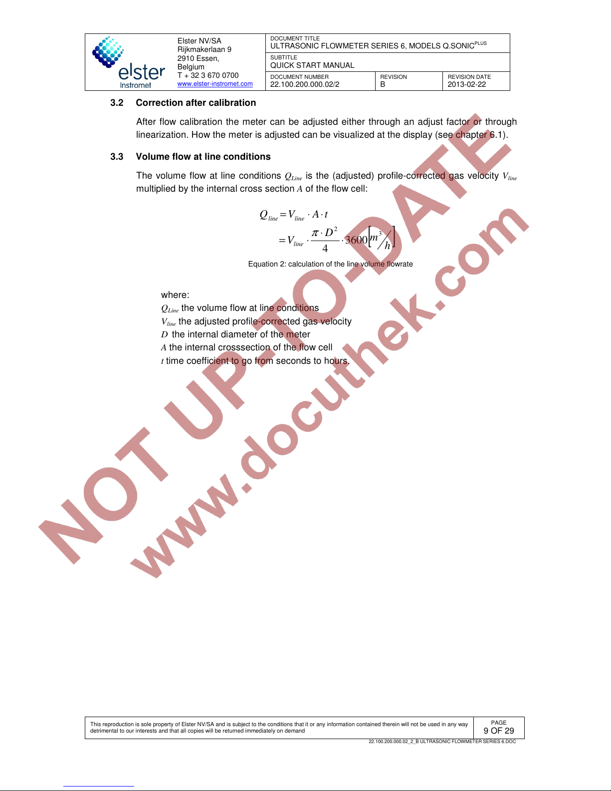
3.3 Volume flow at line conditions
The volume flow at line conditions Q
Line
is the (adjusted) profile-corrected gas velocity V
line
multiplied by the internal cross section A of the flow cell:
[
]
h
m
D
V
tAVQ
line
lineline
3
2
3600
4
⋅
⋅
⋅=
⋅⋅=
π
Equation 2: calculation of the line volume flowrate
where:
Q
Line
the volume flow at line conditions
V
line
the adjusted profile-corrected gas velocity
D the internal diameter of the meter
A the internal crosssection of the flow cell
t time coefficient to go from seconds to hours.
Page 10
Elster NV/SA
Rijkmakerlaan 9
2910 Essen,
Belgium
T + 32 3 670 0700
www.elster-instromet.com
DOCUMENT TITLE
ULTRASONIC FLOWMETER SERIES 6, MODELS Q.SONIC
PLUS
SUBTITLE
QUICK START MANUAL
DOCUMENT NUMBER
22.100.200.000.02/2
REVISION
B
REVISION DATE
2013-02-22
This reproduction is sole property of Elster NV/SA and is subject to the conditions that it or any information contained therein will not be used in any way
detrimental to our interests and that all copies will be returned immediately on demand
PAGE
10 OF 29
22.100.200.000.02_2_B ULTRASONIC FLOWMETER SERIES 6.DOC
4 System description
4.1 Flow cell
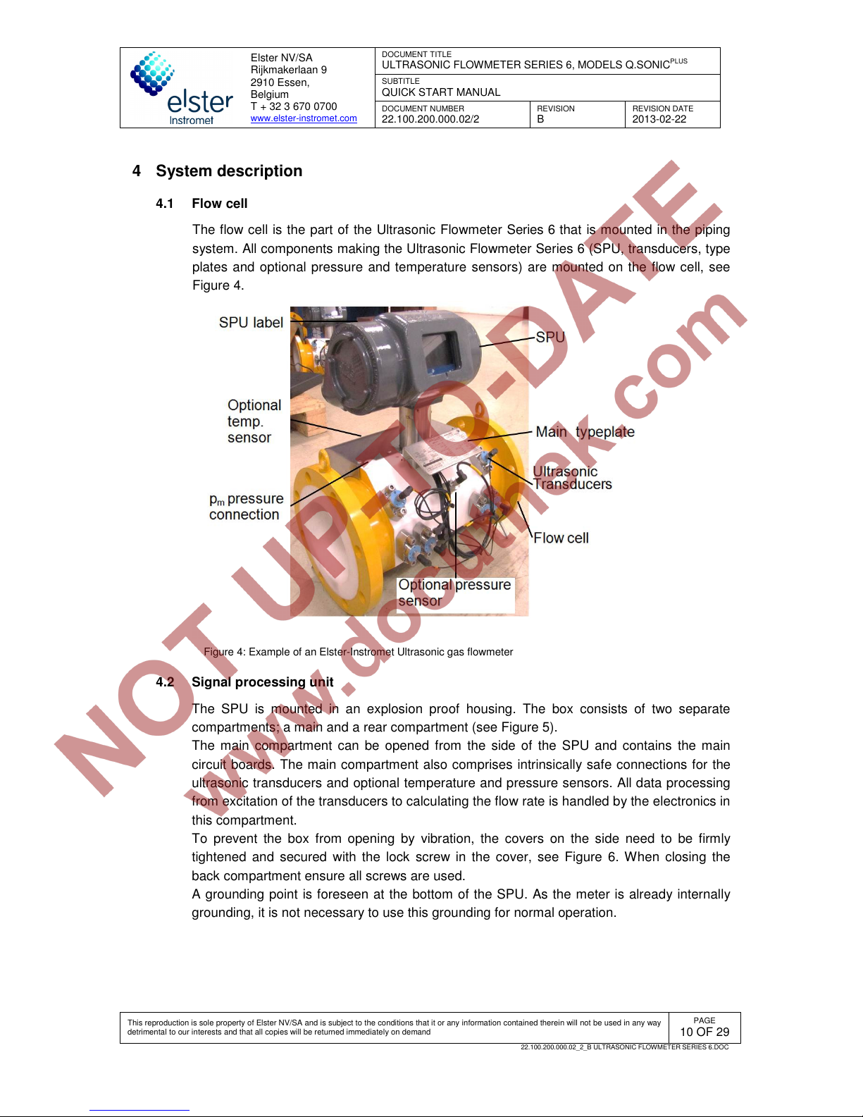
The flow cell is the part of the Ultrasonic Flowmeter Series 6 that is mounted in the piping
system. All components making the Ultrasonic Flowmeter Series 6 (SPU, transducers, type
plates and optional pressure and temperature sensors) are mounted on the flow cell, see
Figure 4.
Figure 4: Example of an Elster-Instromet Ultrasonic gas flowmeter
4.2 Signal processing unit
The SPU is mounted in an explosion proof housing. The box consists of two separate
compartments; a main and a rear compartment (see Figure 5).
The main compartment can be opened from the side of the SPU and contains the main
circuit boards. The main compartment also comprises intrinsically safe connections for the
ultrasonic transducers and optional temperature and pressure sensors. All data processing
from excitation of the transducers to calculating the flow rate is handled by the electronics in
this compartment.
To prevent the box from opening by vibration, the covers on the side need to be firmly
tightened and secured with the lock screw in the cover, see Figure 6. When closing the
back compartment ensure all screws are used.
A grounding point is foreseen at the bottom of the SPU. As the meter is already internally
grounding, it is not necessary to use this grounding for normal operation.
Page 11

Elster NV/SA
Rijkmakerlaan 9
2910 Essen,
Belgium
T + 32 3 670 0700
www.elster-instromet.com
DOCUMENT TITLE
ULTRASONIC FLOWMETER SERIES 6, MODELS Q.SONIC
PLUS
SUBTITLE
QUICK START MANUAL
DOCUMENT NUMBER
22.100.200.000.02/2
REVISION
B
REVISION DATE
2013-02-22
This reproduction is sole property of Elster NV/SA and is subject to the conditions that it or any information contained therein will not be used in any way
detrimental to our interests and that all copies will be returned immediately on demand
PAGE
11 OF 29
22.100.200.000.02_2_B ULTRASONIC FLOWMETER SERIES 6.DOC
Figure 5: SPU compartments
Figure 6: SPU cover
The rear compartment comprises a field terminal board used for connecting the Ultrasonic
Flowmeter Series 6 to the end users applications. For detailed information about this see
chapter 5.2.2.
4.3 Transducers
The ultrasonic signals required for the flow measurement are generated and received by
ultrasonic transducers.
Piezoelectric transducers employ crystals or ceramics that are set into vibration when an
alternating voltage is applied to the piezoelectric element. The vibrating element generates
sound waves in the gas. Since the piezoelectric effect is reversible, the element will
become electrically polarised and produce voltages related to the mechanical strain, when
the crystal is distorted by the action of incident sound waves. Because the acoustic
impedance of the gas is much smaller compared to the acoustic impedance of the
piezoelectric element, and to maximise the acoustic efficiency, a matching layer is
employed between the gas and the piezoelectric element.
The transducers used in the Ultrasonic Flowmeter Series 6 are type ‘NG’, see Figure 7.
Figure 8 visualises the NG transducer with the mounting bracket.
Figure 7: NG transducer
Figure 8: NG transducer with the mounting bracket.
4.4 Flow cell optional pressure sensor
As an optional feature the UFM can be equipped with a pressure sensor. This pressure
sensor is used for:
Page 12
Elster NV/SA
Rijkmakerlaan 9
2910 Essen,
Belgium
T + 32 3 670 0700
www.elster-instromet.com
DOCUMENT TITLE
ULTRASONIC FLOWMETER SERIES 6, MODELS Q.SONIC
PLUS
SUBTITLE
QUICK START MANUAL
DOCUMENT NUMBER
22.100.200.000.02/2
REVISION
B
REVISION DATE
2013-02-22
This reproduction is sole property of Elster NV/SA and is subject to the conditions that it or any information contained therein will not be used in any way
detrimental to our interests and that all copies will be returned immediately on demand
PAGE
12 OF 29
22.100.200.000.02_2_B ULTRASONIC FLOWMETER SERIES 6.DOC
• Reynolds flow profile correction
• Compensation of the flow cell expansion due to gas pressure
Caution!
The pressure sensor is not used for Volume conversion
4.5 Flow cell optional temperature sensor
As an optional feature the UFM can be equipped with a temperature sensor. The
temperature sensor is used for:
• The Reynolds flow profile correction
• Compensation of the flow cell expansion due to flow cell temperature
Caution!.
The temperature sensor is not used for volume conversion.
4.6 Labels and nameplates
Nameplates and labels are used to identify the product and to provide details on the
specific product. Together with the product manual it specifies how the product is certified
and designed.
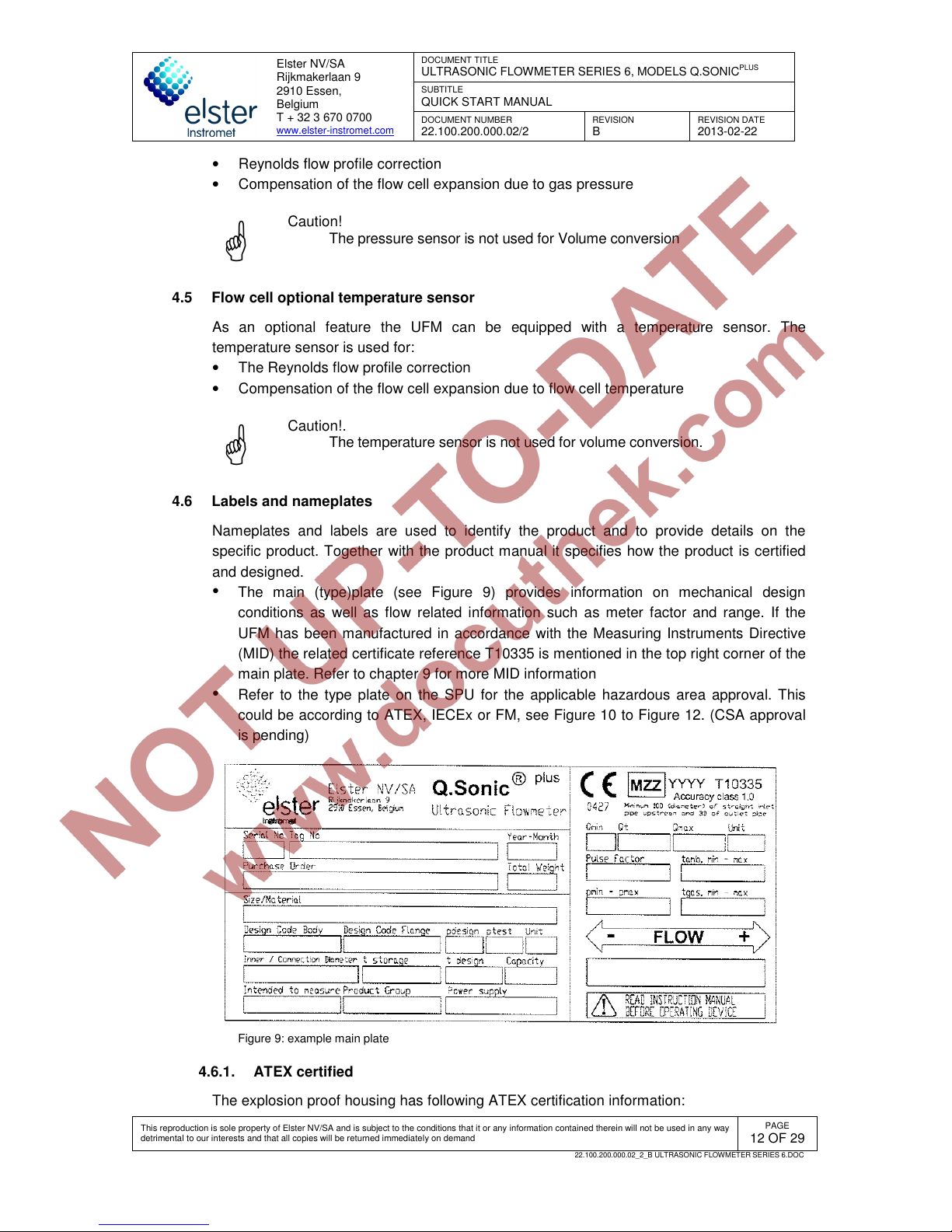
The main (type)plate (see Figure 9) provides information on mechanical design
conditions as well as flow related information such as meter factor and range. If the
UFM has been manufactured in accordance with the Measuring Instruments Directive
(MID) the related certificate reference T10335 is mentioned in the top right corner of the
main plate. Refer to chapter 9 for more MID information
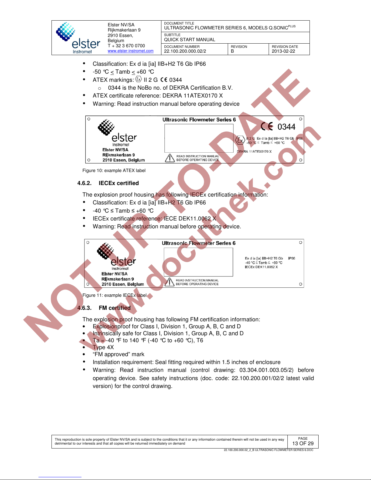
Refer to the type plate on the SPU for the applicable hazardous area approval. This
could be according to ATEX, IECEx or FM, see Figure 10 to Figure 12. (CSA approval
is pending)
Figure 9: example main plate
4.6.1. ATEX certified
The explosion proof housing has following ATEX certification information:
Page 13
Elster NV/SA
Rijkmakerlaan 9
2910 Essen,
Belgium
T + 32 3 670 0700
www.elster-instromet.com
DOCUMENT TITLE
ULTRASONIC FLOWMETER SERIES 6, MODELS Q.SONIC
PLUS
SUBTITLE
QUICK START MANUAL
DOCUMENT NUMBER
22.100.200.000.02/2
REVISION
B
REVISION DATE
2013-02-22
This reproduction is sole property of Elster NV/SA and is subject to the conditions that it or any information contained therein will not be used in any way
detrimental to our interests and that all copies will be returned immediately on demand
PAGE
13 OF 29
22.100.200.000.02_2_B ULTRASONIC FLOWMETER SERIES 6.DOC
Classification: Ex d ia [ia] IIB+H2 T6 Gb IP66
-50 °C < Tamb < +60 °C
ATEX markings: II 2 G 0344
o 0344 is the NoBo no. of DEKRA Certification B.V.
ATEX certificate reference: DEKRA 11ATEX0170 X
Warning: Read instruction manual before operating device
Figure 10: example ATEX label
4.6.2. IECEx certified
The explosion proof housing has following IECEx certification information:
Classification: Ex d ia [ia] IIB+H2 T6 Gb IP66
-40 °C ≤ Tamb ≤ +60 °C
IECEx certificate reference: IECE DEK11.0062 X
Warning: Read instruction manual before operating device.
Figure 11: example IECEx label
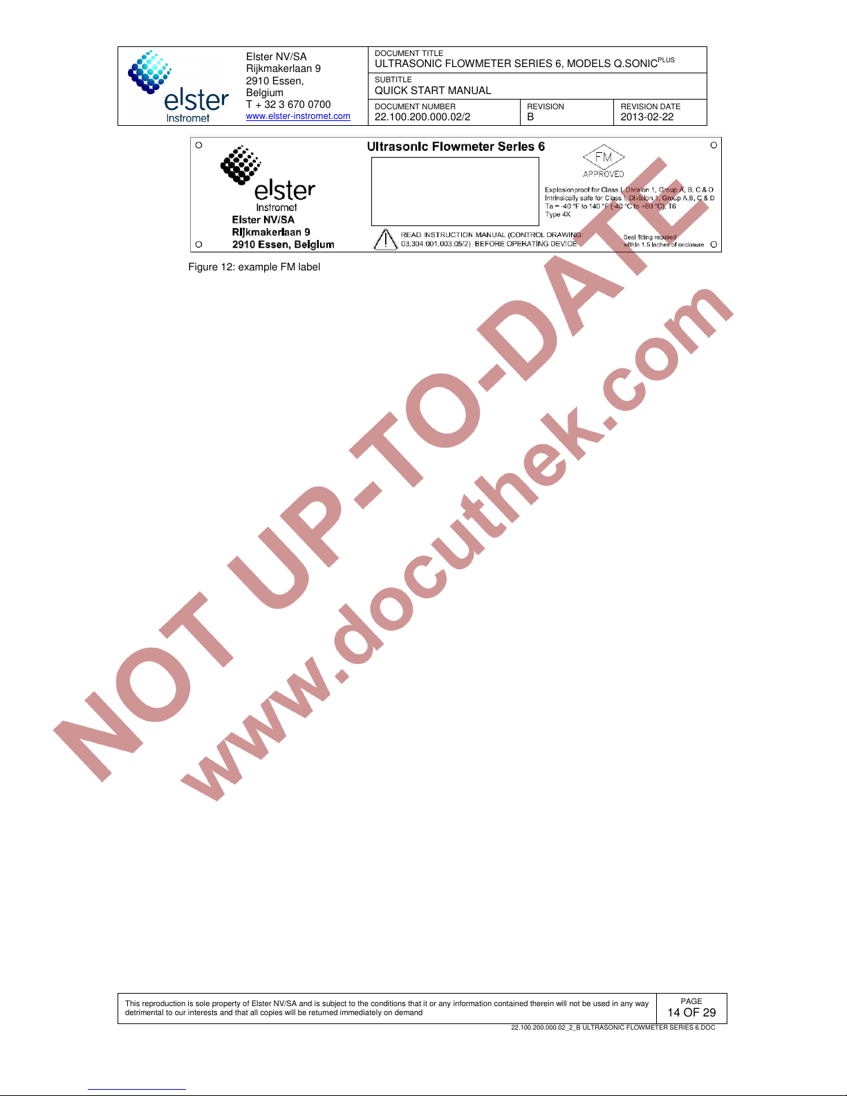
4.6.3. FM certified
The explosion proof housing has following FM certification information:
• Explosionproof for Class I, Division 1, Group A, B, C and D
• Intrinsically safe for Class I, Division 1, Group A, B, C and D
• Ta = -40 °F to 140 °F (-40 °C to +60 °C), T6
• Type 4X
• “FM approved” mark
Installation requirement: Seal fitting required within 1.5 inches of enclosure
Warning: Read instruction manual (control drawing: 03.304.001.003.05/2) before
operating device. See safety instructions (doc. code: 22.100.200.001/02/2 latest valid
version) for the control drawing.
Page 14
Elster NV/SA
Rijkmakerlaan 9
2910 Essen,
Belgium
T + 32 3 670 0700
www.elster-instromet.com
DOCUMENT TITLE
ULTRASONIC FLOWMETER SERIES 6, MODELS Q.SONIC
PLUS
SUBTITLE
QUICK START MANUAL
DOCUMENT NUMBER
22.100.200.000.02/2
REVISION
B
REVISION DATE
2013-02-22
This reproduction is sole property of Elster NV/SA and is subject to the conditions that it or any information contained therein will not be used in any way
detrimental to our interests and that all copies will be returned immediately on demand
PAGE
14 OF 29
22.100.200.000.02_2_B ULTRASONIC FLOWMETER SERIES 6.DOC
Figure 12: example FM label
Page 15
Elster NV/SA
Rijkmakerlaan 9
2910 Essen,
Belgium
T + 32 3 670 0700
www.elster-instromet.com
DOCUMENT TITLE
ULTRASONIC FLOWMETER SERIES 6, MODELS Q.SONIC
PLUS
SUBTITLE
QUICK START MANUAL
DOCUMENT NUMBER
22.100.200.000.02/2
REVISION
B
REVISION DATE
2013-02-22
This reproduction is sole property of Elster NV/SA and is subject to the conditions that it or any information contained therein will not be used in any way
detrimental to our interests and that all copies will be returned immediately on demand
PAGE
15 OF 29
22.100.200.000.02_2_B ULTRASONIC FLOWMETER SERIES 6.DOC
4.7 Sealing
This chapter describes the important sealing locations. This chapter describes the sealings
as required by MID certificate T10335 (see also chapter 9). Even if MID is not required it is
advised to seal the UFM.
4.7.1. Main plate
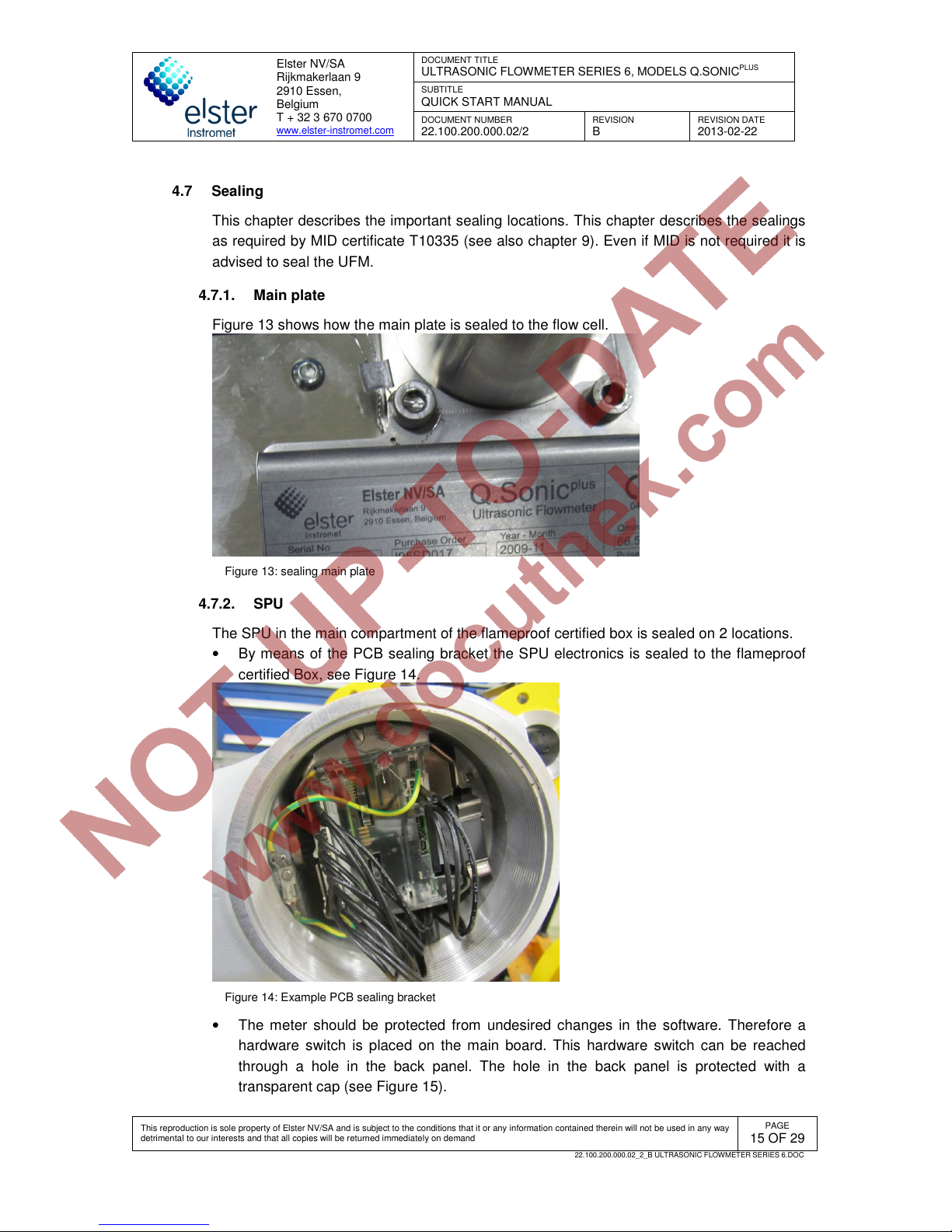
Figure 13 shows how the main plate is sealed to the flow cell.
Figure 13: sealing main plate
4.7.2. SPU
The SPU in the main compartment of the flameproof certified box is sealed on 2 locations.
• By means of the PCB sealing bracket the SPU electronics is sealed to the flameproof
certified Box, see Figure 14.
Figure 14: Example PCB sealing bracket
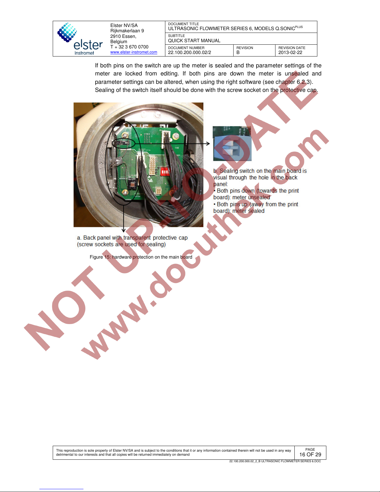
• The meter should be protected from undesired changes in the software. Therefore a
hardware switch is placed on the main board. This hardware switch can be reached
through a hole in the back panel. The hole in the back panel is protected with a
transparent cap (see Figure 15).
Page 16
Elster NV/SA
Rijkmakerlaan 9
2910 Essen,
Belgium
T + 32 3 670 0700
www.elster-instromet.com
DOCUMENT TITLE
ULTRASONIC FLOWMETER SERIES 6, MODELS Q.SONIC
PLUS
SUBTITLE
QUICK START MANUAL
DOCUMENT NUMBER
22.100.200.000.02/2
REVISION
B
REVISION DATE
2013-02-22
This reproduction is sole property of Elster NV/SA and is subject to the conditions that it or any information contained therein will not be used in any way
detrimental to our interests and that all copies will be returned immediately on demand
PAGE
16 OF 29
22.100.200.000.02_2_B ULTRASONIC FLOWMETER SERIES 6.DOC
If both pins on the switch are up the meter is sealed and the parameter settings of the
meter are locked from editing. If both pins are down the meter is unsealed and
parameter settings can be altered, when using the right software (see chapter 6.2.3).
Sealing of the switch itself should be done with the screw socket on the protective cap.
Figure 15: hardware protection on the main board
Page 17
Elster NV/SA
Rijkmakerlaan 9
2910 Essen,
Belgium
T + 32 3 670 0700
www.elster-instromet.com
DOCUMENT TITLE
ULTRASONIC FLOWMETER SERIES 6, MODELS Q.SONIC
PLUS
SUBTITLE
QUICK START MANUAL
DOCUMENT NUMBER
22.100.200.000.02/2
REVISION
B
REVISION DATE
2013-02-22
This reproduction is sole property of Elster NV/SA and is subject to the conditions that it or any information contained therein will not be used in any way
detrimental to our interests and that all copies will be returned immediately on demand
PAGE
17 OF 29
22.100.200.000.02_2_B ULTRASONIC FLOWMETER SERIES 6.DOC
5 Installation and commissioning
5.1 Introduction
It is very important to check the shipment of your ultrasonic flow meter equipment. At least
a visual inspection of surfaces and flanges should be performed. In case of damage,
contact Elster NV/SA immediately.
Also verify if all the necessary documentation is available as well. At least you should have:
• Safety instructions (doc. Code: 22.100.200.001.02/2 latest valid version)
• Operation and maintenance manual (doc. Code: 22.100.200.002.02/2 latest valid
revision)
Also look at your project data to see if extra documentation is required and delivered. If
documentation is missing, contact Elster NV/SA or your local agent immediately.
5.2 Installation requirements flow cell
5.2.1. Installing meter in pipeline
The Ultrasonic Flowmeter Series 6 (flow cell, transducers and SPU) is shipped in a suitable
box (e.g. wooden box, cardboard box, …). Carefully disassemble the box. Remove the
transport straps from the flow cell, and then move the ultrasonic flow meter (using the lifting
lugs provided on the flow cell) to the installation site. Install the meter according to end-
user’s company regulations and applicable local and national requirements. To ensure
optimal performance of the UFM, comply with the up- and downstream spool requirements
specified for your particular UFM (see your order documentation).
Warning!
To avoid possible injury, make sure the lifting equipment is suitable
for the weight of the Ultrasonic Flowmeter Series 6. Always use the
lifting lugs and make sure lifting equipment is certified and shows
no damage or wear.
Be aware!
• Special attention needs to be taken when the Ultrasonic
Flowmeter Series 6 has to be installed in accordance with MID
(see chapter 9.5).
• For FM Approved Ultrasonic Flowmeter see also the Control
drawing and installation remarks in the Safety instructions (doc.
Code: 22.100.200.001.02/2 latest valid version).
Page 18
Elster NV/SA
Rijkmakerlaan 9
2910 Essen,
Belgium
T + 32 3 670 0700
www.elster-instromet.com
DOCUMENT TITLE
ULTRASONIC FLOWMETER SERIES 6, MODELS Q.SONIC
PLUS
SUBTITLE
QUICK START MANUAL
DOCUMENT NUMBER
22.100.200.000.02/2
REVISION
B
REVISION DATE
2013-02-22
This reproduction is sole property of Elster NV/SA and is subject to the conditions that it or any information contained therein will not be used in any way
detrimental to our interests and that all copies will be returned immediately on demand
PAGE
18 OF 29
22.100.200.000.02_2_B ULTRASONIC FLOWMETER SERIES 6.DOC
5.2.2. Testing installation
The flowcell is always hydrotested in-house at the correct hydrotest pressure before the
transducers were installed on the ultrasonic flowmeter. Herewith all welding of the flowcell is
checked. When an Ultrasonic flowmeter series 6 is installed in a pipe line, it is no longer
possible to hydrotest the pipeline. Water can be trapped between the housing and the
transducers, causing the meter to have difficulties measuring.
Before pressurizing check all pressure points on the meter. If necessary remove the cover
caps to have a clear view of the entire pressure point, particularly when an adapter is fitted
on the meter body.
5.3 Wiring instructions
All detailed information about wiring is stated the ‘Ultrasonic Flowmeter Series 6 Wiring
Instructions’ (document code 03.302.101.003.07/2), as well as Ultrasonic Flowmeter Series
6 Safety Instructions (document code 22.100.200.001.02/2). Please refer to these
documents for correct wiring of the Ultrasonic flowmeter series 6.
5.4 SPU configuration
When the meter is installed and correctly wired, it’s advisable to read out the parameter
settings of the meter. If the meter had been calibrated before, the parameter set-up should
be compared to the one of the calibration.
The parameter set-up can be read with the software package ‘SonicExplorer’. Connection
should be made through the Ethernet or DSL communication, more detailed information
about this matter can be found in the manual of the software packages. When mismatches
are detected; contact Elster NV/SA or your local representative immediately.
Warning!
When opening the SPU (either main – or rear compartment), obey the
rules and regulations that apply to hazardous area operations.
The electronics and the main plate of the UFM should be sealed. The sealing should be
done by either the calibration facility or by Elster NV/SA. This should be done according to
chapter 4.7; any mismatch has to be reported to Elster NV/SA or your local representative
immediately.
5.5 Cold commissioning
During cold commissioning the meter is pressurized with a known gas composition, at a
known temperature and pressure, because in some cases the UFM will not be able to
measure under atmospheric conditions.
A thorough functional test is performed by means of a PC and diagnostic software package
(‘SonicExplorer’). Diagnostics and status per measuring path and the zero flow can be
checked, assuming there is sufficient pressure in the meter. A technician of Elster NV/SA
will, if this has been agreed, verify measurements and check the system performance.
Page 19
Elster NV/SA
Rijkmakerlaan 9
2910 Essen,
Belgium
T + 32 3 670 0700
www.elster-instromet.com
DOCUMENT TITLE
ULTRASONIC FLOWMETER SERIES 6, MODELS Q.SONIC
PLUS
SUBTITLE
QUICK START MANUAL
DOCUMENT NUMBER
22.100.200.000.02/2
REVISION
B
REVISION DATE
2013-02-22
This reproduction is sole property of Elster NV/SA and is subject to the conditions that it or any information contained therein will not be used in any way
detrimental to our interests and that all copies will be returned immediately on demand
PAGE
19 OF 29
22.100.200.000.02_2_B ULTRASONIC FLOWMETER SERIES 6.DOC
5.6 Hot commissioning
The hot commissioning is in most cases the last test of the UFM and can be witnessed by a
representative of the client and, if required, by an inspector of weights and measures for the
official sealing. Under this condition there is process gas in the pipe and a flow test is being
performed. The performance, AGC Levels/Limits and zero flow are checked again. If
possible, the gas flow running through the UFM will be compared to another flowmeter in
the line. Most UFM are calibrated gas flow meters, so the measured value is reliable
without exception. Furthermore, the interaction with the flow computer can be tested.
Page 20
Elster NV/SA
Rijkmakerlaan 9
2910 Essen,
Belgium
T + 32 3 670 0700
www.elster-instromet.com
DOCUMENT TITLE
ULTRASONIC FLOWMETER SERIES 6, MODELS Q.SONIC
PLUS
SUBTITLE
QUICK START MANUAL
DOCUMENT NUMBER
22.100.200.000.02/2
REVISION
B
REVISION DATE
2013-02-22
This reproduction is sole property of Elster NV/SA and is subject to the conditions that it or any information contained therein will not be used in any way
detrimental to our interests and that all copies will be returned immediately on demand
PAGE
20 OF 29
22.100.200.000.02_2_B ULTRASONIC FLOWMETER SERIES 6.DOC
6 Operation
This chapter describes how the Ultrasonic Flowmeter Series 6 can be operated through the
interactive touch screen display on the meter. For more detail information, see the Q.Sonic Series 6
operation and maintenance manual (document code: 22.100.200.002.02/2 last valid revision).
6.1 LED at display
2 LED’s provide an overall status indication of the meter.
• Power LED (LED 1 at Figure 16):
LED status Description
Off Power off
Green Power on
Table 1: Power LED
• Status LED (LED 2 at Figure 16)
LED status Description
Off Power off or
The device is running warning and error free.
Yellow, flashing A warning is pending that does not affect the metrology
relevant functionalities. The user has to accept such
warnings at the operation panel before the color of the
status LED turns back to off*
Yellow, permanently
illuminated
At least one warning that does not affect the metrology
relevant functionalities was pending but has already ended.
The user has to accept such warnings at the operation
panel before the color of the status LED turns back to off*
Red, flashing An error is pending that affects the metrology relevant
functionalities. The user has to accept such warnings at the
operation panel before the color of the status LED turns
back to off*
Red, permanently
illuminated
At least one error that affects the metrology relevant
functionalities was pending but has already ended. The
user has to accept such warnings at the operation panel
before the color of the status LED turns back to off*
* See chapter 6.2.3
Table 2: Status LED
Page 21
Elster NV/SA
Rijkmakerlaan 9
2910 Essen,
Belgium
T + 32 3 670 0700
www.elster-instromet.com
DOCUMENT TITLE
ULTRASONIC FLOWMETER SERIES 6, MODELS Q.SONIC
PLUS
SUBTITLE
QUICK START MANUAL
DOCUMENT NUMBER
22.100.200.000.02/2
REVISION
B
REVISION DATE
2013-02-22
This reproduction is sole property of Elster NV/SA and is subject to the conditions that it or any information contained therein will not be used in any way
detrimental to our interests and that all copies will be returned immediately on demand
PAGE
21 OF 29
22.100.200.000.02_2_B ULTRASONIC FLOWMETER SERIES 6.DOC
Figure 16: LED at display
6.2 Front panel
The SPU contains an interactive touch screen display, showing the most important
measurements and diagnostics (line flow, gas velocity, speed of sound, totalizers, …). It
contains a touch screen with 7 touch area’s (see Figure 17).
It’s also possible to mimic the interactive touch screen display on your PC. To do this you
need to connect the ethernet cable at the field terminal board (see chapter 5.2.2). Go to the
internet browser of the PC and type following internet address: http://X/frontpanel.html
(where X stands for IP-address of the meter). The IP-address can be found through the
interactive touch screen display at ‘Info’, also see Figure 19.
Figure 17: Front panel
6.2.1. Verifying software versions
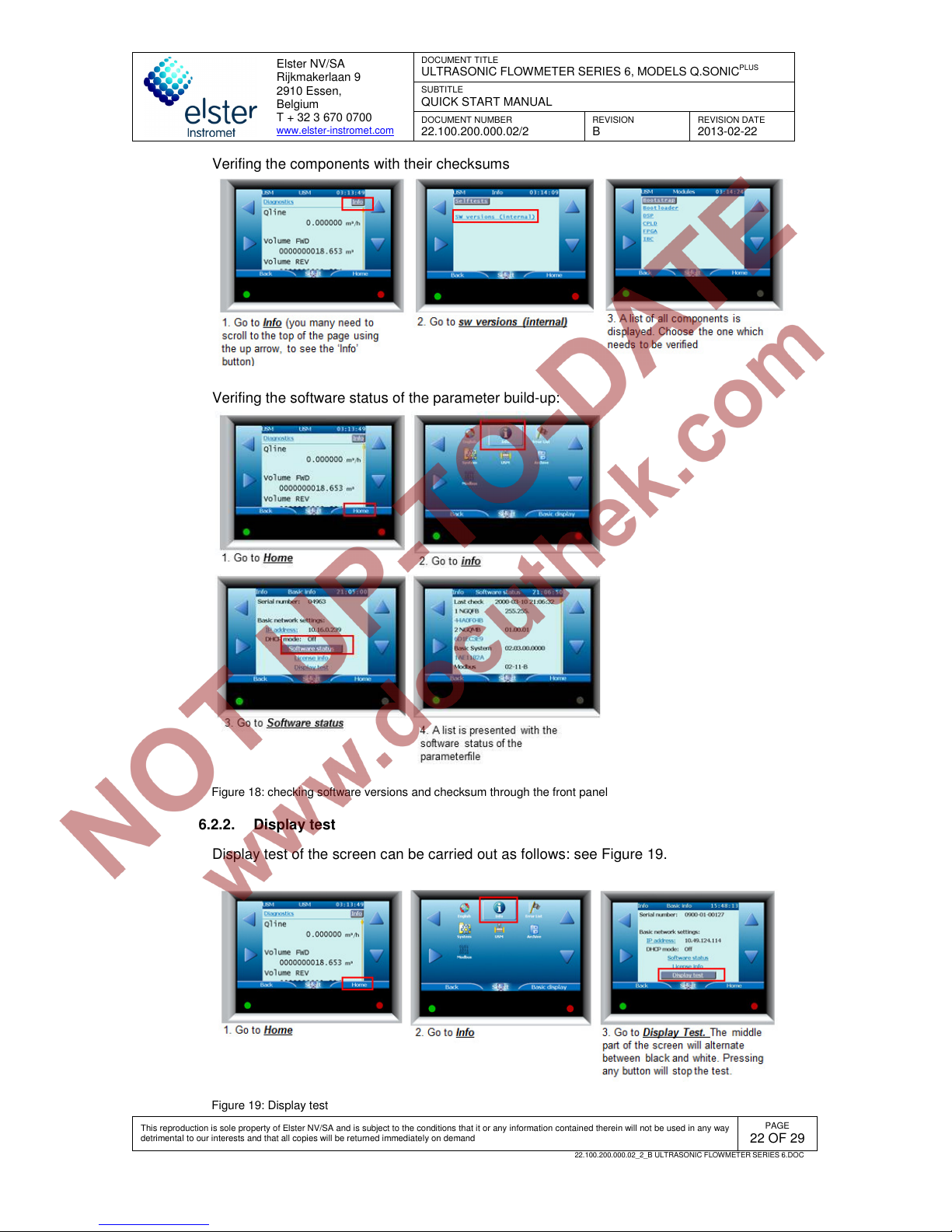
It is also possible to verify the software version with checksum for all components. This
should be done at 2 different places. Figure 18 shows how this should be done.
Page 22
Elster NV/SA
Rijkmakerlaan 9
2910 Essen,
Belgium
T + 32 3 670 0700
www.elster-instromet.com
DOCUMENT TITLE
ULTRASONIC FLOWMETER SERIES 6, MODELS Q.SONIC
PLUS
SUBTITLE
QUICK START MANUAL
DOCUMENT NUMBER
22.100.200.000.02/2
REVISION
B
REVISION DATE
2013-02-22
This reproduction is sole property of Elster NV/SA and is subject to the conditions that it or any information contained therein will not be used in any way
detrimental to our interests and that all copies will be returned immediately on demand
PAGE
22 OF 29
22.100.200.000.02_2_B ULTRASONIC FLOWMETER SERIES 6.DOC
Verifing the components with their checksums
Verifing the software status of the parameter build-up:
Figure 18: checking software versions and checksum through the front panel
6.2.2. Display test
Display test of the screen can be carried out as follows: see Figure 19.
Figure 19: Display test
Page 23
Elster NV/SA
Rijkmakerlaan 9
2910 Essen,
Belgium
T + 32 3 670 0700
www.elster-instromet.com
DOCUMENT TITLE
ULTRASONIC FLOWMETER SERIES 6, MODELS Q.SONIC
PLUS
SUBTITLE
QUICK START MANUAL
DOCUMENT NUMBER
22.100.200.000.02/2
REVISION
B
REVISION DATE
2013-02-22
This reproduction is sole property of Elster NV/SA and is subject to the conditions that it or any information contained therein will not be used in any way
detrimental to our interests and that all copies will be returned immediately on demand
PAGE
23 OF 29
22.100.200.000.02_2_B ULTRASONIC FLOWMETER SERIES 6.DOC
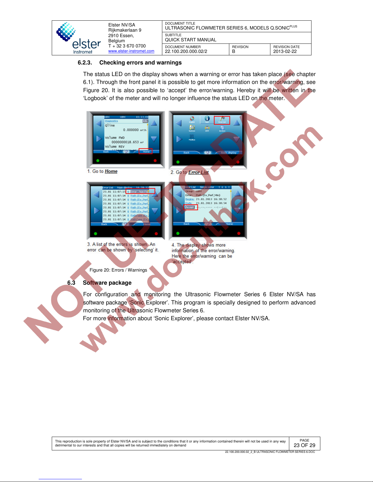
6.2.3. Checking errors and warnings
The status LED on the display shows when a warning or error has taken place (see chapter
6.1). Through the front panel it is possible to get more information on the error/warning, see
Figure 20. It is also possible to ‘accept’ the error/warning. Hereby it will be written in the
‘Logbook’ of the meter and will no longer influence the status LED on the meter.
Figure 20: Errors / Warnings
6.3 Software package
For configuration and monitoring the Ultrasonic Flowmeter Series 6 Elster NV/SA has
software package ‘Sonic Explorer’. This program is specially designed to perform advanced
monitoring of the Ultrasonic Flowmeter Series 6.
For more information about ‘Sonic Explorer’, please contact Elster NV/SA.
Page 24
Elster NV/SA
Rijkmakerlaan 9
2910 Essen,
Belgium
T + 32 3 670 0700
www.elster-instromet.com
DOCUMENT TITLE
ULTRASONIC FLOWMETER SERIES 6, MODELS Q.SONIC
PLUS
SUBTITLE
QUICK START MANUAL
DOCUMENT NUMBER
22.100.200.000.02/2
REVISION
B
REVISION DATE
2013-02-22
This reproduction is sole property of Elster NV/SA and is subject to the conditions that it or any information contained therein will not be used in any way
detrimental to our interests and that all copies will be returned immediately on demand
PAGE
24 OF 29
22.100.200.000.02_2_B ULTRASONIC FLOWMETER SERIES 6.DOC
7 Maintenance, service and repair
7.1 Introduction
The Ultrasonic Flowmeter Series 6 ultrasonic gas flow meter contains no moving parts. The
transducers and internal pressure sensor are the only components that are in contact with
the gas medium. The materials used for the transducers are selected for the measuring
conditions that were clearly specified for the instrument. As a result the transducers and the
electronics are virtually maintenance free. However, Elster NV/SA recommends inspection
of the Ultrasonic Flowmeter Series 6 with the software packages ‘SonicExplorer’ at regular
intervals (e.g. monthly). In case of degradation of the meter, appropriate measures can be
taken on time.
For detailed information about maintenance, please refer to operation and maintenance
manual (doc. code: 22.100.200.002.02/2 last valid revision).
7.2 Exchanging components
Different parts of the Ultrasonic Flowmeter Series 6 metering system like transducers,
electronic boards, etc can be exchanged easily. The digital programmed pulse shape and
pulse identification of the meter is always identical. Therefore the electronic- and transducer
products need no adjustment. This means that re-programming or re-calibration of the
meter after exchanging any identical part of the Ultrasonic Flowmeter Series 6 metering
system is not necessary.
Spare parts of the Ultrasonic Flowmeter Series 6 metering system must be supplied by
Elster NV/SA. After exchanging parts of the Q.Sonic Series 6 metering system the present
“calibration” sealing must be renewed, see the chapter 4.7.
Caution!
Before exchanging any components verify with your local
metrology authority on proper procedures. It may be required that
the operation needs to be witnessed by a representative of the
local authority.
Warning!
Exchanging of components should only be done with the same
type and model; unless otherwise specified by Elster NV/SA.
7.2.1. Pressure sensors exchange
The meter might be equipped with an optional pressure sensor for internal use (see
chapters 4.4). As the pressure sensors are specially designed for the Ultrasonic Flowmeter
Series 6, they may only be exchanged with sensors from Elster NV/SA.
Page 25
Elster NV/SA
Rijkmakerlaan 9
2910 Essen,
Belgium
T + 32 3 670 0700
www.elster-instromet.com
DOCUMENT TITLE
ULTRASONIC FLOWMETER SERIES 6, MODELS Q.SONIC
PLUS
SUBTITLE
QUICK START MANUAL
DOCUMENT NUMBER
22.100.200.000.02/2
REVISION
B
REVISION DATE
2013-02-22
This reproduction is sole property of Elster NV/SA and is subject to the conditions that it or any information contained therein will not be used in any way
detrimental to our interests and that all copies will be returned immediately on demand
PAGE
25 OF 29
22.100.200.000.02_2_B ULTRASONIC FLOWMETER SERIES 6.DOC
Warning!
For the pressure sensor it’s absolutely necessary to depressurize
the line before exchanging.
7.2.2. Temperature sensors exchange
The meter might be equipped with an optional temperature sensor for internal use (see
chapters 4.5). As the temperature sensors are specially designed for the Ultrasonic
Flowmeter Series 6, they may only be exchanged with sensors from Elster NV/SA.
As the temperature sensor only measures the flow cell temperature and is not in contact
with the gas in the pipe, exchanging can be done under pressure.
7.2.3. Transducer exchange
Each transducer is a separate component of the Ultrasonic Flowmeter Series 6 that can be
exchanged independently. This can be done without degradation of the measuring
properties and accuracy (thus the calibration) of the Ultrasonic Gas Flow Meter.
However, as the transducers are paired up during production, Elster NV/SA always
recommends changing both transducers of an acoustic path, if possible.
Warning!
Obey the rules and regulations that apply to hazardous area
operations and those with respect to custody transfer regulations
(sealing).
Exchanging a transducer can take place when the line with the Ultrasonic
Flowmeter Series 6 is depressurized:
Refer to specific installation instructions delivered with the
transducers: Transducer exchange at atmospheric conditions
(Document code: 03.200.001.001.02/2 last valid revision).
Optionally exchanging a transducer can be done when the Ultrasonic
Flowmeter Series 6 is pressurized:
A special tool is required for this: the ‘retraction tool NG transducers’.
Please familiarise yourself with the documentation regarding this
special tool: Retraction tool NG transducers (document code:
03.203.101.001.02/2 last valid revision).
Before beginning this procedure please verify if this is allowed by the
safety standards set by your company and local safety regulations. If
in doubt, DO NOT remove the transducers under pressure.
7.2.4. SPU exchange
Parts of the SPU can be exchanged without problems, provided that the appropriate
hardware and software versions are used. The product numbers can be found on the PCB
and have following structure xxx-xxx-xxx-xxx. The software version and its checksums can
be checked through the front panel (see chapter 6.1).
Page 26
Elster NV/SA
Rijkmakerlaan 9
2910 Essen,
Belgium
T + 32 3 670 0700
www.elster-instromet.com
DOCUMENT TITLE
ULTRASONIC FLOWMETER SERIES 6, MODELS Q.SONIC
PLUS
SUBTITLE
QUICK START MANUAL
DOCUMENT NUMBER
22.100.200.000.02/2
REVISION
B
REVISION DATE
2013-02-22
This reproduction is sole property of Elster NV/SA and is subject to the conditions that it or any information contained therein will not be used in any way
detrimental to our interests and that all copies will be returned immediately on demand
PAGE
26 OF 29
22.100.200.000.02_2_B ULTRASONIC FLOWMETER SERIES 6.DOC
This will not affect the measuring characteristics and the accuracy (and as a consequence
the calibration) of the Ultrasonic Flowmeter Series 6. However if the board is sealed after
calibration, please contact Elster NV/SA or your local representative before proceeding with
the exchange.
When exchanging the SPU (or parts of the SPU), refer to specific manual delivered with the
component, the Ultrasonic Flowmeter Series 6 Exchange Signal Process Unit (document
code: 03.303.201.001.02/2 last valid revision).
Page 27

Elster NV/SA
Rijkmakerlaan 9
2910 Essen,
Belgium
T + 32 3 670 0700
www.elster-instromet.com
DOCUMENT TITLE
ULTRASONIC FLOWMETER SERIES 6, MODELS Q.SONIC
PLUS
SUBTITLE
QUICK START MANUAL
DOCUMENT NUMBER
22.100.200.000.02/2
REVISION
B
REVISION DATE
2013-02-22
This reproduction is sole property of Elster NV/SA and is subject to the conditions that it or any information contained therein will not be used in any way
detrimental to our interests and that all copies will be returned immediately on demand
PAGE
27 OF 29
22.100.200.000.02_2_B ULTRASONIC FLOWMETER SERIES 6.DOC
8 Storage and shipping
As the Ultrasonic Flowmeter Series 6 is a delicate instrument, care should be taken to carefully
handle and store the flowmeter in a proper way. Improper handling, shipping or storing may void
its warranty.
The Ultrasonic Flowmeter Series 6 should be stored in indoor conditions, with a low humidity (5% -
95,% non-condensing); storage temperature should remain between -20 °C and +60 °C (long term
storage temperature: between 0 °C - +60 °C). Please refer to our ‘Ultrasonic Flowmeter Series 6
shipping and storage manual’ (document code: 22.100.200.000.35/2 last valid revision) for more
detailed information about this.
Page 28
Elster NV/SA
Rijkmakerlaan 9
2910 Essen,
Belgium
T + 32 3 670 0700
www.elster-instromet.com
DOCUMENT TITLE
ULTRASONIC FLOWMETER SERIES 6, MODELS Q.SONIC
PLUS
SUBTITLE
QUICK START MANUAL
DOCUMENT NUMBER
22.100.200.000.02/2
REVISION
B
REVISION DATE
2013-02-22
This reproduction is sole property of Elster NV/SA and is subject to the conditions that it or any information contained therein will not be used in any way
detrimental to our interests and that all copies will be returned immediately on demand
PAGE
28 OF 29
22.100.200.000.02_2_B ULTRASONIC FLOWMETER SERIES 6.DOC
9 MID requirements
9.1 General
This chapter is only applicable when the Ultrasonic Flowmeter Series 6, models Q.Sonic
plus
needs to be in accordance with European Directive 2004/22/EC on measuring instruments
(MID) as stated in EC-type Examination Certificate T10335.
The Ultrasonic Flowmeter Series 6 can be used legally for fiscal metering based on
European Directive 2004/22/EC, Annex MI-002.
9.2 EC declaration of conformity
Elster NV/SA ultrasonic gas flowmeters will be manufactured in accordance with applicable
Directives, e.g.:
• Pressure Equipment Directive (PED)
• Equipment and Protective systems intended for use in potential Explosive Atmospheres
(ATEX) Directive
• ElectroMagnetic Compatibility (EMC) Directive
• Measuring Instrument Directive (MID)
In compliance with the applicable directives the meters are supplied with the CE mark and
the EC Declaration of Conformity. This declaration is part of your flow meter documentation
since it also contains important details of your particular flow meter (e.g. PED category,
ATEX markings).
9.3 Sealing
An MID compliant meter shall be sealed (see par. 4.7).
9.4 Calibration
An MID compliant meter is accompanied by a copy of the EC Declaration of Conformity
stating compliance with Measuring Instruments Directive 2004/22/EC Annex MI-002, based
on:
• EC-Type examination certificate T10335 according MID Annex B and
• a certificate of conformity from a Notified Body according to MID Annex F.
9.5 Installation requirements
Special attention needs to be taken so that the Ultrasonic Flowmeter Series 6 and its in-
and outlet spools are mounted according to EC examination Certificate T10335 (last valid
version).
Note that parameters stated in certificate T10335 may indicate a limit or limits of a range.
The values and ranges applicable to your flowmeter may be different.
The UFM needs to be powered by an Uninterruptible Power Supply (UPS).
Please also refer chapter 5.
Page 29
Elster NV/SA
Rijkmakerlaan 9
2910 Essen,
Belgium
T + 32 3 670 0700
www.elster-instromet.com
DOCUMENT TITLE
ULTRASONIC FLOWMETER SERIES 6, MODELS Q.SONIC
PLUS
SUBTITLE
QUICK START MANUAL
DOCUMENT NUMBER
22.100.200.000.02/2
REVISION
B
REVISION DATE
2013-02-22
This reproduction is sole property of Elster NV/SA and is subject to the conditions that it or any information contained therein will not be used in any way
detrimental to our interests and that all copies will be returned immediately on demand
PAGE
29 OF 29
22.100.200.000.02_2_B ULTRASONIC FLOWMETER SERIES 6.DOC
Appendix I. References
All references below can be obtained at Elster NV/SA.
[1] MID certificate T10335 (last valid version)
Doc.-No.:T10335_certificate
[2] Ultrasonic Flowmeter Series 6 operation and maintenance manual
Doc.-No.: 22.100.200.002.02/2 last valid revision
[3] Ultrasonic Flowmeter Series 6 wiring instructions
Doc.-No.: 03.302.101.003.07/2 last valid revision
[4] Transducer exchange at atmospheric conditions
Doc.-No.: 03.200.001.001/02/2 last valid revision
[5] Retraction tool NG transducers
Doc.-No.: 03.203.101.001.02/2 last valid revision
[6] Ultrasonic Flowmeter Series 6 Exchange Signal Process Unit
Doc.-No.:03.303.201.001.02/2 last valid revision
[7] Ultrasonic Flowmeter Series 6 shipping and storage manual
Doc.-No.: 22.100.200.000.35/2 last valid revision
[8] Ultrasonic Flowmeter Series 6 Safety instructions
Doc.-No.: 22.100.200.001.02/2 last valid revision
 Loading...