

Elster Kromschroder VMF 115, Kromschroder VMF 110, Kromschroder VMF 225, Kromschroder VMF 120, Kromschroder VMF 125 Technical Information
...Page 1

Filter module VMF
Technical Information · GB
3.1.0.20 Edition 02.11
• Safe gas cleaning using filter pad and strainer
• Easy installation into a system in conjunction with valVario valves and
regulators
• Installation in any position, even with optional pressure switch
www.kromschroeder.com
Page 2

Contents
Filter module VMF . . . . . . . . . . . . . . . . . . . . . . . . . . . . . . . . 1
Contents. . . . . . . . . . . . . . . . . . . . . . . . . . . . . . . . . . . . . . . . 2
1 Application . . . . . . . . . . . . . . . . . . . . . . . . . . . . . . . . . . . . . 3
1.1 Examples of application. . . . . . . . . . . . . . . . . . . . . . . . . . 4
1.1.1 valVario double block valve with pressure regulator VCD
and VMF fitted to a forced draught burner . . . . . . . . . . . . . . . . . 4
1.1.2 valVario double block valve with variable air/gas ratio
control VCV and VMF fitted to a forced draught burner . . . . . . . 4
1.1.3 Industrial burner with staged control. . . . . . . . . . . . . . . . . . 4
1.1.4 Industrial burner with continuous control . . . . . . . . . . . . . . .5
2 Function. . . . . . . . . . . . . . . . . . . . . . . . . . . . . . . . . . . . . . . 6
3 Flow rate . . . . . . . . . . . . . . . . . . . . . . . . . . . . . . . . . . . . . . 7
3.1 Calculating the nominal size . . . . . . . . . . . . . . . . . . . . . 7
4 Selection . . . . . . . . . . . . . . . . . . . . . . . . . . . . . . . . . . . . . . 8
4.1 Type code . . . . . . . . . . . . . . . . . . . . . . . . . . . . . . . . . . . . . 8
5 Project planning information . . . . . . . . . . . . . . . . . . . . . . 9
5.1 Installation . . . . . . . . . . . . . . . . . . . . . . . . . . . . . . . . . . . . 9
6 Accessories . . . . . . . . . . . . . . . . . . . . . . . . . . . . . . . . . . . 10
6.1 Seal set VA 1 – 3 . . . . . . . . . . . . . . . . . . . . . . . . . . . . . . . 10
6.2 Filter pad set . . . . . . . . . . . . . . . . . . . . . . . . . . . . . . . . . 10
7 Technical data . . . . . . . . . . . . . . . . . . . . . . . . . . . . . . . . . . 11
7.1 Dimensions . . . . . . . . . . . . . . . . . . . . . . . . . . . . . . . . . . . 12
7.1.1 VMF..R. . . . . . . . . . . . . . . . . . . . . . . . . . . . . . . . . . . . . . . . . . . 12
7.1.2 VMF..N . . . . . . . . . . . . . . . . . . . . . . . . . . . . . . . . . . . . . . . . . .13
7.1.3 VMF 240F . . . . . . . . . . . . . . . . . . . . . . . . . . . . . . . . . . . . . . . .14
8 Maintenance. . . . . . . . . . . . . . . . . . . . . . . . . . . . . . . . . . 15
Feedback . . . . . . . . . . . . . . . . . . . . . . . . . . . . . . . . . . . . . . 16
Contact . . . . . . . . . . . . . . . . . . . . . . . . . . . . . . . . . . . . . . . . 16
2
VMF · Edition 02.11
t
= To be continued
Page 3

Application
1 Application
VMF2..1-4 VMF2..R..M
The filter module VMF is designed for cleaning the gas and air
flow to gas burners or gas appliances. It is suitable for use in
gas control and safety systems in all sectors of the iron, steel,
glass and ceramics industries, and also in all areas of private
and commercial heat generation.
It can easily be adapted to different pipes thanks to various
flange shapes for the individual valVario valve sizes. Its modular design allows assembly with valVario valves or regulators
making it possible to construct space-saving gas systems.
3
Forced draught gas burner with valVario controls
VMF · Edition 02.11
Roller hearth furnace
Page 4
Application
4
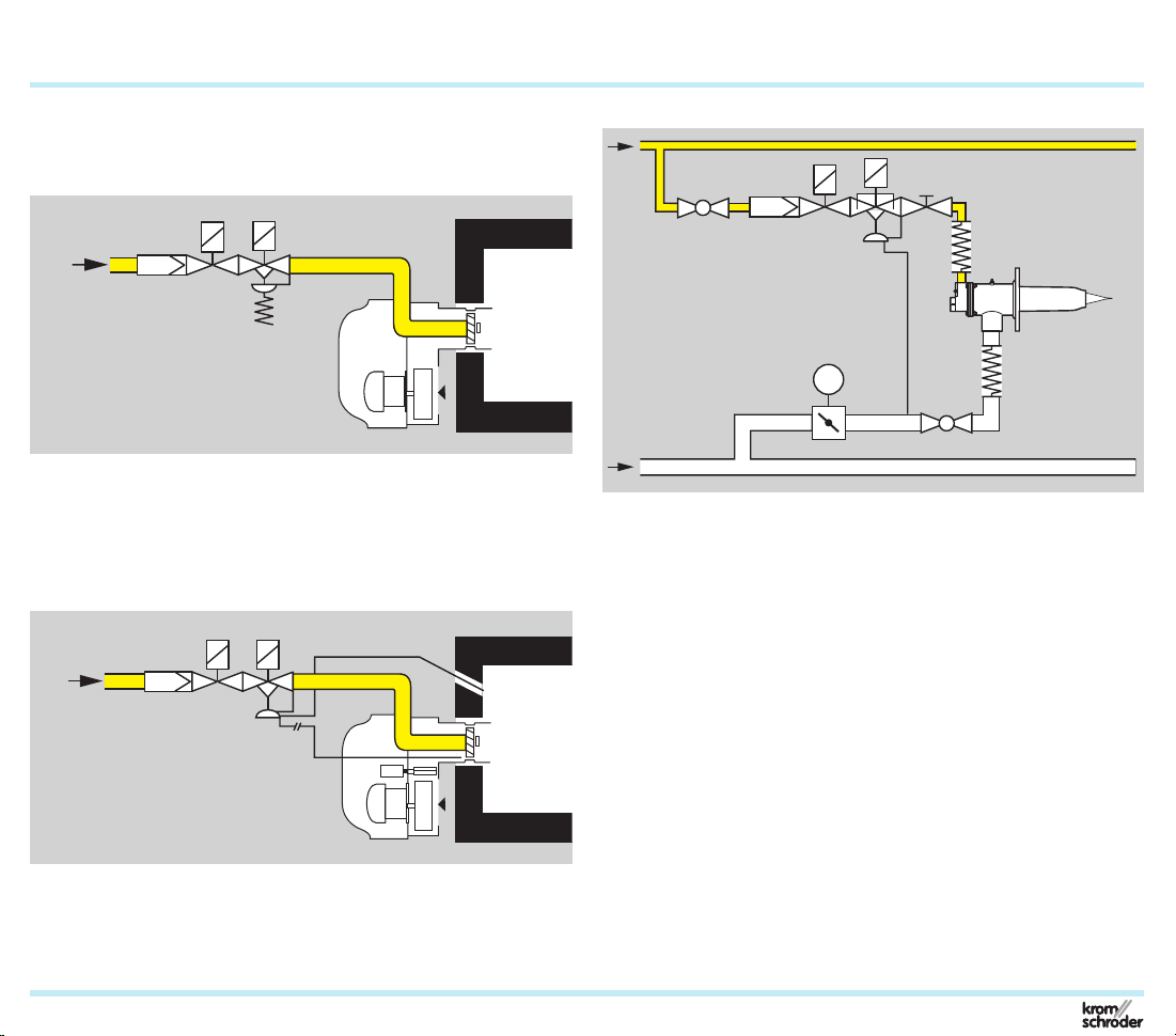
1.1 Examples of application
1.1.1
valVario double block valve with pressure regulator VCD
and VMF fitted to a forced draught burner
VCD
VMF
This type of control is used on one-stage forced draught burn-
ers or in one-stage boilers, it is also suitable for use with a
mechanical or electronic air/gas ratio control system.
1.1.2 valVario double block valve with variable air/gas ratio
control VCV and VMF fitted to a forced draught burner
VCV
VMF
p
F
1.1.3 Industrial burner with staged control
VAG
VMV
EKO
BIC
EKO
LEH
AKT
VMF
VAS
+VBY
IC 40 + BVA
M
The high output impulse at the burner generated by this type
of control produces a uniform temperature distribution and
good circulation of the furnace or kiln atmosphere, e.g. in heat
treatment furnaces in the iron and non-ferrous metal industries
or kilns for heavy clay and fine ceramics. The required lambda
value can be set using the fine-adjusting valve VMV and the
air adjusting cock LEH. Using the filter module VMF, the gas
flow upstream of the gas valve VAS is cleaned.
p
L
With this type of continuous control, the mixture setting is
maintained over a wide control range while at the same time
preventing air deficiency.
VMF · Edition 02.11
Page 5

Application > Examples of application
1.1.4 Industrial burner with continuous control
5
Three-
point
step
VMF
IC 20 + BVA
VAS
M
VAG
VMV
BVA
EKO
ZIO, BIO, BIOA
EKO
LEH
Using the filter module VMF, the gas flow upstream of the
gas valve VAS and the air/gas ratio control VAG is cleaned.
The gas/air mixture is set using the fine-adjusting valve VMV.
A constant mixture setting is maintained over a wide control
range while at the same time preventing air deficiency. This
type of control is used on boilers with multi-stage or infinitely
adjustable forced draught burners.
VMF · Edition 02.11
Page 6

2 Function
6
Pressure switch DG..VC
Pressure test point
Flange
Retaining frame
with strainer
Filter pad
Housing
Base plate
VMF..M with test points
There is a retaining frame with an integrated strainer and filter
pad in the housing of the VMF. The filter pad is supported by
the strainer. The filter pad and the strainer rid the gas of coarse
as well as fine impurities.
In order to replace the filter pad, the two retaining screws are
undone and the base plate removed. The retaining frame with
the filter pad is pulled out. The retaining frame is opened and
the filter pad can be taken out.
The VMF is delivered with two test points for pressure measure-
ment as standard. The VMF can also optionally be delivered
with two 1/8“ screw plugs.
COM
Pressure test point
NC
NO
Flange
Retaining frame
with strainer
Filter pad
Housing
Base plate
VMF..1 to 4 with pressure switch DG..VC
The VMF..1 to 4 is equipped with a pressure switch for moni-
toring minimum or maximum pressure. The pressure switch
monitors the outlet pressure downstream of the filter pad. In
addition, there is also a test point for measuring the pressure
directly.
VMF · Edition 02.11
Page 7

7
●
Natural gas
0.80
kg/m3
20.9
m3/h
400
10.0
mbar
mbar0°C
15.0
m3/h
[mbar]
[m/s]
VMF 110 | 9.2| 29
VMF 115 | 4.5| 18
VMF 120 | 1.3| 11
VMF 125 | 0.8| 7
VMF 225 | 0.4| 7
VMF 232 | 0.2| 4
VMF 240 | 0.1| 3
3 Flow rate
8
6
5
4
∆p [inch WC]
3
2
0,8
0,6
0,5
0,4
0,3
0,2
0,8
0,6
0,5
0,4
= natural gas (ρ = 0.80 kg/m3)
= propane (ρ = 2.01 kg/m3)
= air (ρ = 1.29 kg/m3)
The characteristic curves are measured at
15°C (59°F) with a measurement set-up in accordance with the standards EN 13611/EN 161.
VMF · Edition 02.11
20
∆p [mbar]
10
8
6
5
4
1
1
3
2
1
0,8
0,6
0,5
0,4
0,3
0,2
0,1
1
2
3
0,8 1 2 3 4 6 8 10 20 30 40
1
30 40 60 100 200 10000400 2000 300 0 5000600 1000
21 3 4 6 8 10 20 30 40
1 2 3 4 6 8 10 20 30
0,7
VMF 110
VMF 115
VMF 125
VMF 120
60 100
40 60
VMF 225
60 100
VMF 232
VMF 240
VMF 250
200 300 500
100 200 300
200 300
V' n [m3/h]
V' [SCFH]
This involves measuring the pressure 5 x DN
upstream and downstream of the unit under
test. The pressure drop of the pipe is also
measured but is not compensated for.
A pressure loss of 10 mbar must not be ex-
ceeded.
Reading instructions:
Should operating cubic metres (V
·
b) have
been used in the flow rate diagram, instead
of standard cubic metres (
V·
n), then the pres-
sure loss read must be multiplied by the
absolute inlet pressure in bar (1+positive
pressure in bar).
Example:
inlet pressure p
(positive pressure) = 0.4bar,
e
gas type: natural gas,
operating flow rate
V·
b = 15 m
3
/h,
selected filter module: VMF 120
∆p from diagram = 3.1 mbar,
∆p = 3.1 mbar x (1 + 0.4) = 4.5 mbar.
The VMF 120 has been selected correctly.
3.1 Calculating the nominal size
Standard T-product
Flow rate
Inlet pressure p
Medium temperature
Flow rate
Product
·
(V
n)
e
∆p
max.
·
(V
b)
∆p v
Page 8

4 Selection
* Specifi cation omitted, if the nominal diameter of the inlet and outlet fl anges is the same.
1)
* Specifi cation omitted, if the nominal diameter of the inlet and outlet
Type – 10 15 20 25 32 40 50 /–* /10* /15*
VMF 1
VMF 2
= standard, = available
Only available for VMF 240.
4.1 Type code
Code Description
VMF Filter module
1–2 Size
–
10–50
/–
/10–/50
R
N
F
05 p
M
P
1
With outlet pressure switch: DG 17/VC
2
3
4
Without inlet fl ange
Nominal inlet diameter
Without outlet fl ange*
Nominal outlet diameter
NPT internal thread
Flange to ISO 7005
With pressure test points
/20*/25*/32*/40*/50*
Rp internal thread
500 mbar
e max
With screw plugs
DG 40/VC
DG 110/VC
DG 400/VC
8
R N F 1) 05 M P 1 2 3 4
fl anges is the same.
VMF · Edition 02.11
Page 9

5 Project planning information
5.1 Installation
Installation position: VMF can be installed as required.
We recommend installation with the base plate pointing
downwards or sideways so that dirt can be removed from
the housing more easily.
Installation position when using valVario valves and regulators:
the VMF is fitted upstream of the valVario control.
The VMF can be installed as a standalone device in the pipe.
9
VMF · Edition 02.11
Page 10

10
6 Accessories
6.1 Seal set VA 1 – 3
A B
Scope of delivery:
A 1 x double block seal,
B 2 x O-rings (flange),
C 2 x O-rings (pressure switch),
D 2 x sealing rings (test point).
C
D
6.2 Filter pad set
A
Scope of delivery:
A 1 x retaining frame with strainer,
B 10 x filter pads,
C 10 x seals for the base plate,
D 2 x seals for 1/8” test points,
E 2 x screws for securing the base plate.
B
D
C
E
VMF · Edition 02.11
Page 11

7 Technical data
Gas types:
natural gas, LPG (gaseous), biologically produced methane
(max. 0.1 %-by-vol. H2S) or air; other gas types on request.
The gas must be dry in all conditions and must not contain
condensate.
Max. inlet pressure p
max. 500 mbar (7.25 psig).
Ambient temperature:
-20 to +60°C (-4 to +140°F),
no condensation permitted.
Storage temperature:
-20 to +40°C (-4 to 104°F).
Housing: aluminium.
Connection flanges:
with internal thread: Rp to ISO 7-1, NPT to ANSI/ASME,
with ISO flange: DN 40 to ISO 7005.
:
e
11
VMF · Edition 02.11
Page 12

* Without fl anges.
Technical data
7.1 Dimensions
12
H1
H2
VMF..R..M, VMR..R..P
D
L1
F
VMF..R..1-4
H3
H2
D
L1
F
7.1.1 VMF..R
Dimensions Weight
Type
Connection
L1 F D H1 H2 H3
Rp DN mm mm mm mm mm mm kg kg kg
VMF 110 3/8 10 30 15 62.7 65.1 44.6 99 0.34 0.49 0.07
VMF 115 1/2 15 30 15 62.7 65.1 44.6 99 0.34 0.49 0.06
VMF 120 3/4 20 30 23 62.7 65.1 44.6 99 0.34 0.49 0.11
VMF 125 1 25 30 23 62.7 65.1 44.6 99 0.34 0.49 0.09
VMF 225 1 25 34 29 88 81 65.2 114.6 0.76 0.91 0.29
VMF 232 11/4 32 34 29 88 81 65.2 114.6 0.76 0.91 0.26
VMF 240 11/2 40 34 29 88 81 65.2 114.6 0.76 0.91 0.29
VMF 250 2 50 34 29 88 81 65.2 114.6 0.76 0.91 0.22
VMF..R..P*,
VMF..R..M*
VMF..N..1-4* Flange
VMF · Edition 02.11
Page 13

* Without fl anges.
Technical data > Dimensions
H3
H1
H2
D
L1
F
VMF..N..M, VMR..R..P
VMF..N..1-4
7.1.2 VMF..N
Dimensions Weight
Type
VMF 110 3/8 10 1.18 0.59 2.46 2.56 1.76 3.89 0.75 1.08 0.15
VMF 115 1/2 15 1.18 0.59 2.46 2.56 1.76 3.89 0.75 1.08 0.14
VMF 120 3/4 20 1.18 0.91 2.46 2.56 1.76 3.89 0.75 1.08 0.23
VMF 125 1 25 1.18 0.91 2.46 2.56 1.76 3.89 0.75 1.08 0.20
VMF 225 1 25 1.34 1.14 3.46 3.19 2.57 4.51 1.66 2.01 0.64
VMF 232 11/4 32 1.34 1.14 3.46 3.19 2.57 4.51 1.66 2.01 0.57
VMF 240 11/2 40 1.34 1.14 3.46 3.19 2.57 4.51 1.66 2.01 0.65
VMF 250 2 50 1.34 1.14 3.46 3.19 2.57 4.51 1.66 2.01 0.49
Connection
L1 F D H1 H2 H3
NPT DN inch inch inch inch inch inch lbs lbs lbs
H2
D
F
VMF..N..P*.
VMF..N..M*
L1
VMF..N..1-4* Flange
13
VMF · Edition 02.11
Page 14

Technical data > Dimensions
* Without fl anges and connection parts.
H1
14
D
H3
H2
L1
F
VMF 240/40F..M, VMF 240/40F..P
H2
L1
F
VMF 240/40F..1-4
7.1.3 VMF 240F
Dimensions Weight
Type
Connection
L1 F D H1 H2 H3
DN mm mm mm mm mm mm kg kg kg
VMF 240 40 34 66 88 81 65.2 114.6 0.76 0.91 1.04
VMF · Edition 02.11
VMF..F..P*,
VMF..F..M*
VMF..F..1-4* Flange
Page 15

8 Maintenance
Check for external tightness at least once per annum, at least
twice per annum for operation with biologically produced
methane. Replace filter pad as required, see page 10 (Filter
pad set).
15
VMF · Edition 02.11
Page 16

16
Kromschröder AG
Michael Rehkamp
m.rehkamp@kromschroeder.com
Osnabrüc
k
Feedback
Feedback
Finally, we are offering you the opportunity to assess this “Technical Information (TI)” and to give us your opinion, so that we
can improve our documents further and suit them to your needs.
Clarity
Found information quickly
Searched for a long time
Didn’t find information
What is missing?
No answer
Use
To get to know the product
To choose a product
Planning
To look for information
Remarks
Contact
Contact
Elster GmbH
Postfach 2809 · 49018 Osnabrück
Strotheweg 1 · 49504 Lotte (Büren)
Germany
T +49 541 1214-0
F +49 541 1214-370
info@kromschroeder.com
www.kromschroeder.com
www.elster.com
VMF · Edition 02.11
Comprehension
Coherent
Too complicated
No answer
Navigation
I can find my way around
I got “lost”
No answer
The current addresses of our international
agents are available on the Internet:
www.kromschroeder.com Sales
Scope
Too little
Sufficient
Too wide
No answer
My scope of functions
Technical department
Sales
No answer
(Adobe Reader 7 or higher required)
We reserve the right to make technical
modifications in the interests of progress.
Copyright © 2007 – 2011 Elster Group
All rights reserved.
03250962
 Loading...