

Page 1
J48 2½”- 6”
Commissioning Instructions
OPERATING INSTRUCTIONS
• Ensure that this product is suitable for the chosen application.
• Installation, adjustment and maintenance by authorised, trained personnel only.
• When being fitted to an appliance, refer to the appliance manufacturers
instructions.
Warning! Incorrect installation, adjustment, modification, operation and maintenance may
cause injury or damage.
Read the instructions before use. This control must be installed in accordance with the rules in
force.
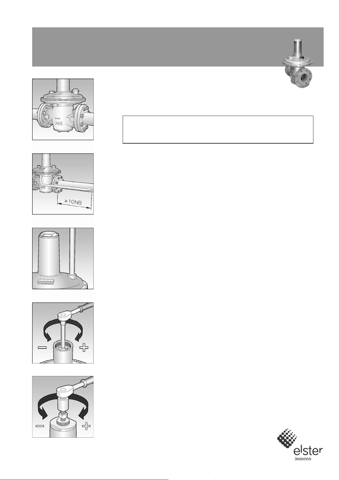
Fig. 1
Fig. 2
Fig. 3
Fig. 4
FITTING UNITS INTO PIPEWORK
1. Remove the protection from the inlet and outlet ports.
2. Ensure that the installation pipework is thoroughly clean.
3. The direction of gas flow must be the same as the arrows on the regulator body.
See Fig. 1.
4. Install regulator into pipework.
INSTALLATION OF EXTERNAL IMPULSE LINE (IF REQUIRED)
1. Remove the plastic protection plug.
2. Connect the impulse line (½"), using a jointing compound approved to national
standards, and lead to a point downstream not less than ten times the nominal
pipe diameter from the outlet. See Fig. 2.
INSTALLATION OF VENT LINE (IF REQUIRED)
1. Remove breather cover from regulator top case / cover.
2. Connect the vent line (½"), using a jointing compound approved to national
standards, and lead to atmosphere in accordance with national standards.
Ensure that no water can penetrate vent pipe. See Fig. 3.
3. If vent connection is to be used for top loading or other similar use refer to your
own installation instructions.
SETTING OF OUTLET PRESSURE
1. Turn off inlet and outlet valves.
2. Remove top cap.
3. For L.P. 65mm and 80mm unit insert ½" square socket extension piece into
square hole, or flat blade screwdriver into slot in spring adjuster. See Fig. 4.
4. For H.P. 65mm and 80mm unit and L.P. 100mm and 150mm unit, slacken
locknut on spring adjusting stem and connect suitable spanner (24mm A/F) to
hexagon of spring adjusting stem. See Fig. 5.
5. For 100mm and 150mm H.P. unit connect suitable spanner (27mm A/F) to
hexagon of spring adjusting nut. See Fig. 6.
6. Turn spring adjustment anticlockwise to reduce pressure on loading spring.
7. Slowly turn on inlet supply.
8. Increase loading on spring by turning spring adjustment clockwise until the
required outlet pressure, plus approximately 2.5mbar, is obtained).
9. Commission downstream appliance(s).
10. Trim the outlet pressure of the regulator, if necessary, when normal working flow
rates have been achieved.
11. Replace the top cap.
Fig. 5
Page 2
J48: 2½” – 6” Commissioning Instructions
IF THE REQUIRED OUTLET PRESSURE CAN NOT BE ACHIEVED WITH
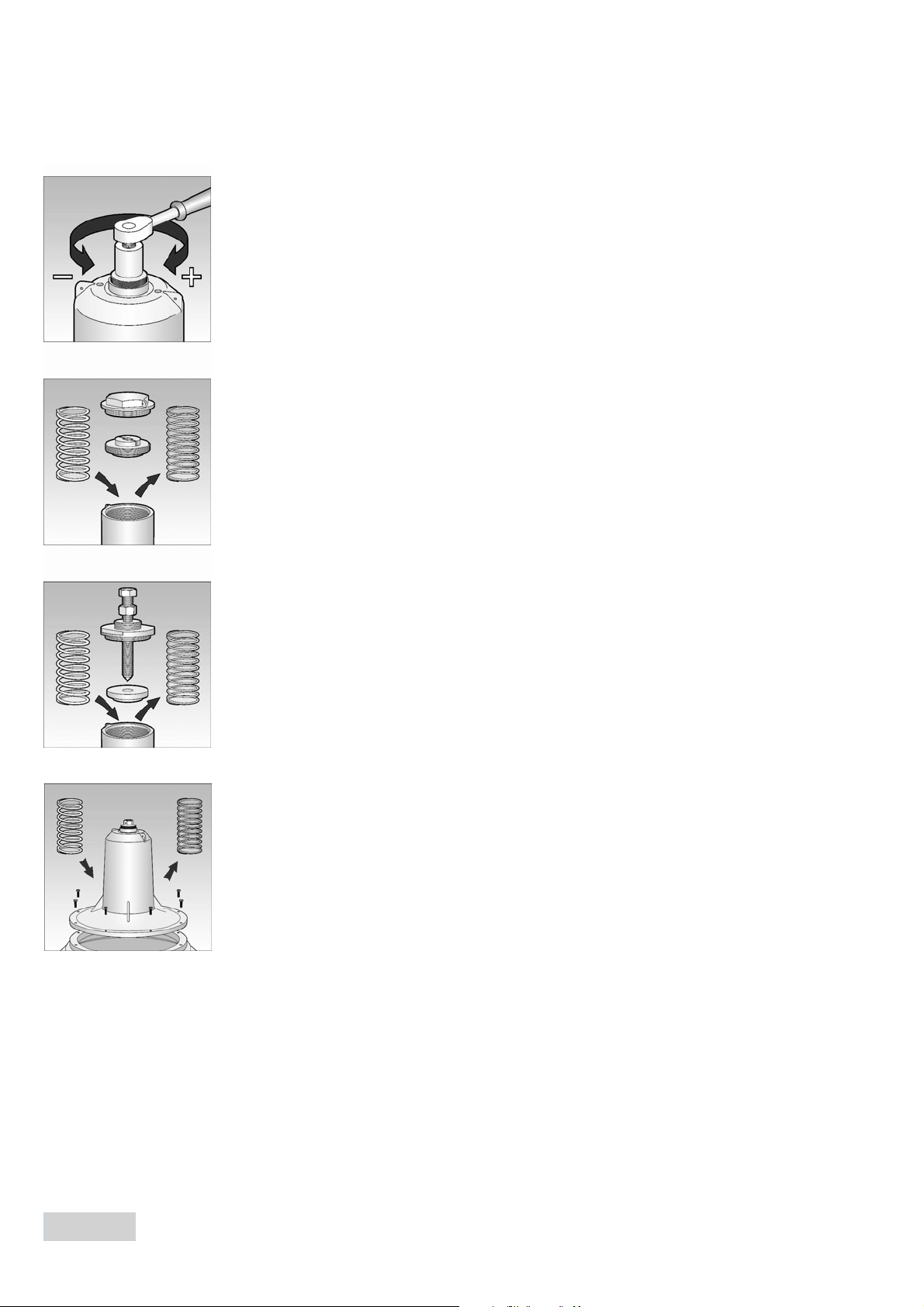
THE SPRING FITTED.
1. Choose a loading spring from the catalogue that will give the required outlet
pressure range.
For L.P. 65mm and 80mm units: See Fig. 7.
2. Remove top cap.
3. Fully unscrew and remove the spring holder.
4. Remove loading spring.
Fig. 6
5. Insert new loading spring.
6. Screw spring holder back in place ensuring that spigot is located in loading
spring.
7. Adjust the outlet pressure, as described earlier, until the required setting is
achieved.
8. Replace top cap.
For H.P. 50mm and 80mm & L.P. 100mm and 150mm units: See Fig. 8.
9. Remove top cap.
10. Slacken locknut on spring adjusting stem.
Fig. 7
11. Turn spring adjuster anticlockwise to reduce loading on spring.
12. Unscrew spring adjusting bush.
13. Remove top spring holder and loading spring.
14. Insert new loading spring.
15. Place top spring holder over spring ensuring that spigot is located in loading
spring.
16. Screw spring adjusting bush into top cover making sure that the end of the stem
is located in the recess in the top spring holder.
17. Adjust the outlet pressure, as described earlier, until the required setting is
achieved.
Fig. 8
18. Tighten locknut.
19. Replace top cap.
For H.P. 100mm and 150mm units: See Fig. 9.
20. Remove top cap.
21. Turn spring adjusting nut anticlockwise to reduce loading on spring.
22. Remove 8 hexagon head screws that secure top cover to top diaphragm case.
Carefully lift off top cover assembly and gasket.
23. Remove loading spring.
24. Install new loading spring over spring location washer in centre of diaphragm.
Fig. 9
25. Replace gasket and top cover assembly and secure with 8 hexagon head
screws.
26. Adjust the outlet pressure, as described on earlier, until the required setting is
found.
27. Replace top cap.
Contacts
United Kingdom Germany USA
Elster Jeavons Elster GmbH Elster American Meter
Tollgate Business Park, Beaconside Steinern Str. 19 - 21 2221 Industrial Road
Stafford, Staffordshire ST16 3HS 55252 Mainz-Kastel Nebraska City, NE 68410-6889
T +44 1785 275200 T +49 6134 605 0 T +1 402 873 8200
F +44 1785 275305 F +49 6134 605 223 F +1 402 873 7616
www.jeavonsltd.co.uk www.elster-instromet.com www.elster-meterservices.com
info.jeavons@gb.elster.com info@elster-instromet.com
C483EN01
A25.1.2008
Subject to change without prior notice All rights reserved
Subject to change without prior notice All rights reserved
 Loading...