

Page 1

Gas quality analyser Q1
Technical documentation
Function, operation,
commissioning and maintenance
FCQ1-BAShort-EN a 19.3.2013
2013 Elster GmbH Edition a 19.3.2013
Page 2

Copyright
2013 Elster GmbH
GAS-WORKS, Z1, gas-lab Q1, and FLOW COMP are German
registered trademarks of Elster.
Microsoft, Windows and Windows NT are registered trademarks
of Microsoft Corporation.
HART is a registered trademark of HART Communication
Foundation.
Elster GmbH
Schlossstraße 95a
D - 44357 Dortmund, Germany
Tel.: +49 231 937110-0
Fax: +49 231 937110-99
E-mail: info@elster-instromet.com
Page ii gas-lab Q1
Page 3

Contents
Safety and warning notes ................................................................................. v
1 Introduction ............................................................................................... 1
1.1 The gas-net system idea ...................................................................... 1
1.2 The measuring principle ....................................................................... 1
2 Device view and design ............................................................................ 5
2.1 Sensor system ..................................................................................... 5
2.2 Evaluation computer ............................................................................ 7
3 Operating gas-net devices ..................................................................... 11
3.1 The keypad ........................................................................................ 11
3.2 Other operating elements: status LED, calibration switch .................. 12
3.3 Display ............................................................................................... 14
3.4 Displays / Menus / Dialogs ................................................................. 14
4 Primer for impatient operators: What do I have to do to …? ............. 25
4.1 ... view the gas quality error listing? ................................................... 25
4.2 … accept the gas quality measurement errors? ................................. 26
4.3 … check all parameter settings? ........................................................ 27
4.4 … check the input values? ................................................................. 28
4.5 … view and check the outputs? ......................................................... 28
4.6 … view the archives? ......................................................................... 28
5 Functional description ............................................................................ 29
5.1 Gas quality module ............................................................................ 29
5.2 Data logging module .......................................................................... 53
5.3 Monitoring module ............................................................................. 59
5.4 System module ................................................................ .................. 78
5.5 Integrated RDT module ...................................................................... 87
5.6 DSfG module, Data exchange module ............................................... 89
6 GAS-WORKS / GW-GNET+ ..................................................................... 97
6.1 Compiling and exporting a parameterisation: Brief description .......... 98
6.2 Importing and editing a parameterisation: Brief description ............. 101
6.3 Extras: GW-GNET+ service programs ............................................. 103
6.4 Optional: GW-Remote+ for downloading archives ........................... 105
gas-lab Q1 Page iii
Page 4

7 Installation ............................................................................................. 107
7.1 Mounting the gas-net Q1 ................................................................. 107
7.2 Connecting the lines ........................................................................ 107
7.3 Mounting the sensor system ............................................................ 117
8 Commissioning ..................................................................................... 121
8.1 Parameter protection against unauthorised access ......................... 121
8.2 Parameterisation ............................................................................. 122
8.3 Sealing of the device (if applicable/when required) ......................... 122
8.4 Commissioning of Integrated RDT module ..................................... 122
8.5 Commissioning the sensor system .................................................. 123
9 Maintenance .......................................................................................... 125
9.1 Maintaining the gas-net Q1 evaluation computer ............................ 125
9.2 Maintaining the gas-lab Q1 sensor system ...................................... 128
10 Technical data: Q1 ................................................................................ 129
10.1 Device type ...................................................................................... 129
10.2 Sensor technology details (gas-lab Q1) ........................................... 129
10.3 Evaluation computer details (gas-net Q1)........................................ 131
11 Annex ..................................................................................................... 135
11.1 Error listing of the gas-lab Q1 .......................................................... 135
11.2 Menue structure of the Q1 ............................................................... 145
12 Index ...................................................................................................... 147
Page iv gas-lab Q1
Page 5

Safety and warning notes
To ensure a safe and faultless operation of the device the instructions and
notes contained in the documentation on hand must be observed.
The device must be used as prescribed and connected according to the
connection diagram. The national and local regulations for electrical
installations must be observed.
The mounting, electrical installation, commissioning and maintenance of
the entire measuring system must be performed by qualified staff who
have been trained in the field of explosion protection and have read and
understood all parts of the operating instructions necessary for the
actions to be carried out.
Please refer to the corresponding technical regulations (DIN, DIN EN, VDE,
VDI, and DVGW) for general information on mounting, commissioning,
taking out of service and maintaining. Below, we have listed the standards
and guidelines that must be observed:
DIN EN 60079-14, Publication date: 1998-08, Electrical apparatus for
explosive gas atmospheres – Part 14: Electrical installations in hazardous
areas (other than mines)
DIN EN 50110-1, Publication date: 1997-10, Operation of electrical
installations
DIN EN 60079-17, Publication date: 1999-08, Electrical apparatus for
explosive gas atmospheres – Part 17: Inspection and maintenance of
electrical installations in hazardous areas (other than mines)
DIN VDE 0100-610, Publication date: 1994-04, Erection of power
installations with nominal voltages up to 1000 V; initial verification
gas-lab Q1 Page v
Page 6

gas-lab Q1 sensor system (sensor technology):
The sensor system must neither be stored at temperatures below
-20°C nor above +55°C.
Connect the electrical cables only to the EEx-e approved junction box!
This junction box is located on the mounting plate of the gas-lab Q1.
The sensor system is supplied by 24 V DC and must be secured
externally by 2.5 A.
Include the housing and mounting plate in the local earthing system.
A temperature between +5 deg. C and +40 deg. C must be guaranteed
during the operation of the sensor system (-x to +40 deg. C with
additional heater, -x to +55 deg. C with cooling unit; the lower
temperature limit depends on the heat output).
Only gases of the second gas family according to DIN DVGW 460 or
approved calibration gases are permissible. The oxygen content in the
natural gas must not be higher than 2.0 percent by volume.
The ventilation must be connected to the exhaust gas manifold via a
stainless steel tube with a minimum inside diameter of 4 mm.
After a voltage failure the measuring system automatically purges
with process gas before it activates the sensors. After a new gas
cylinder with flammable contents has been connected, the system
must be purged manually before the normal measurement can be
continued. This also applies if air may have got into a gas pipeline
connected to the sensor system (see also Chapter 5.1.4).
The user must ensure by means of high-pressure reduction and safety
devices that all gases injected into the measuring system do not
exceed an inlet pressure of 1,250 mbars absolute!
The opening of the housing as well as inspection and maintenance
must be carried out by specialists authorised by Elster!
Page vi gas-lab Q1
Page 7

Only if the atmosphere is not explosive or in de-energised conditions
after a delay of 5 minutes after the electrical supply has been
disconnected, the cover of the housing may be opened!
The cable entries for the electrical connections of the EEx d housing
of the measuring system must never be loosened if the atmosphere is
explosive!
The loosening or unscrewing of the breather is prohibited!
Only authorised personnel is allowed to exchange the breather, if
need be. In this case, the breather as a whole must be exchanged!
Only authorised personnel are allowed to exchange a cable entry
gland, if necessary.
The sensor system may only be switched on before or together with
the gas-net Q1 evaluation computer. It will result in an error (alarm) if
you switch on the sensor system after having switched on the
evaluation computer.
gas-lab Q1 Page vii
Page 8

gas-net Q1 evaluation computer:
The gas-net Q1 evaluation computer must neither be stored at
temperatures below -20°C nor above +55°C.
A temperature between 0 deg. C and +40 deg. C must be guaranteed
during operation.
The gas-net Q1 must be installed outside ex-zone 2.
The gas-net Q1 evaluation computer may contain subassemblies that
are approved as associated electrical apparatus of the ib category
according to DIN EN 50020 with intrinsically safe circuits. This renders
the electronic evaluation computer Q1 suitable for connection to
sensors and pulse generators located in hazardous areas (e.g.
zone 1).
A mixed connection of intrinsically safe and not intrinsically safe
circuits is not permitted in case of these subassemblies.
The evaluation computer is supplied by 24 V DC and must be secured
externally by 1 A.
The earthing is connected to PE of the power supply connector for
equipotential bonding.
Observe the regulations of the relevant standards, in particular of DIN
EN 50014, DIN EN 50020, and DIN EN 50029.
Observe the limit values stated in the respective certificates of
conformity of the boards to be connected.
Warning: The evaluation computer of the Q1 measuring system is a class
A device that may cause interferences in living areas; in this case, the
user may be asked for appropriate measures at his expense.
Page viii gas-lab Q1
Page 9

Introduction 1
1 Introduction
1.1 The gas-net system idea
is the generic term for an Elster device family. The evaluation
computer of the gas-lab Q1, too, is based on the gas-net device
family. All gas-net devices, including future device types, are characterised by
uniformity in appearance, operation and parameterisation.
Each Elster device always covers a multitude of measurement and control
functionalities.
gas-net devices also provide this functional variety. To keep the operation and
parameterisation of the devices well structured and user-friendly, the gas-net
series is based on a modular concept. A module corresponds to a special
functionality. Each module has its own main display within the device’s menu
assistance, and each module has its own group of settings within the parameter
data record.
A particular module can be employed in different device types. This yields a
modular system that is advantageous to the user as a particular module can
always be operated and adjusted in the same way, no matter in which device
type it has been installed.
1.2 The measuring principle
The gas-lab Q1 measuring system is a gas quality analyser that performs
infrared absorption and thermal conductivity measurements. The primary target
variables are the gross calorific value, standard density and CO2 content of the
natural gas being measured.
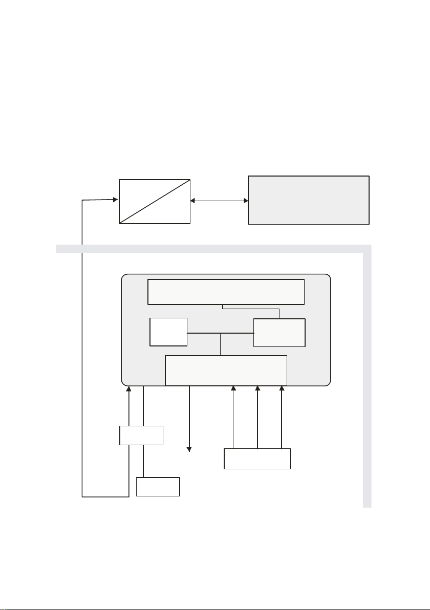
The entire measuring system consists of two components:
1. gas-lab Q1 sensor system
The actual sensor technology is located in an explosion-proof housing,
which can be installed in a hazardous environment.
2. gas-net Q1 evaluation computer
The evaluation computer of the Q1 measuring system is located in a nonhazardous environment. The main tasks of the evaluation computer are
controlling and monitoring the measuring process, evaluating the sensor
measurements, calculating the target variables and supporting the user
during calibration. Furthermore, the evaluation computer contains an
gas-lab Q1 Page 1
Page 10
1 Introduction
gas-lab Q1 sensor system
Vent gas line
RS422,
4-wire
Hazardous
area
Non-hazardous
area
Gas supply
24 VDC
Sensor unit
Sensor
elektronics
Double-block&bleed
valve set
RS422 / optical fibre
converter
gas-net
Q1
evaluation computer
optical fibre
EEX-e
Communi-
cations
PTB
integrated data logging function, mainly for interval- and event-controlled
data logging of analysis data as well as of error listing and logbook. The
signal and message processing provides some digital and analogue output
possibilities. The evaluation computer also controls the measuring process
and calculates the target variables.
Page 2 gas-lab Q1
Page 11

Introduction 1
The connection between sensor system and evaluation computer is
implemented via interface cable, RS422/optical fibre-converter and fibre-optics
cable, as illustrated above.
The sensor system contains two infrared sensors for measuring the absorption
of the hydrocarbons and carbon dioxide contained in the natural gas. Another
sensor additionally determines the thermal conductivity of the natural gas and
thus also measures gas components such as nitrogen, for instance, which
cannot absorb infrared light. Afterwards the evaluation computer evaluates all
three measurements. As a result, these measurements supply the gross calorific
value, standard density and CO2 content of the natural gas. These variables are
sufficient to establish with a flow computer the compressibility ratio k (real gas
dependence) according to SGERG and the energy content of the natural gas.
Besides, other variables such as the Wobbe and methane numbers are also
determined. Other than that mentioned, the system provides also a noncalibratable sample analysis of the natural gas. The underlying algorithm is
based on the systematic of the composition of natural gases. In case of nontypical gases a major deviation in the measured value of a single component
can occur.
The device measures continually and determines new measurements every
second. It can therefore also be used for fast closed-loop control tasks.
The manufacturer calibrates the gas-lab Q1 before delivery, i.e. he performs a
zero point adjustment with nitrogen and afterwards a 3-point calibration with
ultra-pure methane and two calibration gases. The correction values are saved
in the sensor unit. This basic calibration is usually repeated during the
commissioning and on the occasion of a recalibration.
The evaluation computer automatically performs a 1-point calibration with ultrapure methane after a mains failure and after each switching on of the measuring
sensor technology.
Moreover, the gas-net Q1 offers a wealth of additional functions for monitoring
tasks and data communications. The gas-net Q1 also always includes a data
logging function that logs important measurements at defined intervals and
when errors occur. See Chapter 5.2 for a detailed description of the archive
structure.
gas-lab Q1 Page 3
Page 12

Page 13
View and design 2
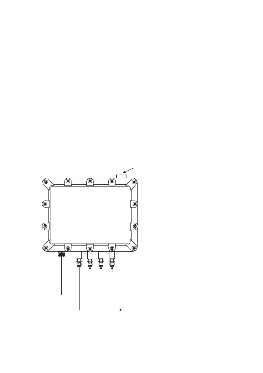
breather
EEx-d junction
(voltage supply,
data connection)
3: Calibration gas connection (i.e. N2, H2-11K, L1-8K)
2: Calibration gas connection (methane)
1: Process gas connection
Vent gas line
2 Device view and design
2.1 Sensor system
The actual sensor technology of the gas-lab Q1, the sensor system, is mounted
in an explosion-proof housing. The gas is supplied at approximately 80 mbars
overpressure and via a double block & bleed solenoid valve set, which is also
located inside the housing. There are a total of three gas inlets for different
gases, one connection for the process gas and two connections for calibration
gases. The out flowing gas is led via a vent gas line.
The housing is mounted on a mounting plate in such a way that the gas and
other process connections point downwards. In order to ensure that the housing
withstands the maximum permissible inside pressure of 1,100 mbars, a breather
is led out of the housing at the top. The following illustration shows the front of
the sensor housing:
gas-lab Q1 Page 5
Page 14
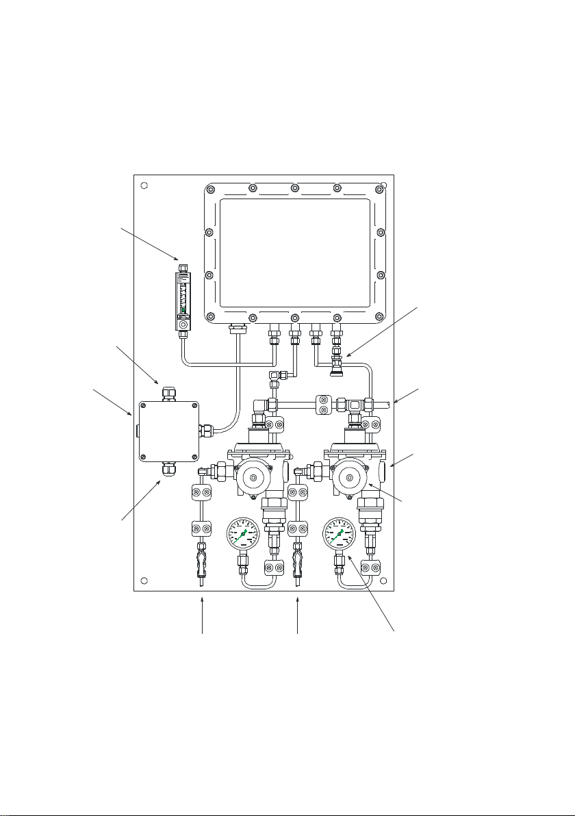
2 View and design
gas-lab Q1
exhaust gas
connection of
safety relief valve
power supply
connection
exhaust gas
connection of
gas-lab Q1
pressure controller
with integrated
safety relief and
safety shut-off valve
data line
connection
pressure gauge of
inlet pressure for gas-lab Q1
calibration gas 1
connection
process gas
connection
calibration gas 2
connection
release button of
safety shut-off valve
ex-junction box
The parameterisation of the evaluation computer defines which gas has to be
connected to which inlet. The process gas is assigned to path 1 and the internal
calibration gas (ultra-pure methane) to path 2. Nitrogen and further calibration
gases are injected via path 3 for performing the basic calibration. The test gas
can either be injected via path 1 or 3.
Not only the sensor housing is installed on the mounting plate, but also
regulators for the inlet pressure of the different gases to be injected, safety shutoff and safety relief valves as well as the EEx-e junction box for the
interconnecting cables (voltage supply, data link to the evaluation computer).
Page 6 gas-lab Q1
Page 15
View and design 2
0987
,
6
5
4
_
3
2
1
Q1
gas-lab
Status
Cal.-
switch
close open
DSS
Gas Quality Meter
Data
interface
Key pad
Calibration
switch
Status LED
Display
The pressure regulators with integrated safety shut-off/pressure relief valves for
the process and calibration gases are necessary, as the maximum absolute inlet
pressure of the gases must never exceed 1,250 mbars. The pressure regulators
have been set by the manufacturer to a control pressure of 80 mbars (gauge).
The integrated pressure relief valve starts to vent at an overpressure of about
110 mbars and above. The safety shut-off valve has been set to a tripping
pressure of 142 mbars (gauge) by the manufacturer.
2.2 Evaluation computer
The housing of the gas-net Q1 evaluation computer is designed as plug-in unit
for a 19”-frame and is available in two housing sizes, i.e. with a mounting width
of 1/3 for up to three process boards or a mounting width of 1/2 for up to six
process boards.
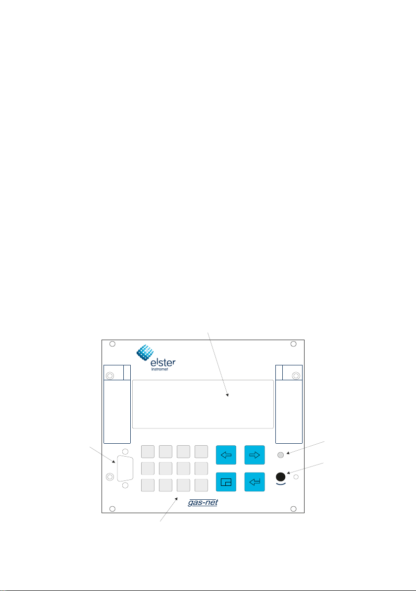
The device front includes one 8x32 characters-LCD, one keypad with 16 keys,
one status LED and the calibration switch. The DSS data interface is also
located on the device front. It serves the connection of a PC or laptop for
servicing purposes.
The following illustration shows, as an example, the front view of a gas-net Q1 in
the narrow design with a mounting width of 1/3:
gas-lab Q1 Page 7
Page 16

2 View and design
Most of the connection possibilities are located on the back of the device. The
following interfaces are always available:
fibre-optics connection for the sensor system
DSfG bus connection
COM2 interface: serial interface according to RS232. In case of devices
with an integrated RDT, the modem is connected to COM2. A different
software variant offers gateway functionality for interfacing a host protocol
instead. In this case, the COM2 interface can be used as protocol channel.
DCF77 interface for connecting a radio clock
24 V DC power supply connection
HSB bus connection (not used)
All process connections are implemented via process boards installed in the
housing. The exact composition of the I/O boards depends on the tasks of each
individual device (number of required output signals, etc.).
The name of the software variant, the version’s number and the checksum for
the identification of the software version can be invoked directly at the device via
the main display of the System module.
The main functionality of the Q1 is measuring the gas quality. The sensor
system is connected via an LMFA1-type process board, which provides 3 digital
and 4 analogue outputs in addition to the fibre-optics connection for the sensor
system.
Furthermore, the following boards can be used:
A multi-functional EXMFE4 input board for the connection of a pressure and
a temperature sensor (PT100) and two digital inputs (NAMUR). All channels
are intrinsically safe (EX-i).
An MSER2 board with 2 serial channels (RS232, RS422 or RS485) for
interfacing communication protocols (e.g. MODBUS).
An MFE11 input board with 8 digital and 3 analogue inputs.
An MFA6 output board with 4 digital and 2 analogue outputs.
Page 8 gas-lab Q1
Page 17
View and design 2
0,63 ATT
LE
LA
D1
D2
D3
I1+
I3+
ISH
DC
LMFA7
SH
GD
DT
VN
VP
PE
DCF7724V
HS-Bus
2
M
O
C
G
f
S
D
CD
RI
TX
RX
SD
DD
SH
DH
internal
Board 3Board 2Board 1
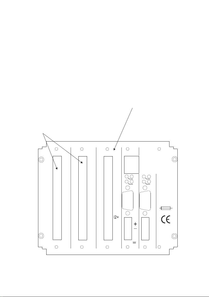
Output board LMFA7 (digital/analog)
LA/LE:
D1-D3:Three digital outputs for digital signals / pulses.
I1-I3: Three analog outputs for measurement output.
optical fibre connection for external I/O expansion
(sensor system connection)
Any input or output board can
be assigned to board locations 1 or 2.
gas-net
All in all, up to 6 process boards can be mounted in the broader housing and up
to 3 boards in the narrow design. Please see Section Fehler! Verweisquelle
konnte nicht gefunden werden. or the Technical Data Section in Chapter 10
for a description of the currently available boards.
The following illustration shows, as an example, a device in the narrow design
with the always existing LMFA7 board.
gas-lab Q1 Page 9
gas-net Q1 rear view (example)
Page 18

Page 19

Operation 3
3 Operating gas-net devices
This chapter’s objective is to give you an understanding of the basic operating
and menu structures of gas-net devices.
As already mentioned, all devices of the gas-net family have a uniform
appearance and a comparable menu structure.
This means for the user: If you have operated a gas-net device once, you will
also be able to operate all other device types without any problems.
According to our philosophy of how to parameterise gas-net devices, they are
adjusted by means of a PC or laptop and not via the operator panel. The device
operation via the operator panel mainly serves the indication of the most
important information on the display. The content of the operator interface on
the display depends on the individual gas-net device type.
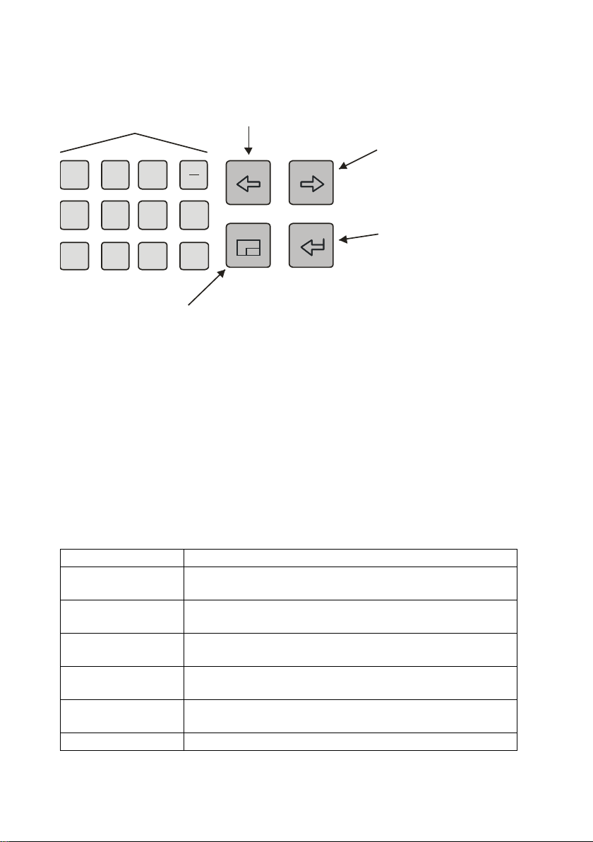
3.1 The keypad
The keypad of gas-net devices consists of a numeric keypad for the entry of
numbers, minus sign and decimal point keys and a group of four navigation
keys. With these keys, you may move within the menu structure and invoke
menus and displays. In some cases you may also trigger actions or change
values via the navigation keys.
The illustration below shows an overview of the keys’ meanings. The exact
context-related meaning of each navigation key will be explained in connection
with the menu structure in Section 3.4.
gas-lab Q1 Page 11
Page 20
3 Operation
1 2 3
4 5 6
,
7 8 9 0
Menu key:
Opens/closes a menu.
When starting from a display this means:
Pressing once opens the current display's submenu listing.
Pressing twice opens the menu listing for branching to other modules.
Pressing three times closes the menu.
Arrow key left:
Previous entry.
Input mode: delete previous character
Enter.
Menu selection.
Enter input mode.
Within input mode:
Accept new value.
Numeric key pad
incl. minus sign
and decimal point
Arrow key right:
Next entry.
Input mode:
Quit input mode without
changing values.
LED status
Meaning
red, blinking
An alarm is pending, i.e. an error has occurred that
influences the gas quality measurement.
yellow, blinking
A warning is pending. That is, an event has occurred
without affecting the gas quality measurement.
green, blinking
A green blinking light appears in the start-up phase after
a mains failure.
red, steady light
An alarm has been pending but is no longer relevant.
It can be removed from the error listing by accepting it.
yellow, steady light
A warning has been pending but is no longer relevant.
It can be removed from the error listing by accepting it.
green, steady light
The device runs error-free.
3.2 Other operating elements: status LED, calibration
switch
The status LED on the front of the device is a three-colour light emitting diode.
The status of this LED indicates whether an error of the gas quality
measurement is pending or has been pending.
Please refer to the table below for the meaning of the individual colours:
Page 12 gas-lab Q1
Page 21

Operation 3
The sequence of the LED status in the above table corresponds to the
sequence the error management keeps to: The system always indicates the
error with the highest priority. A pending error always takes precedence over an
error that is no longer relevant.
The exact meaning of the terms alarm, warning and hint is explained in Chapter
5.3.1.
The calibration switch is on the lower right side of the front panel.
All gas-net devices are furnished with a two-level safety concept: All parameters
being protected by the calibration switch can only be changed if the calibration
switch is open. Such parameters are always modified with a PC or laptop and
the associated parameterisation software GW-GNET+.
Open the calibration switch by turning it anticlockwise as far as it will go. This
first level of the safety concept is important for devices used for legal metrology
and custody transfer. In this case, a seal may officially secure the calibration
switch.
The basic display of the device will automatically be invoked when you close the
calibration switch.
Note: The User lock as the safety concept’s second level consists of one
numerical lock for each of the two contract parties. The user lock is, in contrast
to the calibration switch, implemented via the device software. This means that
the locks are defined via the device parameterisation and opened or closed via
the operator panel. Open locks allow the user to access certain parameters or
actions. All parameters being subject to the user locks can be changed when
both locks are or the calibration switch is open. .
gas-lab Q1 Page 13
Page 22

3 Operation
3.3 Display
The display is an illuminated LCD consisting of 8 lines with 32 characters each.
After approximately 30 minutes without a keystroke, the display’s background
illumination switches off automatically.
3.4 Displays / Menus / Dialogs
One note at the outset:
The following section describes the menu assistance and operation of all gas-
net devices in general.
Where appropriate, individual subjects have been illustrated with examples.
These examples refer to currently available device types. Therefore, it may
happen that a special menu illustrated in an example does not exist in your gas-
net device type.
In accordance with the gas-net concept, however, the operating mechanisms
generally described here function in all devices in the same way.
Each module has a main display in which all important current values are
indicated.
For example: Among others, the gas-net Q1 contains the gas-lab Q1 and
Monitoring modules. The main display of the gas-lab Q1 module shows
the current measurements, whereas the main display of the Monitoring
module indicates the error listing.
The main display of the first module is also the basic display of the device, i.e.
the display that is invoked automatically if there has been no keystroke for about
30 minutes.
For example: The basic display of the gas-net Q1 is the main display of
the gas-lab Q1 module.
A display serves to present values.
If there are more entries than can be made visible at once, little scroll arrows on
the right side indicate whether or not you may scroll upwards or downwards.
Page 14 gas-lab Q1
Page 23
Operation 3
1
“Down” scroll arrow pointing
downwards: Scroll downwards with the rightward
arrow key.
„Up“ scroll arrow pointing
upwards: Scroll upwards
with the leftward arrow key.
Each display which can be shown belongs to a module within the device
software, therefore to a closed functionality. If you see the display of any
module, there are two entirely different targets in the menu structure of the
device. On the one hand a subordinated display / dialogue1 of the shown
module and on the other hand the main display of any module.
To make the navigation within the menu structure as easy and fast as possible,
the menu key is configured as follows:
Unique pressing of the menu key opens up the list of submenues, wich is
provided by the actual module display.
Pressing the menu key again opens up the menu list to branch to any module.
Repeated pressing closes the menu.
The list of submenus of a module is provided according to the current
parameterisation: Menu items that relate to functionalities which are not
parameterised, are not offered at all.
Submenus of a module are either calling other displays or dialogs, in which the
user can manipulate values via control panel.
The menu structure is aborescent:
A subordinated menu item of a module can offer subordinated menu items by
himself.
A Dialog is a display window indicating values that can be changed by the operator.
gas-lab Q1 Page 15
Page 24

3 Operation
Start:
Basic display Gas quality
Menu list of the module Gas
quality.
The hyphen in front of the menu
descriptions indicates that the list
refers to subordinated menus.
In lower levels of the menu structure following contextual menu items are
offered to return to the next upper level:
Menu item Back in a display
Menu items OK / Cancel in a dialog
(OK means acceptance of the changed values too, Cancel means to reject
the changes)
Independent of the menu level which is shown at the moment, with the arrow
keys you can move for- and backward within every menu list and select a menu
item. The selected target is presented in an inverted way, i.e. with green writing
on a black background. Activate the menu item belonging to the selected entry
by pressing the Enter key.
For example: We assume you want to change from the basic display of
the Q1 to the main display of the Monitoring module.
For this, press the menu key first to open the menu window. The first
entry of the appearing listing is selected, i.e. it is backlit in black:
Page 16 gas-lab Q1
Page 25
Operation 3
Module list:
Without hyphens in front
of the menu descriptions
Module list:
Monitoring module
is selected
Since we won’t activate a gas quality menu in our example, but branch to
another module, please press the menu key again.
Now the menu shows a list of all modules the device software contains.
Press the rightward arrow key several times until the module is selected,
that you want to see. In our example it’s the Monitoring module.
Then press the Enter key and the display of the just selected module will
be invoked.
gas-lab Q1 Page 17
Page 26

3 Operation
Tips:
If you have pressed the rightward arrow key too often and went too far
down in the menu selection list, move upwards again by pressing the
leftward arrow key.
If you want to quit an invoked menu selection window without having made
a selection, just press the Menu key as often, until the menu window is
closed.
The selection of some menu items invokes a dialog. These dialogs are displays
in which values can be modified. However, only a few values can be modified
via the operator panel.
In such input dialogs you move from one parameter to another by using the
arrow keys. If a parameter must not be changed (for instance, because it is a
parameter that is subject to the calibration lock, which is closed at that moment),
it will be crossed out in the display.
If you have selected a parameter that can be changed, you may switch into the
edit mode via the Enter key.
In order to render the operation more comfortable, there are different methods of
defining a new value, depending on the type of the value to be changed:
Direct entry of a new numerical value
If you would like to replace individual characters only, delete the characters step
by step from the right using the leftward arrow key. Then enter the new
characters via the numerical keys including decimal point and minus sign.
If it is easier to replace the entire value by a new one, just start with your entry
right away: As soon as you press any numerical key the preset value will be
deleted and overwritten by the new entry.
Quit the edit mode via the Enter key. This initiates a test for consistency: If you
have entered a value that does not make sense in the present context or is not
permissible, you will not be able to quit the edit mode. This way, the user is
forced to correct the value he has entered.
Page 18 gas-lab Q1
Page 27
Operation 3
Start:
Display Single message
Value to be modified is selected.
Edit mode:
The insertion mark is now blinking
behind the value.
In order to quit the edit mode without accepting the change, for instance after an
erroneous entry, just press the rightward arrow key.
In order to quit the entire dialog, invoke the menu and select either OK (the new
values will be accepted) or Cancel (the values will be rejected).
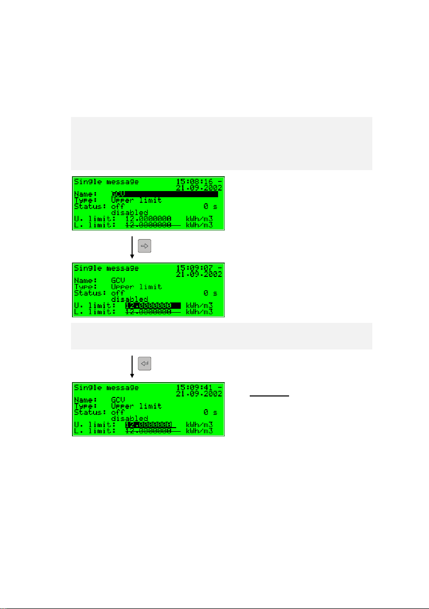
For example:
Change of the lower hint limit for the GCV in the Monitoring module of
the gas-net Q1. After you have invoked the associated menu item, the
following display is visible:
The currently set value is indicated.
Switch to the edit mode via the Enter key.
gas-lab Q1 Page 19
Page 28
3 Operation
1
,2,3,4,5,6,
7,8
,9,0,,,
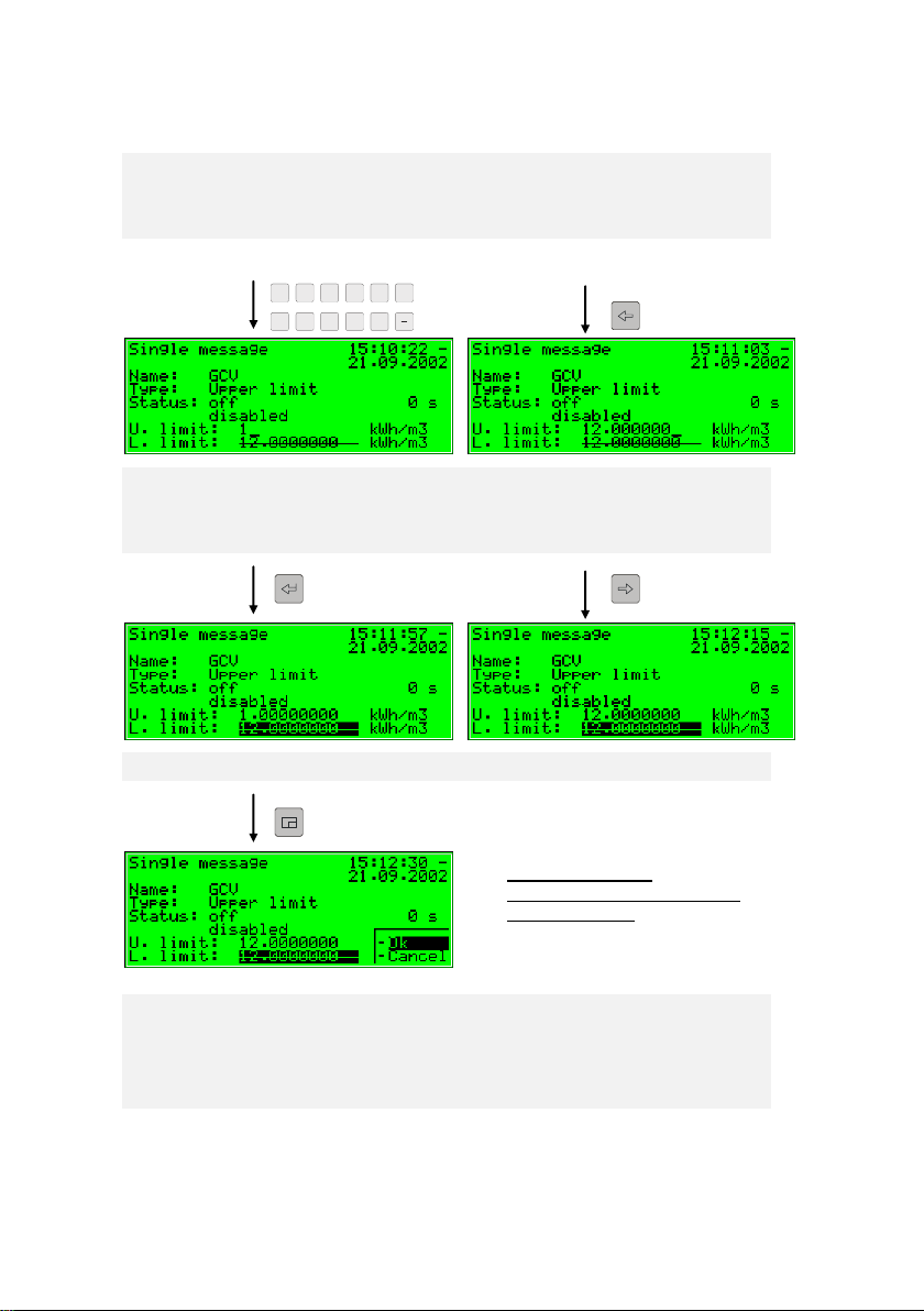
Options on leaving
Acceptance or rejection of the
changed values.
Enter a new value now:
Either directly via the numerical keypad or by deleting individual numbers
from the right using the leftward arrow key and by entering new numbers.
Quit the edit mode by pressing the Enter key. Thereby the new value will
be accepted. If you don’t want that, you should leave the edit mode via
the rightward arrow key.
Invoke the menu now.
If you confirm OK by pressing the Enter key, the new value will be
accepted. To reject the modification, go to Cancel by pressing the
rightward arrow key and afterwards the Enter key.
You will quit the dialog in both cases.
Page 20 gas-lab Q1
Page 29
Operation 3
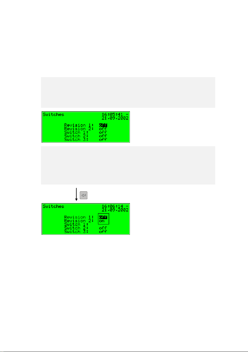
Start:
Monitoring - Switches
Selective list:
All applicable values are offered.
(Here: off and on)
New value by selection from a list
The device software offers a list of possible values in case of editable values the
range of which is restricted to a fixed number of selectable values. Choose a
suitable value from the list via the arrow keys and accept it by pressing the Enter
key.
Example: Opening of the revision switch (Hint: Only possible with user
locks opened!). The state of the revision switches can be changed in the
submenu Switches of the Monitoring module. Therefore go to the related
dialog via the menu items Monitoring - Switches.
In the above illustration the revision switch for both streams is shown as
closed (Revision 1 = off, Revision 2 = off). Let’s assume that you want to
activate the revision switch for the first stream. On entering the display
this switch is already activated, so you can press the Enter key right now
to switch to the edit mode.
gas-lab Q1 Page 21
Page 30
3 Operation
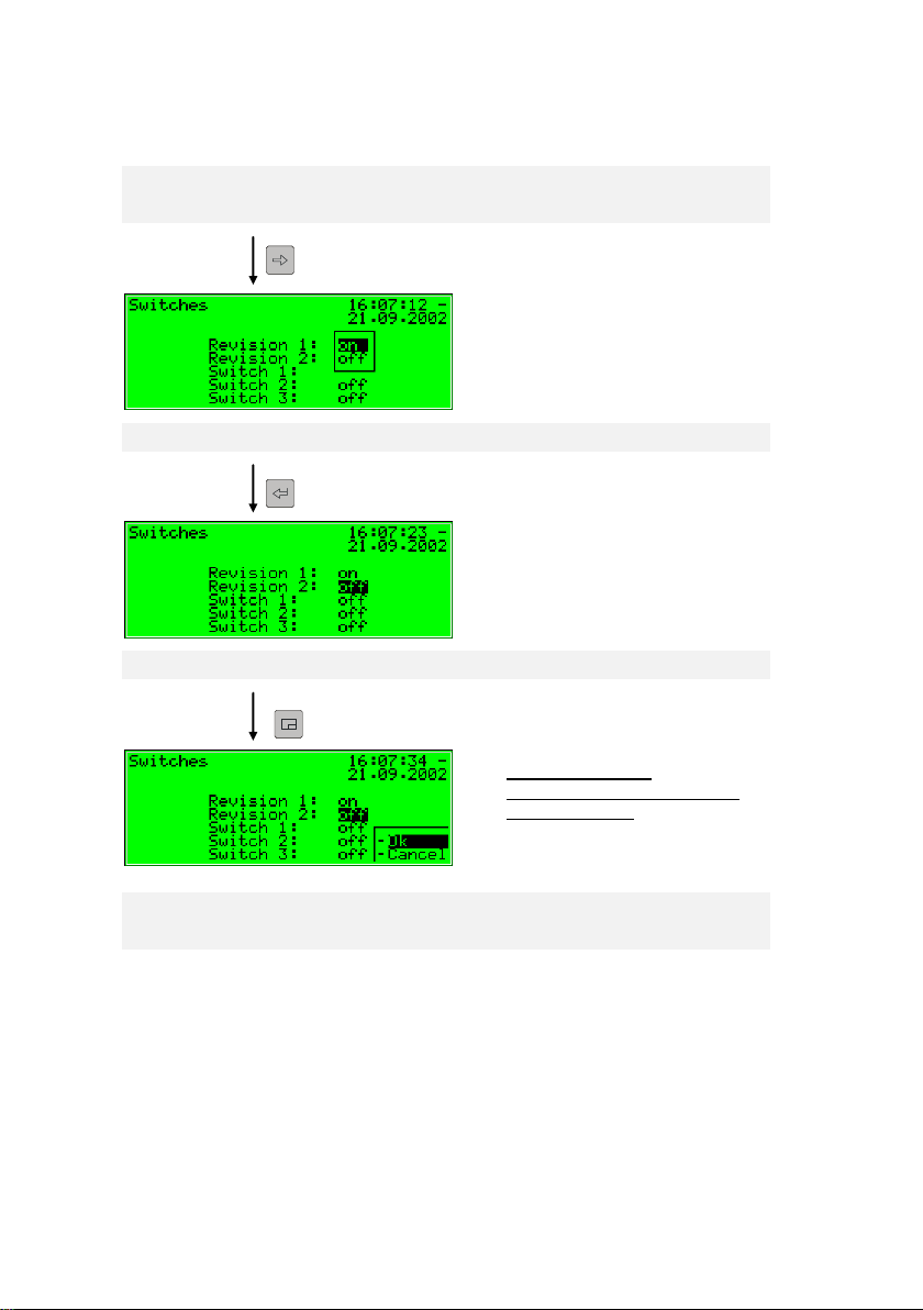
Selective list:
On is selected.
Revision switch 1 is opened now.
Options on leaving
Acceptance or rejection of the
changed values.
Select the desired value via the arrow keys, in our example select on.
The display looks as follows:
Then press the Enter key to leave the edit mode.
Invoke the menu now:
If you confirm OK the new value will be accepted. To reject the
modification, go to Cancel and press the Enter key afterwards.
Page 22 gas-lab Q1
Page 31

Operation 3
Modifying several values at once
Most of the dialogs don’t offer individual values but whole sets of values for
being modified. In such a case, edit the first selected value first. Switch to the
edit mode by pressing the Enter key.
Move to the next value by pressing the Enter key.
Tip: If you don’t want to modify an offered value, skip it by pressing the
rightward arrow key.
Change the value either by directly entering the new value via the numerical
keypad or by selecting a new value from a list.
After having edited all values, press the Menu key. The invoked menu contains
the menu items OK and Cancel. Selecting OK means accepting the modified
values. Selecting Cancel means rejecting the changes. In both cases you will
return to the display you invoked last.
gas-lab Q1 Page 23
Page 32

Page 33

Primer 4
Gas quality error listing
Monitoring error listing
Next listing
4 Primer for impatient operators:
What do I have to do to …?
Notice: The following instructions are based on the assumption that you are in
the basic device menu.
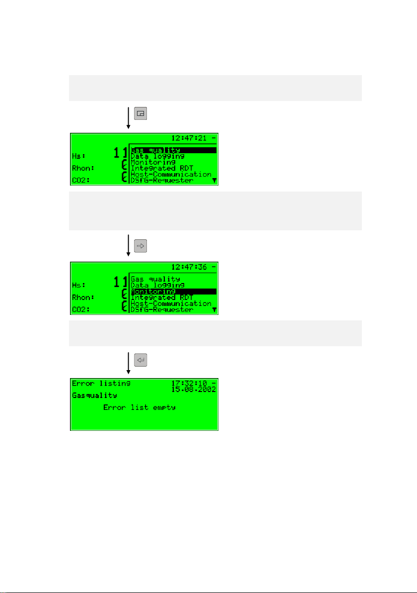
4.1 ... view the gas quality error listing?
If the status LED blinks red or yellow or is steadily illuminated, the error listing
contains alarm or warning entries.
Proceed as described below to view the error listing:
1) Invoke the menu (subordinated items) via the Menu key.
2) Invoke the next Menu (other modules) via the Menu key
3) Press the rightward arrow key until you have selected the Monitoring menu
item.
4) Press the Enter key.
The main display of the Monitoring module is invoked. The error with the
highest priority level is displayed. Scroll through the error listing using the
arrow keys.
5) Proceed to Chapter 5.3.2 should you need more detailed information. If you
would like to accept an error, proceed to the very next chapter.
There may be up to two error listings. In addition to the Gas quality error listing,
an error listing of the Monitoring module’s message processing is also available.
Always switch to the display of the next error listing via the Next listing menu
item. Please refer to Chapter 5.3 for further information on the error listing of the
message processing.
gas-lab Q1 Page 25
Page 34

4 Primer
4.2 … accept the gas quality measurement errors?
Errors can only be accepted and thus removed from the gas quality error listing
if they are no longer pending.
To accept an error, proceed as follows:
1) Open the error listing via the menu as described above in Chapter 4.1.
2) Select the error you want to accept via the rightward or leftward arrow key.
3) Press the Menu key. If the error indicated on the display cannot be
accepted, the first menu item appears as being crossed out: Accept. In this
case, press the Menu key again to quit the menu.
If the error can be accepted, just select Accept and press the Enter key.
The error disappears from the error listing, and the error with next lower
priority level will be indicated on the display.
4) Repeat the steps explained above to accept further errors.
Note: Accepting errors as described above only refers to errors in connection
with the device’s gas quality functions. How to accept messages of the general
message processing (Monitoring error listing) is explained in Chapter 5.3.
Page 26 gas-lab Q1
Page 35

Primer 4
4.3 … check all parameter settings?
The parameterisation of a gas-net device contains too many settings for them to
be conveniently displayed via the operator panel. It is much easer to get a
general idea of the device settings with the aid of the GW-GNET+
parameterisation program and a laptop.
Proceed as described below:
1. Connect the COM interface at the PC to the DSS interface of the Q1
evaluation computer using a parameterisation cable.
2. Start GAS-WORKS on your computer. Activate the communication program
by clicking the Import – Data interface tool in the GW-BASE toolbar.
3. After having successfully started the communication program, you are
linked with the connected device data technology-wise. The window
appearing on your display shows some important basic device information.
4. Select the Tools tab now.
Double-click the Change parameters or the Edit parameterisation entry.
The GW-GNET+ interface will appear on the screen. This is where you can
invoke and check the parameter listings of the individual modules.
Consult the GW-GNET+ online help for details on the operation of the user
interface of GW-GNET+.
Please note: The Change parameters or Edit parameterisation service
programs also offer the option of changing device settings. The current status of
the protection mechanisms (calibration switch / user lock) is of course taken into
consideration. Please refer to the GW-GNET+ comprehensive online help for
further information.
gas-lab Q1 Page 27
Page 36

4 Primer
4.4 … check the input values?
1) The input values are in the System module. Therefore, change to this
module: Press the Menu key twice, then move to the System entry using
the rightward error key and press the Enter key.
2) Then press the Menu key and select the Inputs entry via the rightward
arrow key.
3) Press the Enter key afterwards. The Inputs display will be invoked.
5) Please refer to Chapter 5.4.2 for information on how to proceed further.
4.5 … view and check the outputs?
1) The output values are in the System module. Therefore, change to this
module: Press the Menu key twice, then move to the System entry using
the rightward arrow key and press the Enter key.
2) Then press the Menu key and select the Outputs entry by means of the
rightward arrow key.
3) Press the Enter key afterwards.
The Outputs display will be invoked.
4) Please refer to chapter 5.4.2 for information on how to proceed further.
4.6 … view the archives?
1) Change to the display of the Data logging module: Press the Menu key
twice, move to the Data logging entry using the rightward error key and
press the Enter key.
2) Select exactly the archive information you want to view in the appearing
dialog. By the way it’s more comfortable to view the archives with the PCSoftware. Please refer to Chapter 5.2.2 for a detailed description of the
function.
Page 28 gas-lab Q1
Page 37

Functional description 5
5 Functional description
5.1 Gas quality module
The gas-lab Q1 measuring system is a device for measuring the gas quality of
natural gas. It measures the infrared absorption of hydrocarbons and carbon
dioxide (CO2) and also the thermal conductivity. The following variables are
directly determined based on these measurements:
Hs – Heating value superior, equal to GCV – gross calorific value
standard density Rhos
concentration xCO2 as mole fraction
Further variables are derived from these direct variables, such as:
Wobbe index superior Ws
Methane number MN
Composition of the natural gas consisting of 10 components from C1 to
C8+ as well as N2 and CO2.
Hi – Heating value inferior, equal to NCV – net calorific value
saturated Hs/GCV and Hi/NCV (gas with H2O saturation)
When the device is started, the evaluation computer reads the calibration data
out of the non-volatile memory of the sensor system and starts to measure.
Therefore, make sure to switch on the sensor system either before or together
with the evaluation computer. The measuring operation may only start after the
Q1 has been successfully calibrated (see 5.1.2) and if the process gas is
injected to path 1 with sufficient pressure. The sensor system is furnished with a
pressure switch that detects whether gas is flowing or not.
The sensor system must have reached its operating temperature of about 55 to
60 °C before the device is ready to operate. It may take up to one hour to heat
up a cold device. The evaluation computer waits until the operating temperature
has been reached before indicating valid measurements. View the temperature
of the sensor system in the Process values display (see 5.1.1.2).
gas-lab Q1 Page 29
Page 38

5 Functional description
Indication of the error with
the highest priority level
Time and date
Final values for
GCV – gross calorific value,
standard density,
CO
2
concentration
Important: After the commissioning has been completed, operate
the gas-net Q1 evaluation computer only with the calibration
switch being closed. The calibration switch (the rotary switch on
the front of the device) can be sealed for safety reasons. A closed
calibration switch ensures that actions to be performed by trained
and qualified staff, such as calibrating actions etc., cannot be
started from the device.
5.1.1 Display and operation
5.1.1.1 Main display Gas quality
The gas-lab system measures continuously during normal operation and
constantly calculates actual values for the target variables gross calorific value
GCV, standard density Rhon and CO2 content of the measured gas.
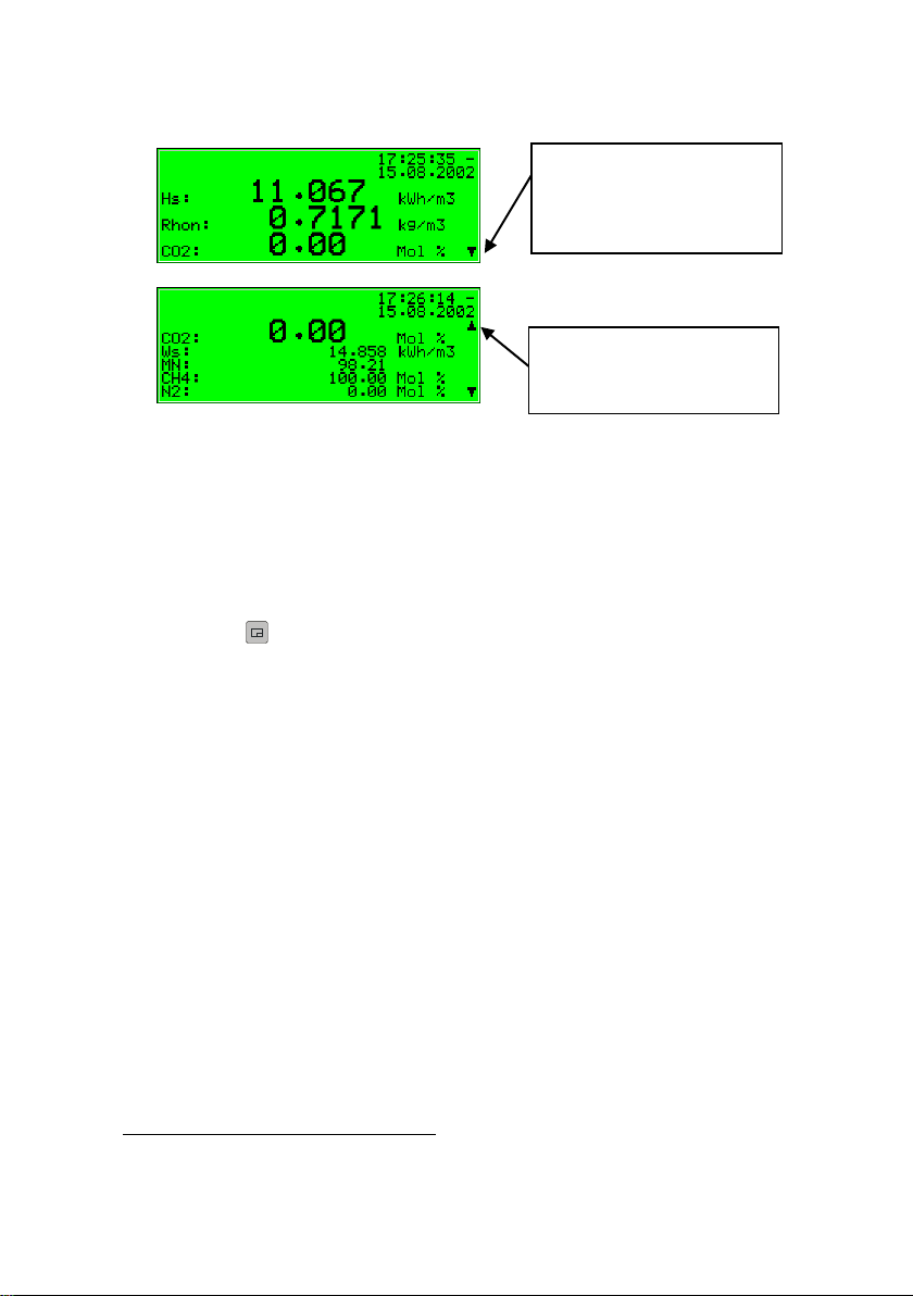
The basic display of the gas-net Q1 evaluation computer supplies a survey of
the measurement status and currently calculated values of the gas analysis.
The first two lines show the pending gas quality measurement error with the
highest priority level on the left as well as time and date on the right.
The last three lines of the basic display indicate the current gas analysis
values GCV, Rhon, and CO2, written in large numbers.
The values shown in the basic display are only current and valid if the
system operates normally in undisturbed conditions. This means that the
measurement is not in the alarm status and a calibration is not carried out.
Page 30 gas-lab Q1
Page 39

Functional description 5
„Down“ scroll arrow pointing
downwards: Scroll downwards with the rightward
arrow key.
The following illustration shows an example of the basic display in case of an
undisturbed operation:
If you scroll downwards in the main display, further derived values will be
indicated as illustrated by the following figures:
A calculated gas analysis with 10 components and the molar percentage of the
C2+ components are indicated in addition to the Wobbe (Ws) and methane
numbers (MN). Hi is the NCV – net calorific value. The variables Hs’, Rhon’ and
CO2’ are corrected values used in the automatic adjustment by means of a
process gas chromatograph (PGC). The values satHon and sat Hun are the
GCV and NCV in case of saturated concentration of H2O for the defined
reference condition. At last the density ratio is displayed.
gas-lab Q1 Page 31
Page 40
5 Functional description
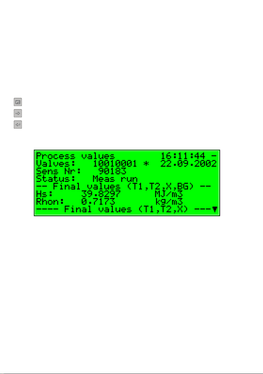
5.1.1.2 Process values display
The gas-net Q1 evaluation computer provides a special display to indicate the
source data measured by the sensor technology, the intermediate values that
have been calculated based on these source values and all determined final
values.
This display is called Process values and is invoked as described below:
1) Invoke the menu in the basic display.
2) Select the Process values entry by pressing the rightward arrow key. Press
the Enter key afterwards.
The Process values display contains too many values to be indicated all at
once. Scroll up or down the display with the arrow keys.
The upper part of the display shows the last valve positioning command sent by
the computer to the valve set as bit string (10010001). Also the number of the
current measurement is displayed, which is consecutively numbered. Furthermore the current state of measurement is indicated.
All other values are intended for service and maintenance purposes. If you have
questions for them please contact Elster.
Page 32 gas-lab Q1
Page 41

Functional description 5
5.1.2 Calibration
Each gas-lab Q1 measuring system has been calibrated when being delivered,
i.e. the device has been calibrated by the manufacturer. During operation an
automatic calibration with methane (1-point calibration) is carried out
periodically. During the routine testing of the device after one year, we
recommend to perform a manual basic calibration with nitrogen, methane and
two other calibration gases (3-point calibration).
5.1.2.1 1-point calibration / automatic calibration
Precondition for a successful completion of a 1-point calibration is that the
methane is properly connected on gas path 2 (see Cylinder change 5.1.4).
For this purpose the cylinder regulator must set be to approx 2 bars and the
precision pressure regulator (M2R) of the second gas path must be set to about
80 mbars. If the methane cylinder is not already opened, open it now and do a
purging right after it (see 5.1.5). Also the corresponding shut-off valve must be
opened.
It is not necessary to open the calibration switch at the gas-lab Q1 for this
calibration type.
An automatic 1-point calibration with methane can be carried out during normal
measuring in the following conditions:
In a fixed, configurable cycle every 1, 2, 3, 4, 5 or 6 days or 1, 2, 4, 8 or 12
weeks on a specified day at xx o’clock, typically every 7 days.
After a configurable time in hours after each switching on of the supply
voltage for the evaluation computer or sensor system, typically 12 hours
later.
After a configurable time in hours after each manual purge of a gas path,
typically 12 hours later.
After a configurable time in hours after errors that may affect the
measurement have been cleared, for instance Pressure disturbed
evaluation computer (A607), typically 12 hours later.
gas-lab Q1 Page 33
Page 42

5 Functional description
Manually by performing the 1P-cal. start command in the Calibration menu
what is described below.
By setting a parameterised digital input.
By means of a DSfG command.
The following reactions of the evaluation computer are indicating the status of
the 1-point calibration:
Via measurement outputs and on the controller’s basic display the last valid
gas quality values are maintained provided any values are available.
The basic display shows 1P-cal.
during calibration.
A Revision message will not be
generated.
If you want to abort the function prematurely, do so by keeping to the following
instruction sequences:
Invoke the menu from the basic display and select Calibration.
Confirm the selection and invoke the menu again.
Then select Cal. Cancel and confirm the selection
The gas-lab Q1 terminates the calibration process and returns to normal
operation.
Page 34 gas-lab Q1
Page 43

Functional description 5
The process will be aborted automatically if an alarm occurs during calibration.
Afterwards, the gas-lab Q1 uses the previous calibration data, provided such
data exists.
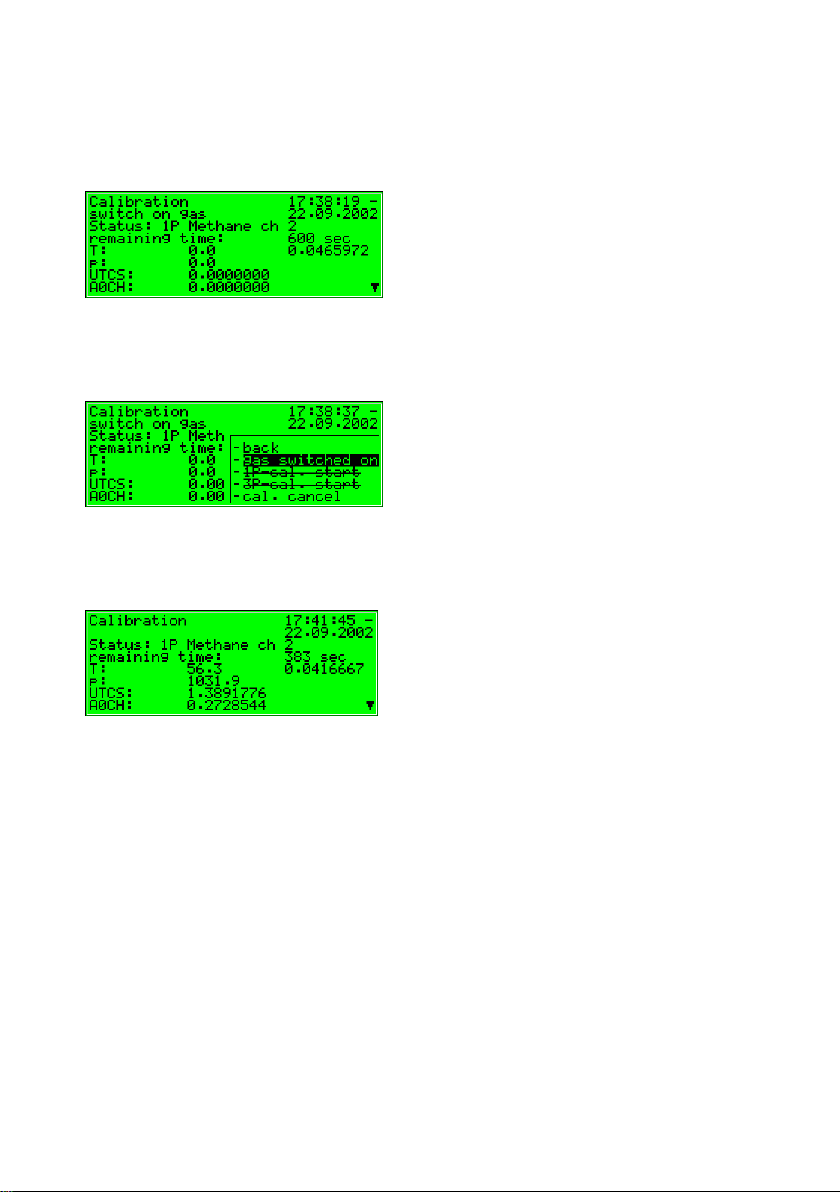
To manually start the 1-point calibration, do so by keeping to the following
instruction sequences:
Invoke the menu from the basic display select Calibration and confirm.
Measurement values of different sensors are displayed now.
By pressing the menu key again, the following submenu appears. Select the
menu item 1P-cal. start and confirm.
gas-lab Q1 Page 35
Page 44
5 Functional description
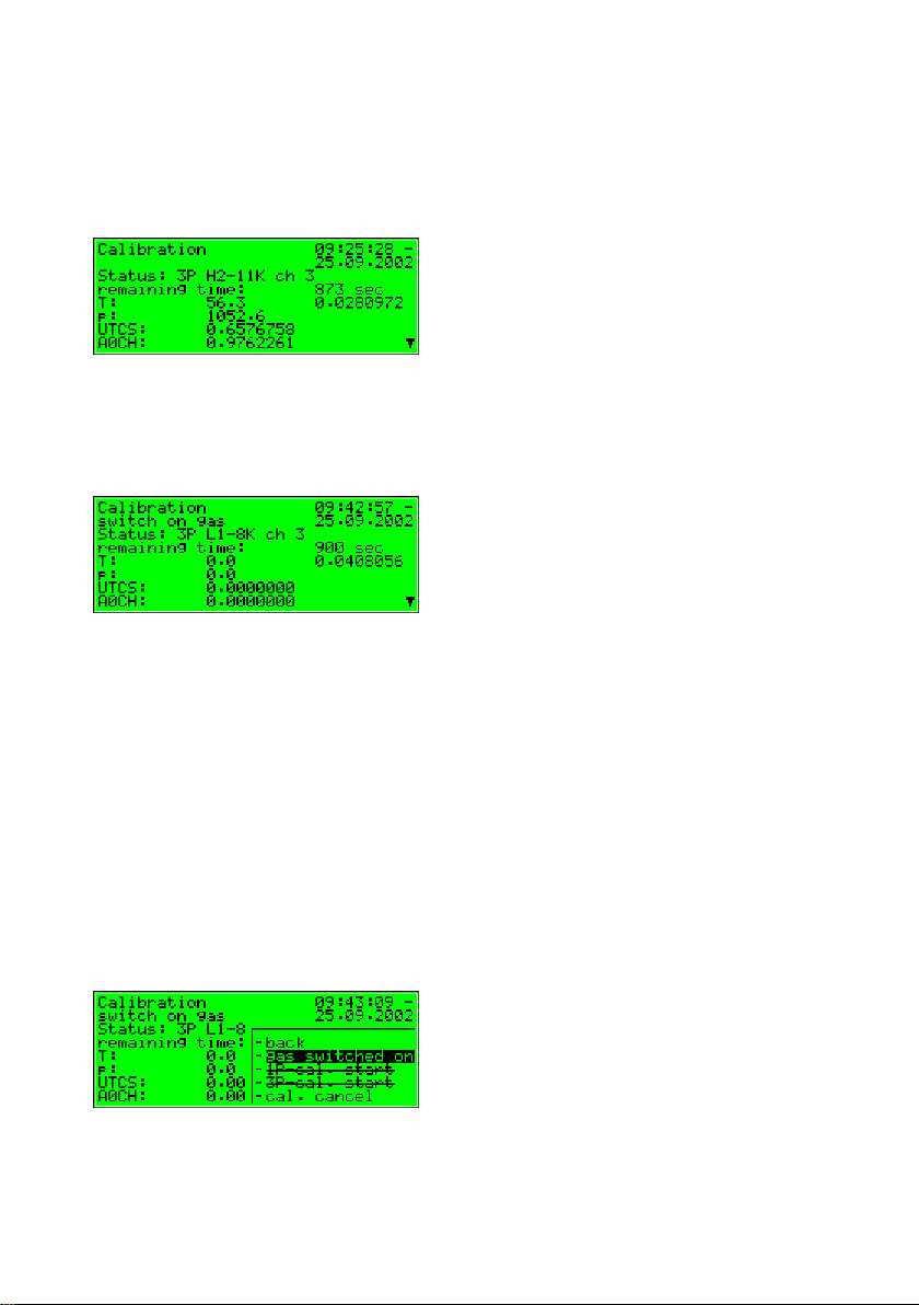
Now the actual status of the 1-point calibration is indicated on the display. Here
e.g. the required operation – switch on gas (methane gas path 2)
In case the methane is properly connected to gas path 2 (see beginning of
chapter), please invoke the menu and select the menu item gas switched on.
After confirming the calibration with methane proceeds automatically, whereas
the remaining time is displayed.
This process starts after approx. 2 minutes for purging and lasts for 10 minutes.
Page 36 gas-lab Q1
Page 45
Functional description 5
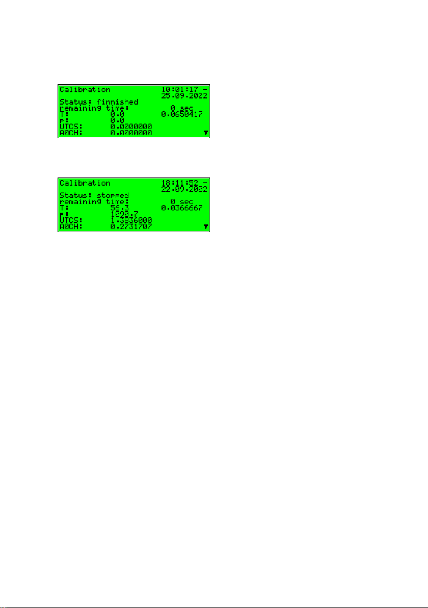
The end of calibration is indicated by the following display:
Then the display changes to the following condition (same as before starting):
After the 1-point calibration is finished, the sensor system automatically injects
the process gas and starts measuring.
The new correction values determined during the calibration are written to the
calibration archive.
We also recommend observing the deviations of the automatic 1-point
calibration in the quality archive.
If these values are getting too high, a new basic calibration should be
performed.
gas-lab Q1 Page 37
Page 46
5 Functional description
5.1.2.2 Basic calibration / 3-point calibration
Such a basic calibration is generally performed on the occasion of the yearly
routine testing. Trained and qualified staff must perform the basic calibration.
Although it runs automatically, the process steps are supported via the operator
panel of the evaluation computer.
The calibration switch at the gas-lab Q1 must be open to facilitate a basic
calibration.
The following reactions of the evaluation computer are indicating the status of
the 3-point calibration:
During the parameterisation of the gas-lab Q1 you may determine whether
or not the last valid gas quality values shall be maintained via measurement
outputs and on the basic display of the computer during this time.
The display shows 3P-cal. during
calibration.
A Revision message will be
generated.
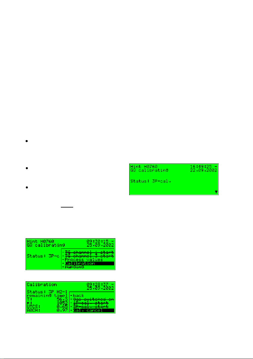
If you want to abort the function prematurely, do so by keeping to the following
instruction sequences:
In case you are not in the Calibration module: Invoke the menu from the basic
display, select Calibration and confirm the selection.
Invoke the menu and then select Cal. Cancel.
Page 38 gas-lab Q1
Page 47

Functional description 5
By confirming the selection the gas-lab Q1 terminates the calibration process.
The process will be aborted automatically if an alarm occurs during calibration.
Afterwards, the gas-lab Q1 uses the same calibration data as before, provided
such data exists.
The basic calibration consists of the following steps:
1. Preparation
2. Zero point adjustment with nitrogen via path 3
3. Calibration with methane (1. calibration gas) via path 2
4. Calibration with H2-11K (2. calibration gas) via path 3
5. Calibration with L1-8K (3. calibration gas), via path 3
optional with a binary gas mixture (5% CO2 in methane)
1. Preparation
For successful completion of a 3-point calibration, the methane cylinder, also
used for the automatic calibration, has to be connected correctly to the second
gas path (see 5.1.4). The cylinder regulator must be set to approximately 2 bars
and the precision pressure regulator (M2R) of the second gas path to about
80 mbars.
If the methane cylinder has not been opened yet, open it and perform a purge
first (see 5.1.5).
Furthermore nitrogen and two other calibration gases (H2-11K, L1-8K or binary
mixture) will be connected one after another to the third gas path during the
calibration process. Since they are not needed for normal operation, they have
to be connected first.
The nitrogen is needed first, so his connection to the third gas path is described
next and stands also for the other two gases.
gas-lab Q1 Page 39
Page 48

5 Functional description
As no precision pressure regulator (M2R) has been installed on the mounting
plate for the third path normally, mount an additional precision pressure
regulator behind the cylinder regulator of the nitrogen cylinder for you to adjust
the operating pressure of the sensor system to approximately 80 mbars. This is
done in the following way:
Make sure that the nitrogen cylinder has been turned off and the cylinder
regulator is set to zero.
Connect a precision pressure regulator to the cylinder regulator of the
nitrogen cylinder and attach a high-pressure tube to the precision pressure
regulator.
Open the precision pressure regulator, so that some gas can flow off in the
next step, whereby the high-pressure tube is purged.
Open the nitrogen cylinder. The cylinder regulator must be set to about 2
bars.
Set the precision pressure regulator to approx. 80 mbars
Connect the high-pressure tube to the third gas path of the sensor system
finally
For performing a basic calibration the gas-lab Q1 needs to know the exact composition of the used calibration gases also.
For that purpose the gas analysis of the used calibration gases has to be
entered in the actual parameterization.
Support in changing an existing parameterization is given in chapter 6.2 and
regarding the affected parameters in chapter Fehler! Verweisquelle konnte
nicht gefunden werden. under periphery.
Page 40 gas-lab Q1
Page 49

Functional description 5
2. Zero point adjustment with nitrogen
While being in the gas quality main display press the menu key and activate the
Calibration command in the invoked menu.
A display with measurements of the different sensors appears.
By pressing the menu key again, the following submenu appears.
Select the menu item 3P-cal. start and confirm.
Now the actual status of the 3-point calibration is indicated on the display. Here
e. g.: The required operation – switch on gas (nitrogen channel 3)
gas-lab Q1 Page 41
Page 50

5 Functional description
In case the nitrogen is properly connected to gas path 3 (see beginning of
chapter), please invoke the menu and select the menu item gas switched on.
After confirmation the zero point adjustment with nitrogen proceders
automatically.The process takes about 25 minutes. Meanwhile the display
shows the remaining time. It will not count down beforet 2 minutes of flushing
time.
3. Calibration with methane (1. calibration gas)
Now the prepared methane has to be switched on, which the following display
indicates:
Please invoke the menu and select the menu item gas switched on.
Page 42 gas-lab Q1
Page 51

Functional description 5
After confirming the calibration with methane (1. calibration gas) runs
automatically. The adjustment starts after approx. 2 minutes for purging and
lasts for 15 minutes, whereas the remaining time is displayed.
Meanwhile turn off the nitrogen cylinder and remove the tube on both sides.
(Caution: Unpressurise the line first!).
Furthermore you can prepare the second calibration gas (H2-11K) on the third
gas path (see step 1. Preparation) When the calibration process with methane
(1. calibration gas) is finished, the following display appears:
4. Calibration with H2-11K (2. calibration gas)
Now the prepared H2-11K has to be switched on. Please invoke the menu and
select the menu item gas switched on.
gas-lab Q1 Page 43
Page 52
5 Functional description
After confirming the calibration with H2-11K (2. calibration gas) runs automatically, whereas the remaining time is displayed.
The adjustment starts after approx. 2 minutes for purging and lasts for 15
minutes. When the calibration process with H2-11K (2. calibration gas) is
finished, the following display appears:
Now turn off the H2-11K cylinder and remove the tube on both sides.
(Caution: Unpressurise the line first!).
5. Calibration with L1-8K or binary gas mixture (3. calibration gas)
Now the prepared L1-8K or binary gas mixture has to be connected. (see step 1.
Preparation)Then the prepared 3rd calibration gas is started by opening the
menu and selecting the menu item gas switched on.
Page 44 gas-lab Q1
Page 53

Functional description 5
After confirmation the calibration with the 3rd calibration gas (L1-8K or a binary
gas mixture) proceeds automatically. The remaining time is indicated on the
displayed. In any case “L1-8K” is shown on the display, even if you use a binary
gas mixture instead.
The adjustment starts after approx. 2 minutes for purging and lasts for 15
minutes, whereas the remaining time is displayed
The end of calibration is indicated by the following display:
Then the display changes to the following condition (same as before starting):
After the basic calibration is finished, the sensor system automatically switches
back to the process gas and starts measuring.
Now turn close the L1-8K or binary gas mixture cylinder and remove the tube on
both sides.
(Caution: Unpressurise the line first!)
gas-lab Q1 Page 45
Page 54

5 Functional description
5.1.3 Test gas injection
The injection of test gases serves to check the gas quality meter with a known
gas or to measure unknown gases on a non-routine basis.
The following reactions of the evaluation computer are indicating the status of
the test gas injection:
Via measurement outputs and on the controller’s basic display the last
valid gas quality values are maintained provided any values are
available.
A Revision message will be generated.
Please proceed as described below:
1. Decide whether you like to inject the test gas via gas path 1 or 3.
2. Make sure the test gas cylinder is closed and the cylinder regulator is set to
zero. Set the associated precision pressure regulator to zero. Connect the
outlet of the precision pressure regulator to the first or third gas path of the
sensor system using a high-pressure tube. When using gas path 1, make
sure the process gas, which is also connected to this path, has been shutoff tightly and thus is not able to affect the measurement by contaminating
the test gas.
3. Open the test gas cylinder. The cylinder regulator must be set to about
2 bars.
4. Set the precision pressure regulator to approx. 80 mbars.
5. Now purge the first or third gas path (see 5.1.5).
Page 46 gas-lab Q1
Page 55

Functional description 5
6. Press the Menu key while being in the gas quality main display and activate
the TG path 1 start or TG path 3 start command in the invoked menu.
7. Now, the sensor system will be purged with test gas for about 2 minutes.
Afterwards, the measurement begins. The measurement results are shown
in the main display.
8. To finish the test gas injection, press the Menu key and activate the TG
path 1 end or the TG path 3 end command.
9. Now please turn off the test gas cylinder and remove the tube on both
sides.
(Caution: Unpressurise the line first!).
A running test gas injection will be aborted automatically after 1 hour (which can
be parameterised), and process gas will be injected instead.
When gas path 1 was used, make sure that after the test gas injection the
process gas is reconnected and opened to this path. Otherwise the test gas is
handeled as process gas and the measurement results are mapped incorrectly.
gas-lab Q1 Page 47
Page 56

5 Functional description
5.1.4 Cylinder change
Different gases must be available in the plant for calibration and measurement
tasks. Therefore it might be necessary from time to time to connect another gas
cylinder to a gas supply connection of the gas-lab sensor housing; for instance,
if the pressure of the methane cylinder is insufficient for the 1-point calibration to
be carried out.
To remove an existing cylinder, proceed as follows:
1. Close the old cylinder at the main valve on top of the cylinder and
unpressurize the connected gas line. You possibly have to wait until the
remaining gas has been used up or use an available venting possibility
(preferably low pressure side).
2. Remove the cylinder connection from the cylinder and close the cylinder
with the corresponding nut.
3. Place the protective cap on the cylinder and fasten it..
4. Not until now detach the protection against falling down (safety chain or
clamp) and remove the cylinder.
Page 48 gas-lab Q1
Page 57

Functional description 5
To connect a new cylinder, proceed as follows:
5. Secure the new cylinder with a chain or clamp against falling down at first.
6. Remove the protective cap from the cylinder by unscrewing it.
7. Make sure that the main valve on top of the cylinder is closed.
8. Remove the nut from the valve connection now.
9. Make sure that the pressure reducing valve and the shut-off valve of the
high-pressure regulator or cylinder pressure regulator to be connected are
closed. Close the pressure reducing valve by unscrewing its setting screw.
10. Now connect the cylinder connection of the high-pressure regulator or
cylinder pressure regulator to the valve connection of the gas cylinder.
11. Open the main valve of the gas cylinder and adjust the outlet pressure of
the high-pressure regulator or cylinder pressure regulator to the operating
pressure needed by the sensor system for the gas stream you are
preparing just now. (i.e.: 1 – 5 bars if in front of an additional low pressure
regulator (M2R) or only 80 mbars if directly connected to gas path 3 of
sensor system)
To purge the high-pressure or cylinder pressure regulator, proceed as follows:
12. Close the main valve of the gas cylinder and wait until the high-pressure
regulatoror cylinder pressure regulator is almost drained, i.e. until the outlet
pressure has almost dropped down to 0 bar. Now open the gas cylinder
again.
13. Repeat this draining and filling of the high-pressure regulator or cylinder
pressure regulator twice to ensure that the regulator’s dead volume does
not contain gas from the previous use or air.
14. Pay attention to the fact that the gas cylinder must be open finally to make a
calibration or measurement possible.
gas-lab Q1 Page 49
Page 58

5 Functional description
5.1.5 Purging
After having exchanged a gas cylinder with a flammable content, always make
sure that no air gets into the sensor system. This is why a purge must be
initiated manually after each cylinder change. This also applies if air may have
entered in a gas path connected to the sensor system.
The following reactions of the evaluation
computer are indicating the status of the
test gas injection:
The last valid gas quality values are maintained via measurement outputs,
provided any values are available at all.
The Revision status will not be indicated.
Proceed as described below:
1. Connect the gas cylinder to the relevant gas path. Set the pressure of the
cylinder regulator output to 1 - 5 bars and the pressure of the downstream
precision pressure regulator to 80 mbars.
2. Press the key while menue being in
the main display, select the purging
command and confirm it by pressing
the key enter.
3. Gas-channel 1 appears on the
display.
Page 50 gas-lab Q1
Page 59

Functional description 5
4. Press the Enter key again. The
following selection list appears:
Select the gas path you would
like to purge via the arrow keys.
Confirm your selection by
pressing the enter key again.
5. Press the menu key now and start the purge with OK or quit the dialog via
Cancel.
6. The purge lasts for about 7
minutes. The display shows
purging.
After the purge has been finished automatically, the gas-lab Q1 starts
measuring the process gas again.
gas-lab Q1 Page 51
Page 60

5 Functional description
5.1.6 Revision
The gas-lab Q1 sets the revision status in case of a zero point adjustment, a 3point calibration or a test gas injection.
A set revision status means that the gas quality is not measured under normal
and proper operating conditions.
All entries in the interval archive are marked with the Revision status note.
Furthermore, the Revision switch open hint will be generated and entered in the
error listing and logbook.
The termination of the revision operation results in the ending of the Revision
switch open hint with an entry in the logbook and induces a last entry marked
Revision in the interval archive.
The gas quality measurement runs normally again.
Page 52 gas-lab Q1
Page 61

Functional description 5
5.2 Data logging module
5.2.1 Function
The gas-net Q1 evaluation computer is always equipped with an integrated data
logging function. The responsible Data logging module, however, provides only
the data logging service. The actual data to be logged is generated by other
modules of the module group.
When parameterising the Data logging module, you only have to define which of
the available archive groups shall actually be logged and which storage depth
shall be applicable. All archives defined in that way are designed as ring
storage. The data logging depth determines how many entries an archive is able
to write at most. If an archive is full, the respective oldest entry will be
overwritten by each new entry.
The following sections list the types of archive groups each gas-net Q1 module
provides:
Gas quality module:
The gas quality module provides 3 archive groups:
The PTB archive logs the billing-relevant data, which consists of the gross
calorific value GCV, CO2 content and status of the measurement system.
The data is recorded every 15 minutes. The PTB archive has a size of 180
days.
The Interval archive logs the gross calorific value GCV, the standard
density Rhon, the CO2 content and the status of the measuring system.
The data is logged at the full hour and when an error occurs. The Interval
archive has a size of about 60 days.
The Quality archive logs 6 quality factors during each 1-point calibration.
These factors provide information on the corrections that have been made
during the individual calibrations with methane. The Quality archive has a
depth of 365 entries.
gas-lab Q1 Page 53
Page 62

5 Functional description
Monitoring module:
The Monitoring module facilitates the compilation of process value archives
(archives with any measurements or count values). Moreover, it runs the gas
quality measurement’s error logbook. The beginning and ending of all error
types (alarm, warning, hint – see Chapter 5.3.1) are entered in the listing in clear
text and together with a time mark. There is an additional, separate error listing
for internal message processing, if this function is used. This error listing can
also be logged.
System module:
The System module runs a parameter change archive (changed settings
archive) ), in which changes of the parameterisation are logged.
If individual parameters are modified, the old and new values will be logged in
addition to the time mark. The module to which the changed parameter belongs
is also displayed.
A completely new parameterisation will be entered in the changed settings
archive as New parameterisation via the data interface when the calibration
switch is open. A change of the parameterisation’s operational part is marked as
New operational parameterisation.
Note: The archive depth, exact composition and order of archives can be
configured by the user via the parameterisation. However, when changing the
archive structure, you have to delete the old archives already existing in the
device.
The devices have already been provided with a pre-defined archive structure
corresponding to the common requirements before delivery.
Page 54 gas-lab Q1
Page 63

Functional description 5
Current calendar time
Input mask for selection of the
archive information to be
indicated in the next step.
}
5.2.2 Display and operation
Main display (Data logging module)
All existing archive entries can be made visible at the operator panel.
The main display of the Data logging module consists of a mask in which you
may choose the data you want to view more closely. The following illustration
shows an example:
After the main display of the Data logging module has been invoked, the most
recent entry of the first channel of the first archive group is always indicated first.
Choose the archive information you would like to view :
The archive type is selected at the
beginning, i.e. it is backlit in black.
Press the Enter key to get into the
edit mode.
A list opens up from which you may
choose the desired archive type via
the arrow keys.
gas-lab Q1 Page 55
Page 64

5 Functional description
2
Afterwards, confirm your choice by
pressing the Enter key. The next field
is selected.
Specify the archive channel you want
to view in detail in the next selection
field. Several possibilities are offered,
depending on the archive group type
you have selected in the first step.
For instance, for the PTB archive type you may choose between GCV, CO2
and Status2.
You may specify the point of time to be
filtered by changing day, month, year
and time one after the other.
You get into the edit mode (as
indicated by the black underscore) for
each respective field by pressing the
Enter key and are thus able to specify
date and time step by step.
Use the arrow- or number keys to set the date and time. Confirm your entry
via the Enter key
Status stands for a bit string that provides an overview of the status of the gas quality
measurement system according to the DSfG Regulations. The meaning of the individual
bits is defined in the DVGW documentation Technische Spezifikation für DSfG-
Realisierungen (see Bibliography).
Page 56 gas-lab Q1
Page 65

Functional description 5
3
The next field is selected. Select the
entry you want to view via the
ordinal number3 in this field.
As there is an unambiguous relation between date and ordinal number, the
associated ordinal number is indicated automatically after the date has
been entered (see above).
If you enter a different ordinal
number, the date in the second line of
the selection mask will be adjusted
automatically. (See diverent times in
the example)
Invoke the selected archive via the menu View (see next section).
Each individual measured variable of an archive group, which is filed by a device, has an
ordinal number according to the DSfG Regulations. The sequence of the ordinal numbers
is arranged in such a way that the very first archive entry receives the number 1. The
ordinal number for each further entry is increased by one.
For instance, ordinal numbers are needed for the polling of archive data via DSfG.
gas-lab Q1 Page 57
Page 66

5 Functional description
The "up" and "down" scroll arrows
indicate that you may view even more
archive entries.(Scroll with leftward or
rightward arrow key.)
Archive entry with ordinal no. 110
Subordinate menu items (Data logging module)
View
By activating the View menu item, you
invoke the display of the archive channel
you have selected in the main display.
The archive type and current time are shown in the first two lines. Each entry is
provided with a time mark. Name, value and unit of the logged data are shown.
Exactly two successive archive entries are displayed at once.
For example (interval archive gas quality, GCV channel):
Return to the main display, i.e. to the
selection mask for viewing archives, via
the subordinate menu item Back. To be
able to switch to the entries of other
channels with the same time mark,
exactly the same mask you have specified before will be invoked.
Tip: The archive presentation on the display is limited due to a lack of
space. To analyse larger archive areas it is much more practical to read the
archives out of the device and into a PC or laptop before, for example via
the data interface by means of the GAS-WORKS module GW-REMOTE+.
View the data afterwards in a table or as diagram by means of the GW-XL+
program.
The configuration of the data logging function is more comfortable via the
PC-Software and therefore not described here. See the Online-Help for
further questions.
Page 58 gas-lab Q1
Page 67

Functional description 5
5.3 Monitoring module
5.3.1 Function
The Monitoring module basically performs the signalling and monitoring tasks of
the device:
Monitoring the gas quality measurement for errors.
The error listing serves the user to analyse and remove gas quality
measurement errors and to be able to understand the history of the course
of error.
Monitoring of any logged measurements.
Signalling of operating states.
Log-on of process value archives (archives for measurements and count
values which can be used to replace a recording instrument, for example)
Switching functionality
5.3.1.1 Monitoring the gas quality measurement and error listing
There are three different kinds of gas quality measurement errors, which are
also treated differently by the error management:
An Alarm is generated if a gas quality-relevant error has occurred.
Beginning and end of an alarm are entered in the associated error listing
together with a time mark (<Alarm> begins/ends).
If an alarm is no longer pending, i.e. it is no longer relevant, it can be
accepted at the device and thus removed from the error listing.
A Warning is generated if a gas quality-relevant variable is affected but
does not influence the result of the gas quality measurement. If a warning is
no longer pending, i.e. it is no longer relevant, it can be accepted at the
operator panel of the device and thus removed from the error listing.
gas-lab Q1 Page 59
Page 68

5 Functional description
A Hint is generated if a measurement violates a hint limit specified by the
operator (upper/lower hint limits for gas quality data).
In addition, a hysteresis can be defined to avoid fluttering messages when a
measurement fluctuates around a limit value. The message <Hint limit
begins> will then be generated or removed only if the measurement is not
within the hysteresis range.
A hint will also be generated if an event occurs which has no influence on
the gas quality measurement (e.g. Calibration switch open).
The beginning of a hint is entered in the error listing together with a time
mark. Hints cannot be accepted and disappear from the error listing
automatically after they have ended.
A complete list of all errors together with their classification is included in the
annex to this documentation.
The status LED of the device indicates the message with the highest priority
level (pending alarm, pending warning, unaccepted alarm, unaccepted warning)
according to the table in Chapter 3.2.
5.3.1.2 Measurement indication
In addition to monitoring measurements for hint limits and gradients, the device
may also file up to 32 measurements. For each defined measurement the
minimum and maximum values measured since the last reset are indicated. The
operator can view these values together with the associated time marks on the
display.
Page 60 gas-lab Q1
Page 69

Functional description 5
5.3.1.3 Message processing; messages and groups
Note: The message processing function of the monitoring module runs
completely independent of the device’s gas quality measurement monitoring.
Therefore, this functionality of the monitoring module is provided with a separate
error listing and an own logbook.
Please take into consideration that the rules of this message processing differ
considerably from those of the monitoring of the gas quality measurement (see
above); for instance, the acceptance mechanism is totally different. If you know
the DIN 19 235 standard (Signalling of operating conditions), you may be
familiar with many terms mentioned in the description below. The message
processing of the Q1 is oriented towards this standard wherever it has proved to
be useful and possible with regard to the monitoring function.
The message processing of the Q1 may manage up to 64 messages defined by
parameterisation. In principle, there are different types of conditions to be
signalled which can be mapped to such a message. The operator himself
defines the events that shall result in messages within the message processing
by parameterising the device.
First, the status of a digital message input (set/not set) can be evaluated as
message. Messages generated by the device itself during operation may also
be integrated in the message processing, such as a gas quality alarm.
Second, measurements can be monitored for limit violation. This applies to
measurements supplied via analogue inputs or measured values generated
internally. In addition to monitoring upper and lower hint limits, it is also possible
to monitor gradients. The gradient monitoring observes measurement changes
within defined time ranges: If the difference between the highest and lowest
values of a measured quantity exceeds the defined maximum value within a
parameterised time range, the condition for generating the message Hint limit
gradient has been met.
Note: All single messages referring to measurements are also pending if the
associated input value is regarded as being disturbed.
gas-lab Q1 Page 61
Page 70

5 Functional description
measured
value
Lower hint limit
occurs
Lower hint limit
ends
Lower hint limit
Hysteresis
range
Upper hint limit
Hysteresis
range
Upper hint limit
ends
Upper hint limit
occurs
There are two different methods of avoiding fluttering messages:
1. Hysteresis monitoring (only in case of measurement monitoring)
A hysteresis can be defined to avoid fluttering messages if a measurement
fluctuates around a limit value. The message <Hint limit begins> will then
be generated or removed only if the measurement leaves the hysteresis
range.
2. Considering a minimum pending time
When a minimum pending time is evaluated, a message is only considered
pending if the condition to be signalled (set digital input, hint limit violation,
etc.) is pending longer than the minimum pending time lasts.
The target of the message-processing concept is to combine messages in
groups. Owing to group monitoring and evaluation the monitoring itself remains
clearly understandable even if the amount of signals is rather large.
The user himself may define the scope of the associated error listing. Via the
device parameterisation he determines for each message whether a single
message shall be entered in the error listing and logbook of the monitoring
module. Only if this is the case, the message will be entered in the error listing
as soon as it begins. There is no acceptance required for single messages; they
are automatically removed from the error listing when they end.
Page 62 gas-lab Q1
Page 71

Functional description 5
4
If a message is entered in the error listing, beginning and end of this message
are also entered in the logbook. The archive module is able to log the logbook of
the monitoring module.
Individual messages can be disabled during operation. This is rather helpful
during a plant inspection, for instance. The message processing completely
disregards a disabled message, which is always considered as being not
pending. The state of a message (disabled / enabled) can be changed via the
operator panel of the device, the parameterisation and a DSfG adjusting
telegram.
Single message data (characteristics, current values) can be enquired via DSfG.
Certain properties are also adjustable via DSfG, such as hint limits and
gradients4.
In order to simplify the monitoring of up to 64 messages, single messages can
be combined by parameterisation in up to 8 groups in any composition
whatever. Each group generates 3 different messages that are created by
linking the single messages contained in that group. This way, the operator is
able to monitor the status of content-related messages without getting lost in the
observation of single messages.
The different message types of a group are called: Group message, Held group
message and Centralized message.
Group message
A group’s group message results from the OR operation of the single
messages belonging to the group. Thus, a group message is pending if at
least one of the messages of the group is pending.
A group message is not linked with an acceptance.
The DSfG data elements for message processing are included in the DSfG data element
tree of the Control entity. Please ask FLOW COMP for a precise list of the supported or
used DSfG data elements, when required.
gas-lab Q1 Page 63
Page 72

5 Functional description
Group
Single message M1
Single message M2
Group message
Held group message
= holding time
Held group message
The held group message only differs from the normal group message by
always keeping to a hold time; for instance, to take the telecontrol response
times into consideration.
A held group message is pending at least as long as the hold time lasts,
even if the normal group message ends during the hold time.
Centralized message
A special feature of the centralized message is that it can link the states of
the single messages with an acceptance signal. The property Acceptance
required or No acceptance required is defined as group characteristic in the
parameterisation.
All centralized messages are entered in the logbook and error listing.
When a group is marked with No acceptance required, the result of the
centralized message is always the same as the result of the group message.
In contrast to the group message, however, the no acceptance requiring
centralized message is entered in error listing and logbook.
Page 64 gas-lab Q1
Page 73
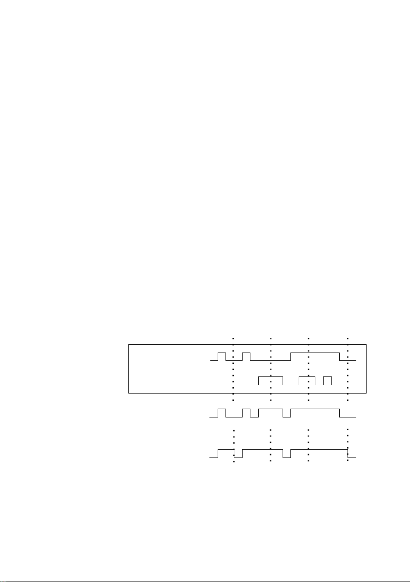
Functional description 5
Single message M1
Single message M2
Centralized message
group marked no acceptance required
(= group message)
Centralized message
group marked acceptance required
Group
Acceptance Acceptance Acceptance
Acceptance
The centralized message of a group characterised Acceptance required links
the states of the single messages contained in that group with an
acceptance signal. The acceptance can either be implemented via an
assigned digital input or via a corresponding menu item, i.e. via the operator
panel. An acceptance accepts all groups at once, no matter via which source
it has been generated.
The centralized message of a group marked Acceptance required is pending
if at least one single message of the group is pending. However, it will only
end with the ending of the last single message if all pending messages have
been accepted. A currently pending single message is also considered
accepted if it had been accepted before it ended.
The fact that a centralized message is still pending after the last single
message has ended indicates that at least one of the single messages has
begun again after the last message has been accepted. In such a case the
single message is or the single messages are to be accepted.
The following illustration shows how the centralized message of a group
marked No acceptance required differs from the one of a group marked
Acceptance required.
These groups with their centralized and group messages are intended to
provide an overview of the plant conditions.
gas-lab Q1 Page 65
Page 74

5 Functional description
This is why the output of these message types is supported in different ways:
In contrast to single messages, centralized and group messages can be
output via digital outputs.
The events Group message begins / Group message ends / Any message
of the group begins / Any message of the group ends can be routed to the
DSfG bus with an attention telegram. It can be determined for each group
upon which events such attention telegrams shall be generated and of
which type they shall be (Alarm, Hint or Warning).
The status of centralized, group and held group messages can be enquired
via DSfG.
Only the centralized message of the messages linked within a group is
entered in the message processing error listing and logbook to keep them
well structured.
A Maintenance switch (M-switch) is used to suppress group and/or centralized
messages if maintenance work has to be carried out.
The setting of this M-switch affects each group differently:
- No influence
A set M-switch does not have any effect on the signalling reactions of
this group.
- Suppression “towards telecontrol”
This means that, if the M-switch is set, the group does no longer
trigger any DSfG attention telegrams and the Held group message is
considered not pending.
- Suppression of all signalling reactions without exception
In this case all messages generated by a group are suppressed if the
M-switch is set.
This means that the group neither generates held group nor group nor
centralized messages. Nevertheless, the centralized message is still
entered in the logbook and error listing.
If the M-switch is set, the main signaller no longer takes the group into
account.
Page 66 gas-lab Q1
Page 75

Functional description 5
Group
Single message M1
Single message M2
Acceptance Acceptance
Main signaller message
The M-switch is activated via an assigned digital input. It cannot be set via the
operator panel for safety reasons.
Status and signalling reactions of single messages remain unaffected by the Mswitch. Single messages are suppressed via the disabling mechanism explained
above.
In addition to the above-mentioned messages a message named Main signaller
is also available. It usually triggers a hooter if being routed to an output. An
additional acceptance input is assigned to the main signaller.
The main signaller may include any number of groups.
It starts operating when a message arrives that belongs to one of the involved
groups, and it ends upon acceptance, no matter whether or not messages are
still pending. The acceptance can be implemented via the digital input assigned
to the main signaller. Besides, if all groups are accepted via the operator panel,
the main signaller is also accepted. It starts operating again when the next
involved message arrives.
The following illustration shows the behaviour of the main signaller in connection
with the acceptance (in case of one involved group):
gas-lab Q1 Page 67
Page 76

5 Functional description
5.3.1.4 Logging on measurement or counter archives
The Q1 is able to run archives for process values, i.e. archives for
measurements and count values. Up to four archive groups with up to 8
channels each are available. It can be determined for each archive group in
which conditions the contained archive channels shall be logged.
The standard procedure used is cyclic data logging (with configurable data
logging cycles of one second up to one hour).
Additionally or alternatively, the data logging can be made conditional upon
certain events occurring during the monitoring of the process values:
It is possible to link the data logging with one or more group(s) of single
messages. In this case the logging takes place upon the beginning and end
of each message contained in one of the involved groups.
If the development of a particular process value shall be logged in detail, a
maximum change rate can be defined for an archive channel. Then the
entire archive group is logged each time the difference between the current
measurement and the value measured during the last data logging exceeds
the maximum change rate. This way, the data is logged more often in case
of quickly changing values.
This option is also available for counter archives, which means you can
specify that the data logging shall always start when a count value has
increased by a defined difference.
Page 68 gas-lab Q1
Page 77

Functional description 5
In addition, measurements and count values are always logged if the input value
has been identified as being disturbed.
It is possible to “freeze” process value archives ". If an assigned message
begins, the corresponding archive continues to log data and stops after a certain
number of entries have been reached. The point of time of the last entry will be
marked with hint PVA <no.> freeze begins (PVA stands for
ProcessValueArchive) in the error listing and logbook of the monitoring module.
The data logging will only be continued if the assigned message ends.
Simultaneously, hint PVA <no.> frozen also ends.
The freezing of measurement archives is useful if you are interested in how a
measurement develops in case a certain event occurs. It may be possible, for
instance, to link the freezing with a centralized message. Then, the freezing will
be activated upon the first beginning of any message of the group. Normal data
logging will not be continued after the end of the last message until the group
has been accepted explicitly, for the centralized message only ends in this case.
gas-lab Q1 Page 69
Page 78

5 Functional description
5
Current time
Error type
(Alarm, Warning or Hint)
DSfG error number
Error type (clear text)
Date and time of Beginning and End (the latter is
only indicated if the error is no longer pending).
„Up“ and „down“ scroll arrows:
There are at least two more
errors in the listing.
5.3.2 Display and operation.
Main display (Monitoring module)
The display indicates the error listing of the gas quality measurement when you
invoke the Monitoring module. The error message with the highest priority level5
is displayed, provided the error listing is not empty.
If the error listing contains further errors, you may scroll through the error listing
via the arrow keys. The little black scroll arrows on the right side of the display
indicate whether or not there is more than one entry in the listing.
The following information is provided for each error:
An alarm has the highest priority level, i.e. it is of greatest importance. A warning has a
higher priority level than a hint.
Cf. Chapter 5.3.1 for an explanation of the terms Alarm, Warning and Hint.
Page 70 gas-lab Q1
Page 79

Functional description 5
6
6
Subordinate menu items (Monitoring module)
Accept
The Accept menu item only exists for the gas quality measurement error listing.
If this menu item is crossed out, the indicated message cannot be accepted
because it is still pending. If Accept is not crossed out, however, the currently
indicated error message can be accepted and thus removed from the error
listing. After the message has been accepted, the menu is cleared and the next
error will be displayed. Just repeat the procedure if you would like to accept this
error, too: Invoke the menu and confirm Accept.
Accept all (only available for the Monitoring error listing)
The Accept all menu item is only available if you are in the error listing
display of the monitoring module; via this menu item you accept all groups
requiring an acceptance together with the main signaller (hooter).
Accept all is crossed out if there is no need to accept any messages.
Next listing
Via Next listing you may switch to the respective following error listing. There
are two error listings: the Gas quality measurement error listing and the
Monitoring error listing.
The following messages are entered in the error listing of the monitoring
module:
Messages named System messages
have top priority. These messages
are usually not visible in the error listing as they are pending for only one
second.
The next position shows an M-switch message if the maintenance switch
has been activated.
Then, all pending centralized messages of groups 1 to 32 are indicated.
System messages are generated for the events Re-start performed, Supply voltage
failure, New parameterisation, and Parameter changed.
gas-lab Q1 Page 71
Page 80

5 Functional description
Name of the shown measurement. Pressing the Enter key opens up a selection list
containing all measurement names. You may switch to the indication of another
measurement via this list.
Current measured quantity of the
associated measurement, incl. unit.
Blinks if the value is disturbed.
Line before last: Minimum value since last resetting, with time mark.
Last line: Maximum value since last resetting, with time mark.
Pending single messages follow according to their priority level.
In order to keep the error listing clearly understandable only such single
messages are entered in the error listing that have been parameterised
accordingly.
In principle, all single messages of the message processing and the M-switch
message do not require an acceptance. Only centralized messages of groups
requiring an acceptance must be accepted. This means that all single, group
and centralized messages of groups that do not require an acceptance
automatically disappear from the error listing when they stop pending.
Centralized messages of groups requiring an acceptance will only end after they
have been accepted and if none of the single messages of the group is pending
any longer. The messages can be accepted even before the last single
message has ended.
Measurements
The gas-net Q1 evaluation computer may have up to 32 parameterised
measurements for maximum/minimum indication on file. If you invoke the
corresponding display, the first measurement will be presented. You can
switch to the display of another measurement via the name.The display
contains the following information in detail:
If the associated measurement is indicated as being disturbed, the display
keeps showing the last valid value. In this case, however, the value is
blinking.
Page 72 gas-lab Q1
Page 81

Functional description 5
Name of the indicated group
Initial message, i.e. the message of
the group that has begun first.
The text is blinking if the message
has not been accepted via the
group yet.
New message, i.e. the message of the group
that was the last one to begin. The text is
blinking if the message has not been
accepted via the group yet.
The measurement display contains the following subordinate menu items:
Resetting
The Resetting menu item sets the minimum and maximum values of
the measurement to the current measurement.
Reset all
The Reset all menu item resets all filed measurements.
Groups
The Groups menu refers to the message processing of the monitoring
module. You may invoke the associated display only if message groups
have been created. The display facilitates an overview of the event status of
the messages linked in a group. If you invoke the associated display, you will
see information on the first group. For switching to the display of another
group you have to get into the edit mode (by pressing the Enter key) and
select the name of the group you want to view from the appearing list.
Confirm your choice by pressing the Enter key again.
If the centralized message of the invoked group is currently pending, the
single message of the group that has begun first is indicated below Initial
message.
gas-lab Q1 Page 73
Page 82

5 Functional description
Name of the selected group
Currently indicated single message of the group. A list with
all messages existing in this group opens up if you press
the Enter key. You may also switch to the indication of
another single message of the group via this selection list.
As this is always the message that has initially caused the beginning of the
centralized message, this information helps to analyse the error status. The
message text is blinking if no message has been accepted yet after the
beginning of the centralized message.
Below the New message menu item you can read off the most recent single
message of the group that has begun. As long as the centralized message
itself is pending the New message indication is updated upon each
beginning of a new message of the group. A New message, too, does not
stop blinking on the display before a message has been accepted after the
beginning of the new message.
Only if neither initial nor new message are indicated, a centralized message
is not pending.
Activate the View submenu to check the status of all single messages
contained in the group:
View
This display provides information on the single messages contained in
the group invoked before. Besides, it provides information on the status
of each contained single message. Due to the mass of information
there is always only one single message indicated on the display at a
time.
As the Name selection list contains all single messages of the
corresponding group you can switch to the indication of any other
single message of the currently selected group.
Page 74 gas-lab Q1
Page 83

Functional description 5
Seconds counter for
minimum pending time
The following information is indicated for each individual message:
Name
Each message is identified via its parameterised name. You may
change to the indication of any other single message of the group via
the Name selection list.
Type
A single message can be derived from a Message, the monitoring of
an Upper or Lower limit value or Gradient monitoring.
Status
The status of a single message is characterised by several
specifications:
On or Off indicates whether the message is pending. Here, a possibly
parameterised minimum pending time is taken into consideration:
Even though the status to be signalled is currently pending, the
associated single message will only be set if the status is pending
longer than the minimum pending time.
To be able to make out whether a single message would be pending
if no minimum pending time would have been assigned to it, the
display includes a seconds counter.
gas-lab Q1 Page 75
If the seconds counter starts counting backwards, the status to be
signalled has already been pending. A minimum pending time is
assigned to each single message. This is why the message itself is
only generated if its status is still pending after the minimum pending
time has elapsed. Therefore, the counter constantly shows how many
seconds of the minimum pending time are remaining. Only after the
counter has reached 0, the status indication of the message will
change from Off to On.
Page 84

5 Functional description
If the status to be signalled ends before the minimum pending time
has elapsed, the counter will be set to 0 but the message will not
begin.
The counter always shows 0 if a minimum pending time has not been
assigned to a single message. In this case the message begins
immediately after the status to be signalled has been detected.
However, it depends on its state (disabled / enabled) whether a single
message is being routed at all: If a single message has been
disabled, the entire subsequent message processing considers it as
not pending.
Tip: The main advantage of the Groups – View menu described here
is the possibility to analyse the status of a group and the single
messages contained therein. This menu only provides information but
does not allow to change the properties of a single message, for
instance to set a disabling mark. For this purpose the Single
messages menu must be invoked. The display of this menu is
structured similar to the one described above.
Single messages
The Single messages menu refers to the message processing of the
monitoring module. It does not only serve to indicate basic information
relating to single messages but also provides the possibility to disable such
messages via the operator panel of the device and to change limit values for
single messages of the measurement monitoring.
In order to switch to the display of another single message you have to get
into the edit mode (by pressing the Enter key) and select the name of the
message you want to view from the appearing list. Confirm your choice by
pressing the Enter key again.
The Single messages display is basically identical with the display of the
Groups – View menu described above.
The parameterised limit value is indicated as additional information in case
of a message derived from measurement monitoring.
Page 76 gas-lab Q1
Page 85

Functional description 5
Pressing the Enter key opens
the selection list containing all
currently blocked messages.
Limit, here: upper limit value.
Note: An additional hysteresis may have been adjusted via PC and with the
parameterisation program to avoid fluttering messages
Limit
The Limit menu item indicates the currently set limit value of the limit
monitoring or the maximum permissible change of the measurement
within a parameterised monitoring period when monitoring gradients.
This dialog allows disabling single messages via the operator panel. It is
also possible the change the limit value to be monitored in case of
measurement monitoring messages. However, the numerical locks must
have been opened for such actions to be carried out.
Disabled messages
The Disabled messages menu refers to the message processing of the
monitoring module. The corresponding display lists all currently disabled
single messages. Additional information indicated on the display comprises
the type of the message, the real message status before the disabling, and
possibly the counter for a monitored minimum pending time.
The Disabled messages menu described here merely provides information.
Please switch to the Single messages menu (see above) if you want to
change the status of a single message (disabled / enabled).
gas-lab Q1 Page 77
Page 86

5 Functional description
This is the last subordinate menu of the Monitoring module:
Switches (Change of switch outputs)
The task of the Switch menu is to display the status of the Switches.
A switch is a message with a preset status (on or off), which can be changed
manually, i.e. via the operator panel of the device. Switch-type messages are
routed to digital outputs (cf. Chapter 5.4.1) to trigger switching operations of any
kind from the gas-net device.
Three switches are available (Switch 1 to Switch 3). To change the status of a
switch you need to invoke the Switches menu, which indicates the current status
of each switch. Select the switch the status of which you would like to change
and change into the edit mode. Afterwards, you may select the other switching
status and confirm via OK. Changing a switch status is subject to the user lock.
Note: Message outputs may be parameterised in such a way that they invert the
output signal during operation. Please consider that this setting also applies to
the output of switches.
Note: The Switches menu offers with Revision 1 and Revision 2 two additional
switching options. However, the gas-net Q1 does not use these options.
5.4 System module
5.4.1 Functions
The System module comprises all basic functionalities of the gas-net device.
Inputs
One such basic functionality of the System module is the processing of the input
information and the transmission of this information to other modules. The
availability of input channels depends on the process board equipment of each
individual device. A Q1 always contains at least one LMFA7 board for the
connection of the sensor system. Besides that, there are further process boards
providing input channels (see Chapter 7.2.2).
The System module’s display offers a special menu for viewing the source,
source value and final value of the input signal on the device display (see
Chapter 5.4.2).
Page 78 gas-lab Q1
Page 87

Functional description 5
Outputs
The evaluation computer always contains one LMFA7 board.
One LMFA7 output board offers 3 transistor outputs for the output of messages.
Furthermore, it contains 4 current outputs for the output of measurements.
In addition to that, there are further gas-net process boards providing output
channels (see Chapter 7.2.2).
The gas-net evaluation computer provides a special menu for viewing and
checking outputs (see Chapter 5.4.2). Checking outputs is only possible if the
locks are open.
DSfG (optional feature for the European market)
DSfG is a digital interface especially developed for data communications
between gas meters (such as gas-net devices).
If you need further information, please contact your local agent.
Please see www.elster.com
gas-lab Q1 Page 79
Page 88

5 Functional description
7
7
Locks
The parameter list of the Q1 contains various parameters that are not subject to
the calibration lock but protected against wilful changes by an operational safety
mechanism. This protection mechanism is called user or numerical lock. Each of
the two contract parties may define a lock of up to 6 digits. These locks are
opened and closed via the keypad (see Chapter 5.4.2). The device
parameterisation defines the locks that shall be valid.
Setting the clock
A free setting of the device internal clock is only possible if the calibration switch
is open. If the latter is closed, you may only reset the clock within a range of
± 20 seconds (and only once within 24 hours). This restriction applies to all time
sources, especially to the manual clock setting via the device’s operator panel.
If you were successful in resetting the time outside the ± 20 seconds-range, two
warnings will be generated. Unsuccessful adjustments result in Clock-synch
failed warnings.
DCF-77 (optional feature for the European market)
Optional the gas-net Q1 can have a DCF77 interface for connecting a radio ¬
clock that receives the PTB time normal about DCF-77 radio signal.
If you need further information, please contact your local agent.
Please see www.elster.com
According to the DSfG Specification:
W811: Clock set new
W820: Clock set old
W812: Clock-synch failed
Page 80 gas-lab Q1
Page 89

Functional description 5
5.4.2 Display and operation.
Main display (System module)
The main display of the System module shows basic device information.
The following details are indicated:
device name with software variant
product version of the device software
serial number of the relevant device
check sum for software authentication (will be calculated after the display
has been invoked)
number of operating hours of the device
Subordinate menu items (System module)
Inputs
The Inputs display enables you to view detailed information of individual
analogue input channels (name, board/channel, input value, etc.).
After you have activated the Inputs menu item, the first channel of the input
board will always be indicated at board location 1. For instance, the display of
the first channel of an EXMFE4 board looks as follows:
To switch to the display of another channel change to the edit mode (by
pressing the Enter key) and select the name of the desired input value from the
appearing list. After you have confirmed your choice by pressing the Enter key,
the display of the selected board will be invoked.
gas-lab Q1 Page 81
Page 90

5 Functional description
Name
Name of the output channel. Serves to identify the
channel and is defined by the device parameterisation.
Board
Board location, board type, version number of the board
software.
Channel
Channel number with operating mode.
Phys. value
The final value of the respective physical variable with
physical unit.
Output value
In case of analogue values: value for the current output (in
mA) calculated on the basis of the final value.
In case of messages: output contact closed / open.
In case of pulse outputs: frequency in Hz, number of pulses
pending in the pulse buffer.
Test value
Only for output testing (see below).
Outputs
The system menu Outputs enables you, similar to the input channels’ display, to
view the assignment and current status of the output channels.
After you have activated the corresponding menu item, details of the first
defined output channel will be presented:
To change to the display of another channel, activate the edit mode (by pressing
the Enter key). A list with the names of all parameterised output channels
appears. After you have chosen the desired output channel and have pressed
the Enter key, the display of the selected channel will be invoked.
Page 82 gas-lab Q1
Page 91

Functional description 5
Output testing
In addition to just viewing the current process values you may also check
the output channels. This means that you can output any current value
between 0 and 20 mA via an analogue output for testing purposes. A
message output can be set to Contact closed or open, and you may also
output pulses for testing reasons. However, only one output can be
switched into the test mode at the same time.
Proceed as described below:
1) Select the desired output channel, and press the Menu key
afterwards.
2) Select the Test on submenu.
The Test value line is selected automatically. Press the Enter key to
switch to the edit mode. If you enter a new value now and confirm it
by pressing the Enter key, this value will be output via the selected
output.
In the activated test mode the Test value indicated in the last line is
no longer crossed out. The Output value menu item also indicates
the output test value.
3) To quit the test mode, press the Menu key again and confirm the
Test off menu item.
Note: You may also quit the test mode by quitting the current display, for
instance via Back or by selecting a different channel.
gas-lab Q1 Page 83
Page 92

5 Functional description
DSfG (optional feature for the European market)
DSfG is a digital interface especially developed for data communications
between gas meters (such as gas-net devices).
Sub menu DSfG
Operaitng mode menü
Among the „own participants” bus addresses (EADRs) lists the Q1 internal
instances..
Menu known participants
Menu line: Bus activityät:
The Q1 can get an attention-Telegram .
If you need further information, please contact your local agent.
Please see www.elster.com
Page 84 gas-lab Q1
Page 93

Functional description 5
DCF77 (optional feature for the European market)
Optional the gas-net Q1 can have a DCF77 interface for connecting a radio ¬
clock that receives the PTB time normal about DCF-77 radio signal.
If you need further information, please contact your local agent.
Please see www.elster.com
Locks.
After you have activated the Locks menu item, a display is invoked indicating
the current status of the user locks. The display is empty if no lock has been
defined. New lock digits must always be defined by parameterisation.
The submenu contains the following items:
Open
This menu item is crossed out if all locks are open. If at least one lock
is closed, you may activate the Open menu item by pressing the
Enter key. A dialog will be invoked in which you may enter the
numerical lock(s):
If only one lock has been defined, only one line will be shown here.
Select the lock you would like to open in the first step. Change to the
edit mode via the Enter key as usual and enter the lock’s string of
digits.
Confirm the code by pressing the Enter key. If the entered string of
digits is incorrect, it is not possible to quit the edit mode via the Enter
key. You have to correct the code first (or quit the menu via the
rightward arrow key).
It is also possible to change the status of just one lock. Press the
Menu key after you have successfully entered the numerical lock(s).
Open the locks with OK or leave them closed by confirming Cancel.
gas-lab Q1 Page 85
Page 94

5 Functional description
8
Close
All defined locks are closed.
This menu item appears being crossed out and is thus not selectable
if all locks are closed. If the calibration switch is open, all locks are
automatically open, too, and cannot be closed.
Set clock
Activate this menu item to adjust the internal device time.
You may re-enter time and date step by step via the numerical keypad in the
edit mode, i.e. after you have pressed the Enter key.
The time zone menu item offers a selection list (summer/winter time) for you to
choose the seasonal time zone as soon as you are in the edit mode.
However, it is also possible to operate the device throughout the year without a
seasonal time change. The seasonal time change can be prevented by
parameterisation. In such a case, the phrase not used appears next to Time
zone, and it is not possible to change to the edit mode here.
After having set the time correctly, invoke the menu. Return to the main display
without accepting the new time adjustment via Cancel. You may only confirm
your setting via OK if the acceptance of the new time is permissible8.
Display test
You may check whether or not the display and status LED function correctly by
performing the display test. After you have activated the Display test menu item,
the pixels of the display are alternately switched on and off. At the same time
the status LED shows all three colours after each other. Finish the display test
via Back.
If the calibration switch is closed, resetting the clock is only permissible within a range of
± 20 seconds and only once within 24 hours.
Page 86 gas-lab Q1
Page 95

Functional description 5
5.5 Integrated RDT module
(optional feature for the European market and, not available
with all software variants)
5.5.1 Function
The optional function block has the task of realizing a data connection between
the gas-net device and a remote control center. The center is a couple of him
during an active data connection to be logically equal participant in the data
traffic.
If you need further information, please contact your local agent.
Please see www.elster.com
5.5.2 Display and operation
Main display (Modul Integrated RDT)
The main display of the module Integrated RDT indicates in what state the RDT
is.
Optional feature for the European market and, not available with all software
variants.
If you need further information, please contact your local agent.
Please see www.elster.com
gas-lab Q1 Page 87
Page 96

5 Functional description
Subordinate menu items (modul intregrated RDT)
Optional feature for the European market and, not available with all software
variants.
Historie
Menu RDT-statistics
GSM (only when connected to a wireless modem)
Optional feature for the European market
If you need further information, please contact your local agent.
Please see www.elster.com
Page 88 gas-lab Q1
Page 97

Functional description 5
9
5.6 DSfG module, Data exchange module
(Gateway functionality, not available with all software
variants)
The DSfG protocol is a digital data protocol, especially developed for the
communication between gas meters in gas measuring and regulating stations.
The gas-net Q1 is always equipped with a DSfG interface. All important
measurements and characteristic data are provided as DSfG data elements via
the DSfG protocol according to the specification. These data elements are
addressed via special addresses.
However, gas measuring and regulating stations often also contain a PLC
(programmable controller) the tasks of which are the open- and closed-loop
control of the station and the telecontrol interfacing to a remote control centre.
Most of the PLCs are not DSfG-capable but use other digital communication
protocols9. Consequently, they cannot be simply included in the DSfG station
group. In such cases a protocol interfacing between DSfG and host protocol is
necessary (gateway functionality).
This functionality is only available in Q1 software variants containing the DSfG
and Data exchange modules.
5.6.1 DSfG module (Optional feature for the European market)
The optional module controls the DSfG side of data exchange.
If you need further information, please contact your local agent.
Please see www.elster.com
Typical protocols are, for instance, 3964R/RK512 (e.g. in case of Siemens S5/S7) or
Modbus-RTU (e.g. in case of Cegelec Modicon).
gas-lab Q1 Page 89
Page 98

5 Functional description
5.6.2 Data exchange module
5.6.2.1 Function.
The Data exchange module controls the host side of the gateway functionality.
All data points that are available during operation and shall be forwarded to a
host must be positioned on registers or data blocks/data words for the host. It is
also possible to scale the value in a suitable way before forwarding it, depending
on the data type. Usually, the data to be forwarded is the content of DSfG data
elements that have been polled by the DSfG module via a DSfG query telegram.
The forwarding of the received DSfG data to the host is defined in the Data
exchange module. The data transport in the direction to the host is processed
cyclically. If a new telegram arrives from the DSfG side, the associated export
values will be updated. In addition to the specification of the destination in the
host, the description of the export value also defines the way of positioning the
data point in the host (e.g. size, scaling, limits, and bit position).
A particular import value describes for the reverse data flow direction at which
position in the host a data point shall be collected and in which way it shall be
converted. It can be defined in the parameterisation whether the transmission to
the DSfG side shall be cyclic or event-driven.
Any number of import values from the host can be combined to a job group. All
data points of a job group are always put into the transfer memory together and
simultaneously. However, only after all of them have been collected again once
more. Moreover, a job group may be linked with a trigger. A trigger is a defined
position in the host and initiates a new processing of a job when its content has
changed.
Page 90 gas-lab Q1
Page 99

Functional description 5
5.6.2.2 Protocol-specific facts: RK512 / 3964R
The gateway functionality of the gas-net Q1 supports the protocol consisting of
3964R (data link layer) and RK512 (data presentation).
Look up the settings of the protocol parameters in exactly this form in the
manuals of the programmable controller and adjust them in the communications
processor procedure.
The implementation of the RK512 protocol in the gas-net device is restricted to
the data transmission between data blocks. The smallest information unit is a
data word. Such a data word has a length of 16 bits and may contain, for
instance, several messages, a status overview in the form of a bit string, or a
binary measurement.
The structure of the management of these data words is rather simple; there are
up to 256 larger units, called data blocks, each of which may contain up to 256
data words. Data blocks and data words are numbered consecutively from 0 to
255, with the numbers serving as addresses.
A single data word is clearly defined by exactly three details:
the address of the data block (0..255)
the address of the data word (0..255)
the content of the data word
The addresses to be assigned to the host data in the gas-net parameterisation
therefore consist of a data block/data word (DB/DW) pair. Data block 0 is usually
used for intrasystem host variables. This is why you should use data block 0
neither for exporting values towards the host nor for importing host values.
In special cases it may happen that the host only masters the subordinate
3964R protocol layer. This means that the following restriction applies: As no
DB/DW information is transmitted on the 3964R protocol level, all data to be
exported or imported must be arranged as a string. The number of dates is thus
limited to 64 data words per transmission. This is why in the GW-GNET+
interface (Data exchange module) the positions for import and export values are
not indicated in the DB/DW form but as serial register numbers.
gas-lab Q1 Page 91
Page 100

5 Functional description
Communication protocol:
RK512/3964R – point-to-point
Interface:
V24 (RS232) with PC/AT pin assignment at the gas-net
device (COM2-interface).
RS232 or RS422 via serial interface of an MSER2-board in
the gas-net device.
Transmission rate:
adjustable to 2400, 9600, 19200 or 38400 baud
Transmission parameters:
8 data bits, even parity, 1 stop bit
3964R telegrams:
Max. 128 bytes (64 DW) per telegram
RK512 response
telegrams:
A maximum of 64 data words per telegram, no 3964R
response telegrams. In the RK512 slave operating mode
(i.e. host = master), the gas-net device generates the
response telegrams listed in the table below:
The necessary programming of the host can be minimised by selecting the
Master operating mode for the gas-net Q1. In this case it is not necessary to
compile a job list for the host. The entire data block assignment is carried out via
the gas-net device parameterisation. However, at least the agreed data blocks
and the basic protocol functionality must have been created in the host of
course.
The communication between the host computer and the gas-net Q1 is subject to
several basic requirements. The following list provides a summary:
Page 92 gas-lab Q1
 Loading...