


EnCal 3000
Gas Chromatograph
Hardware Manual
73022344 LC 05.10.2016
___________________________________________________________________________________________________________
EnCal 3000 – Hardware Manual 05/10/2016

Elster GmbH
Contact Information ...................................................................................................................................... 3
Safety Information ........................................................................................................................................ 4
Gas quality measurement system EnCal 3000 ............................................................................................. 6
1
Process Gas Chromatography – General Introduction ................................................................... 7
1.1 Analytical Principle ................................................................................................................................ 7
1.1.1 Column ................................................................................................................................. 8
1.1.2 Detector ................................................................................................................................ 9
1.1.3 Sample Injector ................................................................................................................... 10
1.2 Process Gas Chromatography .............................................................................................................. 11
2
Functional Design ................................................................................................................................ 12
2.1 Introduction ....................................................................................................................................... 12
2.2 Enclosure ........................................................................................................................................... 13
2.3 Assembly of major components and internal components ....................................................................... 14
2.4 Channel ............................................................................................................................................. 15
2.5 Processor Board ................................................................................................................................. 19
2.6 Interconnection Board ......................................................................................................................... 21
2.7 Cabinet Heaters .................................................................................................................................. 22
2.8 Internal sample system ....................................................................................................................... 23
2.8.1 Double Block and Bleed Function ........................................................................................... 25
2.8.2 Internal Sample Bypass ........................................................................................................ 25
2.9 Gas Connections ................................................................................................................................. 26
2.10 Breather ............................................................................................................................................ 27
2.11 Cable entries ...................................................................................................................................... 28
2.12 External Switch .................................................................................................................................. 29
2.13 Configuration with two Carrier Gases .................................................................................................... 30
3
Technical Specifications ..................................................................................................................... 31
4
Data Communication ........................................................................................................................... 34
4.1 Local TCP/IP Data Communication ....................................................................................................... 34
4.2 Local Serial ModBus Data Communication ............................................................................................. 35
4.3 Remote Access ................................................................................................................................... 36
4.4 ModBus Communication ...................................................................................................................... 37
5
Hardware Installation ......................................................................................................................... 38
5.1 Installation specifications ..................................................................................................................... 38
5.1.1 Weight and Dimensions ........................................................................................................ 38
5.1.2 Installation clearance ............................................................................................................ 38
5.1.3 Wall mounting ..................................................................................................................... 39
5.1.4 Connection of utilities ........................................................................................................... 40
5.1.5 Connections to the EnCal 3000 Interconnection board ............................................................. 41
5.2 Hardware Start-up .............................................................................................................................. 44
APPENDIX 1: Possible hardware options of the EnCal 3000 ............................................................... 46
APPENDIX 2: DECLARATION OF CONFORMITY ENCAL 3000 .............................................................. 53
APPENDIX 3: CERTIFICATE EC-Type Examination ................................................................................ 57
___________________________________________________________________________________________________________
EnCal 3000 - Hardware Manual 05/10/2016
2/61

Contact Information
Manufacturer:
Aftersales/ Service Germany & International:
Aftersales /Service International:
Or your local agent:
Elster GmbH
Steinern Straße 19-21
55252 Mainz-Kastel
Deutschland / Germany
Tel. ++49 (0) 61 34 / 605-0
www.elster.com
Elster GmbH
Schlossstrasse 95a
44357 Dortmund
Deutschland / Germany
Tel. ++49 (0) 231 93 71 10-88
e-mail: system.Support-DO@elster.com
Elster-Instromet N.V.
Rijkmakerlaan 9
2910 Essen
Belgien / Belgium
Tel. ++32 (0) 3 6 700 700
e-mail: aftersales@elster-instromet.com
www.elster-instromet.com
Elster GmbH
___________________________________________________________________________________________________________
EnCal 3000 - Hardware Manual 05/10/2016
3/61

Safety Information
Electrical Safety
The EnCal 3000 is a gas analyser designed to be installed in hazardous areas. For this purpose it is certified
according to:
ATEX II 2 G
IECEx
Class I, Division 1, Groups B, C, D T6
Class I, Zone 1, AEx db IIC T6
In compliance with:
IECEx:
IEC 60079-0 : 2011
IEC 60079-1 : 2014
ATEX:
EN 60079-0 : 2012
EN 60079-1 : 2014
FM standards
Class 3600 : 2011
Class 3615 : 2006
Class 3810 : 2005
ANSI:
ANSI/ISA 60079-0 : 2013
ANSI/UL 60079-1 : 2015
Detailed information on this certificate can be found in APPENDIX
Ex-d IIC T6 Gb
Ex-d IIC T6 Gb
Elster GmbH
___________________________________________________________________________________________________________
EnCal 3000 - Hardware Manual 05/10/2016
4/61

Elster GmbH
The operation and maintenance of such equipment should only be performed by qualified personnel.
Fuse replacement must only be performed by Elster GmbH authorized personnel.
The following basic rules must be observed in all circumstances:
The flameproof enclosure may not be opened when an explosive gas atmosphere may be pre-
sent. The process pressure shall be limited to 2 MPa to ensure that the pressure rise inside the
flameproof enclosure remains below 10 kPa. The functional pressure must be lower see chapter 3
and section 5.1.4 containing the specifications. Before any start-up, verify all connections of the
unit for tight sealing.
For information on the dimensions of the flameproof joints the manufacturer shall be contacted.
WARNING! ELECTROSTATIC HAZARD!
Because of the potential electrostatic charging of the paint layer, the housing should only be
cleaned by using a moist cloth to prevent charging
CASE MUST BE EARTHED!
Important disclaimer:
If the equipment is used in a manner not specified by the manufacturer, the protection provided
by the equipment may be impaired. Gases which are flammable or explosive under exclusion of
oxygen. (E.g. acetylene C2H2) should not be fed to the measuring device.
Installation instructions mentioned in this manual are intended for information only. The installation of this equipment
must conform to any national, local, or company codes applicable to the location. Elster-Instromet assumes no responsi-
bility for compliance with these requirements. It is suggested that a review of the codes be made prior to installation.
___________________________________________________________________________________________________________
EnCal 3000 - Hardware Manual 05/10/2016
5/61

Elster GmbH
Gas quality measurement system EnCal 3000
The gas quality measurement system EnCal 3000 consists in its basic configuration of a measuring unit and
an optional Encal3000 controller.
The measuring unit is the real gas chromatograph. It performs the analysis by measuring technology auton-
omously.
It is configured with the PC program "RGC 3000". It is possible to install an additional optional Encal3000
controller. The subsystems communicate with each other via Modbus. (see Figure 1)
This manual describes the Hardware of the Encal3000 gas chromatograph (measuring unit). The other sub-
systems are described in separate manuals.
Basic configuration EnCal 3000 (Measuring unit and an optional Encal3000 controller)
Figure 1
___________________________________________________________________________________________________________
EnCal 3000 - Hardware Manual 05/10/2016
6/61
Elster GmbH
1 Process Gas Chromatography – General Introduction
1.1
Analytical Principle
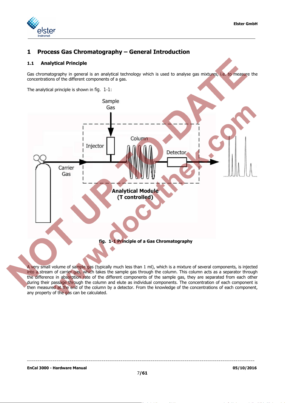
Gas chromatography in general is an analytical technology which is used to analyse gas mixtures, i.e. to measure the
concentrations of the different components of a gas.
The analytical principle is shown in
fig. 1-1
:
fig. 1-1 Principle of a Gas Chromatography
A very small volume of sample gas (typically much less than 1 ml), which is a mixture of several components, is injected
into a stream of carrier gas, which takes the sample gas through the column. This column acts as a separator through
the difference in absorption rate of the different components of the sample gas, they are separated from each other
during their passage through the column and elute as individual components. The concentration of each component is
then measured at the end of the column by a detector. From the knowledge of the concentrations of each component,
any property of the gas can be calculated.
___________________________________________________________________________________________________________
EnCal 3000 - Hardware Manual 05/10/2016
7/61

Elster GmbH
1.1.1 Column
A GC column is a relatively long spiral of tubing with very small internal diameter. Typical dimensions of the used col-
umns in the Encal3000 have a length of several meters and internal diameters of <0.1 mm. They are made of inert ma-
terials like fused silica and stainless steel. Every GC column has a so-called stationary phase inside, which acts as an
absorption layer for the gas molecules flowing through the column.
fig. 1-2 Different types of gas chromatographic columns
Various configurations exist:
Wall coated open tubular column: the stationary phase is a thin liquid layer coated on the inner wall of
the column (for example type 5CB)
Packed column: the stationary phase is coated on a packing, which is equally distributed throughout
the column (for example type HSA)
Support coated open tubular column: the stationary phase is a coated packing, which itself is coated
on the inner wall of the column (for example type M5S mole sieve)
Porous layer open tubular column: the stationary phase is a porous layer on the inner wall of the col-
umn (for example type PPU)
___________________________________________________________________________________________________________
EnCal 3000 - Hardware Manual 05/10/2016
8/61

Elster GmbH
1.1.2 Detector
In the natural gas industry, the most popular detector is the TCD: Thermal Conductivity Detector. It’s a relatively simple,
very efficient and very robust detector.
Another reason for the popularity of the TCD in the natural gas industry is the fact that gas chromatographs are used
mainly for the measurement of gas properties like heating value, Relative density and Wobbe index. The calculation of
these parameters is based on the concentrations of the main gas components.
TCDs newer design in MEMS technology (MEMS = Micro-Electro-Mechanical System), which are also used in the Encal
3000 are much smaller in terms of volume. The components can be integrated at the same time much more accurately,
so that the analytical precision is for example 1 ppm for n-pentane.
Traditionally the two TCD’s (reference + measurement detector) are integrated in a so-called Wheatstone configuration,
which increases significantly the signal-to-noise ration of the measurement.
fig. 1-3 Typical electrical TCD circuit
___________________________________________________________________________________________________________
EnCal 3000 - Hardware Manual 05/10/2016
9/61
Elster GmbH
1.1.3 Sample Injector
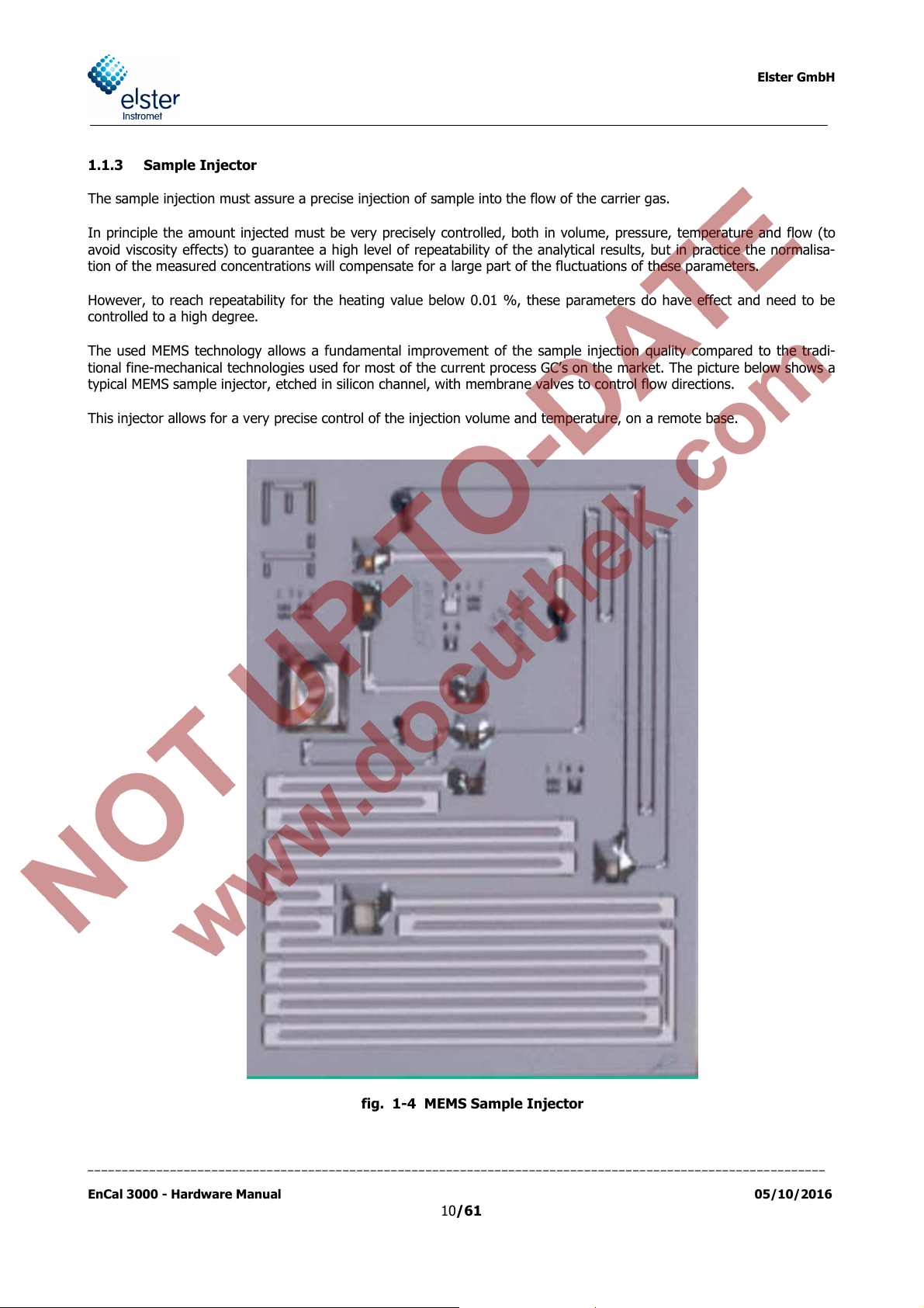
The sample injection must assure a precise injection of sample into the flow of the carrier gas.
In principle the amount injected must be very precisely controlled, both in volume, pressure, temperature and flow (to
avoid viscosity effects) to guarantee a high level of repeatability of the analytical results, but in practice the normalisa-
tion of the measured concentrations will compensate for a large part of the fluctuations of these parameters.
However, to reach repeatability for the heating value below 0.01 %, these parameters do have effect and need to be
controlled to a high degree.
The used MEMS technology allows a fundamental improvement of the sample injection quality compared to the tradi-
tional fine-mechanical technologies used for most of the current process GC’s on the market. The picture below shows a
typical MEMS sample injector, etched in silicon channel, with membrane valves to control flow directions.
This injector allows for a very precise control of the injection volume and temperature, on a remote base.
fig. 1-4 MEMS Sample Injector
___________________________________________________________________________________________________________
EnCal 3000 - Hardware Manual 05/10/2016
10/61

Elster GmbH
1.2 Process Gas Chromatography
The Encal 3000 Process Gas Chromatograph (PGC) transfers the core laboratory technique to process conditions. Apart
from the analytical performance specifications, a PGC therefore needs to be designed to match the following specifica-
tions:
Explosion safety.
Extreme environmental conditions:
o High and low temperatures
o Dust and precipitation
o Electro-magnetic influence
o Wind
o Corrosive atmospheres
o Vibrations and shocks
Complete stand-alone operation, no operator interference during normal operation:
o Automatic and continuous analysis of different streams
o Control and processing of analytical measurement executed internally, no peripheral device needed
o Automatic calibration and verification
Standard maintenance limited to yearly intervals, without need for specifically trained people
o High reliability of the components
o High degree of protection to any contaminant (liquids, vapour or particles) in the sample gas
Analytical results available in industrial formats (for natural gas industry serial ModBus or ModBus TCP/IP)
Internal data storage of all data, including averages, calibration data, events and alarms, during the last 35
days, to permit the operator to retrieve data in the past in case the continuous analysis was interrupted for any
reason.
The EnCal 3000 is designed to meet or exceed all of the above requirements. At the same time the unit uses analytical
technology which can compete with the highest standards used in the laboratory world, surpassing any PGC currently
used in the natural gas industry.
___________________________________________________________________________________________________________
EnCal 3000 - Hardware Manual 05/10/2016
11/61
Elster GmbH
2 Functional Design
2.1 Introduction
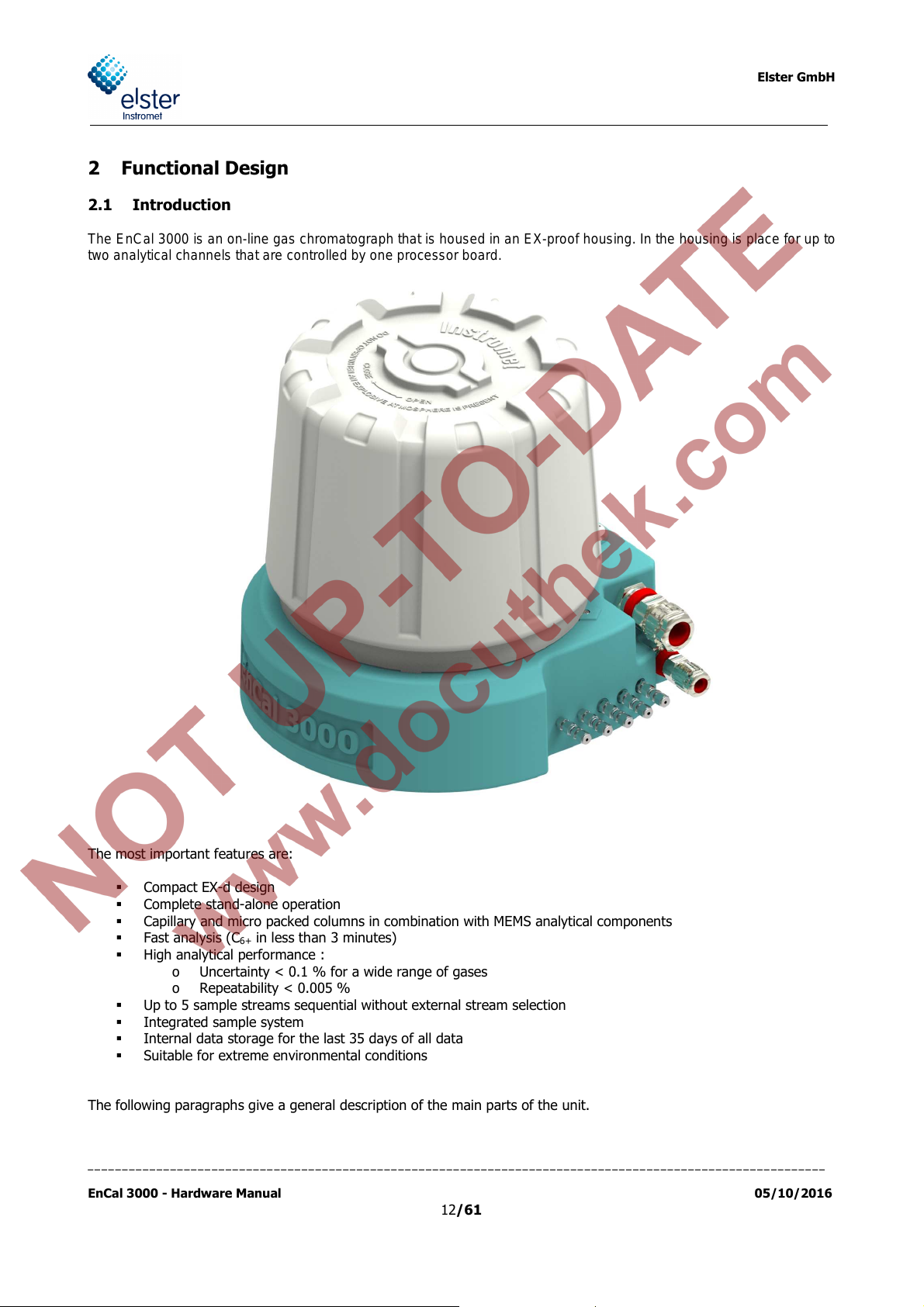
The EnCal 3000 is an on-line gas chromatograph that is housed in an EX-proof housing. In the housing is place for up to
two analytical channels that are controlled by one processor board.
The most important features are:
Compact EX-d design
Complete stand-alone operation
Capillary and micro packed columns in combination with MEMS analytical components
Fast analysis (C
in less than 3 minutes)
6+
High analytical performance :
o Uncertainty < 0.1 % for a wide range of gases
o Repeatability < 0.005 %
Up to 5 sample streams sequential without external stream selection
Integrated sample system
Internal data storage for the last 35 days of all data
Suitable for extreme environmental conditions
The following paragraphs give a general description of the main parts of the unit.
___________________________________________________________________________________________________________
EnCal 3000 - Hardware Manual 05/10/2016
12/61
2.2 Enclosure
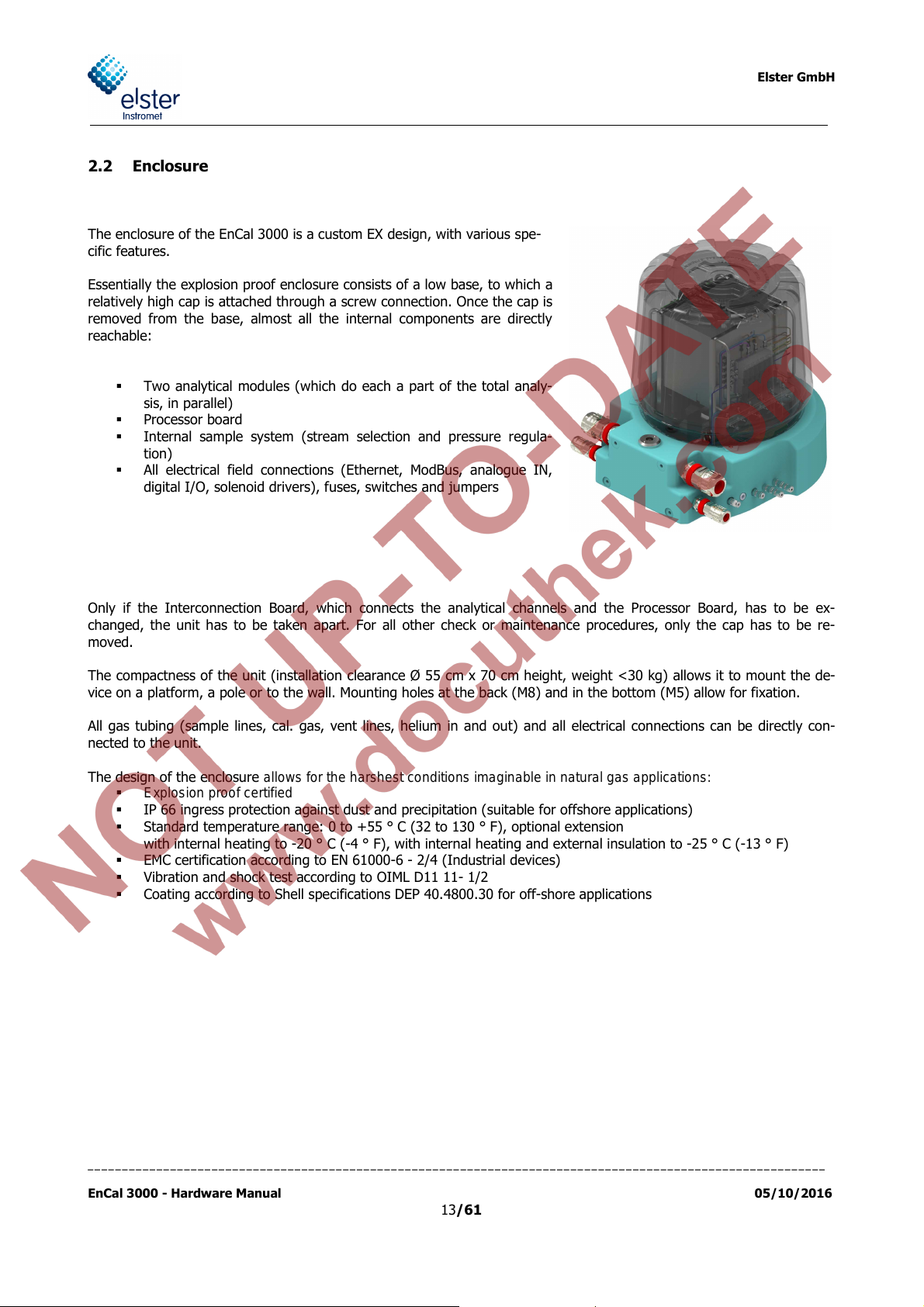
The enclosure of the EnCal 3000 is a custom EX design, with various spe-
cific features.
Essentially the explosion proof enclosure consists of a low base, to which a
relatively high cap is attached through a screw connection. Once the cap is
removed from the base, almost all the internal components are directly
reachable:
Two analytical modules (which do each a part of the total analy-
sis, in parallel)
Processor board
Internal sample system (stream selection and pressure regula-
tion)
All electrical field connections (Ethernet, ModBus, analogue IN,
digital I/O, solenoid drivers), fuses, switches and jumpers
Elster GmbH
Only if the Interconnection Board, which connects the analytical channels and the Processor Board, has to be ex-
changed, the unit has to be taken apart. For all other check or maintenance procedures, only the cap has to be re-
moved.
The compactness of the unit (installation clearance Ø 55 cm x 70 cm height, weight <30 kg) allows it to mount the de-
vice on a platform, a pole or to the wall. Mounting holes at the back (M8) and in the bottom (M5) allow for fixation.
All gas tubing (sample lines, cal. gas, vent lines, helium in and out) and all electrical connections can be directly con-
nected to the unit.
The design of the enclosure allows for the harshest conditions imaginable in natural gas applications:
Explosion proof certified
IP 66 ingress protection against dust and precipitation (suitable for offshore applications)
Standard temperature range: 0 to +55 ° C (32 to 130 ° F), optional extension
with internal heating to -20 ° C (-4 ° F), with internal heating and external insulation to -25 ° C (-13 ° F)
EMC certification according to EN 61000-6 - 2/4 (Industrial devices)
Vibration and shock test according to OIML D11 11- 1/2
Coating according to Shell specifications DEP 40.4800.30 for off-shore applications
___________________________________________________________________________________________________________
EnCal 3000 - Hardware Manual 05/10/2016
13/61

Elster GmbH
2.3 Assembly of major components and internal components
fig. 2-1 shows the exploded view of the different internal components of the Master Unit of the EnCal3000
The frame is used for mounting the components. It allows the removal of all the direct and individual components, with
the exception of the interconnection board. The components can be removed directly and individually by unscrewing just
a few screws.
If the Interconnection Board must be removed (bottom), the frame has to be removed from the enclosure base first. This
arrangement permits the service engineer to easily review the board in case malfunctions would occur.
The detailed description of the functionalities of each component will be done in the following paragraphs.
fig. 2-1 Exploded View on the Internal Parts of the EnCal 3000
___________________________________________________________________________________________________________
EnCal 3000 - Hardware Manual 05/10/2016
14/61

Elster GmbH
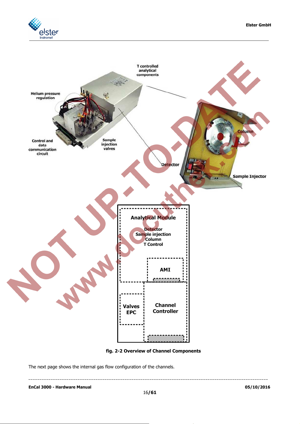
2.4 Channel
A channel consists of the following subcomponents:
Analytical Module: This is the heart of the EnCal 3000: it contains the column, sample injector, detector and the
heaters for the columns and the injector
AMI (Analytical Module Interface): electronic circuit which controls the analytical components of the Analytical
Module. It has its own EDS (Electronic Data Sheets) which stores the local configuration parameters
EPC: Electronic Pressure Control for adjusting the pressure of the analytical column
Channel Controller: electronic circuit which controls the communication between AMI and Processor Board, and
also controls the EPC (Electronic Pressure Control) and valves needed for the control of the internal gas flow
circuit.
Both AMI and Channel Controller have their own EDS (Electronic Data Storage) which stores the local configuration pa-
rameters. This enables to swap to channels without a need for reconfiguration, uploading the internal settings is suffi-
cient to fully install a new channel in an existing unit.
The Analytical Module uses different columns for different applications. In the EnCal 3000 two columns are used:
HSA column (HaySep), for the analysis of N
5CB column 4m or 8m, for the analysis of the higher hydrocarbons (C
, CH4, CO2 and C2H6
2
up to C8H18 or up to C9H20)
3H8
For devices build before 2008 the 5CB-4m channel was used for the analysis up to C6+ and the 5CB-8m channel just for
the analysis up to C9. Since 2008 the 5CB-8m becomes used for both options, the main reason for this change is that
the separation of the peaks especially for n-butane and neo-pentane is better for the 8m long column.
Another possible Channel configuration for the special application biogas is:
M5A column (molesieve), 10m long, for the analysis of H
PPU column, 10m long, for the analysis of the hydrocarbons (CH
, O2 and N2.
2
up to n-C4H10) and CO2
4
Another possible Channel configuration for the analysis of hydrogen and natural gas is:
• COX column, 1m long for the components (He), H2, N2, CH4, CO2 and C2H6
• 5CB column, 8m long for the higher hydrocarbons (C3H8 to C9H20)
In the biogas-application for the M5A column, two additional internal humidity filters are required, which are mounted on
the module. These filters are used to reduce humidity to a minimum. Humidity can penetrate by diffusion of air into the
analytical column.
Without the filter, this humidity would reach the analytical module and be absorbed by the column material. Therefore,
the retention times of the measured components would reduce always so that the separation of the measured compo-
nents is deteriorated and a heating up of the column would be required after about 3 months.
With the filters ensures that a heating up of the M5A column is not necessary within a year (calibration cycle). As the
capacity of the attached filter is very low, the filter should be changed with each recalibration. For the carrier gas argon
always an additional external humidity filter should be used.
___________________________________________________________________________________________________________
EnCal 3000 - Hardware Manual 05/10/2016
15/61
Elster GmbH
fig. 2-2 Overview of Channel Components
The next page shows the internal gas flow configuration of the channels.
___________________________________________________________________________________________________________
EnCal 3000 - Hardware Manual 05/10/2016
16/61

Elster GmbH
fig. 2-3 Internal Gas Flow Circuit for each Analytical Channel of the EnCal 3000,
during Normal Operation (top) and sample Injection (below)
___________________________________________________________________________________________________________
EnCal 3000 - Hardware Manual 05/10/2016
17/61

Elster GmbH
Pre
column
Solenoid V5
inlet
Column vent
Reference vent
Manifold block
Solenoid V1
Solenoid V2
Detector
Reference
column
Analytical
column
Injector
inject valve
sample
loop
sample valve
Sample
Solenoid V6
outlet
EGC/Ref vent
BF vent
Sample vent
Pressure
sensor
Solenoid V4
Pump Manifold
Pump
Pump valve
Solenoid V3
Backflush
valve
Pre
column
Injector
Solenoid V5
inlet
Solenoid V6
outlet
Column vent
Reference vent
Manifold block
Pressure
sensor
Solenoid V1
Solenoid V2
Solenoid V3
Detector
Reference
column
Analytical
column
Backflush
valve
inject valve
sample
sample valve
loop
Sample
EGC/Ref vent
BF vent
Sample vent
Solenoid V4
Pump Manifold
Pump
Pump valve
fig. 2-4 Internal Gas Flow Circuit for each Analytical Channel with backflush of the EnCal 3000,
before activating backflush valve (top) and after activating backflush valve (below)
___________________________________________________________________________________________________________
EnCal 3000 - Hardware Manual 05/10/2016
18/61

Elster GmbH
Proce
s
sor
2.5
Processor Board
The main components of the board are:
Arm9 Processor
A Flash-Memory 32 MB for local data storage
The Ethernet-Port
Data communication ports (COM1-4) for serial Modbus, Analogue and Digital I/O
USB Port
I/O Controller for Communication to the analytical channels
Pressure- and Temperature Sensor
COM2
USB
DHCP
Switch
Ethernet
Port
Arm9
Serial Ports
COM3 + 4
COM1
SD-Card
Analogue
I/O
Digital I/O
I/O Controller
Configuration
Jumper
fig. 2-5: Processor Board connections
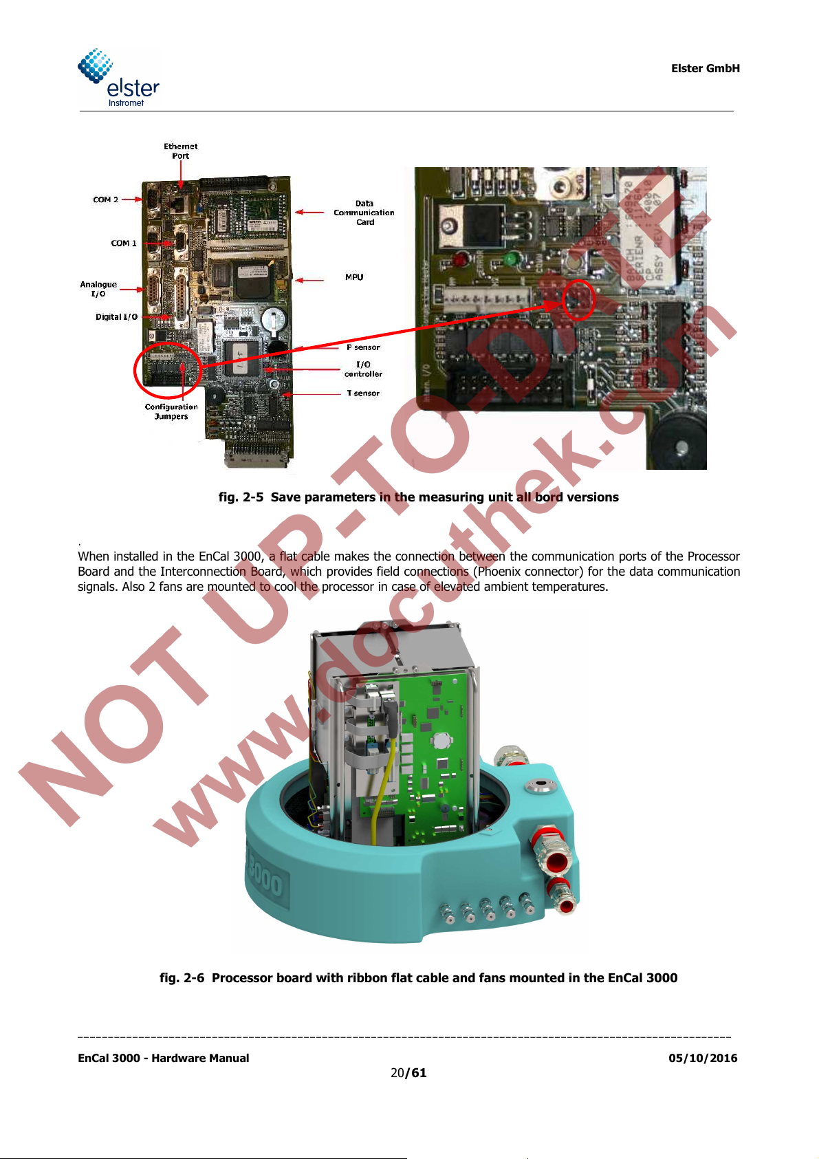
Save parameters in the measuring unit
Setting the "Configuration Jumpers" can protect the parameters on the measuring unit computer witch was loaded by
using the software RGC 3000. This configuration Jumper is at the same position for the old and the new mainboard.
If the jumper is set, the parameters inside the measuring unit cannot be override.
Changes in the parameters can only be transferred to the measuring unit, if the jumper is not set. The setting of the
jumper, can be checked on the display of the “instrument status” page. See Section 3.2 of the software manual. How to
set the jumper is shown in Figure 2.6.
___________________________________________________________________________________________________________
EnCal 3000 - Hardware Manual 05/10/2016
19/61
Elster GmbH
fig. 2-5 Save parameters in the measuring unit all bord versions
.
When installed in the EnCal 3000, a flat cable makes the connection between the communication ports of the Processor
Board and the Interconnection Board, which provides field connections (Phoenix connector) for the data communication
signals. Also 2 fans are mounted to cool the processor in case of elevated ambient temperatures.
fig. 2-6 Processor board with ribbon flat cable and fans mounted in the EnCal 3000
___________________________________________________________________________________________________________
EnCal 3000 - Hardware Manual 05/10/2016
20/61

2.6 Interconnection Board
This board has the following functions:
Power supply input (24 VDC)
DC/DC converter
Connection of Processor Board with Analytical
Modules
Field data communication connectors
Actuation of stream select solenoids
Enclosure temperature regulation
Internal DC/DC conversion for various circuits
Elster GmbH
fig. 2-7 Interconnection Board
The following diagram shows the overall electrical configuration EnCal3000 in a rough overview.
fig. 2-8 Overall Electrical Configuration of the EnCal 3000
___________________________________________________________________________________________________________
EnCal 3000 - Hardware Manual 05/10/2016
21/61

Elster GmbH
2.7 Cabinet Heaters
The cabinet heaters are used for frost protection. They are attached directly to the mounting plates and provide addi-
tional heat when the internal enclosure temperature goes below 10 °C (50 °F). Figure 2.10 shows the location of the
cabinet heaters.
For the regulation of the heaters standard thermostats with a fixed setting are used. These thermostats are connected
to the interconnection board close to the connectors for the power supply of the heaters (see also fig. 5.5, connectors
J12 and J13).
___________________________________________________________________________________________________________
EnCal 3000 - Hardware Manual 05/10/2016
fig. 2-9 Cabinet heaters location in the EnCal 3000
22/61

Stream selection block
2.8 Internal sample system
The internal sample system has the following functions:
Double block and bleed stream selection (up to 5 streams / 1 cal)
Pressure regulator. Advised input pressure is 2 barg. Input pressure range is 1 to 5 barg
Split of the helium and sample gas to the 2 analytical columns
Combination of the vent lines of the 2 modules
Purge of the cabinet with Helium (optional)
Integrated fast loop function (stream purge)
Elster GmbH
Stream purge
Helium purge valve
(optional)
Pressure regulators
fig. 2-10 Front view of the internal sampling/stream selection system
Helium Purging (optional)
Helium enters the manifold and is split to both analytical modules. Through a purge valve the helium can be vented into
the housing, to expel the air in the housing (activated by time relay 3). Additionally to this the column vent is released
into the housing which is nearly pure helium. If there is a leak in the housing no combustible mixture can be formed
because of the absence of air. The housing withstands the pressure of an explosion but by purging the housing with
Helium the chance of internal damage is also reduced significantly. The purge and the small amount of helium that is
vented into the housing also protects the internal components against moisture or other aggressive components entering
the housing through the breather.
___________________________________________________________________________________________________________
EnCal 3000 - Hardware Manual 05/10/2016
23/61

Elster GmbH
fig. 2-11 Flow diagram Sample Conditioning and Selection System
___________________________________________________________________________________________________________
EnCal 3000 - Hardware Manual 05/10/2016
24/61

Elster GmbH
2.8.1 Double Block and Bleed Function
After small particles are filtered out by the inlet filters in the inlet couplings, the pressure is reduced to approximately 0.8
barg. From the pressure regulators the gas will flow to the manifold. There are several valves mounted on the manifold.
The two most right valves are purge valves. The upper purge valve is the sample bypass valve (Activated by
timed relay 2). The lower is a helium purge valve and activated by timed relay 3.
The stream and calibration valves form pairs that are actuated at the same time.
The valves left from the purge valves are used for the calibration. Next to the calibration valves there are 1 up to 5 pairs
used for the streams. Depending on the configuration the manifold can support up to 3 or up to 6 streams (including the
calibration gas stream). Unused positions on the manifold are blocked.
Gas will enter at the first (lower) valve which will guide the flow to the second (upper) valve in actuated situation.
The second valve guides the flow into a common channel. In deactivated situation, the input from the first valve is
blocked and the output is linked to the relieve port of this valve, which vents to the SBV vent. The input of the second
valve is also blocked so it is not possible to build up pressure between both valves. In case one or both valves would
leak, the pressure between the valves won’t rise above the pressure that is present in the common channel because of
the vent to the SBV vent, so mixing up the streams is not possible.
2.8.2 Internal Sample Bypass
The output from all second valves is combined on the common channel. Depending on which channel is activated, a
section of this channel and the deactivated valves, form a dead volume. The outputs from deactivated valves are there-
fore relieved to a second common vent channel, which is blocked by the sample bypass valve. Activating this valve will
result in a flow from the activated valves, through the deactivated valves, to the bypass valve. This refreshes all second
valves and the common channels with the new gas, so all dead volumes are refreshed. Actuating the bypass valve re-
sults in a flow that is approximately 15 times higher than the normal flow. The purge valve should be activated for a
short period (±30 seconds default) when a new stream is selected.
If there is a long sample line between the sample point and the Encal, or there is a relatively high pressure in this line
the bypass time can be increased up to 150 seconds. The new stream is selected one analysis prior to the injection, so
during the analysis the new sample is already flushed through the manifold. The best moment to activate the sample
purge is ending 10 seconds before the injection and then extended to the front depending on the purge duration.
Keep in mind the purge time also applies to the calibration gas which must be purged, but larger purge times and fre-
quent purging will deplete the bottle faster. Further information for the needed setting in the software can be found in
the software manual.
The flow through the analytical modules will be reduced during the activation of the bypass, but will continue. Closing
the bypass valve will restore the normal flow to the analytical modules. After the sample gas has passed the manifold it
becomes split for the transport to the two analytical channels. The vent outputs from both modules return to the mani-
fold and are combined to two venting outputs.
___________________________________________________________________________________________________________
EnCal 3000 - Hardware Manual 05/10/2016
25/61

Elster GmbH
2.9 Gas Connections
Each gas connection consists of:
Male Connector 1/8” with internal particle filter 2µ (adapter in following figure) and adaptation to 1/8” or 3 mm
for the carrier gas, calibration and sample gas inlets. This can be replaced without removing the cap of the ana-
lyser.
Male Connector 1/8” with optional adaption to 3mm for output gas. Outlet connectors do not have a filter.
Adapter, fixed to the housing
Tubing 1/16”, soldered to the adapter and connected at the other end with the internal sampling system. This
tubing serves as flame arrestor. Its length has to be bigger than 25 cm (19") and should not be shortened by
the customer
fig. 2-12 Gas Connection of the EnCal 3000. Adapter includes 2µ filter.
WARNING! DO NOT LOOSEN THE CONNECTORS (AS DESCRIBED ABOVE) FROM THE
ENCAL 3000 HOUSING. THE SOLDERED TUBE WILL BE DAMAGED! THE JOINT BETWEEN
CONNECTOR AND HOUSING IS AN INTEGRAL PART OF THE ENCAL 3000’s SAFETY
APPROVAL. IF THE CONNECTOR IS ACCIDENTALLY LOOSENED PLEASE SWITCH OF THE
ENCAL 3000 AND CONTACT THE MANUFACTURER OR YOUR LOCAL ELSTER-INSTROMET
AGENT.
To prevent loosening the connectors use a second key wrench to prevent the coupling from turning.
___________________________________________________________________________________________________________
EnCal 3000 - Hardware Manual 05/10/2016
26/61

Elster GmbH
2.10 Breather
The breather at the back of the enclosure is needed to comply with the EX rule which restricts the pressure in the enclo-
sure to 100 mbar overpressure, in case of an internal leakage. The breather should always vent atmospheric without
large pressure fluctuations. The outlet of the breather must not be blocked and protected against dirt and rain i.e. with a
swan neck tube.
fig. 2-13 Breather as required by Explosion proof directives
The Sintered breather which is suitable for a IIC and for Class I/Division 1 environment in conjunction with capillary
flame arrestors with an ID of maximum 0.015” (0.38mm) and a length of minimal 250mm.
It has an outlet connection of 1/4 NPT. It’s made from Stainless steel GKN SIKA R40. Bubble test pore size Max. 80
µm; Density Minimum 3.5g/cm³; Thickness Minimum 13mm.
Any tube connected should have an internal cross section of at least 28mm² 3/8” tube or larger.
___________________________________________________________________________________________________________
EnCal 3000 - Hardware Manual 05/10/2016
27/61
Elster GmbH
Approval
Glands / Conduits
Additional info
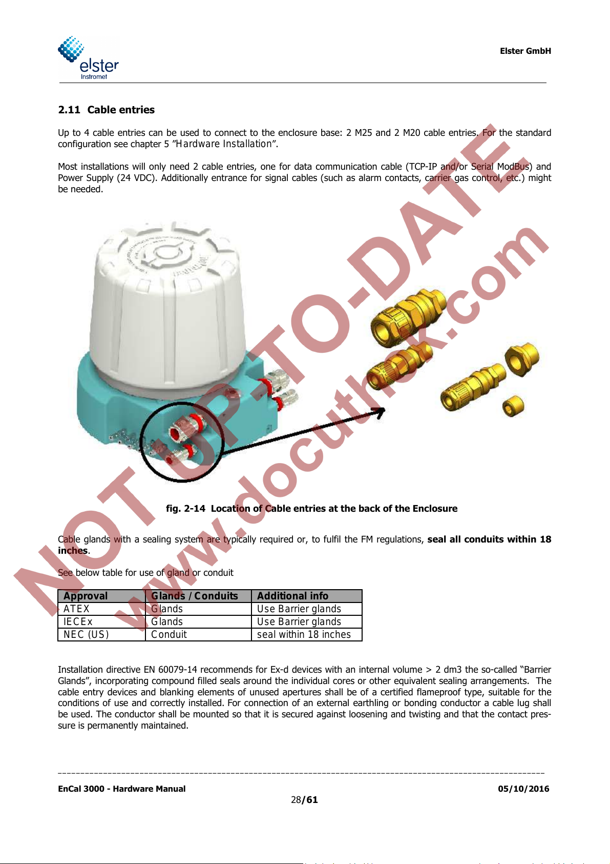
2.11 Cable entries
Up to 4 cable entries can be used to connect to the enclosure base: 2 M25 and 2 M20 cable entries. For the standard
configuration see chapter 5 ”
Most installations will only need 2 cable entries, one for data communication cable (TCP-IP and/or Serial ModBus) and
Power Supply (24 VDC). Additionally entrance for signal cables (such as alarm contacts, carrier gas control, etc.) might
be needed.
Hardware Installation
”.
Cable glands with a sealing system are typically required or, to fulfil the FM regulations, seal all conduits within 18
inches.
See below table for use of gland or conduit
ATEX
IECEx
NEC (US)
Installation directive EN 60079-14 recommends for Ex-d devices with an internal volume > 2 dm3 the so-called “Barrier
Glands”, incorporating compound filled seals around the individual cores or other equivalent sealing arrangements. The
cable entry devices and blanking elements of unused apertures shall be of a certified flameproof type, suitable for the
conditions of use and correctly installed. For connection of an external earthling or bonding conductor a cable lug shall
be used. The conductor shall be mounted so that it is secured against loosening and twisting and that the contact pres-
sure is permanently maintained.
fig. 2-14 Location of Cable entries at the back of the Enclosure
Glands
Glands
Conduit
Use Barrier glands
Use Barrier glands
seal within 18 inches
___________________________________________________________________________________________________________
EnCal 3000 - Hardware Manual 05/10/2016
28/61

Elster GmbH
2.12 External Switch
To comply with Electrical Safety Standards IEC 60947-1 and IEC 60947-3, an external switch has to be located close to
the analyser, enabling an operator to close down the unit in case of emergency. It has to be marked with "Disconnecting
Device". Practical implementation of this requirement will differ from site to site. In any case the external switch installa-
tion has to comply with all national, local, and company codes applicable to the location.
___________________________________________________________________________________________________________
EnCal 3000 - Hardware Manual 05/10/2016
29/61

Elster GmbH
2.13 Configuration with two Carrier Gases
For some applications like the analysis of biogas a use of different carrier gases for the two analytical modules can be an
advantage. In the application Biogas for the module from type mole sieve Argon is used as carrier gas and for the sec-
ond module from type PPU Helium is used as carrier gas. In the following picture this configuration is shown. The two
connections for the two different carrier gases are marked on the housing.
fig. 2-16
Configuration with two Carrier Gases
___________________________________________________________________________________________________________
EnCal 3000 - Hardware Manual 05/10/2016
30/61

IP 66
Mechanical
Electrical
Software
3 Technical Specifications
See below the main technical specifications.
Dimensions Base Ø 37 cm x Height 37 cm (Ø 14” x Height 14”)
Installation Clearance Ø 55 cm x Height 70 cm (Ø 20” x Height 28”)
Weight <30 kg
Safety Approvals ATEX : II 2 G Ex-d IIC T6 Gb
NEC : Class I/Zone 1 AEx db IIC T6
Power Supply 24 VDC, 50W nominal non-heated and 120 W nominal heated version (ambient < 0 °C)
Interfaces Ethernet UTP 10 Base-T for ModBus TCP/IP and PC link
Battery back-up Button battery, Panasonic Type BR 2032 3V
EMC according to EN 61000-6-2 and EN 61000-6-4
IECEx : Ex-d IIC T6 Gb
INMETRO:
NEC : Class I/Div. 1, Groups B, C & D
Created with Quint-PS-100-240AC / Quint-PS-24DC/24DC/10 / Siemens PSU / Siemens Logo
or equivalent power supplies. The power will be lower once the unit has reaches its operation
temperature depending on the ambient temperatures.
Two RS 232/485 ports (user selectable) for ModBus RTU
3 analogues I/O for local sensors (4-20 mA or 0-10 VDC)
Elster GmbH
Analyser ProTM: complete stand-alone operation, inclusive all calculations and generation of report for-
mats, without need for operator intervention. Calculations acc. to ISO 6976, GPA 2172 or GOST
22667
PC RGC 3000: Windows based program for configuration, diagnostics and report generation
(Compatible with Windows XP/Vista/7)
Data Logging History Log: local storage of last 35 days of all analytical data (analysis, events, alarms, aver-
ages, last chromatogram, calibration data) according to API Report 21.1. All data available on
remote workstation in XML format
DCS Remote monitoring and trending of the system as an integral part of the Instromet Supervi-
sory Suite
___________________________________________________________________________________________________________
EnCal 3000 - Hardware Manual 05/10/2016
31/61
Elster GmbH
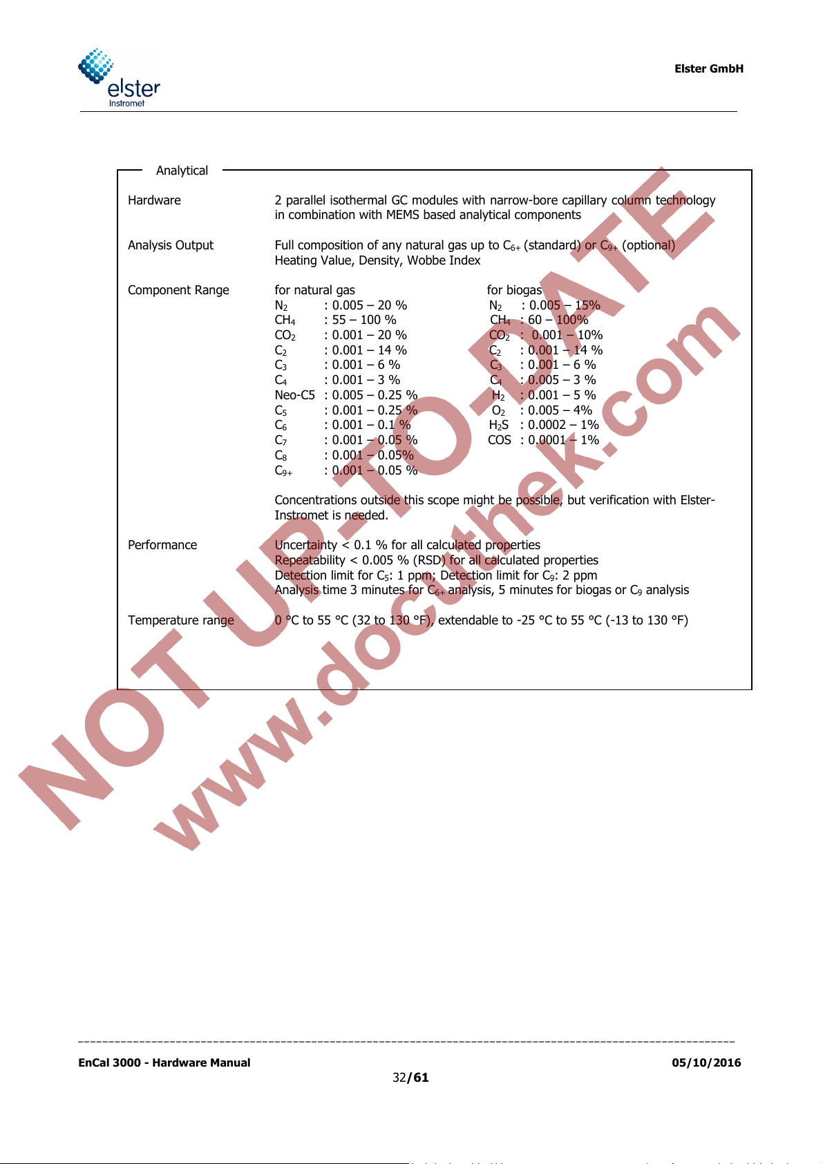
Analytical
Hardware 2 parallel isothermal GC modules with narrow-bore capillary column technology
Analysis Output Full composition of any natural gas up to C
Component Range for natural gas for biogas
Performance Uncertainty < 0.1 % for all calculated properties
Temperature range 0 °C to 55 °C (32 to 130 °F), extendable to -25 °C to 55 °C (-13 to 130 °F)
in combination with MEMS based analytical components
(standard) or C9+ (optional)
Heating Value, Density, Wobbe Index
N2 : 0.005 – 20 % N2 : 0.005 – 15%
CH4 : 55 – 100 % CH4 : 60 – 100%
CO2 : 0.001 – 20 % CO2 : 0.001 – 10%
C
C
C
Neo-C5 : 0.005 – 0.25 % H2 : 0.001 – 5 %
C
C
C
C
C
Concentrations outside this scope might be possible, but verification with Elster-
Instromet is needed.
Repeatability < 0.005 % (RSD) for all calculated properties
Detection limit for C5: 1 ppm; Detection limit for C9: 2 ppm
Analysis time 3 minutes for C
: 0.001 – 14 % C2 : 0.001 – 14 %
2
: 0.001 – 6 % C3 : 0.001 – 6 %
3
: 0.001 – 3 % C4 : 0.005 – 3 %
4
: 0.001 – 0.25 % O2 : 0.005 – 4%
5
: 0.001 – 0.1 % H2S : 0.0002 – 1%
6
: 0.001 – 0.05 % COS : 0.0001 – 1%
7
: 0.001 – 0.05%
8
: 0.001 – 0.05 %
9+
analysis, 5 minutes for biogas or C9 analysis
6+
6+
___________________________________________________________________________________________________________
EnCal 3000 - Hardware Manual 05/10/2016
32/61

Installation
Gas Cylinders
Helium / Argon Quality 5.0 or better
Optional 2 bottles with automatic change system
Supply pressure 5.5 barg
Flow ± 4 ml/min per column (max. 8 ml/min with 2 columns)
Calibration gas Composition preferably close to pipe line composition
Quality 2.0 or higher
(with a maximal uncertainty of 1% relative deviation for each component)
Supply pressure 1 to 4 barg nominal
Pressure peak protection up to 4 barg
Flow ± 30 ml/min
Elster GmbH
Location Outdoor installation, close to sample point. Only sun shade required
Mounting Preference is wall mounting using the bracket we supply
Gas connections Swagelok 1/8” or 3 mm
Electrical connections Power Supply / Data Communication / Ext. sensors (optional)
M20/M25 cable gland for armoured cable per default
Diameters Ø 5.5-12 mm / Ø 12.5-20 mm / Ø 17-26 mm
Optionally with adapters to NPT or other sizes.
___________________________________________________________________________________________________________
EnCal 3000 - Hardware Manual 05/10/2016
33/61

Elster GmbH
4 Data Communication
4.1 Local TCP/IP Data Communication
The main Data Communication Port of the EnCal 3000 is the TCP/IP port, although 2 serial ModBus ports are also avail-
able (see next paragraph). The TCP/IP Port (Ethernet UTP 10 Base-T) is necessary for connection with RGC 3000 (Win-
dows based interface for configuration, diagnostics and report generation), but is also used by preference for ModBus
communication with Flow Computers, PLC and other ModBus hosts, if they are able to handle ModBus TCP/IP. If not,
ModBus serial to TCP/IP are easily available nowadays. For existing systems the 2 serial ModBus ports can of course also
be used.
The picture below shows a typical set-up:
Conversion of RS-485
or 232 to TCP/IP
fig. 4-1 Typical Data Communication Set-up for Ethernet Communication with the EnCal 3000
___________________________________________________________________________________________________________
EnCal 3000 - Hardware Manual 05/10/2016
34/61

Elster GmbH
4.2 Local Serial ModBus Data Communication
Flow computers or another ModBus host could also be directly connected to one of the 2 serial ModBus ports internally
integrated in the EnCal 3000.
fig. 4-2 Typical Data Communication Set-up for TCP/IP combined
with Serial ModBus Communication with the EnCal 3000
___________________________________________________________________________________________________________
EnCal 3000 - Hardware Manual 05/10/2016
35/61

Elster GmbH
4.3 Remote Access
The schematic below shows the different options for remote access to the EnCal 3000:
Through Internet:
Or through a direct connection of the Ethernet switch with Internet (through cable or ADSL modem, or wire-
less)
Or through a VPN connection with the customer’s network, if the Ethernet switch or the local PC is integrated in
this network. In this case the customer has to give (if required only temporarily) a User Account and Login ID
to the remote PC.
If network connection is not available, telephone line connection is also possible:
Or by using an Ethernet modem with dial-in capability
Or by using the internal modem of the local PC, and a remote access program like PC Anywhere.
fig. 4-3 Remote Access to the EnCal 3000
___________________________________________________________________________________________________________
EnCal 3000 - Hardware Manual 05/10/2016
36/61
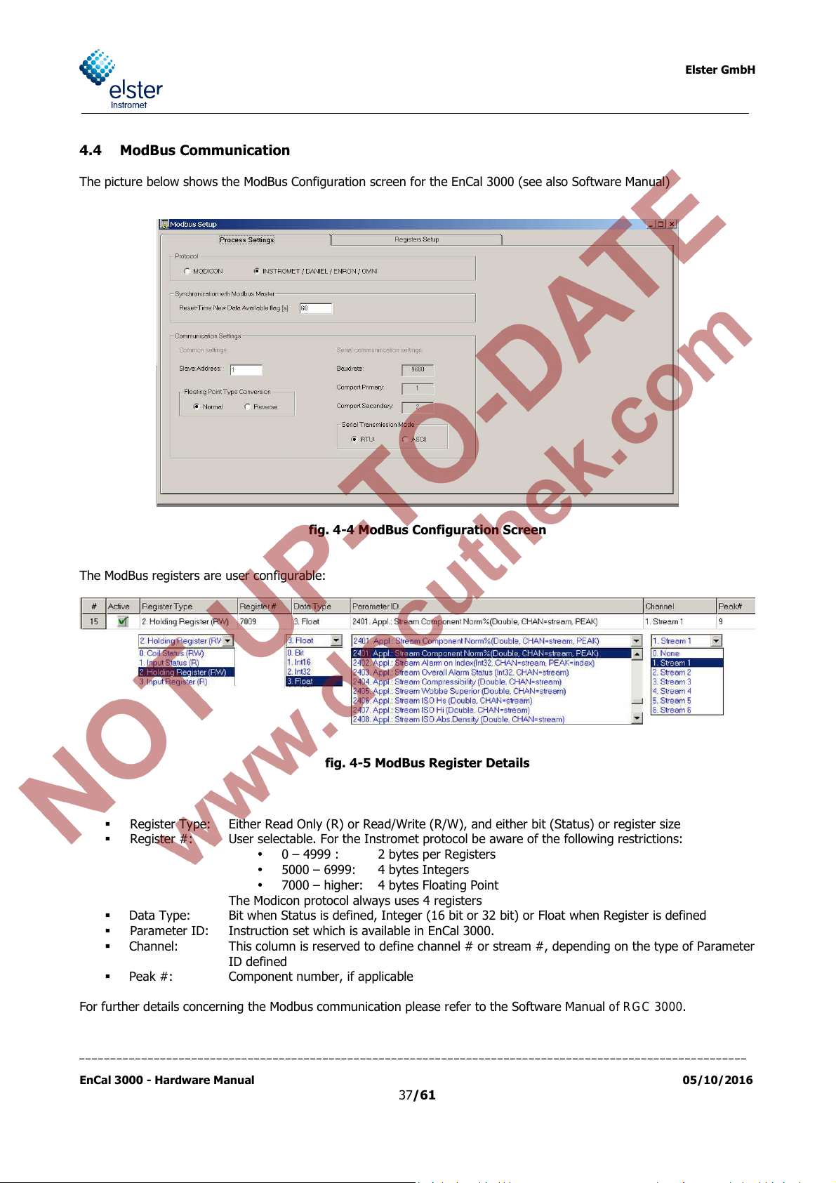
4.4 ModBus Communication
The picture below shows the ModBus Configuration screen for the EnCal 3000 (see also Software Manual)
Elster GmbH
fig. 4-4 ModBus Configuration Screen
The ModBus registers are user configurable:
fig. 4-5 ModBus Register Details
Register Type: Either Read Only (R) or Read/Write (R/W), and either bit (Status) or register size
Register #: User selectable. For the Instromet protocol be aware of the following restrictions:
• 0 – 4999 : 2 bytes per Registers
• 5000 – 6999: 4 bytes Integers
• 7000 – higher: 4 bytes Floating Point
The Modicon protocol always uses 4 registers
Data Type: Bit when Status is defined, Integer (16 bit or 32 bit) or Float when Register is defined
Parameter ID: Instruction set which is available in EnCal 3000.
Channel: This column is reserved to define channel # or stream #, depending on the type of Parameter
ID defined
Peak #: Component number, if applicable
For further details concerning the Modbus communication please refer to the Software Manual of RGC 3000.
___________________________________________________________________________________________________________
EnCal 3000 - Hardware Manual 05/10/2016
37/61

Elster GmbH
5 Hardware Installation
5.1 Installation specifications
Installations in the US shall comply with the relevant requirements of the National Electrical Code®
(ANSI/NFPA-70 (NEC®). Europe installations shall comply with the 60079-14 according the attached certifi-
cates
5.1.1 Weight and Dimensions
Weight: < 30 kg
Dimensions: Analyser : Ø 37 x H 37 cm (Ø 14.5" x H 14.5”)
Installation Clearance : Ø 50 x H 70 cm (Ø 20" x H 28”)
5.1.2 Installation clearance
fig. 5-1 Mounting Dimensions and Installation Clearance
fig. 5-2 Mounting Holes EnCal 3000 Housing
___________________________________________________________________________________________________________
EnCal 3000 - Hardware Manual 05/10/2016
38/61
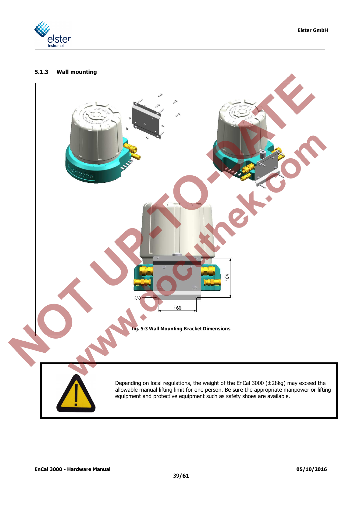
5.1.3 Wall mounting
Elster GmbH
fig. 5-3 Wall Mounting Bracket Dimensions
Depending on local regulations, the weight of the EnCal 3000 (±28kg) may exceed the
allowable manual lifting limit for one person. Be sure the appropriate manpower or lifting
equipment and protective equipment such as safety shoes are available.
___________________________________________________________________________________________________________
EnCal 3000 - Hardware Manual 05/10/2016
39/61

Elster GmbH
5.1.4 Connection of utilities
Gas lines: Carrier 1: HE Helium 5-6 barg (71-86 PSIg) Recommended pressure 5.5 barg
Carrier 2: AR Argon 5-6 barg (71-86 PSIg) Recommended pressure 5.5 barg
(Second carrier gas only needed to analyse biogas or hy-
drogen in natural gas. In standard applications this con-
nection is not used and closed without piping inside.)
STR1 Stream 1 1-4 barg (15-57 PSIg)
STR2 Stream 2 1-4 barg (15-57 PSIg)
STR3 Stream 3 1-4 barg (15-57 PSIg)
STR4 Stream 4 1-4 barg (15-57 PSIg)
STR5 Stream 5 1-4 barg (15-57 PSIg)
CAL Calibration Gas 1-4 barg (15-57 PSIg)
PV Purge Vent
SBV Sample + Block and Bleed Vent
All gas and vent lines do have a 1/8” Swagelok connection to the EnCal 3000. On request also 3 mm connections are
available.
fig. 5-4 Connections to the EnCal 3000
Power Supply cable
24 VDC / 120 W max
Conductor cross section: AWG 12-13 (2.5 - 4 mm²)
Armoured cable required for outdoor installation – OD between 12 and 25 mm
Data Communication
Ethernet : shielded twisted 4 wire cable or industrial CAT5
ModBus Serial : shielded twisted pair
All input, output signals and power connections shall be of non-hazardous voltage
and reinforced isolated from main.
___________________________________________________________________________________________________________
EnCal 3000 - Hardware Manual 05/10/2016
40/61

Elster GmbH
Processor board connection
Dip Switch Power supply valves
5.1.5 Connections to the EnCal 3000 Interconnection board
The drawing below shows the top lay-out of the Interconnection Board at the bottom of the unit. It contains all the con-
nectors for external cables (marked with grey). For flame retardant wiring use cables according an ISO norm. To fulfill
the FM regulations always use cables / wiring according to UL94 V-1 or equal for installation. All the wiring with the
other electronic boards is done in the factory, and may not be changed during field installation.
fig. 5-5 Interconnection Board: top view lay-out
J1
J2
J3
J4
J5
Channel 1 Connector
Channel 2 Connector
I/O Flat cable to Processor board
TCP/IP connection between Inter-
connection board and Processor board
J6
J7
J8
J9
J10
J11
Modbus RS485/232 connections
Ethernet connection
Solenoids terminal power suppl. 24 V DC
Power supply out (12 VDC / 24 VDC)
Analogue inputs (0-10 V DC)
Solenoids terminal for valves of
stream selection (0-12 V DC)
J12
J13
Power supply heater 1 (24 V DC)
Power supply heater 2
(24 V DC)
J14
J15
J17
J18
J19
F106
F107
LD101
LD102
LK 301-304
(internal current supply circuit)
Digital Inputs (passive contact)
Fan1 power supply connection (12 V DC)
Fan2 power supply connection (12 V DC)
Input
Fuse analytical channels Module (6,3A)
Fuse additional cabinet heaters (5A)
LED (internal 12 V- circuit)
LED (activation valves stream selection)
4 jumper for selection between
RS232 and RS485
LK 305-307 3
(4-20 mA or 0-10 V)
jumper for selection of analogue input
___________________________________________________________________________________________________________
EnCal 3000 - Hardware Manual 05/10/2016
41/61

Elster GmbH
Power Supply Connection:
Power Supply is 24 VDC , with conductor size AWG 12-13 (2.5 – 4 mm²). The cable has to be connected to connector
J8. See picture below and
connect a third wire for the ground. Instead of that the device should be grounded at the bottom of one housing at a M5
connection or at a free M8 connection at the mounting plate.
fig. 5-6
for location and polarity. Just a two wire connection for + and – is required, don’t
fig. 5-6 Location of Power Supply connector (J8)
Ethernet connection:
The Ethernet connection is used for connection with a PC or ModBus TCP/IP clients. It uses 4 wires, connected to con-
nector J10. See picture below for location and wiring scheme.
fig. 5-7 Location of Ethernet connector (J10) and wiring scheme
___________________________________________________________________________________________________________
EnCal 3000 - Hardware Manual 05/10/2016
42/61

Serial ModBus connection
The Serial ModBus connection is used for connection with Serial ModBus clients like for example Flow Comput-
ers. The EnCal features 2 Serial ModBus ports with identical output. They are both independently configurable
for RS232 or RS485 communication through link settings 301 to 304 (see pictures below for location, wiring
scheme and link settings).
Elster GmbH
fig. 5-8 Location of Serial ModBus connector (J6)
___________________________________________________________________________________________________________
EnCal 3000 - Hardware Manual 05/10/2016
fig. 5-9 Modbus Connection and Link settings
43/61

5.2 Hardware Start-up
Electrical Installation in Hazardous Areas
The start-up should be done by an experienced technician, with a proven knowledge of electrical instal-
lations in explosion proof areas. Always remember to make sure there is no hazardous condition pre-
sent during installation. Follow the instructions below carefully and make sure you have fulfilled all nec-
essary safety steps before powering up the EnCal 3000.
Gas connections:
Make sure the helium cylinder is tightly secured to the wall and the regulators are tightly mounted on the
cylinder. Check the helium and Argon quality (5.0 – equivalent to Zero Grade classification - or better). Do
not connect yet the tubing to the helium inlet at the EnCal 3000. Open carefully the helium regulator and
check the helium pressure at the outlet of the regulator. Adjust to 5.5 barg (80 psig). Purge the tubing be-
fore connecting to the EnCal 3000 for about 30 s. Make the connection with Helium inlet. Check for leaks.
Make sure the cal. gas cylinder is tightly secured to the wall and the regulators tightly mounted on the cyl-
inder. Check the cal. gas certificate. The tube should be flushed once before it is connected to the En-
cal3000 with a non-flammable gas like the carrier gas Helium. Open carefully the cal. gas regulator and
check the cal. gas pressure at the outlet of the regulator. Adjust to 1-4 barg (15-57 psig). Purge the tubing
before connecting to the EnCal 3000 for about 30 seconds. After the connection a check for leaks is re-
quired.
Check the stream gas pressure at the connection point with the EnCal 3000. Adjust to 1-4 barg (15-57
psig). Purge the tubing before connecting to the EnCal 3000 for about 30 s. Make the connection with inlet
STR1. Check for leaks. (calibration is already connected in the section above)
Make a careful leak check of the total system.
Make sure that the sample gas flow is nowhere blocked. To be able to guarantee this the Encal3000GC has
to use a separate Vent line which doesn’t become blocked by any kind of restriction. The Vent lines PV and
SBV can be combined to one vent line.
Power Supply cable:
Standard industrial 2-wire cable.
(The use of an external junction box is responsibility of the customer / installer)
Power rating 3A x 24V nominal (ambient T > 0 °C or >32 °F). The cable cross-section must be chosen suf-
ficiently large.
For the location of the internal connector see figure 5.6.
Data communication cable:
Ethernet cable (PC and/or ModBus TCP/IP clients) :
Standard straight cable, shielded twisted 4 wire cable or industrial CAT5 quality. For the location of the
Ethernet connector see figure 5.7.
Serial Modbus :
o Standard industrial data communication cable twisted pair
3-wire for RS 485 communication
3-wire for RS 232 communication
o 2 serial ModBus ports are available, each of them independently user configurable into RS 232 or 485
(Pin lay-out and link locations see figures 5.8 and 5.9)
___________________________________________________________________________________________________________
EnCal 3000 - Hardware Manual 05/10/2016
44/61
Elster GmbH
Elster GmbH
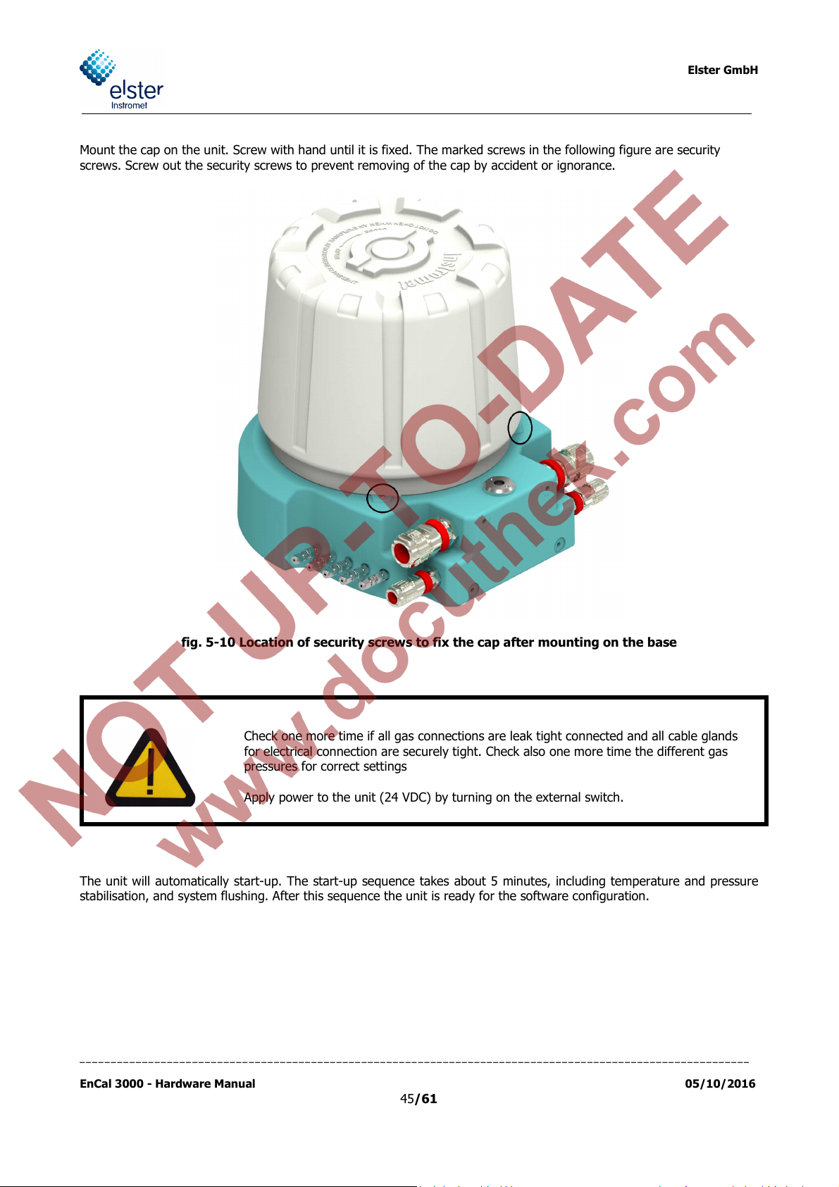
Mount the cap on the unit. Screw with hand until it is fixed. The marked screws in the following figure are security
screws. Screw out the security screws to prevent removing of the cap by accident or ignorance.
fig. 5-10 Location of security screws to fix the cap after mounting on the base
Check one more time if all gas connections are leak tight connected and all cable glands
for electrical connection are securely tight. Check also one more time the different gas
pressures for correct settings
Apply power to the unit (24 VDC) by turning on the external switch.
The unit will automatically start-up. The start-up sequence takes about 5 minutes, including temperature and pressure
stabilisation, and system flushing. After this sequence the unit is ready for the software configuration.
___________________________________________________________________________________________________________
EnCal 3000 - Hardware Manual 05/10/2016
45/61

Elster GmbH
HT Heaters installed
Frost protection has been added to keep the internals in the housing
SC Single Channel
QS Quad Slave
This housing is the slave (2nd dome) housing of an EnCal 3000 Quad. It
H2 Hydrogen
This analyser is configured to work with Hydrogen as carrier gas. As
such
APPENDIX 1: Possible hardware options of the EnCal 3000
The EnCal 3000 can be delivered with several options. These options are described in the following seg-
ments of this appendix.
Option
Position of the type indication:
Meaning Explanation
above 0 degrees Celsius
This a single channel analyser
has no CPU board inside.
it needs venting of the carrier to safe area.
___________________________________________________________________________________________________________
EnCal 3000 - Hardware Manual 05/10/2016
46/61
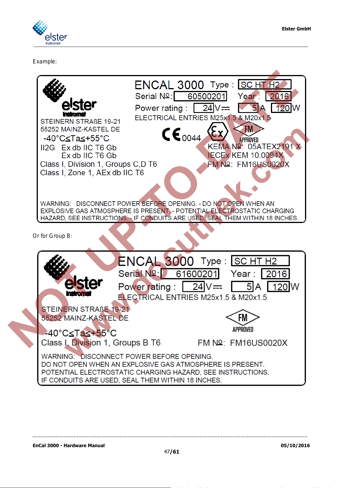
Example:
Elster GmbH
Or for Group B:
___________________________________________________________________________________________________________
EnCal 3000 - Hardware Manual 05/10/2016
47/61
Elster GmbH
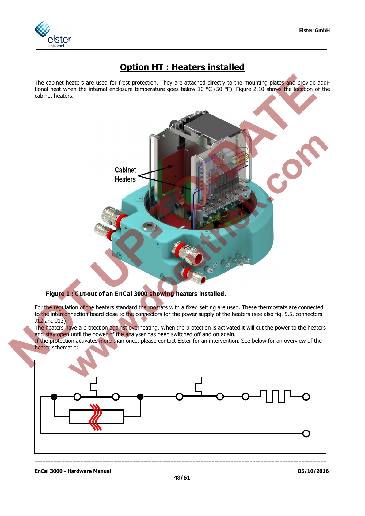
Option HT : Heaters installed
The cabinet heaters are used for frost protection. They are attached directly to the mounting plates and provide addi-
tional heat when the internal enclosure temperature goes below 10 °C (50 °F). Figure 2.10 shows the location of the
cabinet heaters.
Figure 1 : Cut-out of an EnCal 3000 showing heaters installed.
For the regulation of the heaters standard thermostats with a fixed setting are used. These thermostats are connected
to the interconnection board close to the connectors for the power supply of the heaters (see also fig. 5.5, connectors
J12 and J13).
The heaters have a protection against overheating. When the protection is activated it will cut the power to the heaters
and stay open until the power of the analyser has been switched off and on again.
If the protection activates more than once, please contact Elster for an intervention. See below for an overview of the
heater schematic:
___________________________________________________________________________________________________________
EnCal 3000 - Hardware Manual 05/10/2016
48/61

Elster GmbH
Option SC : Single Channel analyser
Whenever option SC is on the nameplate of the analyser, this will indicate that this EnCal will only have one
channel installed in the housing. This is the case when, for instance, the EnCal 3000 is used to measure a
single component only (like H2S or THT).
Figure 2 : Cut-out of an EnCal 3000 showing one channel installed
___________________________________________________________________________________________________________
EnCal 3000 - Hardware Manual 05/10/2016
49/61
Elster GmbH
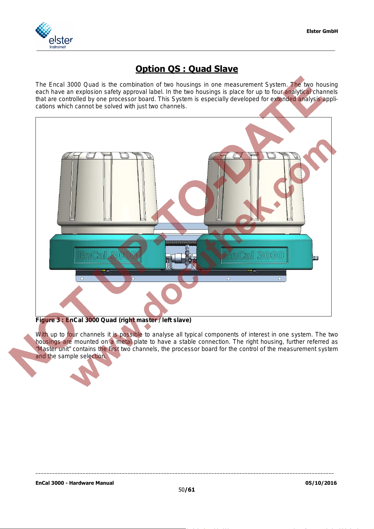
Option QS : Quad Slave
The Encal 3000 Quad is the combination of two housings in one measurement System. The two housing
each have an explosion safety approval label. In the two housings is place for up to four analytical channels
that are controlled by one processor board. This System is especially developed for extended analysis appli-
cations which cannot be solved with just two channels.
Figure 3 : EnCal 3000 Quad (right master / left slave)
With up to four channels it is possible to analyse all typical components of interest in one system. The two
housings are mounted on a metal plate to have a stable connection. The right housing, further referred as
“Master unit” contains the first two channels, the processor board for the control of the measurement system
and the sample selection.
___________________________________________________________________________________________________________
EnCal 3000 - Hardware Manual 05/10/2016
50/61

Elster GmbH
Figure 4 : Quad with open covers
The other housing, further referred as “Slave unit” contains the third and optionally fourth channel (depend-
ing in the application).
It has no CPU board inside. It is labelled as “QS” on the Safety approval label.
Both housings have a separate power supply board (interconnection board). The slave unit shares the output
of the stream selection in the master unit and therefore no additional stream selection is needed.
The required gas connections between the two housings are preinstalled.
___________________________________________________________________________________________________________
EnCal 3000 - Hardware Manual 05/10/2016
51/61

Elster GmbH
Option H2 : Hydrogen carrier gas
This analyser is configured to work with Hydrogen as carrier gas. Normally the carrier gas is a non-explosive
one (Helium / nitrogen / Argon) and it is purged inside the housing to keep the atmosphere in the housing
clean. However with hydrogen we cannot do that since it might cause an explosive atmosphere. As such it
needs venting of the carrier to safe area.
There is a vent connection marked “column vent” that should be connected to a vent going to safe area with-
out restriction or back pressure.
___________________________________________________________________________________________________________
EnCal 3000 - Hardware Manual 05/10/2016
52/61

APPENDIX 2: DECLARATION OF CONFORMITY ENCAL 3000
Elster GmbH
___________________________________________________________________________________________________________
EnCal 3000 - Hardware Manual 05/10/2016
53/61

Elster GmbH
___________________________________________________________________________________________________________
EnCal 3000 - Hardware Manual 05/10/2016
54/61

Elster GmbH
___________________________________________________________________________________________________________
EnCal 3000 - Hardware Manual 05/10/2016
55/61

Elster GmbH
___________________________________________________________________________________________________________
EnCal 3000 - Hardware Manual 05/10/2016
56/61

APPENDIX 3: CERTIFICATE EC-Type Examination
Elster GmbH
___________________________________________________________________________________________________________
EnCal 3000 - Hardware Manual 05/10/2016
57/61

Elster GmbH
___________________________________________________________________________________________________________
EnCal 3000 - Hardware Manual 05/10/2016
58/61

Elster GmbH
___________________________________________________________________________________________________________
EnCal 3000 - Hardware Manual 05/10/2016
59/61

Elster- Instromet BV
___________________________________________________________________________________________________________
EnCal 3000 – Hardware Manual 05/10/2016
60/61

Elster- Instromet BV
___________________________________________________________________________________________________________
EnCal 3000 – Hardware Manual 05/10/2016
61/61
 Loading...