


EK260
Volume Conversion Device EK260
Operating Manual and Installation Instructions
Operating Manual: 73016960 SW Version: from V2.52
Issued: 13.03.08 (p) Edition:

Volume Conversion Device EK260
All rights reserved.
Copyright © 2008 Elster GmbH, D-55252 Mainz-Kastel
All the figures and descriptions in this operating and instruction manual have been
compiled only after careful checking. Despite this however, the possibility of errors cannot
be completely eliminated. Therefore, no guarantee can be given for completeness or for
the content. Also, the manual cannot be taken as giving assurance with regard to product
characteristics. Furthermore, characteristics are also described in it that are only available
as options.
The right is reserved to make changes in the course of technical development. We would
be very grateful for suggestions for improvement and notification of any errors, etc.
With regard to extended product liability the data and material characteristics given
should only be taken as guide values and must always be individually checked and
corrected where applicable. This particularly applies where safety aspects must be
taken into account.
You can obtain further support from the branch or representative responsible for your area.
You will find the address in the Internet or simply enquire at Elster GmbH.
Passing this manual to third parties and its duplication, in full or in part, are only allowed
with written permission from Elster GmbH.
The guarantee becomes invalid if the product described here is not handled properly,
repaired or modified by unauthorised persons or if replacement parts which are not
genuine parts from Elster GmbH are used.
Mainz-Kastel, March 2008
2 Elster GmbH

Volume Conversion Device EK260
Contents
I Safety instructions.......................................................................................................5
II Items supplied and accessories.................................................................................6
1 Brief description ..........................................................................................................7
2 Operation......................................................................................................................9
2.1 Front panel...............................................................................................................9
2.2 Display...................................................................................................................10
2.2.1 Line 1 = Labels...........................................................................................................10
2.2.2 Line 2 = Value with name and unit ............................................................................. 12
2.3 Keypad...................................................................................................................13
2.3.1 Changing values ........................................................................................................14
2.3.2 Entering sources........................................................................................................15
2.3.3 Entry errors................................................................................................................15
2.4 Access rights..........................................................................................................16
2.4.1 Calibration lock ..........................................................................................................16
2.4.2 Calibration logbook ....................................................................................................17
2.4.3 Supplier's lock and customer's lock............................................................................ 17
2.5 Formation of the list structure.................................................................................17
3 Functional description...............................................................................................22
3.1 Standard Volume (Volume at base conditions) list.................................................23
3.2 Actual volume (volume at measurement conditions) list..........................................25
3.3 Pressure list...........................................................................................................28
3.4 Temperature list.....................................................................................................31
3.5 Volume corrector list ..............................................................................................34
3.6 Archive list..............................................................................................................37
3.6.1 Device numbers and channel numbers for WinView and WinLIS............................... 40
3.6.2 Find function for checking the archive entries............................................................. 40
3.7 Status list................................................................................................................41
3.7.1 List of status messages .............................................................................................. 44
3.7.2 Status register addresses........................................................................................... 50
3.8 System list..............................................................................................................51
3.9 Service list..............................................................................................................53
3.10 Input list..................................................................................................................58
3.11 Output list...............................................................................................................64
3.11.1 Parameterising the HF output .................................................................................... 69
3.11.2 Brief summary of output parameterisation..................................................................70
3.12 Interface list............................................................................................................71
3.12.1 Printer log ..................................................................................................................78
3.12.2 Automatic setting of the clock by remote data transmission .......................................80
3.12.3 Modbus parameters...................................................................................................82
3.13 Energy list ..............................................................................................................85
3.14 User list..................................................................................................................87
4 Applications ...............................................................................................................88
4.1 Rated operating conditions for the various conversion methods............................88
4.2 Application as high flow display device ..................................................................90
4.3 Application as flow recording device......................................................................91
4.4 Connection of a counter with LF pulse transmitter .................................................91
4.5 Connecting a meter with encoder...........................................................................92
Elster GmbH 3

Volume Conversion Device EK260
4.6 Application in areas subject to explosion hazards ................................................. 93
4.6.1 Applications in Zone 1................................................................................................ 93
4.6.2 Applications in Zone 2................................................................................................ 93
4.7 Applications for Interface 2.................................................................................... 94
4.7.1 Modem with control signals (standard modem) .......................................................... 94
4.7.2 Modem without control signals................................................................................... 94
4.7.3 FE260 Function Expansion with modem ....................................................................95
4.7.4 FE260 Function Expansion without modem ............................................................... 95
4.7.5 FE230 Function Expansion with modem ....................................................................95
4.7.6 Printer on the EK260 or on an FE260.........................................................................96
4.7.7 Other device with RS232 interface (e.g. PC).............................................................. 96
4.7.8 Modbus protocol.........................................................................................................96
4.7.9 Sending short messages by SMS...............................................................................97
4.7.10 Standard output data records for process data ("three-minute values")...................... 97
5 Installation and maintenance ................................................................................... 99
5.1 Installation procedure ............................................................................................ 99
5.2 Mounting.............................................................................................................. 100
5.2.1 Wall mounting ..........................................................................................................100
5.2.2 Meter superstructure................................................................................................ 101
5.3 Cable connection and earthing............................................................................ 102
5.4 Terminal layout.................................................................................................... 103
5.5 Connection of the serial interface ........................................................................ 105
5.5.1 Modem with control signals...................................................................................... 105
5.5.2 Modem without control signals.................................................................................106
5.5.3 Printer...................................................................................................................... 106
5.5.4 Other devices with RS-232 interface ........................................................................107
5.5.5 FE260 Function Expansion (optionally with modem)................................................ 107
5.5.6 FE230 Function Expansion ...................................................................................... 108
5.6 Connection of a low-frequency pulse transmitter (reed contacts) ........................ 108
5.7 Connection of an encoder.................................................................................... 109
5.8 Seals.................................................................................................................... 109
5.8.1 Seal layout of basic device....................................................................................... 110
5.8.2 Seal layout of temperature sensor............................................................................112
5.8.3 Sealing layout of pressure sensor ............................................................................113
5.9 Battery replacement............................................................................................. 114
A Approvals................................................................................................................. 116
A.1 EC Declaration of Conformance .......................................................................... 116
A.2 Approval for Ex Zone 1........................................................................................ 117
B Technical data ......................................................................................................... 122
B-1 General data (mechanical, terminals, ambient conditions).................................. 122
B-2 Batteries.............................................................................................................. 122
B-3 External power supply......................................................................................... 123
B-4 Pulse, status and encoder inputs......................................................................... 123
B-5 Signal and pulse outputs..................................................................................... 124
B-6 Optical serial interface......................................................................................... 124
B-7 Electrical serial interface (internal)....................................................................... 124
B-8 Pressure sensor .................................................................................................. 125
B-9 Temperature sensor ............................................................................................ 125
B-10 Measurement uncertainty .................................................................................... 125
C Index......................................................................................................................... 126
4 Elster GmbH

Volume Conversion Device EK260
I Safety instructions
F The connections of the EK260 are freely accessible during setting up. Therefore, make
sure that no electrostatic discharge (ESD) can occur in order to avoid damage to the
components. The person carrying out the installation can, for example, discharge
himself/herself by touching the potential equalisation line.
F To avoid erroneous operation and problems, the operating manual must be read
before putting the EK260 into operation.
The EK260 Volume Conversion Device(Volume Conversion Device) is suitable for
applications in Ex Zone 1 for gases in the temperature class T4 (ignition temperature >
135°C, e.g. natural gas) according to VDE 0170. (see Appendix A-2)
In this application it is essential to take note of the following information:
F Follow the regulations in the relevant standards, in particular DIN EN 60079-14 (VDE
0165 Part 1) and DIN EN 50014.
F Make sure that the limits quoted in the certificate of conformance (see Appendix A-2) for
the devices to be connected are not exceeded.
F The housing of the EK260 must be earthed directly to a potential equalisation strip. A
terminal screw is provided for this on the left housing wall.
Elster GmbH 5

Volume Conversion Device EK260
II Items supplied and accessories
Items supplied:
The items supplied with the EK260 include:
a) EK260 Volume Conversion Device
b) Dispatch list
c) Configuration data sheet
d) Operating Manual
e) 3 blind insertion seals for gland-type cable entries
f) Lead sleeves for sealing the pressure connection.
Ordering information and accessories
• EK260 Volume Conversion Device, complete
• EBL 50 Thermowell, complete with M10 x 1 weld-in sleeve
• EBL 67 Thermowell, complete with M10 x 1 weld-in sleeve
• EBL 160 Thermowell, complete with G 3/4" weld-in sleeve and sealing ring
• EBL 250 Thermowell, complete with G 3/4" weld-in sleeve and sealing ring
• Three-way test tap
• Shut-off ball valve with Ermeto 6L test connection
• Minimess test connection
• Operating manual, German
• Operating manual, English
• Operating manual, French
• Plug-in terminal, 2-pole black
• Calibration covering cap
Order no.
83 462 140
73 012 634
73 014 456
73 012 100
73 012 100
73 008 403
73 016 166
73 016 167
73 016 960
73 017 115
73 017 218
04 130 407
73 016 879
• Battery module, 13 Ah
6 Elster GmbH
73 015 774

Volume Conversion Device EK260
1 Brief description
The EK260 Volume Conversion Device is used for the conversion of the gas volume
measured at line conditions by a gas meter into the base conditions and into the
appropriate energy.
The pressure and temperature are measured for the determination of the line conditions.
The inverted compressibility factor ratio (K-value) can alternatively be calculated according
to S-GERG 88 or AGA-NX19 or it can be entered as a constant. The volume is converted
into energy using the adjustable calorific value.
The integral recording device contains meter readings and maxima from the last
15 months and the consumption profile of the last 9 months for a measurement period of
60 minutes.
Power supply:
• Battery operation with a service life depending on operating mode ≥ 5 years.
• Optional double battery life is possible by connection of an additional battery pack.
• Battery replacement possible without loss of data and without violation of calibration seals.
• Data retention without battery supply due to internal EEPROM.
• Connection for external power supply unit.
Operator interface:
• Alphanumeric display with two lines of 16 characters.
• A display list freely assignable by the user.
• Programming via keypad possible.
• Calibration switch (separately sealed in the device).
• Calibration logbook according to PTB-A 50.7 for changing values relevant to calibration
without the calibration lock.
• Two user locks (supplier's and customer's locks) with numerical codes.
• Access rights for each individual value can be set separately via interface (with appropriate
rights).
Counter / signal inputs:
• 3 inputs for reed contacts or transistor switches, programmable as pulse or signal inputs.
• Connection provided for an Elster GmbH C1 Encoder Counter for digital transmission of
genuine counter readings (also in battery mode).
• Maximum counting frequency 2 Hz (adjustable).
• Pulse value for each input separately adjustable, also non-decade.
• Various counters for Vb and Vm and for each input (main counter, original counter,
disturbance volumes, totaliser, adj. counter, measurement period counter, day counter).
• Each input can be separately sealed and secured under official calibration.
Pulse / signal outputs:
• 4 programmable transistor outputs, each freely programmable as alarm / warning output,
pulse output, signal output for limit monitoring.
• Each output can be separately sealed and secured under official calibration.
Elster GmbH 7

Volume Conversion Device EK260
Data interface:
• Optical interface according to IEC 62056-21 (replaces IEC 61107 and EN61107).
• Permanently wired serial interface (RS232 or RS485).
• MODBUS protocol via the permanently wired serial interface.
• Automatic setting of the clock by remote data transmission with a modem connected.
• Sending short messages by SMS.
• Programmable standard output data records for process data ("three-minute values").
Pressure and temperature sensors:
• Pressure sensor type CT30 integrated in device,or external mounted.
• Pt500 temperature sensor, variable length.
Mechanical details / housing:
• Suitable for wall mounting and meter installation (with mounting bracket).
• Mounting + device installation without breaking the calibration seals.
• Ambient temperature range: -25°C...+55°C
Extended temperature range with restricted functions possible.
Approvals:
• Approval by calibration authorities
- as Volume Conversion Device acc. MID-Directive 2004/22/EG,
- as flow recording device acc. PTB-A50.7,
- as high flow display device acc. PTB-A50.7.
• Ex approval for use in Ex Zone 1 according to EEx ib IIC T4.
Monitoring functions
• Monitoring of signalling inputs.
• Monitoring of any values with respect to programmable limits.
• All monitoring can trigger appropriate reactions such as for example, entries in the status
register, logbook or archives or signalling via outputs.
Archives
• Counter readings and maxima from the last 15 months for Vb and Vm.
• Mean values, maxima and minima from the last 15 months for pressure and temperature
as well as partially for the inverted compressibility factor ratio and conversion factor.
• Measurement period values (consumption profile) from the last 9 months for Vb, Vm, p, T,
K and C for a measurement period of 60 minutes. The measurement period can be set in
the range from 1 to 60 minutes.
• Automatic changeover to daylight saving time can be set.
• Event logbook with 250 entries for events such as for example status changes, signalling
inputs, limit violations.
• Changes logbook ("audit trail") with entry of the last 200 changes to settings
(parameterising steps).
8 Elster GmbH
Volume Conversion Device EK260
2 Operation
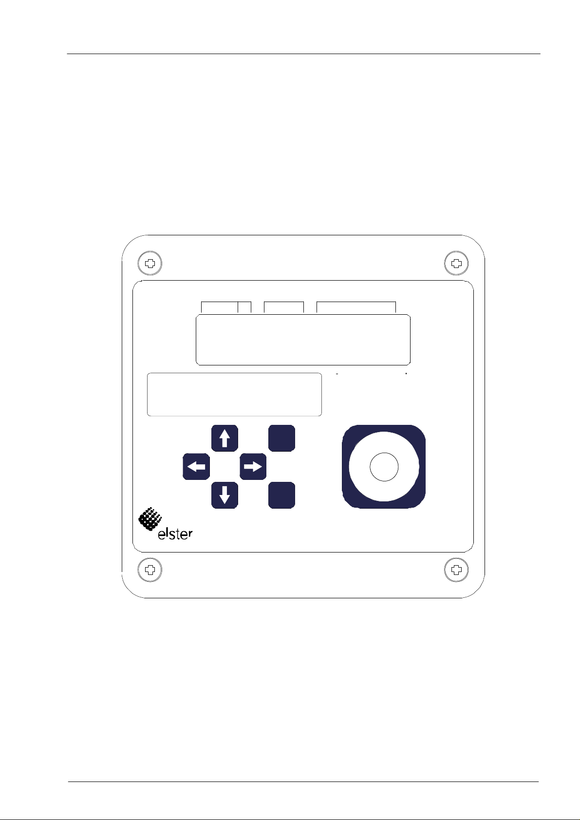
2.1 Front panel
The following are positioned on the front panel for operation:
• Two-line alphanumeric display with 16 characters per line.
• Six keys for the display and entry of values.
EK260
Arc. Status MenuPrefix
Instromet
Typenschild
Identification label
ESC
ENTER
Submenu
y
n
a
m
r
e
G
n
i
e
d
a
M
Elster GmbH 9

Volume Conversion Device EK260
2.2 Display
Basic display structure (with an example):
Prefix Archive
m a x á A W B V b
V b A 1 2 3 4 5 6 7 . 8
Both lines in the display are subdivided into fields which are described below.
Device status M e n u
à
m 3
Submenu
2.2.1 Line 1 = Labels
The first line is subdivided into five fields of which four are labelled on the front panel:
1. Prefix (Type of computation)
The type of computation identifies so-called "initial values" (also termed "capture values").
These are values which have been formed over a time period (e.g. the adjustable
measurement period or one month). Labels:
- max Maximum – highest value within the time range
- min Minimum – lowest value within the time range
- ∆ Change – volume within the time range
- ∅ Mean – mean within the time range
2. Archive
If an arrow points upwards to the label "Archive", then the displayed value is an archived
value. This was frozen at a defined point in time and cannot be changed.
10 Elster GmbH

Volume Conversion Device EK260
3. Device status
Here a maximum of three of the most important items of status information are continually
shown.
A flashing character signifies that the relevant state is still present and the relevant
message is present in the momentary status.
A non-flashing character signifies that the relevant state is past, but the message in the
status register has not yet been cleared.
Meaning of the letters:
- A "Alarm"
At least one status message has occurred which has resulted in disturbance
volumes being counted.
Basically, all messages with numbers in the range "1" and "2" represent alarms (e.g.
"Alarm limits for pressure or temperature violated" → 3.7).
Alarm messages are copied into the status register and are retained here, even after
rectification of the cause of the error, until they are manually cleared.
- W "Warning"
At least one status message has occurred which is valid as a warning.
Basically, all messages with numbers in the range "3" to "8" represent warnings (e.g.
"Warning limits for pressure or temperature violated" or "Error on output" → 3.7).
Warning messages are copied into the status register and are retained here, even
after rectification of the cause of the error, until they are manually cleared.
- B "Batteries flat"
The remaining battery service life is less than 3 months.
This display corresponds to the status message "Batt. low" (→ Page 48 ).
- L "Calibration logbook full"
The calibration logbook is full; some parameters can now only be changed with the
calibration lock open. (→PLogB, page 42)
This display corresponds to the status message "PLogB full", (→ page 0).
If the calibration lock is opened with the calibration logbook full, it can only be
F
closed again after clearing the calibration logbook.
- P "Programming mode"
The programming lock (calibration lock) is open.
This display corresponds to the status message "Cal.lock o." (→ Page 48 ).
- M "Measurement error"
The connected gas meter encoder does not supply a fault-free counter reading.
A flashing "M" corresponds to the status message "Coder fault" (→ Page 48 ).
- o "online"
A data transfer via the optical or permanently wired interface is running. In each case
the other interface cannot then be used.
This display corresponds to the status message "online" (→ Page 48 ).
4. Menu
Here is displayed to which list according to Chapter 3 the currently displayed value
belongs. In submenus (indicated by an arrow to the left, see below) its name is displayed
which is identical to the abbreviated designation of the entry point.
Elster GmbH 11

Volume Conversion Device EK260
∗ 1 2 3 4 5 6 7 . 8
5. Submenu
- → Arrow to the right
indicates that the displayed value is the entry point of a submenu. This can be
called with the key [ENTER].
- ← Arrow to the left
indicates that you are located in a submenu which can be quit with the key [ESC].
On pressing [ESC] you are returned to the entry point of the submenu.
2.2.2 Line 2 = Value with name and unit
In the second line the name, value and (when available) the unit of the data are always
shown.
Uncalibrated values are identified for the user with an asterisk ("∗") after the abbreviated
designation.
For use outside of applications subject to calibration, the device can also be obtained
without the identification of uncalibrated values.
Example of uncalibrated values:
V b A
Example of calibrated values:
V b
1 2 3 4 5 6 7 . 8
m 3
m 3
12 Elster GmbH
Volume Conversion Device EK260
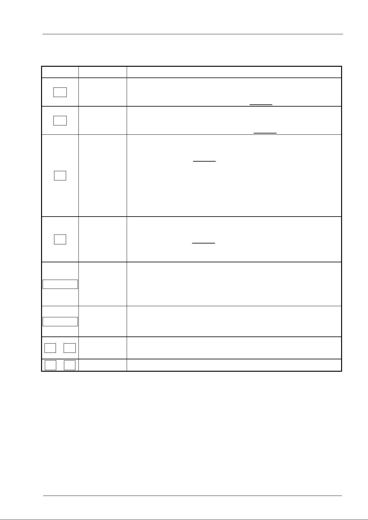
2.3 Keypad
Key(s) Designation Effect
↓
↑
→
←
Down cursor
key
Up cursor
key
Pfeil rechts
Left cursor
key
• Downwards movement within the list:
From the first value in the list movement is in the direction of
the last value or from the last value directly to the first one.
• Upwards movement within the list:
From the last value in the list movement is in the direction of
the first value or from the first value directly to the last one.
• Movement to the right to a different list:
From the first list movement is in the direction of the last list or
from the last list directly to the first one.
With similar lists (e.g.: Vb and Vm) skipping occurs to the
appropriate value, otherwise to the first value.
• Switchover to the second part of the value for values
displayed on two lines:
- Counter readings divided into pre- and post-decimal places.
- Date and time (together one value) divided.
• Movement to the left to a different list:
From the last list movement is in the direction of the first list or
from the first list directly to the last one. With similar lists (e.g.:
Vb and Vm) skipping occurs to the appropriate value,
otherwise to the first value in the adjacent list.
Depends on the value displayed (Data class, → 2.3.1)
• Activate the entry mode.
ENTER
Enter
• Open the submenu.
• Update measurement (by pressing twice).
• Return from a submenu to the entry point in the higher
ESC
Escape
level main menu.
• Cancel entry (the value remains unchanged).
• Skips to first value in the list
← + ↑
Home / Clear
• Updates a value in the entry mode
← + →
Help
• Displays the address (reference code) of the value
In the entry mode the keys change their functions, see Chapter 2.3.1.
Elster GmbH 13
Volume Conversion Device EK260
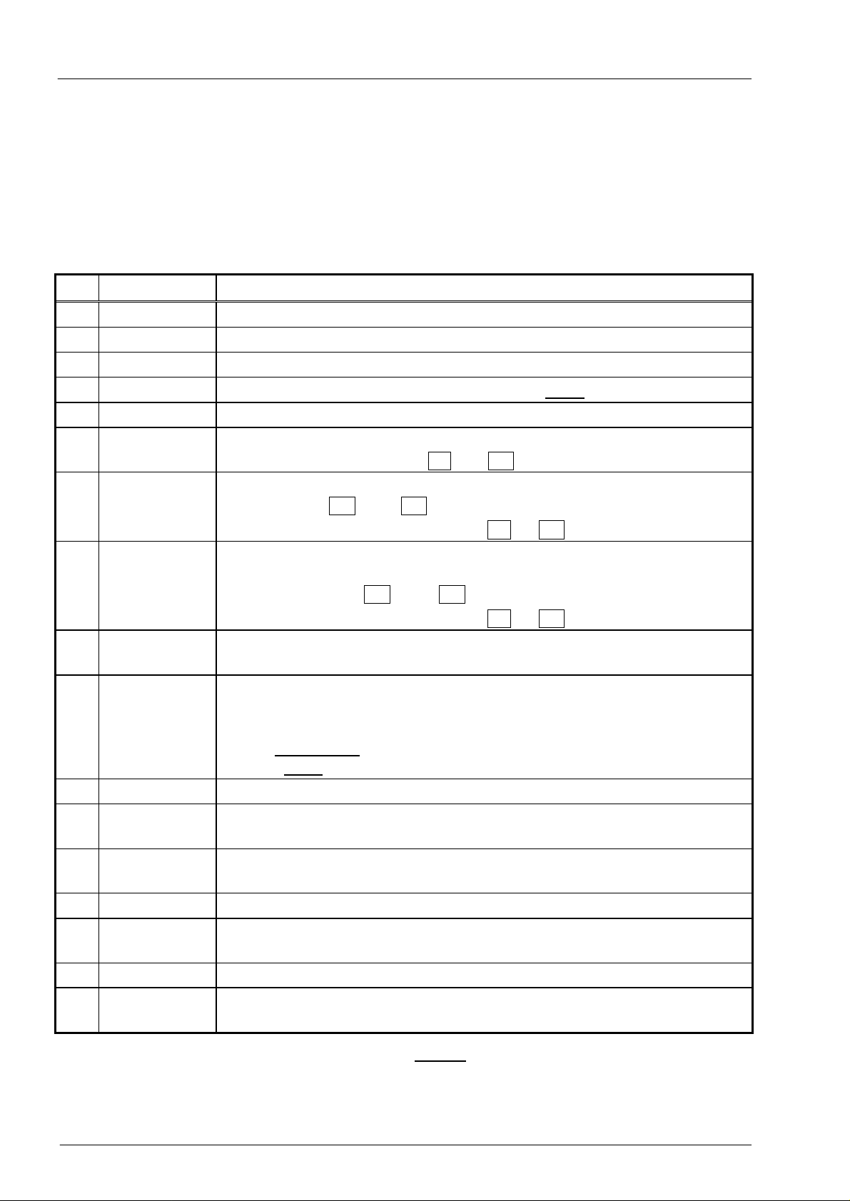
2.3.1 Changing values
The methods of entering and changing values differ depending on the value. These are
therefore subdivided into so-called "data classes" (abbreviation: "DC"). Values in the same
data class are treated identically during entry. A prerequisite for an entry is that the lock
assigned to the value is open.
The following data classes (DC) are present in the EK260:
DC
1
2
3
4
5
6
7
Type Entry, change using <ENTER>
Display test No change possible.
Function Triggers the function by entering "1".
Constant No change possible.
Measurement The value is updated by pressing <
ENTER
>. twice.
Status Abbreviated text for the status messages can be called with <
Initialisable
value
Discrete
value
After <
ENTER
> value initialisation (standard setting) by pressing the
key combination <CLR> = ← + ↑ .
After <
ENTER
> value change by selection from a list of possible values
with the keys ↑ and ↓ .
Value initialisation is possible with ← + ↑ .
8
Permanent
value
After <
ENTER
>, setting to any value within the valid range is possible.
Selection of each individual character to be changed with ← and →
and changing with ↑ und ↓ .
Value initialisation is possible with ← + ↑ .
9
Archive
Branching to the appropriate archive.
heading
11
Combination Similar to "Permanent value" (see above) but masked entry, i.e. only
the character currently being edited is visible, all others are masked
out by a minus sign.
With a closed lock it is opened on entering the correct combination.
With an open lock, the combination is changed by the entry.
ENTER
>.
12
Counters As "Permanent value" (see above.).
15
Computation
No change possible.
counter
16
Initial value No change possible,
sometimes branching to a submenu.
17
Archive value No change possible.
19
Status
register
20
Flag No change possible.
21
Constant
value with 0
Abbreviated text for the status messages can be called with <
ENTER
Initialisation is possible with the menu command Clr.
As "Permanent value" (DC = 8, see above), but the entry of "0" is
always possible independent of the specified limits.
>.
If a value is accommodated in a submenu, it cannot be changed independent of its data
class by the keypad, since the key <
ENTER
> is then used for branching into the submenu.
14 Elster GmbH

Volume Conversion Device EK260
2.3.2 Entering sources
At a number of points the entry of a "source" is required for parameterisation (e.g. SC.Qb
in the volume at base conditions list, SC.O1 in the output list).
The address of the desired value is entered as the source. It can be found in the tables at
the beginning of each list (Chapter 3.1 ff.). In comparison to the addresses shown there
however, the following supplements must be given:
- Completion of leading zeroes so that a total of four numbers exist in front of the colon.
- If the address includes no underscore "_", then "_0" should be appended.
Example 1:
Source: 2:300 (Address of the volume at base conditions Vb, see table in
3.1)
Enter: 0002:300_0 (Supplements printed in bold)
Example 2:
Source: 6:310_1 (Address of the temperature T, see table in 3.4)
Enter: 0006:310_1 (Supplements printed in bold)
2.3.3 Entry errors
Entry error messages are displayed after invalid entries via the keypad.
Display: ----x--- where x = Error code according to the following table
Code
1
2
Description
The archive is empty, no values are available yet.
The archive value cannot be read.
The archive has possibly just been opened by the interface for reading out.
4
5
Parameter cannot be changed (constant).
No authorisation for changing the value.
To change the value the appropriate lock must be opened.
6
7
Invalid value: The entered value is outside the permissible limits.
Incorrect combination: The entered combination (numerical code) is incorrect and
the lock is not opened.
11 *
Entry not possible due to special setting or configuration
- The entry of Vm and VmD in the encoder mode (Md.I1 = 5) is not possible.
- Md.I1 cannot be set to "5" with devices without encoder capability.
12
The entry of this source (address) is not permitted.
For the output source SC.O2, e.g. for output mode "8", the addresses of Qb, Qm, p
and T are permissible, but no counter readings, etc.
13
The function can only by executed after the time (à3.8, Time) has been set
(initialised) to its start value with the key combinations ← + ↑ .
14
Gas analysis parameters for AGA-NX-19 do not match.
Example: For "H gas" (calorific value Ho.b over 11.055) the density ratio dr must
not exceed the maximum value of 0.691. (à 3.5)
20
Value for the application-specific display is not defined.
The value to be displayed can be defined by the user by entering the address. No
value is displayed because this has not yet occurred.
* With an EK260 with a software version below 2.10, this error is displayed with code "8".
Elster GmbH 15

Volume Conversion Device EK260
2.4 Access rights
The EK260 differentiates between four access parties and the calibration logbook. Each
access party has a lock and a corresponding code. The locks have the order of priority
Calibration lock – Manufacturer's lock1 – Supplier's lock – Customer lock.
The access rights apply both for keypad inputs as well as for accesses via the optical or
electrical (permanently wired) interface. If the lock is locked, all attempts to set values are
answered with an appropriate error message (see Chap. 2.3.3).
Also the reading of values via the interfaces is only possible, for reasons of data
protection, when at least one of the locks is open.
Normally, in addition to the access rights assigned to each individual value, values can
also be changed by the access parties with higher priority. A value, which for example has
"S" ("Supplier") as access rights, can also be changed by calibration officials and a value
subject to the customer's lock can also be changed by suppliers.
Each party with write access for a value can also change the access rights (write and read
access for each party) for this value via the interface. The rights of parties with higher
priority can be changed.
2.4.1 Calibration lock
The calibration lock is used for securing parameters subject to calibration regulations. This
includes all values which affect the volume counting.
The calibration lock is implemented as a pushbutton located within the EK260 housing
below the circuit board cover panel. It can be secured with an adhesive seal (→ 5.8.1)
The parameters protected under calibration regulations are each identified with "C" in the
lists in the functional description.
Depending on the applications, values, which are not included as inputs subject to
calibration regulations, can be placed under the user lock via the WinPADS parameterising
software, for example to be able to use them as signalling inputs.
The calibration lock is opened by pressing the pushbutton (the symbol "P" flashes in the
display) and is closed again when it is pressed again (symbol "P" goes out). Closure is
also possible by deleting the value "St.PL" (→ 3.9) via the keypad or interface. With the aid
of the "WinPADS" parameterisation software a time in minutes can also set after which the
calibration lock automatically closes.
In particular for applications not subject to the German calibration regulations, the level of
protection for all parameters can be changed on request. For example, parameters which
are as standard subject to the calibration lock can also be protected with the supplier's
lock.
1
The manufacturer's lock is reserved for Elster and is not described here.
16 Elster GmbH

Volume Conversion Device EK260
2.4.2 Calibration logbook
With the aid of the "Calibration logbook" according to PTB-A 50.7 (→ PLogB, page 42 )
some parameters relevant to calibration regulations can be changed also with the
calibration lock closed. Prerequisites for this are:
- The calibration lock (see below) must be open.
- At least three entries must be available in the calibration logbook.
The affected parameters (e.g. cp value, meas urement period) are identified in the lists in
Chapter 3 with the access right "PL".
A data row for the value is entered before and after the change for each change to such a
parameter with the calibration lock closed.
If the calibration logbook has been written full, it can be cleared with the calibration lock
open using the command ClrPL (→ page 43).
F
If the calibration lock is opened with the calibration logbook full, it canonly be closed
again after clearing the calibration logbook.
2.4.3 Supplier's lock and customer's lock
The supplier's and customer's locks are used for securing all data which is not subject to
calibration regulations, but which should also not be changed without authorisation.
The parameters which are write-protected under the supplier or customer locks are each
identified with "S" or "K" in the lists in the functional description (→ 3). All values which are
shown with a minus symbol "-" cannot be changed, because they represent, for example,
measurements or constants.
The locks can be opened by entering a code (the "combination") under Cod.S or Cod.C
and closed by entering "0" for St.SL or St.CL (→ page 54). With the aid of the
parameterising software "WinPADS" a time in minutes can also be set for each lock under
the addresses 1:174 ... 4:174 after which it automatically closes.
2.5 Formation of the list structure
The data display in the EK260 is structured in a tabular form. The individual columns in the
table each contain associated values.
Values identified with U and Arc are submenus or archives which you can view by entering
<ENTER> and leaving again with <ESC>. They each have, subordinate to the main menu,
a dedicated list structure, which is written in the corresponding list (→ 3).
The archives are subdivided into a number of data rows (also termed "data records" ). All
values in the same data row are saved ("archived") at the same point in time.
The maximum number of data rows and the number of values in a data row depends on
the relevant archive. Within an archive the number of values and their meaning are the
same for each data row.
Switching to another archive data row occurs with the keys ↑ (for "younger" data rows)
and ↓ (for "older" data rows). After the last data row, the first follows again and vice
versa.
Switching to another value within a data row occurs with the keys → and ← . After the
last value, the first follows again and vice versa.
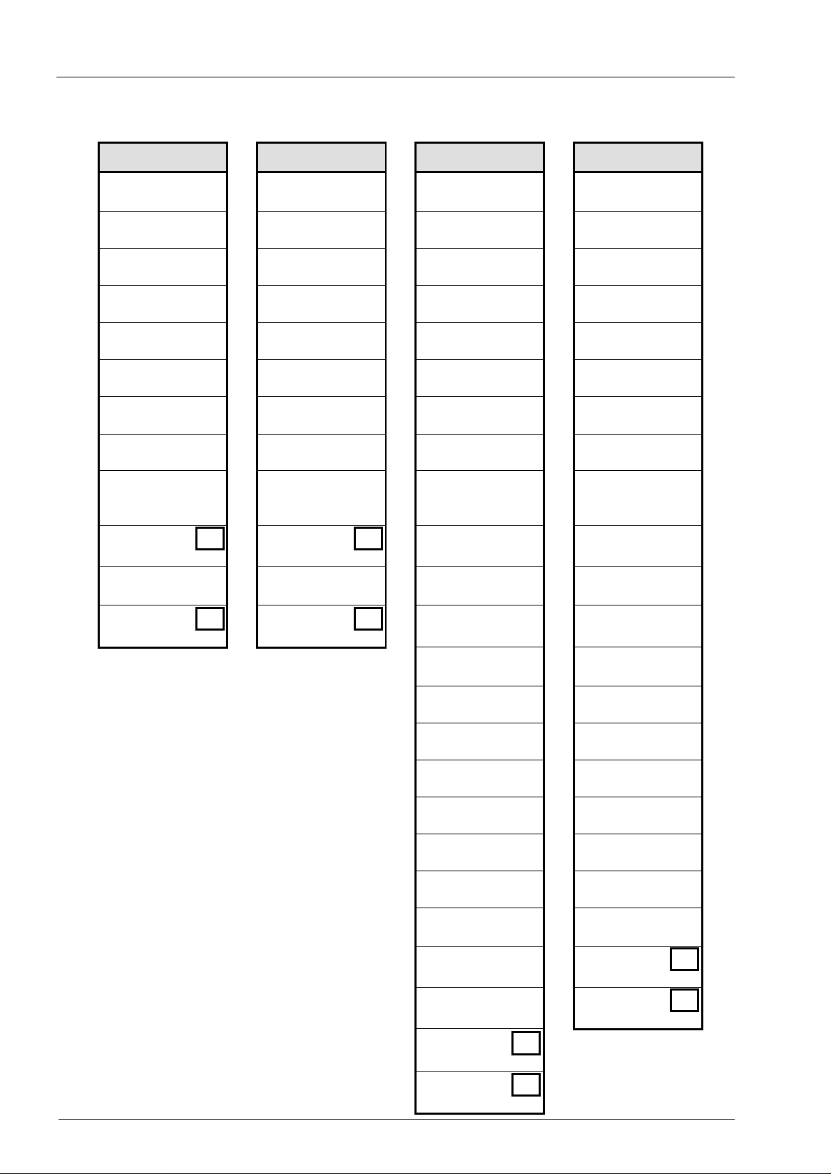
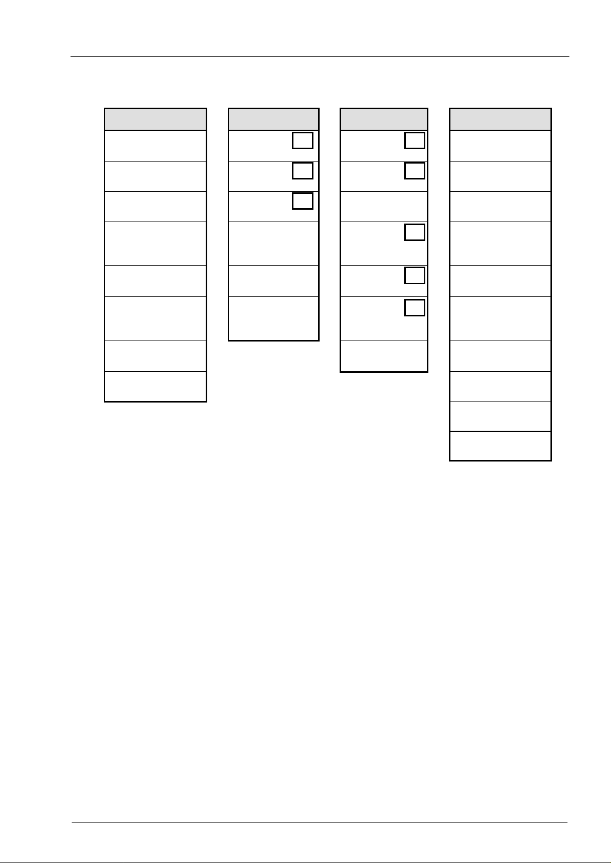
A summary of the standard main menu (list structure) is shown on the following pages. By
changing the value Menu (see page 87 ), a minimum main menu can be selected.
Elster GmbH 17
Volume Conversion Device EK260
↔
↔
Volume at base
conditions
To
"User"
↔
Flow at base cond. Actual flow Lower warn. limit Lower warn. limit
Disturbance quant. Disturbance quant. Upper warn. limit Upper warn. limit
Total quantity Total quantity Lower alarm limit Lower alarm limit
Adjustable counter Adjustable counter Upper alarm limit Upper alarm limit
Source monitoring Source monitoring Meas. range bottom Meas. range bottom
Upper warn. limit Upper warn. limit Meas. range top Meas. range top
Lower warn. limit Lower warn. limit Substitute value Substitute value
Meas. per. counter Meas. per. counter
Month's maximum Month's maximum Pressure mode Temperature mode
Daily counter Daily counter Press. sensor type Temp. sensor type
Month's maximum Month's maximum Sensor serial no. Sensor serial no.
Std.V.
Vb ↔ Vm ↔ p ↔ T
Vol. at base cond. Actual volume Pressure Temperature
Qb ↔ Qm
VbD ↔ VmD p.UW
VbT ↔ VmT pMin
VbA ↔ VmA pMax
SC.Qb ↔ SC.Q MRL.p
QbUW ↔ QmUW MRU.p
QbLW ↔ QmLW p.F
VbMP ∆
VbMP max S
VbDy ∆
VbDy max S
Equ. coefficient 1 Equ. coefficient 1
Equ. coefficient 2 Equ. coefficient 2
Equ. coefficient 3 Equ. coefficient 3
Actual volume
↔
Act.V.
VmMP ∆
VmMP max S
↔
VmDy ∆
VmDy max S
Eq1p
Eq2p
Eq3p Eq3T
p1Adj
Adjustment val. 1 Adjustment val. 1
p2Adj
Adjustment val. 2 Adjustment val. 2
Prog
Accept adjust. Accept adjust.
p.Amb
Air press. fixed val. Temp. meas.
p.Mes
Pressure meas. Meas. period mean
p.Abs
Abs.pressure meas. Month's maximum
Meas. period mean Month's minimum
Month's maximum
Month's minimum
Pressure
Press.
p.LW
Pb
Pressure at base
conditions
Md.p
Typ.p
SNp
p.MP ∅
p.Mon max S
p.Mon min S
Temperature
Temp.
T.LW
T.UW
TMin
TMax
MRL.T
MRU.T
T.F
Tb
Temp. at base
conditions
Md.T
Typ.T
SNT
Eq1T
Eq2T
T1Adj
T2Adj
Prog
T.Mes
T.MP ∅
T.Mon max S
T.Mon min S
To "Conv."
↔
18 Elster GmbH
Volume Conversion Device EK260
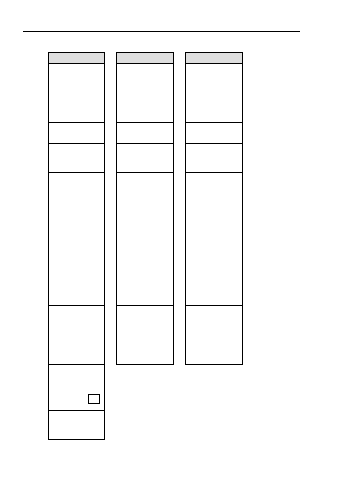
↔
↔
To
"Temp."
Conversion
Conv.
↔ C ↔
Conversion factor Month archive 1 Status register Date and time
K
Gas law dev. factor Month archive 2 Momentary status Daylight saving: y / n
Ho.b
Calorific value Meas. per. archive Clear S. Reg Meas. cycle time
CO2 MPer
(depends on Md.K) Rem. time mea. p. Audit Trail Disp. switch-off time
(depends on Md.K) ArMP frozen
K substitute value
K mode Ambient temp.
Software version
Software checksum
Carbon dioxide
content
H2 / N2 MP.Re
Rhob / dr FrMP
K.F
Md.K
Meas. period Logbook Operating cycle time
Archive Status + Logbook
Archiv
ArMo1 Arc
ArMo2 Arc
ArMP Arc
Clr MCyc
Status
SReg S
Stat S
Logb. Arc
AudTr Arc
PlogB Arc
Calibration Logb.
ClrPL SNo
clear Cal. Logb.
Ta.Rg
Vers
Chk
System
System
Time ↔
MdTim
OCyc
Disp
Aut.V
Disp. changeover
time
Serial number
To
"Serv."
Elster GmbH 19
Volume Conversion Device EK260
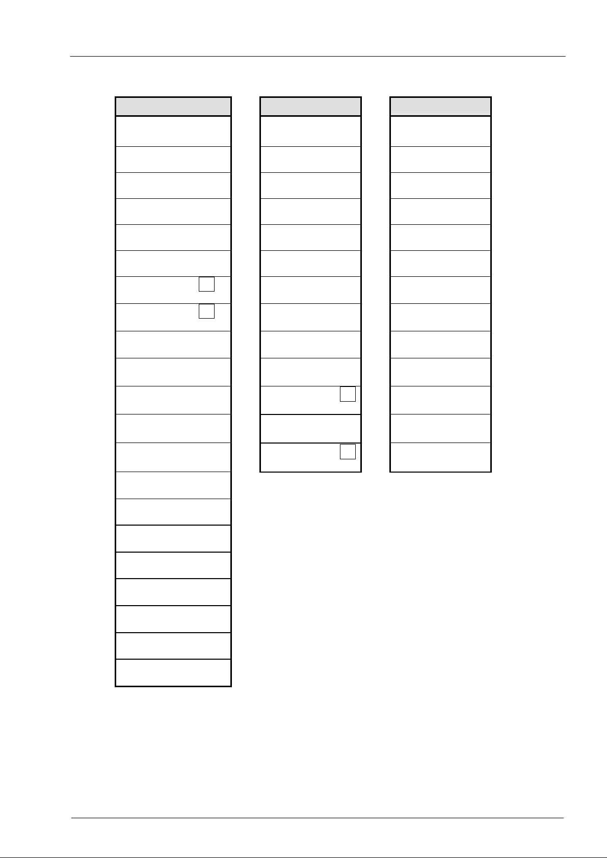
Service Inputs Outputs
To
"System"
Bat.R
↔
Remaining bat. life Orig. counter Input 1 Mode for Output 1
Bat.C cp.I1 SC.O1
Battery capacity Cp value Input 1 Source Output 1
Serv.
↔
Vo
Inputs
↔
Md.O1
Outp.
"Ser.IO."
↔
St.SL Md.I1 cp.O1
Supplier's lock Mode for Input 1 cp value Output 1
Cod.S V1 SpO1
Supplier's code Adj. counter Input 1 Status pointer O1
St.CL q.max Md.O2
Customer's lock
(only for encoder
mode)
Mode for Output 2
Cod.C cp.I2 SC.O2
Customer's code Cp value Input 2 Source Output 2
St.PL Md.I2 cp.O2
Calibration lock Mode for Input 2 cp value Output 2
Contr V2 SpO2
Display contrast Adj. counter Input 2 Status pointer O2
Adj.T St.I2 Aj1O2
Clock adjust. factor Status on Input 2 HF adjust factor 1
Sel.p MdMI2 Aj2O2
Select. press. sensor Mode monitorino I2 HF adjust factor 2
Save SC.I2 f1.O2
Save all data Source monitoring I2 Freq. for Aj1.O2
Clr.A L1.I2 f2.O2
Clear archives
Limit 1 for I2 Freq. for Aj2.O2
Clr.V L2.I2 Md.O3
Clear counters Limit 2 for I2 Mode for Output 3
Clr.X SpI2 SC.O3
Initialise device Stat. pointer mon. I2 Source Output 3
Bin.T St.I3 cp.O3
Temp. raw value Status on Input 3 cp value Output 3
Bin.p MdMI3 SpO3
Pressure raw value Mode monitoring I3 Status pointer O3
Addr SC.I3 Md.O4
User display address Source monitoring I3 Mode for Output 4
... L1.I3 SC.O4
User display Limit 1 für I3 Source Output 4
WRp SpI3 cp.O4
Repair counter W Stat. pointer mon. I3 cp value Output 4
VbRp SNM SpO4
Repair counter Vb Serial no. gas meter Status pointer O4
VmRp
Repair counter Vm
Rep.
Revision mode
ArCal Arc
Frozen values
Frz
Freeze
-
Display test
To
20 Elster GmbH
Volume Conversion Device EK260
Interfaces Energy User list
To
"Outp."
Md.S2
↔
Mode, Interface 2 Energy Vb total
DF.S2 P VmT
Data format, Interface 2 Power Vm total
Ser.IO
↔
W
Energ.
↔
VbT
User
Bd.S2 WD p
Baud rate, Interface 2 Disturbance quantity Pressure
TypS2 WT T
RS-232 / RS-485 Total quantity Temperature
Num.T WA K
No. of rings bef. answrg. Adjustable counter Gas law dev. factor
M.INI Ho,b C
Initialise modem Calorific value Conversion factor
PrLog S
Printer log Source monitoring Status register
CSync S
Clock set by rem. trans. Upper warning limit Month's maximum Vb
GSM.N
GSM network Lower warning limit Of month's max. Vb
GSM.L
Reception field strength Meas. per. counter Of month's max. Vb
StM
Modem status (GSM) Month's maximum Flow at base cond.
P.Sta
Response to PIN code Daily counter Actual flow
PIN
PIN code Month's maximum Display menu
Resp1
Response to Message 1
Response to Message 2
Send message
Baud rate, Interface 1
Call window 1 start
Call window 1 end
(depends on setting)
(depends on setting)
ANT2
SEND
Bd.S1
CW1.S
CW1.E
CW2.S / M.CW1
CW2.E / M.onl
SC.W
P.UW
P.LW
WMP ∆
WMP max S
WDy ∆
WDy max S
SReg
VbMP max
Date
Time
Qb
Qm
Menu
To
"Std.V."
↔
Elster GmbH 21

Volume Conversion Device EK260
3 Functional description
The data display is structured in tabular form (list structure) (→ 2.5). The individual
columns in the table each contain associated values. The following functional description
is orientated to this list structure.
Here, the following abbreviations are used:
- AD Abbreviated designation
Designation of the value in the display
- Access Write access
Indicates which lock must be opened to change the value (→ 2.4.1, 2.4.3):
- C = Calibration lock
- PL = Calibration logbook (PTB logbook, → page 42)
- M = Manufacturer's lock
- S = Supplier's lock
- K = Customer's lock
If the letter is located in brackets, the value can only be changed via the
interface and not via the keypad.
- Address Address of the value.
This is required especially for data transmission via the serial interface. The
address can be displayed by pressing the keys ← + → simultaneously.
- DC Data class
The data class shows, amongst other properties, whether and how the value
can be changed. (→ 2.3.1)
22 Elster GmbH

Volume Conversion Device EK260
3.1 Standard Volume (Volume at base conditions) list
AD Designation / value Unit Access Address DC
Vb Volume at base conditions m3 PL 2:300 12
Qb Flow at base conditions m3/h - 2:310 4
VbD Vb disturbed m3 S 2:301 12
VbT Vb total m3 - 2:302 15
VbA Vb adjustable m3 S 2:303 12
SC.Qb Source for warning Qb - S 7:154 8
QbUW Upper warning limit Qb m3/h K 7:158 8
QbLW Lower warning limit Qb m3/h K 7:150 8
VbMP ∆
Measurement period counter Vb m3 - 1:160 16
VbMP max Max. meas. per. count. Vb current month m3 - 3:160 16
VbDy ∆
Daily counter Vb m3 - 2:160 16
VbDy max Max. daily count. Vb current month m3 - 4:160 16
Vb Volume at base conditions
The Volume at base conditions computed from the measured "actual volume" is
summed here provided no alarm is present.
"Alarm" means "any message with the number "1" or "2" (→ 3.7 ).
Vb = Vm ž C where Vm = Actual volume (→ 3.2)
C = Conversion factor (→ 3.5)
Qb Flow at base conditions
Momentary flow at base conditions (standard flow rate).
Qb = Qm ž C with Qm = Actual flow (→ page 25)
C = Conversion factor (→ page 35)
The measurement inaccuracy of Qb is maximum 2% to 11% depending on the
boundary conditions quoted for Qm (→ page 25).
In the alarm state Qb is computed with the substitute values of the disturbed
measurements.
VbD Vb disturbed
Here the volume at base conditions is summed while ever an alarm is present, i.e.
a message with the number "1" or "2" is located in any momentary status (→ 3.7).
In the alarm state the volume at base conditions is computed with the substitute
values of the disturbed quantities. (→ 3.3: p.F, 3.4: T.F)
VbT Vb total
Here the sum of Vb + VbD is always displayed. Entries for Vb or VbD therefore
also have an effect here. No entry for VbT itself can be carried out.
VbA Vb adjustable
Here, as with VbT, the total quantity, i.e. disturbed and undisturbed volumes, are
counted. In contrast to VbT, VbA can however be changed manually.
The counter is typically used for tests.
Elster GmbH 23

Volume Conversion Device EK260
SC.Qb Source for Warning Qb
QbUW Upper warning limit Qb
QbLW Lower warning limit Qb
Using these three values, the flow at base conditions can be monitored in various
ways. When the value to be monitored exceeds the upper limit QbUW or falls
below the lower limit QbLW, the message "Vb Warn Lim." is entered in St.2 (→
page 47 ).
Various actions can in turn be programmed for this message, such as for example,
entry of the change of status in the logbook (→ 3.7) or activation of a signalling
output (→ 3.11).
With SC.Qb you can set which value is to be monitored.
SC.Qb Value to be monitored
0002:310_0 Qb Flow at base conditions
0001:160_0
0002:160_0
VbMP ∆ Meas. period counter Vb
VbDy ∆ Daily counter Vb
For further details on entering a source for SC.Qb: See Chap. 2.3.2.
VbMP ∆ Measurement period counter Vb
VbMP ∆ is restarted at "0" at the beginning of each measurement period (→ 3.6)
and indicates the progress of VbT (see above). The measurement period MPer
can be set in the archive list (→ 3.6).
At the end of each measurement period VbMP ∆ is saved in the measurement
period archive (→ 3.6).
VbMP ∆ can be monitored by appropriate programming of SC.Qb and QbUW (see
above) in order, for example, to issue a warning signal to a special-contract
customer when a limit is exceeded.
VbMP max Max. measurement period counter Vb in current month
By entering <ENTER> you can branch to the submenu where the time stamp of
the maximum is displayed.
The maxima of the last 15 months can be interrogated in the month archive 1
(→ 3.6).
VbDy ∆ Daily counter Vb
VbDy ∆ is restarted with "0" at the start of each day and indicates the progress of
VbT (see above). As standard, the start of day is set to 06:00 hrs. and can be
changed with the calibration lock open via the serial interfaces under the address
"2:141".
VbDy max Max. daily counter Vb in current month
By entering <ENTER> you can branch to the submenu where the time stamp of
the maximum is displayed.
The maxima of the last 15 months can be interrogated in the month archive 1
(→ 3.6).
24 Elster GmbH

Volume Conversion Device EK260
3.2 Actual volume (volume at measurement conditions) list
AD Designation / value Unit Access Address DC
Vm Actual volume m3 PL 4:300 12
Qm Actual flow rate m3/h - 4:310 4
VmD Vm disturbed m3 S 4:301 12
VmT Vm total m3 - 4:302 15
VmA Vm adjustable m3 S 4:303 12
SC.Q Source for Warning Q - S 8:154 8
QmUW Upper warning limit Qm m3/h K 8:158 8
QmLW Lower warning limit Qm m3/h K 8:150 8
VmMP ∆
Measurement period counter Vm m3 - 8:160 16
VmMP max Max. meas. per. count. Vm current month m3 - 10:160 16
VmDy ∆
Daily counter Vm m3 - 9:160 16
VmDy max Max. daily count. Vm current month m3 - 11:160 16
(Legends: see page 22)
Vm Actual volume
The volume V1 (→ 3.10) measured on the input is summed here provided no
alarm is present.
"Alarm" means "any message with the number "1" or "2" (→ 3.7 ).
The entry of Vm is not possible in the encoder mode (Md.I1 = 5). An attempt to
make an entry leads to entry error "11" (→ 2.3.3 )
In the encoder mode, to bring Vm to the gas meter reading and to clear VmD,
Md.I1 (→ 3.10 ) can first be set to "0" and then set again to "5".
Qm Actual flow rate
Momentary actual flow (actual flow rate).
The measurement inaccuracy of the displayed actual flow rate depends on
whether a pulse transmitter or an encoder is connected:
With a connected pulse transmitter:
With a pulse interval of a maximum of 15 minutes (at least four pulses per hour)
and cp.I1 ≤ 1 (→ page 58) the measurement uncertainty of Qm is maximum 1%.
With a pulse interval of more than 15 minutes Qm = "0" is displayed. After a
change of the gas flow the accurate value can only be shown once the gas meter
has sent at least two pulses.
With a connected encoder:
If the counter reading changes every 2 seconds or quicker, the measurement
uncertainty of Qm is maximum 1%.
With counter reading changes every 200 seconds or quicker the measurement
uncertainty is maximum 10%. It can be reduced down to 2% at MCyc = 4 seconds
by reducing the measuring cycle MCyc (→ page 51).
If the encoder counter reading does not change for longer than 200 seconds, Qm
= "0" is displayed.
Elster GmbH 25

Volume Conversion Device EK260
VmD Vm disturbed
Here the actual volume is summed while ever an alarm is present, i.e. a message
with the number "1" or "2" is located in any momentary status (→ 3.7).
The entry of VmD is not possible in the encoder mode (Md.I1 = 5). An attempt to
make an entry leads to entry error "11" (→ 2.3.3 )
In the encoder mode, to clear VmD and to bring Vm to the gas meter reading,
Md.I1 (→ 3.10 ) can first be set to "0" and then set again to "5".
VmT Vm total
Here the sum of Vm + VmD is always displayed. Entries for Vm or VmD therefore
also have an effect here. No entry for VmT itself can be carried out.
With the connection of an encoder (Md.I1 = 5, → 3.10), VmT corresponds with two
exceptions to the original counter Vo (→ 3.10 ) and so also to the gas meter
reading:
− When the gas meter runs backwards, VmT stops and only continues
synchronously with the gas meter again when the meter has a higher reading
than before it started to run backwards.
− VmT always has 9 pre-decimal and 4 post-decimal places, whereas the
encoder always has 8 significant places and has between 6 and 9 pre-decimal
places depending on the cp value of the gas meter. With a cp value of "1" VmT
has one pre-decimal place more which is incremented with each overflow of the
gas meter.
VmA Vm adjustable
Here, as with VmT, the total quantity, i.e. disturbed and undisturbed volumes are
counted. In contrast to VmT, VmA can however be changed manually.
This counter is typically set to the same reading as the gas meter in order to be
able to easily detect deviations by comparison of the two counter readings.
SC.Q Source for Warning Q
QmUW Upper warning limit Qm
QmLW Lower warning limit Qm
Using these three values, the actual flow can be monitored in various ways. When
the value to be monitored exceeds the upper limit Qm.UW or falls below the lower
limit Qm.LW, the message "Vm Warn Lim." is entered in St.4 (→ page 47 ).
Various actions can in turn be programmed for this message, such as for example,
entry of the change of status in the logbook (→ 3.6) or activation of a signalling
output (→ 3.11).
With SC.Q you can set which value is to be monitored.
SC.Q Value to be monitored
0004:310_0 Qm Actual flow rate
0008:160_0
0009:160_0
VmMP ∆ Measurement period counter Vm
VmDy ∆ Daily counter Vm
For further details on entering a source for SC.Q: See Chap.2.3.2.
26 Elster GmbH

Volume Conversion Device EK260
VmMP ∆ Measurement period counter Vm
VmMP ∆ is restarted with "0" at the beginning of each measurement period
(→ 3.6) and indicates the progress of VmT (see above). The measurement period
MPer can be set in the archive list (→ 3.6).
At the end of each measurement period VmMP ∆ is saved in the measurement
period archive (→ 3.6).
VmMP ∆ can be monitored by appropriate programming of SC.Qb and QbUW (see
above) in order, for example, to issue a warning signal to a special-contract
customer when a limit is exceeded.
VmMP max Max. measurement period counter Vm in current month
By entering <ENTER> you can branch to the submenu where the time stamp of
the maximum is displayed.
The maxima of the last 15 months can be interrogated in the monthly archive 1
(→ 3.6).
VmDy ∆ Daily counter Vm
VmDy ∆ is restarted with "0" at the beginning of each day and indicates the
progress of VmT (see above). As standard, the start of day is set to 06:00 hrs. and
can be changed if required via the serial interfaces under the address "2:141".
VmDy max Max. daily counter Vm in current month
By entering <ENTER> you can branch to the submenu where the time stamp of
the maximum is displayed.
The maxima of the last 15 months can be interrogated in the month archive 1
(→ 3.6).
Elster GmbH 27

Volume Conversion Device EK260
3.3 Pressure list
AD Designation / value Unit Access Address DC
p Pressure bar - 7:310_1 4
p.LW Lower warning limit pressure bar S 10:150 8
p.UW Upper warning limit pressure bar S 10:158 8
pMin Lower alarm limit pressure bar C 7:3A8_1 8
pMax Upper alarm limit pressure bar C 7:3A0_1 8
MRL.p Pressure meas. range lower limit bar C 6:224_1 8
MRU.p Pressure meas. range upper limit bar C 6:225_1 8
p.F Pressure substitute value bar S 7:311_1 8
pb Pressure at base conditions bar C 7:312_1 8
Md.p Pressure mode - C 7:317 7
Typ.p Pressure sensor type - C 6:223 8
SNp Serial no. of pressure sensor - C 6:222 8
Eq1p Coefficient 1 of pressure equation - C 6:280 8
Eq2p Coefficient 2 of pressure equation - C 6:281 8
Eq3p Coefficient 3 of pressure equation - C 6:282 8
p1Adj Adjustment value 1 for pressure bar C 6:260_1 8
p2Adj Adjustment value 2 for pressure bar C 6:261_1 8
Prog Accept pressure adjustment - C 6:259 2
p.Amb Air pressure fixed value bar C 6:212_1 8
p.Mes Pressure meas. bar - 6:211_1 4
p.Abs Absolute pressure measurement bar - 6:210_1 4
p.MP Ø Measurement period mean pressure bar - 19:160 16
p.Mon max Month's maximum pressure bar - 21:160 16
p.Mon min Month's minimum pressure bar - 22:160 16
(Legends: see page 22)
p Press.
p is the pressure which is used for computing the conversion factor (→ 3.5) and
hence the volume at base conditions (→ 3.1).
In disturbance-free operation the measurement p.Abs (see below) is used:
p = p.Abs.
With a relevant disturbance (alarm), the substitute value p.F (see below) is used:
p = p.F. In addition, disturbance quantities are then counted ( → 3.1, 3.2) and the
message "p Alarm Lim." displayed (→ page 45 ). Relevant disturbances are:
− p.Abs is located outside of the set limits pMin and pMax (see below).
− With a connected encoder (Md.I1 = 5, → 3.10) no actual volume can be
measured for more than 20 seconds. Since the gas flow variation is not known
for the time period and therefore no gas quantities can be assigned to the
measured values of pressure and temperature, the correction occurs as
disturbance quantities with substitute values for pressure and temperature.
(→ 4.5)
28 Elster GmbH

p.LW Lower warning limit pressure
p.UW Upper warning limit pressure
These values are used for monitoring the gas pressure p: When p exceeds the
upper limit p.UW or falls below the lower limit p.LW, the message "p Warn Lim." is
entered in St.7. (→page 47)
Various actions can in turn be programmed for this message, such as for example,
entry of the change of status in the logbook (→ 3.6) or activation of a signalling
output (→ 3.11).
pMin Lower alarm limit pressure
pMax Upper alarm limit pressure
The validity of the measured pressure p.Abs (see below) is checked based on
these alarm limits. This monitoring does not occur when pMin = pMax.
If p.Abs is located within the alarm limits, it is used as p (see below) for correction:
p = p.Abs.
If p.Abs is located outside the alarm limits, the substitute value p.F (see below) is
used: p = p.F. In addition, disturbance quantities are counted in this case (→ 3.1,
3.2) and the message "p Alarm Lim." is displayed. (→ page 45)
MRL.p Pressure meas. range lower limit
MRU.p Pressure meas. range upper limit
These details of the measurement range are used to identify the pressure sensor.
They have no effect on the measurements.
p.F Pressure substitute value
If the measured pressure p.Abs is outside the alarm limits pMin and pMax (see
below), p.F is used as pressure p for correction. p = p.F.
pb Pressure at base conditions
The pressure at base conditions is used for computing the conversion factor
(→ 3.5) and hence the volume at base conditions.
Md.p Pressure mode
With Md.p = "1" the measured pressure p.Abs (see below) is used for correction,
provided it does not violate the alarm limits.
With Md.p = "0" the fixed value (substitute value) p.F is always used for correction.
No disturbance quantities are counted.
Typ.p Pressure sensor type
Here the designation of the pressure sensor is displayed which was selected in the
service list with Sel.p. (→ 3.9).
SNp Serial no. of pressure sensor
Identification of the pressure sensor associated with the EK260.
Eq1p Coefficient 1 of pressure equation
Eq2p Coefficient 2 of pressure equation
Eq3p Coefficient 3 of pressure equation
The coefficients of the quadratic equation for calculating the pressure p.Mes from
the raw pressure value Bin.p (→ 3.9):
p.Mes = Eq1p + Eq2p ž Bin.p + Eq3p ž Bin.p2
To adjust the pressure measurement circuit, the three coefficients of the quadratic
equation can either be found by the EK260 itself after entry of Prog (see below) or
calculated and entered by the user.
The latter occurs based on three values for Bin.p and the corresp. set values.
Volume Conversion Device EK260
Elster GmbH 29

Volume Conversion Device EK260
The EK260 itself assumes a linear characteristic and after the entry of Prog (see
below) only determines the coefficients Eq1p and Eq2p. The third coefficient Eq3p
remains unchanged. The standard value for Eq3p is "0".
p1Adj Adjustment value 1 for pressure
p2Adj Adjustment value 2 for pressure
Prog Accept pressure adjustment
These values are used for the adjustment of the pressure measurement circuit, i.e.
for the internal computation of the equation coefficients for the pressure (see
above).
The adjustment takes place in three steps:
1. Apply measurement pressure 1 (= reference value 1) to the pressure sensor
and enter as p1Adj.
2. Apply measurement pressure 2 (= reference value 2) to the pressure sensor
and enter as p2Adj.
3. Enter Prog = "1" so that the EK260 calculates the equation coefficients.
After applying the measurement pressure, you should either wait about one minute
each time before entering the adjustment or press <ENTER> number of times
during the display of the pressure measurement p.Mes (see below) until the
displayed value is stable.
Approx. 0.4 ž pMax and approx. 0.9 ž pMax should be selected as adjustment
values.
p.Amb Air pressure fixed value
p.Mes Pressure measurement
p.Abs Absolute pressure measurement
p.Abs is the sum of p.Amb and p.Mes: p.Abs = p.Amb + p.Mes.
"0" should be entered when using an absolute pressure sentors and the ambient
pressure when using a gauge pressure sensor.
p.Mes is the absolute or gauge pressure depending on the pressure sensor.
If the measured pressure p.Abs is within the alarm limits pMin and pMax (see
above), then it is used as the pressure p for correction: p = p.Abs.
p.MP Ø Measurement period mean pressure
p.MP Ø is the averaged value of all pressure measurements within the current
measurement period.
At the end of each measurement period p.MP Ø is saved in the measurement
period archive (→ 3.6).
p.Mon max Month's maximum pressure
p.Mon min Month's minimum pressure
p.Mon max is the highest, p.Mon min the lowest of all pressure measurements
within the current month.
By entering <ENTER> you can branch to the relevant submenu where the
corresponding time stamp is displayed.
The maxima and minima of the last 15 months can be interrogated in the monthly
archive 2 (→ 3.6).
30 Elster GmbH

Volume Conversion Device EK260
3.4 Temperature list
AD Designation / value Unit Access Address DC
T Temperature °C - 6:310_1 4
T.LW Lower warning limit temperature °C S 9:150 8
T.UW Upper warning limit temperature °C S 9:158 8
TMin Lower alarm limit temperature °C C 6:3A8_1 8
TMax Upper alarm limit temperature °C C 6:3A0_1 8
MRL.T Temperature meas. range lower limit °C C 5:224_1 8
MRU.T Temperature meas. range upper limit °C C 5:225_1 8
T.F Temperature substitute value °C S 6:311_1 8
Tb Temperature at base conditions K C 6:312 8
Md.T Temperature mode - C 6:317 7
Typ.T Temp. sensor type - C 5:223 8
SNT Serial number of temperature sensor - C 5:222 8
Eq1T Coefficient 1 of temperature equation - C 5:280 8
Eq2T Coefficient 2 of temperature equation - C 5:281 8
Eq3T Coefficient 3 of temperature equation - C 5:282 8
T1Adj Adjustment value 1 for temperature °C C 5:260_1 8
T2Adj Adjustment value 2 for temperature °C C 5:261_1 8
Prog Accept temperature adjustment - C 5:259 2
T.Mes Temperature measurement °C - 5:210_1 4
T.MP Ø Measurement period mean temperature °C - 15:160 16
T.Mon max Month's maximum temperature °C - 17:160 16
T.Mon min Month's minimum temperature °C - 18:160 16
(Legends: see page 22)
T Temperature
T is the temperature which is used for computing the conversion factor (→ 3.5)
and hence the volume at base conditions (→ 3.1).
In disturbance-free operation the measurement T.Mes (see below) is used:
T = T.Mes.
With a relevant disturbance (alarm), the substitute value T.F (see below) is used:
T = T.F.
In addition, disturbance quantities are then counted ( → 3.1, 3.2) and the message
"T Alarm Lim." displayed (→ page 45 ). Relevant disturbances are:
− T.Mes is located outside of the set alarm limits TMin and TMax (see below).
− With a connected encoder (Md.I1 = 5, → 3.10) no actual volume can be
measured for more than 20 seconds. Since the gas flow variation is not known
for the time period and therefore no gas quantities can be assigned to the
measured values of pressure and temperature, the conversion occurs as
disturbance quantities with substitute values for pressure and temperature.
(→ 4.5)
Elster GmbH 31

Volume Conversion Device EK260
T.LW Lower warning limit temperature
T.UW Upper warning limit temperature
These values are used for monitoring the gas temperature T: When T exceeds the
upper limit T.UW or falls below the lower limit T.LW, the message "T Warn Lim." is
entered (→ page 47).
Various actions can in turn be programmed for this message, such as for example,
entry of the change of status in the logbook (→ 3.7) or activation of a signalling
output (→ 3.11).
TMin Lower alarm limit temperature
TMax Upper alarm limit temperature
The validity of the measured temperature T.Mes (see below) is checked, based on
these alarm limits. This monitoring does not occur when TMin = TMax.
If T.Mes is located within the alarm limits, it is used as T (see below) for
conversion: T = T.Mes.
If T.Mes is located outside the alarm limits, the substitute value T.F (see below) is
used: T = T.F. In addition, disturbance quantities are then counted (→ 3.1, 3.2)
and the message "T Alarm Lim." displayed (→ page 45 ).
MRL.T Temperature meas. range lower limit
MRU.T Temperature meas. range upper limit
These details of the measurement range are used to identify the temperature
sensor. They have no effect on the measurements.
T.F Temperature substitute value
If the measured temperature T.Mes is outside the alarm limits TMin and TMax
(see below), T.F is used as temperature T for conversion. T = T.F.
Tb Temperature at base conditions
The temperature at base conditions is used for computing the conversion factor
(→ 3.5) and hence the volume at base conditions.
Md.T Temperature mode
With Md.T = "1" the measured temperature T.Mes (see below) is used for
conversion, provided it does not violate the alarm limits.
With Md.T = "0" the fixed value (substitute value) T.F is always used for
conversion. No disturbance quantities are counted.
Typ.T Temperature sensor type
SNT Serial number of temperature sensor
Identification of the temperature sensor associated with the EK260.
Eq1T Coefficient 1 of temperature equation
Eq2T Coefficient 2 of temperature equation
Eq3T Coefficient 3 of temperature equation
The coefficients of the quadratic equation for calculating the temperature T.Mes
from the raw temperature value Bin.T (→ 3.9):
T.Mes = Eq1T + Eq2T ž Bin.T + Eq3T ž Bin.T2
To adjust the temperature measurement circuit, the three coefficients of the
quadratic equation can either be found by the EK260 itself after entry of Prog (see
below) or calculated and entered by the user.
The latter occurs based on three values for Bin.T and the corresp. set values.
32 Elster GmbH

The EK260 itself assumes a linear characteristic and after the entry of Prog (see
below) only determines the coefficients Eq1T and Eq2T. The third coefficient Eq3p
remains unchanged. The standard value for Eq3T is 6.411ž10-8.
T1Adj Adjustment value 1 for temperature
T2Adj Adjustment value 2 for temperature
Prog Accept temperature adjustment
These values are used for the adjustment of the temperature measurement circuit,
i.e. for the internal computation of the equation coefficients for the temperature
(see above).
The adjustment takes place in three steps:
1. Apply measurement temperature 1 (= reference value 1) on the temperature
sensor and enter as T1Adj.
2. Apply measurement temperature 2 (= reference value 2) on the temperature
sensor and enter as T2Adj.
3. Enter Prog = "1" so that the EK260 calculates the equation coefficients.
After applying the measurement temperature, you should either wait about one
minute each time before entering the adjustment or press <ENTER> a number of
times during the display of the temperature measurement T.Mes (see below) until
the displayed value is stable.
To optimise the accuracy, the adjustment values should be located as close as
possible to the measurement range limits MRL.T and MRU.T (e.g. -10°C and
+60°C).
T.Mes Temperature measurement
If the measured temperature T.Mes is within the alarm limits TMin and TMax (see
below), then it is used as the temperature T (see above) for conversion.
T = T.Mes.
T.MP Ø Measurement period mean temperature
T.MP is the averaged value of all temperature measurements within the current
measurement period.
At the end of each measurement period T.MP Ø is saved in the measurement
period archive (→ 3.6).
T.Mon max Month's maximum temperature
T.Mon min Month's minimum temperature
T.Mon max is the highest, T.Mon min the lowest of all temperature measurements
within the current month.
By entering <ENTER> you can branch to the relevant submenu where the
corresponding time stamp is displayed.
The maxima and minima of the last 15 months can be interrogated in the monthly
archive 2 (→ 3.6).
Volume Conversion Device EK260
Elster GmbH 33

Volume Conversion Device EK260
3.5 Volume corrector list
Which values are displayed in this list depends on the set K-value and the computation
mode Md.K (see below):
a) Computation according to S-Gerg-88 (Md.K = 1)
AD Designation / value Unit Access Address DC
C Conversion factor - - 5:310 4
K Inverted compressibility factor ratio - - 8:310 4
pbX Pressure at base conditions for gas analysis bar S 7:314_1 8
TbX Temperature at base cond. for gas analysis °C S 6:314_1 8
Ho.b Calorific value kWh/m3 S 10:312_1 8
CO2 Carbon dioxide content % S 11:311 8
H2 Hydrogen content % S 12:311 8
Rhob Density gas at base conditions kg/m3 S 13:312_1 8
K.F K-value substitute value - S 8:311 8
Md.K K-value mode - C 8:317 7
b) Computation according to AGA-NX19 (Md.K = 2)
AD Designation / value Unit Access Address DC
C Conversion factor - - 5:310 4
K Inverted compressibility factor ratio - - 8:310 4
pbX Pressure at base conditions for gas analysis bar S 7:314_1 8
TbX Temperature at base cond. for gas analysis °C S 6:314_1 8
Ho.b Calorific value kWh/m3 S 10:311_1 8
CO2 Carbon dioxide content % S 11:311 8
N2 Nitrogen content % S 14:311 8
dr Density ratio - S 15:311 8
K.F K-value substitute value - S 8:311 8
Md.K K-value mode - C 8:317 7
c) Computation according to AGA-8 Gross Characterisation Method 1 (Md.K = 3)
AD Designation / value Unit Access Address DC
C Conversion factor - - 5:310 4
K Inverted compressibility factor ratio - - 8:310 4
pbX Pressure at base cond. for gas analysis bar S 7:314_1 8
TbX Temperature at base cond. for gas analysis °C S 6:314_1 8
Ho.b Calorific value kWh/m3 S 10:314_1 8
CO2 Carbon dioxide content % S 11:314 8
dr Density ratio - S 15:314 8
K.F K-value substitute value - S 8:311 8
Md.K K-value mode - C 8:317 7
34 Elster GmbH

Volume Conversion Device EK260
d) Computation according to AGA-8 Gross Characterisation Method 2 (Md.K = 4)
AD Designation / value Unit Access Address DC
C Conversion factor - - 5:310 4
K Inverted compressibility factor ratio - - 8:310 4
CO2 Carbon dioxide content % S 11:314 8
N2 Stickstoff-Anteil % S 14:314 8
dr Density ratio - S 15:314 8
K.F K-value substitute value - S 8:311 8
Md.K K-value mode - C 8:317 7
e) Computation according to AGA-NX19 following Herning & Wolowsky (Md.K = 5)
AD Designation / value Unit Access Address DC
C Conversion factor - - 5:310 4
K Inverted compressibility factor ratio - - 8:310 4
CO2 Carbon dioxide content % S 11:314 8
N2 Nitrogen content % S 14:314 8
dr Density ratio - S 15:314 8
K.F K-value substitute value - S 8:311 8
Md.K K-value mode - C 8:317 7
f) Constant K value (Md.K = 0)
AD Designation / value Unit Access Address DC
C Conversion factor - - 5:310 4
Ho.b Calorific value kWh/m3 S 10:311_1 8
K.F K-value substitute value - S 8:311 8
Md.K K-value mode - C 8:317 7
(Legends: see page 22)
The rated operating conditions applying to the various conversion methods are described
in Chapter 4.1.
C Conversion factor
The conversion factor is calculated according to the following formula:
Tb
p
1
C ⋅⋅=
pb
K
T
(p, pb: → 3.3, T, Tb → 3.4, K: see below)
Elster GmbH 35

Volume Conversion Device EK260
Z
K Inverted compressibility factor ratio (K-value)
The inverted compressibility factor ratio is used for computing the conversion
factor (see above). It is calculated according to the following formula:
Z
K =
b
where Z = compressibility factor and Zb = compressibility factor at reference
conditions.
The computation of Z and Zb occurs according to S-Gerg-88 or AGA-NX19
depending on the setting of Md.K. The gas analysis values Ho.b, CO2, H2 and
Rhob (Md.K = 1) or N2 and dr (Md.K = 2) need to be included in the entries for this
(see below).
If the K-value mode Md.K (see below) is set to "fixed value" (= "0"), K is not
computed, but the substitute value K.F (see below) is used instead.
pbX Pressure at base conditions for the gas analysis
TbX Temperature at base conditions for the gas analysis
The standard states described by pbX and TbX apply to the entry of the gas
analysis Ho.b, CO2 ... dv (see below). In contrast to this the conversion factor C
(see above and the volume at base conditions Vb (→ 3.1 ) are calculated
according to pb and Tb (→ 0 and 3.4 ).
With each change of pb or Tb, pbX resp. TbX is automatically set to the same
value. For different values pbX or TbX must be entered after pb resp. Tb.
Ho.b Calorific value
CO2 Carbon dioxide content
H2 Hydrogen content (only for Md.K = 1)
Rhob Density gas at base conditions (only for Md.K = 1)
N2 Nitrogen content (only for Md.K = 2)
dr Density ratio (only for Md.K = 2)
Depending on the set K-value mode Md.K, these gas analysis values must be
entered so that the inverted compressibility factor ratio K can be correctly
computed.
For calculations according to S-Gerg-88 (Md.K = 1) and/or AGA-NX19 (Md.K = 2)
the valid ranges are:
Ho.b 6.0 ...13.0 kWh/m3
CO2 0.0 ...30.0 Mol-%
H2 0.0 ...10.0 Mol-%
Rhob 0.71 ...1.16 kg/m3
N2 0.0 ...30.0 Mol-%
dr 0.554 ...0.900 for "L gas" (Ho.b ≤ 11.055)
0.554 ...0.691 for "H gas" (Ho.b > 11.055)
F Furthermore, the following limits must be ensured by the gas supplier:
Methane CH4 50 - 100 % Propane C3H8 0 - 5 %
Nitrogen N2 0 - 50 % Butane C4H10 0 - 1 %
K.F K-value substitute value
36 Elster GmbH
Ethane C2H6 0 - 20 % Pentane C5H12 0 – 0.5 %
If the K-value mode Md.K (see below) is set to "fixed value" (= "0"), the constant
substitute value K.F is used instead of the calculated inverted compressibility
factor ratio K for the computation of the conversion factor C (see above).

Volume Conversion Device EK260
Md.K K-value mode
With Md.K you can set whether the conversion factor C (→ 3.5) and hence the
volume at base conditions Vb (→ 3.1) are determined with the calculated K-value
or with the constant K-value, K.F:
Md.K = "0": The fixed value (substitute value) K.F is used.
Md.K = "1": The K-value is calculated according to S-Gerg-88.
Md.K = "2": The K-value is calculated according to AGA-NX19.
Md.K = "3": The K-value is calculated according to the AGA-8 Gross
characterisation method 1.
Md.K = "4": The K-value is calculated according to the AGA-8 Gross
characterisation method 2.
Md.K = "5": The K-value is calculated according to AGA-NX19 following Herning &
Wolowsky.
3.6 Archive list
AD Designation / value Unit Access Address DC
ArMo1 Monthly archive 1 - - 1:A30 8
ArMo2 Monthly archive 2 - - 2:A30 8
ArMP Measurement period archive - - 3:A30 8
MPer Measurement period Minutes PL 4:150 8
MP.Re Remaining time of measurement period Minutes - 4:15A 15
FrMP Freeze measurement period - S 3:A50 2
(Legends: see page 22)
ArMo1 Monthly archive 1
Entry point for the first monthly archive in which counter readings and consumption
maxima from the last 15 months are saved.
The day boundary (= month boundary ) "06:00 hrs." can be changed via the serial
interfaces under the address 2:141.
"Check"
Each archive data row has the following entries:
↔ ABNo
Block
To
number
VbDy max Time Stat Vm VmT
↔
Month's
maximum
Stat
↔
Status for
VmMP max
Time Vb VbT VbMP max Time Stat ↔
Storage time
Time-point
VbDy max
VmDy
max
Month's
maximum
Volume at
base cond.
Status for
VbDy max
Time Stat St.2 St.4 Check
Time-point
VmDy max
Totaliser
Vb
Actual
volume
Status for
VmDy max
Month's
maximum
Totaliser Vm
Status 2
(incl. Vb)
Time-point
VbMP max
VmMP
max
Month's
maximum
Status 4
(incl. Vm)
Status for
VbMP max
Time
Time-point
VmMP max
Checksum
↔
↔
To
"ABNo"
Elster GmbH 37

Volume Conversion Device EK260
To
ArMo2 Monthly archive 2
Entry point for the second monthly archive in which maxima, minima and some
mean values for Qb, Qm, p, T from the last 15 months are saved.
The day boundary (= month boundary ) "06:00 hrs." can be changed via the serial
interfaces under the address "2:141".
"Check"
Each archive data row has the following entries:
↔ ABNo
Block
To
number
Time ↔
Storage time
↔ Qb max Time Stat Qb min Time Stat ↔
Month's
maximum
Time-point
Qb max
Status for
Qb max
Month's
minimum
Time-point
Qb min
Status for
Qb min
↔ Qm max Time Stat Qm min Time Stat ↔
Month's
maximum
Time-point
Qm max
Status for
Qm max
Month's
minimum
Time-point
Qm min
Status for
Qm min
↔ p.Mon Ø p.Mon max Time Stat p.Mon min Time Stat ↔
Pressure
mean
Month's
maximum
Time-point
p max
Status for
p max
Month's
minimum
Time-point
p min
Status for
p min
↔ T.Mon Ø T.Mon max Time Stat T.Mon min Time Stat ↔
Temperature
mean
Month's
maximum
Time-point
T max
Status for
T max
Month's
minimum
Time-point
T min
Status for
T min
↔ K.Mon Ø C.Mon Ø St.7 St.6 St.8 St.5 Check ↔
K-value
mean
C factor mean
Status 7
(incl. p)
Status 6
(incl. T)
Status 8
(incl. K)
Status 5
(incl. C)
Checksum
ArMP Measurement period archive
Entry point for the measurement period archive where counter readings and
measurements are archived in the cycle of the measurement period MPer. The
archive has approx. 7000 data rows, corresponding to a memory depth of about 9
months for a measurement period of 60 minutes.
Each archive data row has the following entries:
↔ ABNo
Block
"Check"
↔
number
∆ Vm
Time Vb
Storage
time
VmT
Volume at
base cond.
∆ VmT
∆ Vb
Counter
increment
VbT
Totaliser
Vb
∆ VbT
Counter
increment
Vm ↔
Actual
volume
p.MP Ø T.MP Ø K.MP Ø C.MP Ø ↔
To
"ABNo"
To
"ABNo"
To
"ABNo"
Counter
increment
↔ St.2 St.4 St.7 St.6 StSy Ev Check
Status 2
(incl. Vb)
Totaliser
Vm
Status 4
(incl. Vm)
Counter
increment
Status 7
(incl. p)
Pressure
mean
Status 6
(incl. T)
Temperatur
e mean
System
status
K-value
mean
Trigger
event
C factor
mean
Checksum
↔
To
"ABNo"
38 Elster GmbH

The totalizer increments in comparison to the corresponding previous entry are
identified with a "∆". They are only shown in the display and are not read out over
the interface.
Normally, the flow (consumption) within a measurement period is involved here.
This does not occur when an archive row has been entered due to a special event
(e.g. setting of the clock or of a counter, appearance of an important status
message). Then the segment "∆" and the abbreviated designation flash for the
displayed counter increment in order to make the user aware of this special
feature.
With the calibration lock open and with the aid of the "WinPADS" parameterisation
software, it is possible to set which counters and associated counter increments
are saved in this archive:
Standard setting
Meaning Address Value Meaning
1st counter in the archive 3:0C00 2:0300 Vb
2nd counter in the archive 3:0C01 2:0302 VbT
3rd counter in the archive 3:0C02 4:0300 Vm
4th counter in the archive 3:0C03 4:0302 VmT
MPer Measurement period
With the measurement period that can be set here, all values related to the
measurement period are formed. These are: VbMP ∆ (→ 3.1), VmMP ∆ (→ 3.2),
p.MP Ø (→ 3.3) , T.MP Ø (→ 3.4) as well as values present in the measurement
period archive ArMP (see above).
MPer must be an integer multiple of the operating cycle OCyc (→ 3.8) so that the
measurement period values (e.g. VbMP ∆, VbDy ∆ , p.MP ∅, T.MP ∅) can be
concluded at the correct points in time.
With the default setting for OCyc the following values for MPer are practicable and
usual: 5, 10, 15, 20, 30 or 60 minutes.
MP.Re Remaining time of measurement period
Display of remaining time for the current measurement period for the user's
information. The output is given right-justified in minutes.
FrMP Measurement period archive, freeze
A data row can be saved in the measurement period archive ArMP (see above)
with this function. Based on the "trigger event" Er which is also saved, it can be
seen in the data row whether it was saved automatically due to the expired
measurement period or by triggering of FrMP.
Volume Conversion Device EK260
Elster GmbH 39

Volume Conversion Device EK260
3.6.1 Device numbers and channel numbers for WinView and WinLIS
The contents of the archives described here are suitable for processing with the WinLIS
and WinVIEW evaluation programs. The data is allocated there to so-called "device
numbers" (DS-100 numbers). Within each "device number" the so-called "channel
number", indicating the type of data, is located at the fifth position from the right (ten
thousands position).
Channel
number
Value
1 Vb Volume at base conditions (undisturbed)
2 VbT Total volume at base conditions
3 Vm Actual volume (undisturbed)
4
VmT
Vo
For pulse counting: Total actual volume
In the encoder mode: Actual reading of the encoder counter
5 C Conversion factor
6 T Gas temperature
7 p Gas pressure
8 K K-value
Examples:
• Device number: 1438004 ⇒ Channel number = 3 ⇒ Vm (Actual volume
undisturbed)
• Device number: 1479321 ⇒ Channel number = 7 ⇒ p (Gas pressure)
3.6.2 Find function for checking the archive entries
The measurement period archive comprises many thousands of entries. The device has a
Find function for archive entries in order to be able to display single values from this
quantity of data for checking purposes. Values can be sought in the following columns:
• Block number
• Date and time
• Counter readings
The search takes place initially by selecting the desired column (block number, date/time
or counter reading) in any archive row. Once the "ENTER" key has been pressed, the
value to be found in this column can be entered. After termination of the entry with
<ENTER>, the display skips to the archive row with the entered value. If it is not present,
the display skips to the entry which is closest to the one sought.
40 Elster GmbH

Volume Conversion Device EK260
3.7 Status list
AD Designation / value Unit Access Address DC
SReg Status register, total - - 1:101 19
Stat Momentary register, total - - 1:100 5
Clr Clear status register - S 4:130 2
Logb. Logbook - - 4:A30 8
AudTr Audit Trail - - 5:A30 8
PLogB Calibration logbook (PTB logbook) - - 9:A30 8
ClrPL Clear calibration logbook - C 9:A52 2
(Legends: see page 22)
SReg Status register, total
Stat Momentary register, total
The EK260 supplies two types of status information: Momentary status (also
known as "status") and the status register.
- Messages in the momentary status point to current statuses such as for example,
errors that are present. When the condition is no longer present, the corresponding
message in the momentary status disappears. Manual deletion is not possible.
Alarms, warnings and reports (i.e. messages with numbers in the range from "1" to
"16") are displayed in the momentary statuses.
- In the status register all messages since the last manual clearing are collected.
Here, you can also see what has happened, for example, since the last station
inspection. The messages can be cleared in this list with the command "Clr".
Only alarms and warnings (i.e. messages with numbers in the range from "1" to
"8") are displayed in status registers. Reports are not entered because they
identify states which are not problematical or may even be intended (e.g. "Daylight
saving time", "Calibration lock open" or "Data transfer running").
SReg and Stat initially show all existing messages as numbers.
They can be recalled individually as short text by pressing <ENTER>: First, the
most important message (with the lowest number) is displayed. You can switch to
the next or previous message with the keys → and ← respectively.
An overview of the possible messages and their meanings is given in Chapter (→
3.7.1 page 44).
The display also shows the short text
- in the upper row to the right of the associated status register name and
- in the lower row to the left of the message number (prefixed with "#").
You need the status register name and the message name, for example for
entering a "status pointer" for the outputs (SpO1, SpO2, etc. → 3.11, page 64).
All the status messages are list in Chapter 3.7.1 (from page 44 onwards).
Deleting messages:
After entering <
(acknowledged) singly by pressing the key combination ← + ↑ . With the
command Clr (see below) all messages in "SReg" can be cleared simultaneously.
ENTER
> the messages in SReg (not in Stat) can be cleared
Elster GmbH 41

Volume Conversion Device EK260
To
"Check"
To
"Check"
Calibration
turer's
Clr Clear status register
This enables you to clear all the status register contents, i.e. "SReg" and its
complete submenu: After calling by ENTER, an "0" is positioned right-justified in
the display. The function is triggered, i.e. all status registers are cleared, after
switching to "1" (with ↑) and terminating with ENTER.
If the alarm or warning states are however still present, they are again directly
entered as messages.
The messages in SReg can also be cleared singly: see above under SReg.
Logb. Logbook (event logbook)
Entry addresses for the logbook in which the last 250 status changes are archived.
Each archive data row has the following entries:
ABNo
↔
Block number Storage time-point Trigger event Checksum
Time Ev Check
↔
To
"ABNo"
AudTr Audit trail (changes logbook )
Entry addresses for the changes logbook (audit trail) in which the last 200 settings
changes (parameterisations) are archived.
Each archive data row has the following entries:
↔
ABNo
Block
number
Time Addr a n
Storage timepoint
Address of
changed value
St.PL St.ML St.SL St.CL Check
↔
lock
Manufac
lock
Supplier's lock
PLogB Calibration logbook (PTB logbook)
With the aid of the "Calibration logbook" according to PTB-A 50.7 some
parameters relevant to calibration regulations can be changed also with the
calibration lock closed. Prerequisites for this are:
- The supplier's lock (see below) must be open.
- At least three free entries must be available in the calibration logbook.
The affected parameters (e.g. cp value, measurement period) are identified with
the access right "PL" in the lists in this capital.
For each change of such a parameter with the calibration lock closed a data row is
in each case entered with the value before and after the change. Additionally, an
entry is always made on opening and closing the calibration lock.
Old value New value
Customer's
lock
Checksum
↔
↔
To
"ABNo"
42 Elster GmbH
The calibration logbook has 50 data rows. Since the first data row always logs the
closure of the calibration lock and the last data row is always kept free for opening
the calibration lock, a maximum of 48 parameter changes can be entered. With a
logbook which is fully written up the status message "PLogb full "is displayed in
the system status (→ page 48 ) and "L" (→ page 11 ) flashes in the display field
"Status". The calibration logbook can be cleared with the calibration lock open
using the command ClrPL (see below).
F If the calibration lock is opened with the calibration logbook full, it can only be
closed again after clearing the calibration logbook.
The data rows of the calibration logbook have the following entries:

Volume Conversion Device EK260
↔
"Check"
to
Block
number
ABNo
Time
Storage time Addr. of
Add a n
Old value New value
changed value
↔
↔
St.PL St.ML
Calibration
lock
Manufacturer's
lock
ClrPL Clear calibration logbook
The calibration logbook PlogB can be cleared by entering "1" with the calibration
lock open.
St.SL St.CL Check
Supplier's lock Customer's
lock
Checksum
↔
To
"ABNo"
Elster GmbH 43

Volume Conversion Device EK260
1
Vm Warn Lim.
2
3
3.7.1 List of status messages
Message
Alarm
Warning
Report
in status AD Description
1 StSy SRSy Restart Restart of the device
1 St.5 SR.5 C-fact. err. Conversion factor cannot be computed
1 St.6 SR.6 T Alarm Lim. Alarm limits for temperature violated
1 St.7 SR.7 p Alarm Lim. Alarm limits for pressure violated
1 St.8 SR.8 K-val. error Compressibility cannot be computed
1 St.9 SR.9 Z-fact. err. Compressibility factor cannot be computed
2 St.1 SR.1 I1 Alarm Alarm on Input I1
2 St.5 SR.5 T Inp. Error No usable input value for temperature
2 St.6 SR.6 p Inp. error No usable input values for pressure
3 StSy SRSy Data restore Data has been restored
4 St.1 SR.1 Outp.1 Error Error on Output 1
4 St.2 SR.2 Outp.2 error Error on Output 2
4 St.3 SR.3 Outp.3 error Error on Output 3
4 St.4 SR.4 Outp.4 error Error on Output 4
5 St.2 SR.2 I2 Pulse cmp Error during pulse comparison on Input 2
6 St.1 SR.1 W Warn Lim. Warning limits for power violated
6 St.2 SR.2 Vb Warn Lim. Warning limits for flow at base cond. violated
6 St.4 SR.4
Warning limits for actual flow violated
6 St.6 SR.6 T Warn Lim. Warning limits for temperature violated
6 St.7 SR.7 p Warn Lim. Warning limits for pressure violated
7 StSy SRSy Soft. error Software error
8 StSy SRSy Sett. error Setting error
8 St.2 SR.2 I2 Warn.sig. Warning signal on Input I2
8 St.3 SR.3 I3 Warn.sig. Warning signal on Input I3
9 StSy . Batt. low Battery service life below limit
10 StSy . Repair mode Repair mode switched on
11 StSy . Clock n. set Clock not set
11 St.1 . Encoder err. Encoder error
12 StSy . PLogb full Calibration logbook full
13 StSy . online Data transmission running
13 St.2 . I2 Rep.sig. Report signal on Input I2
13 St.3 . I3 Rep.sig. Report signal on Input I3
14 StSy . Remote clock Remote clock setting started
14 St.1 . Cal.lock o. Calibration lock open
14 St.2 . Man.lock o. Manufacturer's lock is open
14 St.3 . Supp.lock o. Supplier's lock is open
14 St.4 . Cust.lock o. Customer's lock is open
15 StSy . Batt. operat Battery operation
15 St.1 . Call Win.1+ Extended Call acceptance time window 1
16 StSy . Dayl.Sav.Tim The displayed time is daylight saving time
16 St.1 . Call Win.1 Call acceptance time window 1 is activ e
16 St.2 . Call Win.2 Call acceptance time window 2 is active
1
Alarm: Instead of the act. measurement, the substitute value is used; quantities are
counted in the disturbance volume counter.
2
Warning: The message is held in the status register until manually deleted.
3
Report: The message is not kept in the status register.
44 Elster GmbH

Volume Conversion Device EK260
Restart Restart of the device Message 1 in StSy
The device was started without usable data. Counter readings and archives are
empty, the clock has not been set.
C-fact. err. Conversion factor cannot be computed Message 1 in St.5
The conversion factor C (→ 3.5) cannot be computed because the temperature T
(→ 3.4) is outside the range -100°C to +100°C or no usable inverted compressibility
factor ratio K (→ 3.5) is available (cf. message “1” in “St.8”). Possibly the temperature
sensor is not connected correctly or the substitute value for the inverted
compressibility factor ratio K.F (→ 3.5) has the value "0".
The conversion factor is set to "0" and disturbance quantities for Vb are counted in
VbD (→ 3.1).
With the correct device setting, this message does not occur, because, for example,
when an alarm limit, TMin or TMax (→ 3.4), is exceeded, the temperature substitute
value T.F is used.
T Alarm Lim. Alarm limits for temperature violated Message 1 in St.6
The measured gas temperature T.Mes is located outside of the set alarm limits TMin,
TMax (→ 3.4).
While ever this message is present in St.6, the substitute temperature T.F (→ 3.4) is
used for volume conversion and disturbance quantities are counted for Vb and Vm
(→ 3.1, 3.2).
The alarm limits can be changed with the calibration lock open. If they are set to the
same value, they are ignored, i.e. they cannot cause any alarm messages nor
disturbance quantities.
p Alarm Lim. Alarm limits for pressure violated Message 1 in St.7
The measured gas pressure p.Abs is located outside of the set alarm limits pMin,
pMax (→ 3.3).
While ever this message is present in St.7, the substitute pressure p.F (→ 3.3) is
used for volume conversion and disturbance quantities are counted for Vb and Vm
(→ 3.1, 3.2).
The alarm limits can be changed with the calibration lock open. If they are set to the
same value, they are ignored, i.e. they cannot cause any alarm messages nor
disturbance quantities.
K-val. error Compressibility cannot be computed Message 1 in St.8
The inverted compressibility factor ratio K (→ 3.5) cannot be computed because no
valid compressibility factor could be determined. (see below: "Z-fact. err.")
While ever this problem exists, the substitute value K.F is used for the inverted
compressibility factor ratio and disturbance quantities are counted for Vb and Vm
(→ 3.1, 3.2).
Z-fact. err. Compressibility factor cannot be computed Message 1 in St.9
At least one of the gas analysis values Ho.b, CO2, H2, Rhob (→ 3.5) is located
outside of the permissible range.
While ever this problem exists, the last valid value for each of the affected gas
analysis values is used and disturbance quantities are counted for Vb and Vm
(→ 3.1, 3.2). If a valid value has not yet been able to be calculated (because the gas
analysis has not till now been correct), the compressibility factor is set to "0".
Consequently therefore, also no inverted compressibility factor ratio can be
computed. (See above: Message "1” in St.8).
Elster GmbH 45

Volume Conversion Device EK260
I1 Alarm Alarm on Input I1 Message 2 in St.1
With a connected encoder (Md.I1 = 5, → 3.10) no actual volume could be measured
for more than 20 seconds (→ 4.5). Possible causes are, for example, a cable
breakage or low batteries in the EK260.
In this case the substitute values p.F (→ 3.3) and T.F (→ 3.4) are used for volume
conversion and disturbance quantities are counted for Vb and Vm (→ 3.1, 3.2 ).
T Inp. Error No usable input value for temperature Message 2 in St.5
The signal, Bin.T (→ 3.9), measured on the temperature input is outside the valid
range. The sensor may not be correctly connected.
In this case the substitute temperature T.F (→ 3.4) is used for volume conversion and
disturbance quantities are counted for Vb and Vm (→ 3.1, 3.2).
p Inp. error No usable input values for pressure Message 2 in St.6
The signal, Bin.p (→ 3.9), measured on the pressure input is outside the valid range.
The sensor may not be correctly connected.
In this case the substitute pressure p.F (→ 3.3) is used for volume conversion and
disturbance quantities are counted for Vb and Vm (→ 3.1, 3.2).
Data restore Data has been restored Message 3 in StSy
The device was temporarily without any power supply. Possibly during battery
replacement, the battery was removed before the new one was connected. Data has
been retrieved from the non-volatile memory (EEPROM).
The retrieved counter readings and the clock values are possibly out of date:
If a manual data backup was carried out with the command "Save" before the voltage
failure(→ 3.9), the counter readings and time correspond to the state at the time of
the data backup.
Without manual data backup, the counter readings and time are retrieved with the
state at the end of the last day before the voltage failure.
Outp.1 Error Error on Output 1 Message 4 in St.1
Outp.2 Error Error on Output 2 Message 4 in St.2
Outp.3 Error Error on Output 3 Message 4 in St.3
Outp.4 Error Error on Output 4 Message 4 in St.4
The volume pulses to be passed through an output are temporarily saved in a pulse
buffer. The buffer can accommodate 65535 pulses. If the volume to be output is
continuously greater than that which can be output in the form of pulses, the pulse
buffer continually fills and will eventually reach its maximum state. If then further
pulses arrive, these can no longer be temporarily saved and are lost. The pulse
buffer remains at its maximum state in this case. Meldung „4“ weist darauf hin, dass
auf diese Weise Impulse verloren gingen.
If the pulse buffer drops below the level of 65000 puls es, the message is cleared
again.
To rectify the cause of this problem, the cp value of the output (→ 3.11 Output list)
can be reduced or the output frequency (address 1:617) increased with an AS-200
Readout Device or the WinPADS Parameterisation Software.
With a change of the output cp value, the corresponding input buffer is cleared.
46 Elster GmbH

Volume Conversion Device EK260
I2 Pulse cmp Error during pulse comparison on Input 2 Message 5 in St.2
Input 2 (I2) can be parameterised for monitoring as a pulse or signal input. When
used as a pulse input, the pulses arriving on I2 can, for example, be compared with
those on Input 1. If the deviation is too great, this message is displayed.
Settings for the pulse comparison can be made with MdMI2, SC.I2, L1.I2, L3.I2 und
SpI2. Further explanation for this: → 3.10.
W Warn Lim. Warning limits for power violated Message 6 in St.1
The measured power P or an amount of energy (e.g. WMP) is located below the set
warning limits P.UW, P.LW (→ 3.13).
With SC.W you can set whether the momentary load P or the energy amount WMP of
the started measurement period is monitored. Further explanation: → 3.13: S.W
Vb Warn Lim. Warning limits for flow at base conditions violatedMessage 6 in St.2
The measured flow at base conditions Qb is located outside of the set warning limits
QbUW, QbLW (→ 3.1).
With SC.Qb you can set whether the momentary flow Qb or the volume at base
conditions VbMP of the started measurement period is monitored. Further
explanation: → 3.1: SC.Qb
Vm Warn Lim. Warning limits for actual flow violated Message 6 in St.4
The measured actual flow Qm is located outside of the set warning limits Qm.UW,
Qm.LW (→ 3.2).
With SC.Q you can set whether the momentary flow Qm or the volume at base
conditions VbMP of the started measurement period is monitored. Further
explanation: → 3.2: SC.Q
T Warn Lim. Warning limits for temperature violated Message 6 in St.6
The measured temperature T.Mes is located outside of the set warning limits T.LW,
T.UW (→ 3.4).
p Warn Lim. Warning limits for pressure violated Message 6 in St.7
The measured gas pressure p.Mes is located outside of the set warning limits p.LW,
p.UW (→ 3.3).
Soft. error Software error Message 7 in StSy
This message is used for diagnosis at the factory. If it occurs during operation,
contact Elster GmbH or your local representative.
Sett. error Setting error Message 8 in StSy
On account of the programming that has been carried out, an unusable combination
of settings arose, e.g. a value which cannot be processed in a certain mode.
Detailed information can be called up with special read-out programs via the serial
interface under the address 1:1FA. However, they are coded and can only be
interpreted by Elster GmbH.
I2 Warn.sig. Warning signal on Input I2 Message 8 in St.2
Input 2 (I2) can be parameterised for monitoring as a pulse or signal input . When set
as signalling input, this message is displayed while ever an active signal is present,
i.e. the terminals are connected through a low resistance. For connection of a contact
for tamper detection, the warning input can also be set such that message "8" is
displayed here while ever an inactive signal is present, i.e. the terminals are open.
Settings for the message input can be made with MdMI2, SC.I2, L1.I2, L3.I2 und
SpI2. Further explanation for this: → 3.10.
Elster GmbH 47

Volume Conversion Device EK260
I3 Warn.sig. Warning signal on Input I3 Message 8 in St.3
This message is displayed, for example, while ever an active signal is present, i.e.
the terminals are connected through a low resistance. For connection of a contact for
tamper detection, the warning input can also be set such that this message is
displayed while ever an inactive signal is present, i.e. the terminals are open.
Settings for the message input can be made with MdMI3, SC.I3, L1.I3, L3.I3 and
SpI3. Further explanation for this: → 3.10.
Batt. low Battery service life below limit Message 9 in StSy
The calculated remaining battery service life Bat.R (à Chapter 3.9) has fallen below
the set limit.
The limit can be changed via the serial interface under the address 2:4A1. The
standard setting is 3 months.
So long as this message is displayed, the "B" in the display field "Status" flashes
(à Chapter 2.2.1).
Repair mode Repair mode switched on Message 10 in StSy
The device is in the repair mode. This is switched on and off with Rep. (à 3.9).
Clock n. set Clock not set Message 11 in StSy
The running accuracy of the internal clock has been optimised in the factory by
frequency measurement and a corresponding setting of the adjustment factor Adj.T
(→ 3.9 ). The error message indicates that this has not yet been carried out.
Encoder err. Error in the encoder data Message 11 in St.1
At the last interrogation (in the last measurement cycle) the connected gas meter
encoder supplied no data or faulty data. If the encoder does not send any fault -free
counter reading within 20 seconds, the message "I1 Alarm" (→ page 45) is also
produced and disturbance counting is switched on. If a measurement cycle MCyc (→
page 51) of 20 seconds is set, in the case of a fault the messages "Encoder err." and
"I1-Alarm" appear simultaneously.
As long as the messages "Encoder err." is active, the "M" also flashes in the field
"Status" of the display (à page 11).
PLogb full Calibration logbook full Message 12 in StSy
The calibration logbook is full. Without the calibration lock a change of the
parameters identified with the access "PL" is only possible again when the content of
the calibration logbook is cleared (→ ClrPL, page 43). The calibration lock can only
be closed again after clearing the calibration logbook.
online Data transmission running Message 13 in StSy
Data is currently being transmitted via one of the two serial interfaces (optical or
permanently wired).
The data transfer cannot take place over both interfaces simultaneously.
While ever this message is displayed, the "o" in the display field "Status" flashes (à
Chapter 2.2.1).
I2 Rep.sig. Report signal on Input I2 Message 13 in St.2
Input 2 (I2) can, for example, be used as a time-synchronous input. As long as the
input receives an active signal (i.e. the terminals are connected through low
resistance), this message is displayed.
Settings for the message input can be made with MdMI2, SC.I2, L1.I2, L3.I2 und
SpI2. Further explanation for this: → 3.10.
48 Elster GmbH

Volume Conversion Device EK260
I3 Rep.sig. Report signal on Input 3 Message 13 in St.3
Input 3 (I3) can, for example, be used as a time-synchronous input. While ever the
input is receiving an active signal (i.e. terminals connected through low resistance),
this message is displayed.
Settings for the message input can be made with MdMI3, SC.I3, L1.I3, L3.I3 and
SpI3. Further explanation for this: → 3.10.
With special parameterisation for the connection an FE230 Function Expansion, this
message means "Data transmission running via FE230".
Remote clock Remote clock setting started Message 14 in StSy
This message is entered when the EK260 starts to set its clock by remote
transmission. It is deleted again when it has been successfully concluded.
If this message remains entered longer than a few minutes, the function "Automatic
setting of clock by remote transmission" is activated, but could not be executed.
Possible causes of this may be, for example:
- A modem which is ready for operation is not connected.
- A modem is connected with which "clock setting by remote data transmission" is
not possible. The function is only guaranteed with the devices FE260 or EM260
which can be obtained from Elster GmbH and each of which has an integrated
modem.
- An interface mode Md.S2 (à 3.12 ) is set, with which the function is not possible.
Md.S2 must be set to "3" or "6".
- The telephone number TNoCS (à 3.12.2) for the time service is not correct.
- On calling the time service, it was engaged for a long period.
- The deviation of the device clock from the clock of the time service is greater than
DevCS (à 3.12.2).
Further details on the function "Automatic setting of the clock by remote
transmission" à 3.12.2 .
Cal.lock o. Calibration lock open Message 14 in St.1
Man.lock o. Manufacturer's lock is open Message 14 in St.2
Supp.lock o. Supplier's lock is open Message 14 in St.3
Cust.lock o. Customer's lock is open Message 14 in St.4
For protection against unauthorised parameterisation or reading out via a serial
interface, the EK260 has a total of four locks in the following order of priority:
Calibration, manufacturer's, supplier's and customer's locks.
The calibration lock can be opened and closed using a sealable pushbutton which
is located inside the device (→ 5.8.1 ). Closure is also possible by deleting the value
"St.PL" (→ 3.9) via the keypad or interface.
While ever this message is displayed in St.1, the "P" in the display field "Status"
flashes (→ 2.2.1 ).
The manufacturer's lock is normally only opened for special applications by Elster
GmbH staff and includes access for changing all values not subject to official
calibration. It can only be opened and closed via a serial interface with an AS-200
Readout Device or the WinPADS Parameterisation Software.
The supplier's lock is normally used by gas suppliers. It gives access for changing
various values which are not subject to official calibration. The relevant values are
identified in the lists (→ 3 ) with an "S".
The supplier's lock can be opened and closed with "Cod.S" and "St.SL" (→ 3.9).
Elster GmbH 49

Volume Conversion Device EK260
The customer's lock is normally used by gas customers. It gives access for
changing some values which are not subject to official calibration. The relevant
values are identified in the lists (→ 3) with a "K".
The customer's lock can be opened and closed with "Cod.C" and "St.CL" (→ 3.9) .
Batt. operat Battery operation Message 15 in StSy
This message is always displayed when the device is being supplied by its internal
battery, i.e. not by an external power supply.
Call Win.1+ Extended call acceptance time window 1 Message 15 in St.1
This message is needed for the operation of an FE230 Function Expansion to switch
on the FE230 power supply via an output terminal set as a status output.
The message largely corresponds to message Call Win.1 (see below). If a data
transmission is still running at the end of Call acceptance window 1, the message
Call Win.1+ remains however entered until the data transmission has finished.
Dayl.Sav.Tim The displayed time is daylight saving time Message 16 in StSy
In the system list (→ 3.8) you can set under MdTim whether the EK260 carries out
automatic daylight saving switchover or not.
Call Win.1 Call acceptance time window 1 is active Message 16 in St.1
Call Win.2 Call acceptance time window 2 is active Message 16 in St.2
The EK260 provides two time windows within which a modem connected to the serial
interface accepts calls for data interrogation. Outside of these time windows calls are
ignored, so that, for example, a person located in the station can be called via a
telephone connected to the same telephone line.
The message indicates that the time window 1 (→ 3.12 Interface list) programmed
with CW1.S and CW1.E (Call Win.1) or with CW2.S and CW2.E (Call Win.2) is
active, i.e. the EK260 accepts calls.
3.7.2 Status register addresses
To read out the status information via the interface or to accept it into the user list
(→ page 87), its addresses are needed (cf. table on page 44):
AD *
Stat Total momentary status 1:100 SReg Total status register 1:101
StSy System momentary status 2:100 SRSy System status register 2:101
St.1 Momentary status 1 1:110 SR.1 Status register 1 1:111
St.2 Momentary status 2 2:110 SR.2 Status register 2 2:111
St.3 Momentary status 3 3:110 SR.3 Status register 3 3:111
St.4 Momentary status 4 4:110 SR.4 Status register 4 4:111
St.5 Momentary status 5 5:110 SR.5 Status register 5 5:111
St.6 Momentary status 6 6:110 SR.6 Status register 6 6:111
St.7 Momentary status 7 7:110 SR.7 Status register 7 7:111
St.8 Momentary status 8 8:110 SR.8 Status register 8 8:111
St.9 Momentary status 9 9:110 SR.9 Status register 9 9:111
* "AD" = Abbreviated designation (Designation of the value in the display)
Description Address AD * Description Address
50 Elster GmbH

Volume Conversion Device EK260
3.8 System list
AD Designation / value Unit Access Address DC
Time Date and time - S 1:400 12
MdTim Daylight saving: yes / no - S 1:407 7
MCyc Measurement cycle time Seconds
OCyc Operating cycle time Seconds
C 1:1F0 8
S 1:1F1 8
Disp Time before display switches off Minutes S 2:1A0 8
Aut.V Time to changeover to standard display Minutes C 1:1A0 8
SNo Serial number - C 1:180 8
Ta.Rg Ambient temperature range - C 3:424 8
Vers Software version number - - 2:190 3
Chk Software checksum - - 2:191 4
(Legends: see page 22)
Time Date and time
The date and time are displayed separately. When moving to the right within the
list structure, the date is displayed after the time. When moving to the left, only the
time is displayed.
After pressing <ENTER> for entry (set clock), the date and time are displayed
together (initially without seconds). The input mark (cursor) is located on the righthand display position, then after pressing → again, the complete value is moved
to the left so that the seconds can also be changed.
The time is updated in synchronism with the operating cycle OCyc (see below) or
after key operation.
MdTim Daylight saving: yes / no
"0" = Automatic changeover between summer and winter time OFF.
"1" = Automatic changeover between summer and winter time:
Summer time begins on the last Sunday in March at 2:00 hrs. and ends on
the last Sunday in October at 2:00 hrs.
"2" = Switchover at set times
The start and finish of daylight saving is set under the addresses 1:4A0 and
1:4A8. The times must be set each year.
MCyc Measurement cycle time
Measurements (e.g. pressure, temperature), computed values (e.g. K-value,
conversion factor) and counter readings are updated on this cycle.
To ensure all functions, MCyc must only be set to integer factors of 60 seconds,
e.g. 5, 10, 15, 20, 30 or 60 seconds. In addition MCyc must be an integer factor of
OCyc (see below). Entries of values not satisfying these conditions are, where
possible, corrected automatically. If the EK260 does not find any suitable value
during the correction attempt, it rejects the entry with error message "6". (→ 2.3.3)
In applications subject to official calibration MCyc must be less than or equal to 20
seconds.
The standard setting is 20 seconds.
With settings less than 20 seconds the battery service life is reduced. (→ B-2 )
Elster GmbH 51

Volume Conversion Device EK260
OCyc Operating cycle time
The time and all values which relate to a time interval (e.g. measurement period, 1
day, 1 month) are updated on this cycle. The latter includes in particular all values
for which a type of computation is displayed (→ 2.2.1), e.g. VbMP ∆, VbDy ∆,
p.MP ∅, T.MP ∅.
OCyc must only be set to values which are integer factors or multiples of 60
seconds and which are also integer multiples of MCyc (see above). Entries of
other values are, where possible, corrected automatically. If the EK260 does not
find any suitable value during the correction attempt, it rejects the entry with error
message "6". (→ 2.3.3)
In addition, OCyc must be an integer factor of the measurement period MPer
(→ 3.6) so that the measurement period values (e.g. VbMP ∆, VbDy ∆, p.MP ∅,
T.MP ∅) can be concluded at the correct points in time.
The standard setting is 300 seconds (= 5 minutes).
With settings less than 300 seconds the battery service life is reduced. (→ B-2 )
Disp Time before display switches off
In order to conserve the batteries the display switches off after key operation once
the set time has expired.
The setting "0" signifies that the display is always switched on.
With settings of "0" or greater than 10 minutes, the battery service life is reduced.
Aut.V Time to changeover to standard display
The display automatically changes over to the standard display once the time set
here has expired without any key operation.
The setting "0" signifies that the display is not switched over. In applications
subject to official calibration this setting is not however permissible.
The standard setting is 1 minute.
The number of the display column, to the first value of which switching takes
place, can be set via the interface under address "1:1F2". The standard setting is
"1", i.e. switching takes place to the volume at base conditions column (→ 3.1)
with the first value Vb.
SNo Serial number
The serial number of the Volume Conversion Device (same number as on the
identification label).
Ta.Rg Ambient temperature range
The permissible ambient temperature for the EK260 in operation subject to
calibration regulations.
Vers Software version number
Chk Software checksum
Version number and checksum provide clear identification of the software
implemented in the EK260.
52 Elster GmbH

Volume Conversion Device EK260
3.9 Service list
AD Designation / value Unit Access Address DC
Bat.R Remaining battery service life Months - 2:404 15
Bat.C Battery capacity Ah S 1:1F3 8
St.SL Supplier's lock: Status / close - S 3:170 7
Cod.S Supplier's combination, enter / change - S 3:171 11
St.CL Customer's lock: Status / close - K 4:170 7
Cod.C Customer's combination, enter / change - K 4:171 11
St.PL Calibration lock: Status / close - K 1:170 7
Contr Display contrast - S 1:1F6 8
Adj.T Clock adjustment factor - C 1:452 8
Sel.p Pressure sensor selection - C 6:239 7
Save Save all data - S 1:131 2
Clr.A Clear measurement archive - PL 1:8FD 8
Clr.V Clear counters (incl. archive) - C 2:130 2
Clr.X Initialise device - C 1:130 2
Bin.T Temperature binary value - - 5:227 4
Bin.p Pressure binary value - - 6:227 4
Addr Address for user display - S 14:1C2 8
... User display (value under address "Addr" ... ... ... ...
WRp Repair counter W kWh S 1:305 12
VbRp Repair counter Vb m3 S 2:305 12
VmRp Repair counter Vm m3 S 4:305 12
Rep. Repair mode on / off - C 1:173 7
ArCal Frozen values - - 6:A30 8
Frz Freeze - S 6:A50 2
- Display test - - 1:1F7 1
(Legends: see page 22)
Bat.R Remaining battery service life
The calculation of the remaining battery service life occurs in dependence of the
consumed capacity (which is measured) and a consumption expected for the
future (which gives the remaining battery service life). Therefore, for applications
with high current consumption the remaining battery service life may reduce
quicker than stated by the figure for the remaining service life!
If Bat.R is less than 3 months and the Volume Conversion Device runs in the
battery mode, “Batt. low” (→ page 48) is displayed in the system status and "B"
flashes in the display status field (→ 2.2.1).
Recalculation of the remaining battery service life is carried out automatically after
the entry of a new battery capacity Bat.C (see below).
The settings of the measurement cycle MCyc (→ 3.8), operating cycle OCyc
(→ 3.8), input mode Md.I1 (→ 3.10) and display switch-off Disp (→ 3.8) are taken
into account during the computation of the remaining battery service life. Future
operating conditions, e.g. changing the settings, duration of readouts or frequency
Elster GmbH 53

Volume Conversion Device EK260
of key operations cannot be foreseen however and therefore lead to a
corresponding uncertainty for the displayed remaining battery service life. For data
readouts, a mean future duration of 15 minutes per month is estimated.
To increase the service life four batteries instead of two can be used. In this case
double the value (e.g. 26.0 Ah) must be entered for Bat.C (see below) after
inserting the batteries.
Bat.C Battery capacity
Here, the original capacity and not the residual capacity of the batteries last used
is displayed.
After a battery replacement the capacity of the battery used must be entered here
so that recalculation of the remaining battery service life is initiated.
The capacity to be entered need not necessarily correspond to the typical capacity
quoted by the battery manufacturer. Apart from these details, the capacity
depends on the application conditions such as ambient temperature and the
device current consumption. In view of this and as a precaution, the minimum and
not the typical value should be used. When used in ambient temperatures
between –10°C and +50°C, the value to be entered is normally about 80% of the
capacity quoted by the manufacturer.
Since two batteries are connected in series in each case, the capacity of one
battery must be entered per battery pack (= 2 batteries) used.
With the use of battery packs obtainable from Elster GmbH with two size "D" cells,
the value 13.0 Ah should be entered for Bat.C and 26.0 Ah when 4 cells are used.
St.SL Supplier's lock (status / close)
Cod.S Supplier's combination (enter / change)
St.CL Customer's lock (status / close)
Cod.C Customer's combination (enter / change)
Basic principle of operation of lock and combination: → 2.4, page 16.
Open lock:
To open the supplier's or customer's lock, the correct combination code must be
entered under Cod.S or Cod.C. The factory setting for Cod.S and Cod.C is in each
case the code "0".
Example: Opening the supplier's lock:
1. Bring Cod.S into the display ⇒ "--------" is displayed instead of a value.
2. Press <ENTER> ⇒ "0" flashes as the first figure.
3. Set the first figure of the combination code with the keys ↓ and ↑ .
4. Select and set the next figures with the key → .
5. Press <ENTER>.
6. Check: "1" ("1" = open) is displayed under St.SL.
The individual characters of the combination code are in hexadecimal notation, i.e.
they take on values from 0 to 9 and from A to F. "A" follows "9" and "F" is followed
again by "0", i.e. the key ↑ changes "9" to "A" and "F" to "0".
Leading zeroes do not need to be entered, e.g. "123" can be entered instead of
"000001123".
54 Elster GmbH

Close lock:
Closing the supplier's or customer's lock occurs by entering "0" for St.SL or St.CL.
Example: Closing the supplier's lock:
1. Bring St.SL into the display.
2. Press <ENTER> ⇒ The value begins to flash.
3. Press the key ↓ ⇒ "0" is displayed.
4. Press <ENTER>.
5. Check: "0" ("0" = closed) is displayed under St.SL.
Change combination:
To change the code the new code is entered with the lock open. The procedure is
identical to "Open lock" (see above).
For the case where a user has forgotten his combination Cod.S or Cod.C, they
can be read out via the interfaces with the calibration lock open. (Calibration lock:
see Fehler! Verweisquelle konnte nicht gefunden werden., page Fehler!
Textmarke nicht definiert.).
St.PL Calibration lock (status / close)
Basic principle of operation of the calibration lock: → 2.4.1.
Opening the calibration lock: Only with the sealed pushbutton (→ 5.8.1).
Closing the calibration lock: Either by pressing the pushbutton again or by clearing
St.PL via the interface or keypad ( ← + ↑ in the entry mode, → 2.3.1, Data
Class 6).
Contr Display contrast
Setting the contrast of the display. Changes only become effective after
confirmation of entry with <ENTER>. Valid range: 0 bis 255.
Adj.T Clock adjustment factor
Adj.T is the deviation of the running accuracy of the clock at room temperature in
per mil (ž10-3). The EK260 uses Adj.T to optimise the running accuracy of the
clock.
The adjustment of the clock is carried out in the factory.
Provided no value has been entered for Adj.T, the EK260 displays the message
("Clock n. set") in the system status in the status Stat. (→ page 48).
Sel.p Pressure sensor selection
With this value the EK260 is informed of which pressure sensor is installed:
0 = No pressure sensor
2: CT30
On changing this value the designation of the pressure sensor Typ.p (→ 3.3) is
appropriately changed automatically.
Save Save all data
This function should be executed before any battery replacement in order to save
the counter readings, date and time in the non-volatile memory (EEPROM).
Volume Conversion Device EK260
Elster GmbH 55

Volume Conversion Device EK260
Clr.A Clear measurement archive
All measurement archives (month, day and measurement period archives, not, for
example, logbooks) are deleted. This function is particularly practicable after the
measuring point of the EK260 is changed.
In order that the archives are not unintentionally deleted, the following safety
mechanism is integrated: To clear the archives the EK260 serial number (found on
the name-plate of the device) must be entered.
Clr.V Clear counters (incl. archive)
All the counter readings and archives are cleared.
Clr.X Initialise device
All data (counter readings, archives and settings) are cleared.
The following safety mechanism was included so that this function cannot be
carried out with the calibration lock open: Clr.X can only by executed after the
clock (à 3.8, Time) has been set (initialised) to its start value with the key
combinations ← + ↑ . Otherwise, an attempt to execute Clr.X causes the error
message "13" to appear on the display.
Bin.T Temperature binary value
Bin.p Pressure binary value
These are the raw values measured directly on the respective input and which are
converted to the corresponding measurement quantities with the adjustments
made (→ 3.3, 3.4).
Addr Address for user display
... User display (value under the address "Addr")
Under Addr the address of any value can be entered in order to read it in the
display item situated there (here respresented by "...").
As set at the factory, this is assigned to the internal error register (address
1:01FA_1).
WRp Repair counter W
VbRp Repair counter Vb
VmRp Repair counter Vm
Rep. Repair mode on / off
The revision mode is switched by entering "1" for Rep. In the repair mode all
counters located in the actual volume, volume at base conditions and energy lists
are stopped and all measured quantities are counted in VmRp, VbRp and WRp.
By entering "0" for Rep. the repair mode is switched off again and therefore
switched back into the normal operating mode.
56 Elster GmbH

ArCal Frozen values
Frz Freeze
ArCal is the entry address for the calibration archive which contains the two last
manually frozen data rows with measurements. Freezing is carried out with Frz.
The calibration archive is especially intended for operating point checks.
Each archive data row has the following entries, whereby the abbreviated
designations generally flash for counter increments ("∆..."):
Volume Conversion Device EK260
↔ ABNo
To "Check"
Block
number
↔ VbRp
Repair
counter
↔ K C Qb Qm Check
Gas law
dev. factor
- Display test
The display flashes to test all segments.
Time Vb
Storage
time-point
∆ VbRp
Counter
increment
Conversion
factor
Volume at
base cond.
VmRp
Repair
counter
Flow at
base
conditions
∆ Vb
Counter
increment
∆ VmRp
Counter
increment
Actual flow Checksum
Vm
Actual
volume
p T
Press. Temperature
∆ Vm
Counter
increment
↔
To "ABNo"
↔
↔
Elster GmbH 57

Volume Conversion Device EK260
3.10 Input list
AD Designation / value Unit Access Address DC
Vo Original encoder counter reading m3 - 1:202 15
cp.I1 cp value for Input 1 1/m3 PL 1:253 8
Md.I1 Mode for Input 1 - PL 1:207 7
V1 Volume on Input 1 m3 S 1:203 12
q.max Maximum flow (only in encoder mode) m3/h PL 1:23C 8
cp.I2 cp value for Input 2 1/m3 S 2:253 8
Md.I2 Mode for Input 2 - S 2:207 7
V2 Volume on Input 2 m3 S 2:203 12
St.I2 Status on Input 2 - - 2:228 4
MdMI2 Mode for monitoring Input 2 - S 11:157 7
SC.I2 Source for monitoring Input 2 - S 11:154 8
L1.I2 Limit 1 for monitoring Input 2 - S 11:150 8
L2.I2 Limit 2 for monitoring Input 2 - S 11:158 8
SpI2 Status pointer for monitoring Input 2 - S 11:153 8
St.I3 Status on Input 3 - - 3:228 4
MdMI3 Mode for monitoring Input 3 - S 12:157 7
SC.I3 Source for monitoring Input 3 - S 12:154 8
L1.I3 Limit 1 for monitoring Input 3 - S 12:150 8
SpI3 Status pointer for monitoring Input 3 - S 12:153 8
SNM Serial number of gas meter - S 1:222 8
(Legends: see page 22)
Vo Original encoder counter reading or total volume on Input 1
Vo is the "origin counter" of the EK260, i.e. all the increments in the actual and
volume at base conditionss are derived from this.
In principle Vo cannot be changed by entry.
Vo is formed differently depending on the setting of Md.I1 (see above).
Md.I1 = 1 (Input I1 is the pulse input):
The pulses arriving on Input 1 (terminal "DE1") are converted into volumes with
the cp value cp.I1 and summed in Vo.
Md.I1 = 5 (Input I1 is the encoder input):
Vo is a copy of the gas meter reading (original counter). The EK260 interrogates
the counter reading from the encoder counter each measurement period. An
encoder should be connected just like a pulse transmitter on Input 1 (terminal
"DE1") of the EK260.
cp.I1 cp value Input 1
Pulse constant (parameter of the connected gas meter) for conversion of the
pulses counted on Input 1 into the volume counters Vo and V1 (see below); the
increase in volume is directly accepted into the total actual volume VmT (→ 3.2).
cp.I1 indicates how many pulses correspond to the volume of 1 m3.
If Input 1 is set as an encoder input (Md.I1 = 5, see below), cp.I1 has no
significance.
58 Elster GmbH

Md.I1 Mode for input 1
The operating mode of Input 1 (I1) can be defined here:
0: Switched off (input has no function).
1: Pulse counting
5: Encoder input
(The values "2" and "3" can also be entered here, but they are not meaningful.)
If the EK260 is connected to the pulse output (reed contact) of a counter, Md.I1
should be set to "1".
With the connection of a gas meter with encoder (→ 4.5 ) Md.I1 should be set to
"5". With an EK260 without encoder capability "5" cannot be set. An attempt to
make an entry leads to entry error "11". (→ 2.3.3)
With an encoder connected V can be set to the gas meter reading and VmD
cleared by entering "0" and then "5" again.
If a connected gas meter with encoder is to be replaced by a new one, Md.I1
should be set to "0" before making the connection and set to "5" again afterwards.
(Further details are given in → 4.5).
When using an encoder in the battery mode, the expected battery service life is
reduced significantly compared with the use of an LF pulse transmitter. In order to
obtain a longer battery service life, two battery packs (4 batteries) can be used in
this case. (→ 3.9: Bat.R and Bat.C)
V1 Adjustable volume counter on Input 1
The volume counted on Input 1 is summed in V1. V1 counts independent of the
alarm conditions. The progress therefore corresponds to that of VmT and VmA (→
3.2). V1 is an "adjustable counter" like VmA, i.e. it is subject to the supplier's lock
and can therefore be set to any reading without opening the calibration lock.
V1 is the gas volume measured on Input 1. The increase in volume is directly
accepted into the total actual volume VmT (→ 3.2).
q.max Maximum flow (only in encoder mode)
This value is only displayed and used in the encoder mode (Md.I1 = 5).
q.max is used for plausibility monitoring of the counter readings supplied by the
encoder: If the flow Qm (→ page 25), calculated through the change of counter
reading, exceeds the set value for q.max, the last counter reading is discarded and
then the next one is used for further quantity counting. (In this way no quantities
are lost.)
If q.max = 0 is set, the plausibility monitoring is switched off.
cp.I2 cp value Input 2
If Input 2 is set as a counting input (Md.I2 = 1, see below), the pulse constant must
be entered here which is used for the conversion of the pulses to the volume V2
(see below).
cp.I2 is not subject to the calibration lock because it has no influence on Vm or Vb.
Input 2 can only be used for pulse comparison with Input 1 (→ MdMI2, see below).
If Input 2 is set as a status input (Md.I2 = 2, see below), cp.I2 has no significance.
Volume Conversion Device EK260
Elster GmbH 59

Volume Conversion Device EK260
Md.I2 Mode for input 2
The application of Input 2 (I2) can be defined here.
0: Switched off (input is not used).
1: Counting input.
2: Status input.
When the input is used as a counting input, the EK260 can, for example, be
parameterised such that it carries out a pulse comparison of Inputs 1 and 2 and
signals impermissibly large deviations.
With the setting "status input" the EK260 can, for example, signal attempts at
tampering on a pulse transmitter of the gas meter, provided the meter also
supports this.
After setting Md.I2 the function on Input 2 is more specifically defined with MdMI2
(see below).
V2 Adjustable volume counter on Input 2
With the setting Md.I2 = "1" (see below) V2 is the gas volume measured on Input
2. V2 is not directly included in the computation of the actual or volume at base
conditions. However, with appropriate setting of MdMI2 (see below), it can be
compared with V1 (see above) in order to signal impermissibly large deviations.
St.I2 Status on Input 2
If Md.I2 = "2" (see above), the status of Input 2 is displayed here:
St.I2 = 0: Input signal is inactive (no signalling).
St.I2 = 1: Input signal is active (signalling).
MdMI2 Mode for monitoring I2
SC.I2 Source for monitoring I2
L1.I2 Limit 1 I2
L1.I2 Limit 2 I2
SpI2 Status pointer for mon itoring I2
F For MdMI2 only enter one of the values described here: "2", "3", "5" or "17".
Depending on the system and after entering <ENTER>, other values are
offered which are however not meaningfully applicable here.
Depending on the application of Input 2 as counting or status input (see above:
Md.I2), the following functions can be realised by setting these values:
If Input 2 is a counting input, the function "pulse comparison" can be set.
If Input 2 is a status input, the functions "active warning input", "inactive warning
input", "active reporting input", "inactive reporting input" and "time-synchronous
input" can be set.
"Warning input" signifies that the status message "I2 Warn.sig." (→ page 47) is
affected directly by the input status.
"Report input" signifies that the status message "I2 Rep.sig." (→ page 48) is
affected directly by the input status.
"Active": A signal arises when the input terminals are short-circuited (switch to
switching point "on", → B-4).
"Inactive": A signal arises when the input terminals are parted (switch to switching
point "off", → B-4).
Programming takes place according to the following table. (For further details on
entering a source for SC.I2: See Chap.2.3.2).
60 Elster GmbH

Volume Conversion Device EK260
a) I2 is a counting input (Md.I2 = "1")
- Pulse comparison on Inputs 1 and 2
Value Setting Comment
Md.I2 1 Input mode "counting input"
MdMI2 17 Monitoring mode "pulse comparison"
SC.I2 01:226_0 = "PulI1" Address of pulse counter for Input 1
L1.I2 4 Maximum number of disturbance pulses
L2.I2 1000 Pulse windows per disturbance pulse
SpI2 0.05_02:1.1 = I2 Pulse cmp↑ Pointer to message "5" in status 2
With this setting the pulses counted on Inputs 1 and 2 are compared:
If the pulse counters on Input 1 and Input 2 differ by more than 4 pulses (= L2.I2)
in 4000 pulses (= L1.I2 ž L2.I2), the message " I2 Pulse cmp” is displayed in the
status Stat.
b) I2 is a status input (Md.I2 = "2")
- Input 2 is an active warning input (input for warning signal):
Value Setting Comment
Md.I2 2 Input mode "status input"
MdMI2 2
SC.I2 02:228_0
Monitoring mode: "Signal when SC.I2 ≥ L1.I2"
Status on Input 2
= "St.I2"
L1.I2 1 Comparative value
L2.I2 - (Not used here)
SpI2 0.05_02:1.1
= I2 Warn.sig.↑
Pointer to message "8" in status 2 (warning)
- Input 2 is an inactive warning input (e.g. tamper detection):
Value Setting Comment
Md.I2 2 Input mode "status input"
MdMI2 3 Monitoring mode: "Signal when SC.I2 < L1.I2"
SC.I2 02:228_0
Status on Input 2
= "St.I2"
L1.I2 1 Comparative value
G2.I2 - (Not used here)
SpI2 0.05_02:1.1
= I2 Warn.sig.↑
Pointer to message "8" in status 2 (warning)
Elster GmbH 61

Volume Conversion Device EK260
- Input 2 is an active reporting input (input for report signal):
Value Setting Comment
Md.I2 2 Input mode "status input"
MdMI2 2
SC.I2 02:228_0
= "St.I2"
L1.I2 1 Comparative value
L2.I2 - (Not used here)
SpI2 0.05_02:1.1
= I2 Rep.sig.↑
- Input 2 is an inactive reporting input (input for report signal):
Value Setting Comment
Md.I2 2 Input mode "status input"
MdMI2 3 Monitoring mode: "Signal when SC.I2 < L1.I2"
SC.I2 02:228_0
= "St.I2"
L1.I2 1 Comparative value
L2.I2 - (Not used here)
SpI2 0.05_02:1.1
= I2 Rep.sig.↑
- Input 2 is time-synchronised input:
Monitoring mode: "Signal when SC.I2 ≥ L1.I2"
Status on Input 2
Pointer to message "13" in status 2 (report)
Status on Input 2
Pointer to message "13" in status 2 (report)
Value Setting Comment
Md.I2 2 Input mode "status input"
MdMI2 5 Monitoring mode: "Time-synchronised input"
SC.I2 02:228_0
= "St.I2"
L1.I2 1 Comparative value
L2.I2 - (Not used here)
SpI2 0.13_02:1.1
= I2 Rep.sig.↑
Time synchronisation can occur under the following conditions:
- There must be a pulse on the input within one minute before or after a full hour.
The deciding factor is the time in the EK230.
- Only one synchronisation per hour can occur.
St.I3 Status on Input 3
Here the status of Input 3 is displayed which is used as status input:
St.I3 = 0: Input signal is inactive
(terminals open or voltage > 3V)
St.I3 = 1: Input signal is active
(terminals connected through low resistance or voltage < 0.8V)
Status on Input 2
Pointer to message "13" in status 2 (report)
62 Elster GmbH

Volume Conversion Device EK260
MdMI3 Mode for monitoring I3
SC.I3 Source for monitoring I3
L1.I3 Limit 1 I3
SpI3 Status pointer for monitoring I3
By setting these values the following functions can be realised for Input 3 (Input 3
is only used as status input).
(For further details on entering a source for SC.I3: See Chap.2.3.2.
- Input 3 is an active warning input (input for warning signal):
Value Setting Comment
MdMI3 2
SC.I3 03:228_0
Monitoring mode: "Signal when SC.I3 ≥ L1.I3"
Status on Input 3
= "St.I3"
L1.I3 1 Comparative value
SpI3 0.05_02:1.1
= I3 Warn.sig.↑
Pointer to message "8" in status 3
- Input 3 is an inactive warning input (e.g. tamper detection):
Value Setting Comment
MdMI3 3 Monitoring mode: "Signal when SC.I3 < L1.I3"
SC.I3 03:228_0
Status on Input 3
= "St.I3"
L1.I3 1 Comparative value
SpI3 0.05_02:1.1
= I3 Warn.sig.↑
Pointer to message "8" in status 3
- Input 3 is an active reporting input (input for report signal):
Value Setting Comment
MdMI3 2
SC.I3 03:228_0
Monitoring mode: "Signal when SC.I3 ≥ L1.I3"
Status on Input 3
= "St.I3"
L1.I3 1 Comparative value
SpI3 0.05_02:1.1
= I3 Rep.sig.↑
Pointer to message "13" in status 3 (report)
This setting is also established by loading a special parameter file for the
connection of an FE230 Function Expansion.
- Input 3 is an inactive reporting input (input for report signal):
Value Setting Comment
MdMI3 3 Monitoring mode: "Signal when SC.I3 < L1.I3"
SC.I3 03:228_0
Status on Input 3
= "St.I3"
L1.I3 1 Comparative value
SpI3 0.05_02:1.1
= I3 Rep.sig.↑
Pointer to message "13" in status 3 (report)
Elster GmbH 63

Volume Conversion Device EK260
- Input 3 is time-synchronised input:
Value Setting Comment
MdMI3 5 Monitoring mode: "Time-synchronised input"
SC.I3 03:228_0
Status on Input 3
= "St.I3"
L1.I3 1 Comparative value
SpI3 0.13_02:1.1
Pointer to message "13" in status 3 (report)
= I3 Rep.sig.↑
For time synchronisation: see "Input 2 is the time-synchronous input" on page 62).
SNM Serial number of gas meter
The serial number of the gas meter connected to the counting input I1.
3.11 Output list
AD Designation / value Unit Access Address DC
Md.O1 Mode for Output 1 - S 1:605 7
SC.O1 Source.
cp.O1 cp value
SpO1 Status pointer
″
″
″
- S 1:606 8
1/m3 S 1:611 8
- S 1:607 8
Md.O2 Mode for Output 2 - S 2:605 7
SC.O2 Source.
cp.O2 cp value
SpO2 Status pointer
Aj1O2 HF adjust. factor 1
Aj2O2 HF adjust. factor 2
f1.O2 Frequency for Aj1O2
f2.O2 Frequency for Aj2O2
″
″
″
″
″
″
″
- S 2:606 8
1/m3 S 2:611 8
- S 2:607 8
(see 1)
(see 1)
S 2:622 8
S 2:623 8
Hz S 2:624 8
Hz S 2:625 8
Md.O3 Mode for Output 3 - S 3:605 7
SC.O3 Source
cp.O3 cp value
SpO3 Status pointer
″
″
″
- S 3:606 8
1/m3 S 3:611 8
- S 3:607 8
Md.O4 Mode for Output 4 - S 4:605 7
SC.O4 Source
cp.O4 cp value
SpO4 Status pointer
″
″
″
- S 4:606 8
1/m3 S 4:611 8
- S 4:607 8
(Legends: see page 22)
The function of the outputs can be set with the values described here. The ex-works
standard setting is:
1
The unit for the HF adjustment values is the same as the unit for the corresponding quantity
defined with SC.O2:
64 Elster GmbH

Volume Conversion Device EK260
- Output 1: Pulse output VbT (total volume at base conditions), 1 pulse per m
3
;
changes to the settings possible with open supplier's lock.
- Output 2: Pulse output VmT (total actual volume), 1 pulse per m
3
;
changes to the settings possible with open supplier's lock.
- Output 3: Status output alarm or warning, logic active;
Changes to the settings only possible with open supplier's lock.
- Output 4: No function assigned.
With the aid of the WinPADS Parameterisation Software the access rights (→ 2.4)
mentioned here can be changed for each output with an appropriately open lock. In this
respect there are the following alternatives:
- Changes to the settings only possible subject to the calibration lock.
- Changes to the settings possible subject to the supplier's and calibration locks.
- Changes to the settings possible subject to the customer's, supplier's and calibration
locks.
Md.O1 ... Md.O4 Mode for Outputs 1...4
The four signal outputs of the EK260 can be set for various functions. The basic
function is defined with the mode Md.A... Depending on this, the source (SC.A...,
see below), the cp value (cp.A..., see below) or the status pointer (SpA..., see
below) must also be parameterised, where necessary, for the relevant output.
In the following table, apart from the setting possibilities for Md.A... it is shown for
each setting whether SC.A..., cp.A... or SpA... must be parameterised.
Md.A..
Meaning To program:
SC.A... cp.A... SpA...
Output switched off
0
- - -
(transistor blocking, "switch open")
Volume pulse output
1
Status output, logic active
2
Yes Yes -
- - Yes
(signalling active ⇒ output switched on)
Time-synchronised output
3
Output switched on
4
Yes - -
- - (transistor conducting, "switch closed")
Volume pulse output, logic inactive
5
Status output, logic inactive
6
Yes Yes -
- - Yes
(signalling active ⇒ output switched off)
HF output*
8
Event output, logic active
9
Yes - -
- - Yes
(signalling active => output switched on
Event output, logic inactive
10
- - Yes
(signalling active => output switched off
Continuous pulse (for test purposes)
99
- - -
(*) Mode "8" only functions with Output 2 (DA2) and with an external power
supply. The adjustment occurs with Aj1O2, Aj2O2, f1.O2 and f2.O2. (see
below)
Elster GmbH 65

Volume Conversion Device EK260
SC.O1 ... SC.O4 Source for Outputs 1...4
These values are only of significance if the mode Md.A... of the same output is set
to "1" (volume pulse output), "3" (time-synchronised output) or "8" (HF output).
If the error message "12" appears when attempting to make an entry, the address
cannot be used with the set mode (Md.A..., see above).
For further details on entering a source: See Chap. 2.3.2.
Depending on Md.A..., the following settings for SC.A are practicable:
- for mode "1" or "5" (volume pulse output)
SC.A... Meaning
0002:300_0 Vb Volume at base conditions, undisturbed
0002:301_0 VbD Volume at base conditions, disturbance quantity
0002:302_0 VbT Volume at base conditions, total quantity (undisturbed +
disturbed)
0004:300_0 Vm Actual volume, undisturbed
0004:301_0 VmD Actual volume, disturbed
0004:302_0 VmT Volume at base conditions, total quantity (undisturbed +
disturbed)
The period duration and pulse duration can be set individually for each output
via the serial interface under the addresses "1:617" to "4:617" (period duration)
or "1:618" to "4:618" (pulse duration) as a multiple of 125 ms. The period
duration must always be greater than the pulse duration.
- for mode "3" or "7" (time-synchronised output)
By programming SC.A... according to the following table, you can set at which
time points a time-synchronised pulse is output:
SC.A... Pulse is output
0001:143_0 At the beginning of each month at 0 hrs.
0002:143_0 At the beginning of each month at 6 hrs1.
0001:142_0 At the beginning of each day at 0 hrs.
0002:142_0 At the beginning of each day at 6 hrs1.
0001:403_0 At the beginning of each hour
0001:402_0 At the beginning of each minute 2
0004:156_0
At the beginning of each measurement period MPer (→ 3.6)
The pulse duration can be set individually for each output via the serial
interfaces under the addresses "1:618" to "4:618" as a multiple of 125 ms.
1
The day boundary "06:00 hrs." can be set via the serial interfaces (address 2:141).
2
The output of a time-synchronous pulse each minute is only possible if the operating cycle
OCyc (→ page 52) is set to "60" or lower, whereby however the battery service life reduces
slightly.
66 Elster GmbH

- for mode "8" (HF output, only for Output 2)
SC.A... Output "DA2" corresponds to
0002:310_0 Flow at base conditions Qb
0004:310_0 Actual flow Qm
0001:310_0 Power P
0007:310_1 Pressure p
0006:310_1 Temperature T
cp.O1 ... cp.O4 cp value for Outputs 1...4
If the output is programmed as a volume pulse output (Md.A...= 1), the increase in
volume is converted with cp.A... into the number of pulses to be output. The
conversion takes place according to the formula:
i = V ž cp.A...
where i: Number of output pulses
V: Volume increase which is to be output as a pulse.
cp.A... therefore states how many pulses are to be output for 1 m3.
If a mode other than "1" is set, cp.A... has no significance. This also applies to the
setting "time-synchronised output" (see above), although then cp.A... is displayed
dependently of SC.A... with a time unit.
With a change of the output cp value, the corresponding input buffer is cleared. (cf.
Messages "Error on Output1" to "Error on Output4", page 46).
SpO1 ... SpO4 Status pointer for Outputs 1...4
The status pointers SpO1 ... SpO4 are used to set which status messages an
output parameterised as status or event output represents.
The display of the status pointer occurs as a short text according to Chapter 3.7
with a following arrow pointing upwards "↑" (e.g. "I3 Warn.sig."). Here, the symbol
"↑" indicates that the "signal arrives".
For entry a special numerical display is implemented (e.g. "08_03:1.1"), because
a text entry on the device would only be possible with a great deal of effort.
If the output is programmed as status or event output "with active logic"
(Md.A...= 2 or 9), then SpA... sets with which status messages of the momentary
status → (3.7) the output is to be switched on. If none of the selected messages is
present, the output remains switched off.
If the output is programmed as status output "with inactive logic" (Md.A...= 6 or
10), then SpA... sets with which status messages of the momentary status the
output is to be switched off. If none of the selected messages is present, the
output remains switched on (!).
In contrast to the status output, an event output automatically returns to its basic
state after a programmable time. This time can be set with the WinPADS
parameterisation software.
There are two basic ways of selecting status messages with SpA...:
- Selection of a single message.
- Selection of a message group.
Volume Conversion Device EK260
Elster GmbH 67

Volume Conversion Device EK260
Example of a "message group":
"Messages 1 to 8" signify that the output is switched while ever one or more of
the messages with the number "1" to "8" is present in the momentary status.
"Message groups" always start with the message "1" ("any of the messages 1 to
..."). It is not possible, for example, to select the messages "3 to 5".
All the possible settings for SpA... are described in the following. Here, "mm"
signifies the message, i.e. one of the messages "1" to "16" can be selected with
"mm".
a) A message in a status St.1 to St.9
SpA... = „mm_0s:1.1“
where s = 1 to 9 for St.1 to St.9
Example:
"0.08_03:1.1" means: Message 8 in status St.3K ("I3 Warn.sig." → page 48)
b) A message in the system status StSy
SpA... = "mm_02:2.1"
Example:
"0.03_02:2.1" signifies: Message 3 in system status StSy ("Data restore" → page
46).
c) A message in the overall status Stat
Since Stat combines the messages of all statuses, this setting means that the
output is switched while ever the message "mm" is present in any of the statuses
StSy or St.1 to St.9.
SpA... = "mm_01:2.1"
Example:
"0.08_01:2.1" signifies: Message 8 in any status StSy or St.1 to St.9.
(After the entry the following is displayed: "Message 8↑".)
d) Message group in a status St.1 to St.9
SpA... = "1.mm_0s:1.1"
where s = 1 to 9 for St.1 to St.9
Example:
"1.06_04:1.1" means: Any of the messages 1 to 6 in the status St.4.
(After the entry the following is displayed: "St.4:M1-6↑".)
e) Message group in the system status StSy
SpA... = "1.mm_02:2.1"
Example:
"1.03_02:2.1" signifies: Any of the messages 1 to 3 in the system status StSy.
(After the entry the following is displayed: "StSy:M1-3↑".)
f) Message group in the total status Stat
The output is switched while ever one of the messages 1 to mm is present in any
of the statuses StSy or St.1 to St.9.
SpA... = "1.mm_01:2.1"
Example:
"1.08_01:2.1" signifies: Any of the messages 1 to 2 in any status StSy or St.1 to
St.9, i.e. any alarm or any warning.
(After the entry the following is displayed: "Stat:M1-8↑".)
68 Elster GmbH

Aj1O2 HF adjustment factor 1 for Output 2
Aj2O2 HF adjustment factor 2 for Output 2
f1.O2 Frequency for Aj1O2 for Output 2
f2.O2 Frequency for Aj2O2 for Output 2
With an external power supply of the EK260 Output 2 (DA2) can be used as an HF
output by setting Md.O2 = "8". The output frequency is then proportional to a
quantity, e.g. flow, pressure or temperature.
The maximum output frequency is 1000 Hz. With the connection of an FE260
Function Expansion the adjustment should however be made such that no
frequency above 500 Hz is output.
These four values are used to adjust the HF output, whereby the adjustment
points are freely selectable. It is recommended that the adjustment is at the salient
points of the quantity to be output (e.g. Qmin and Qmax).
The unit for the HF adjustment values Aj1O2 and Aj2O2 is the same as the unit for
the corresponding quantity defined with SC.O2 - it is therefore automatically
changed over appropriately when SC.O2 changes.
If a frequency outside of the range selected with f1.O2 and f2.O2 is to be output,
then error message "Outp.1 Error" appears in the status (à page 46).
Volume Conversion Device EK260
3.11.1 Parameterising the HF output
! The HF output only functions with an external power supply !
Adjustment steps Example with adjustment
1. "Source": Address of the quantity to
which the output frequency should
correspond.
2. Lower adjustment value
3. Output frequency which corresponds to
the lower adjustment value "0 m³/h"
4. Upper adjustment value
5. Output frequency which corresponds to
the upper adjustment value "1800 m³/h"
Output frequency proportional to the flow at base
conditions Qb.
Minimum flow
Qb min = 0 m³/h
0 Hz at 0 m³/h f1.O2 = 0
Maximum flow
Qb max = 1800 m³/h
500 Hz (at 1800 m³/h) f2.O2 = 500
SC.O2 =
0002:310_0
Aj1O2 = 0
Aj2O2 = 1800
Elster GmbH 69

Volume Conversion Device EK260
3.11.2 Brief summary of output parameterisation
s Volume pulse output ........................................................... Md.A.. = 1 or 5
¢ Selection of the volume counter:
- Vb Volume at base conditions, undisturbed.......SC.A... = 0002:300_0
- VbD Volume at base conditions, disturbance quantity SC.A... =
0002:301_0
- VbT Volume at base conditions, total quantity.....SC.A... = 0002:302_0
- Vm Actual volume, undisturbed ...........................SC.A... = 0004:300_0
- VmD Actual volume, disturbed................................SC.A... = 0004:301_0
- VmT Actual volume, total quantity..........................SC.A... = 0004:302_0
Setting of the cp value ......................................................cp.A... = ...
s Status output, logic active or inactive ...............................Md.A.. = 2 or 6
s or event output, logic active or inactive.............................Md.A = 9 or 10
' Selection of status message(s):
- A message in a status St.1 to St.9......................................SpA... = 0.mm_0s:1.1 *
- A message in the system status StSy...............................SpA... = 0.mm_02:2.1 *
- A message in the total status Stat.....................................SpA... = 0.mm_01:2.1 *
- Message group in a status St.1 to St.9.............................SpA... = 1.mm_0s:1.1 *
- Message group in the system status StSy........................SpA... = 1.mm_02:2.1 *
- Message group in the total status Stat..............................SpA... = 1.mm_01:2.1 *
s Time-synchronised output, logic active or inactive .........Md.A.. = 3 or 7
'Setting of the time-point:
- At the start of each month at 0 hrs. ...................................SC.A... = 0001:143_0
- At the start of each month at 6 hrs. ...................................SC.A... = 0002:143_0
- At the start of each day at 0 hrs.........................................SC.A... = 0001:142_0
- At the start of each day at 6 hrs.........................................SC.A... = 0002:142_0
- At the beginning of each hour............................................SC.A... = 0001:403_0
- At the beginning of each minute. .......................................SC.A... = 0001:402_0
- At the beginning of each measurement period.................SC.A... = 0004:156_0
s HF output (only possible for Output 2) ................................Md.O2 = 8
Adjustment........................................ Aj1O2, Aj2O2, f1.O2, f2.O2 See Chap. 3.11.1.
s Continuous pulse (for test) .................................................Md.A.. = 99
s Output switched on............................................................. Md.A.. = 4
s Output switched off ............................................................. Md.A.. = 0
* mm = Message (1...16), s = Status number (1...9 for St.1 ... St.9)
70 Elster GmbH

Volume Conversion Device EK260
3.12 Interface list
The values displayed in this list depend on the set interface mode Md.S2 (see below):
a) All modes except "Modbus" (Md.S2 ≠ 13):
AD Designation / value Unit Access Address DC
Md.S2 Mode, Interface 2 - S 2:705 7
DF.S2 Data format, Interface 2 - S 2:707 7
Bd.S2 Baud rate, Interface 2 Bd S 2:708 7
TypS2 Type, Interface 2 - S 2:70A 7
Num.T Number of ringing tones before accepting call. - S 2:720 8
M.INI Initialise modem - S 2:728 2
PrLog Printer log - - 2:7E6 8
CSync Automatic setting of the clock by rem. data transfer - - 2:7D4 8
GSM.N GSM network - - 2:775 4
GSM.L Reception level - - 2:777 4
StM Modem status (GSM) - - 2:77C_1 4
P.Sta Response to PIN code - - 2:77A 20
PIN PIN code - S 2:772 11
Resp1 Response to Short Message 1 - - 2:742 20
Resp2 Response to Short Message 2 - - 2:74A 20
SEND Send short message (SMS) - S 2:734 2
Bd.S1 Baud rate, Interface 1 Bd S 1:709 7
CW1.S Call acceptance window 1, start - S 5:150 8
CW1.E Call acceptance window 1, end - S 5:158 8
CW2.S Call acceptance window 2, start - or:
M.CW1 Status message "Call acceptance window 1"
CW2.E Call acceptance window 2, end - or:
M.onl Status message "FE230 online"
b) Mode "Modbus" (Md.S2 = 13):
- S 6:150 8
- S 6:158 8
AD Designation / value Unit Access Address DC
Md.S2 Mode, Interface 2 - S 2:705 7
DF.S2 Data format, Interface 2 - S 2:707 7
Bd.S2 Baud rate, Interface 2 Bd S 2:708 7
TypS2 Type, Interface 2 - S 2:70A 7
Modb Modbus parameter - (C) 1:1C1 8
Bd.S1 Baud rate, Interface 1 Bd S 1:709 7
CW1.S Call Window 1, start - S 5:150 8
CW1.E Call Window 1, end - S 5:158 8
CW2.S Call Window 2, start - S 6:150 8
CW2.E Call Window 2, end - S 6:158 8
(Legends: see page 22)
Connection of a device to Interface 2 (permanently wired interface): → 5.5
Elster GmbH 71

Volume Conversion Device EK260
Md.S2 Mode, Interface 2
This value informs the EK260 which device is connected to the internal
(permanently wired) interface and how it is to be controlled.
All the modes which can be set are described here. You can quickly find the
setting suitable for your application in Chapter 4.7.
Md.S2 =
1 "With control line"
Modem control RS-232 control
Suitable for the connection of a FE230. The modem inside of the FE230 is
No Yes Yes Yes
programmed for automatic call acceptance. It is possible to set Md.S2=17 for
several minutes when the call acceptance window is open, during the
installation of the FE230. Then the GSM-level can be checked by pressing
the ENTER-button on the display of value GSM.P. No short messages (SMS)
can be sent via the FE230. Wiring diagram à page 108.
2 "Modem" (no GSM modem)
Modem control RS-232 control
Suitable for the connection of a commercially available modem.
Yes Yes Yes No
For GSM modems Mode 2 can also be used, but Mode 7 is more suitable
(see below), because then monitoring of the link to the GSM network also
occurs.
Num.T (see below) is effective.
3 "Modem with responses"
Modem control RS-232 control
The EK260 controls the modem over the data lines via "responses". The
Yes No No No
activation of the responses occurs with the modem command "ATQ0V1".
Particularly suitable for the connection of an FE260 Function Expansion with
modem.
Num.T (see below) is effective.
5 "Without control lines"
Modem control RS-232 control
The baud-rate selection can be bypassed in this mode in that the values
No No No Yes
under the addresses 02:708 (Bd.S2) and 02:709 are set to the same value.
The ex-works setting is 02:708 = 02:709 = 19200 Bd.
Suitable for the connection of the following devices:
- Modem with automatic call acceptance, e.g. in or on an FE260.
- Another device (not a modem) with RS232 or RS485 interface for data
interrogation connected to an FE260.
lines
lines
lines
lines
Battery operation
Battery operation
Battery operation
Battery operation
Baud rate
selection
Baud rate
selection
Baud rate
selection
Baud rate
selection
72 Elster GmbH

Volume Conversion Device EK260
Md.S2 =
- Another device with RS232 or RS485 interface (e.g. PC, PLC) connected
directly to the EK260.
Num.T (see below) is not effective.
6 "Modem with responses, battery mode"
Modem control RS-232 control
lines
In the mode Md.S2 = 6 the EK260 handles, as with Md.S2 = 3 (see above),
Yes No Yes No
Battery operation
Baud rate
selection
the modem control over the data lines via "responses". The modem is not
parameterised for automatic call acceptance.
Suitable for the connection of an FE230. (Pure battery-operated application "
Volume Conversion Device + Modem", à 4.7). To avoid to reduce the
battery life time, some specific settings are required for this application! For
that several parameter-files are available which can downloaded by using
PC-program WinPADS.
Num.T (see below) is effective.
7 "GSM modem"
Modem control RS-232 control
lines
Suitable for the connection of a commercially available GSM modem.
Yes Yes Yes No
Battery operation
Baud rate
selection
This mode largely corresponds to Mode 2 (see above), but checks the EK260
daily shortly after midnight for whether the modem is still ("logged in") with
the GSM network and, if required, establishes the connection.
Num.T (see below) is effective.
9 "Without control lines, battery mode
Modem control RS232 control
lines
Md.S2 = 9 corresponds to Md.S2 = 5, but can in contrast also be used in
No No Yes Yes
Battery operation
Baud rate
selection
battery mode.
The device current requirement is in this mode increased not just during the
actual communication that occurs, but rather during the whole call time
window. The time window should therefore be restricted as far as possible.
10 "Printer protocol"
Modem control RS-232 control
lines
Suitable for the connection of a printer with serial interface RS-232/V.24 or
No No Yes No
Battery operation
Baud rate
selection
RS-485.
Only two lines need to be connected: TD (TxD) and Gnd for RS-232/V.24 or
T+ and T- for RS-485.
Further details à 3.12.1
Elster GmbH 73

Volume Conversion Device EK260
= 5 (see above), but also makes available
k parameters such as Reception Level and Network
However, Mode 3 (see above) is recommended for a GSM modem in or on
= 9 (see above), but also makes available
the GSM network parameters such as Reception Level and Network
Md.S2 =
13 "Modbus"
Modem control RS232 control
In the mode Md.S2 = 13 the modbus protocol is available via the
No Yes Yes No
permanently wired interface. Further explanation à 3.12.3, page 82.
15 "GSM modem without control lines with call acceptance"
Modem control RS232 control
Md.S2 = 15 corresponds to Md.S2
No No No Yes
the GSM networ
Operator.
Suitable for connection of following devices:
- GSM-Modem with automatic call acceptance without control lines.
lines
lines
Battery operation
Battery operation
Baud rate
selection
Baud rate
selection
an FE260.
17 " GSM modem with control lines with call acceptance"
Modem control RS232 control
lines
Md.S2 = 17 corresponds to Md.S2 = 1 (see above), but also makes available
No Yes Yes Yes
Battery operation
Baud rate
selection
the GSM network parameters such as Reception Level and Network
Operator.
With this setting the battery lifetime will be greatly reduced in some
applications as e.g. for FE230 operation. But it is possible to set Md.S2=17
for several minutes during the installation of the FE230 to check the GSMlevel.
19 " GSM modem without control lines, call acceptance, battery mode"
Modem control RS232 control
lines
Battery operation
Baud rate
selection
No No Yes Yes
Md.S2 = 19 corresponds to Md.S2
Operator.
Md.S2 = "3" and Md.S2 = "5" only function when the value "1:1FB" = "1" which can
be called via the interface is set (standard setting). The means that the EK260 with
external supply remains continually active to monitor the interface. With "1:1FB =
0" the current consumption with an external power supply can be reduced for
special applications (not for battery operation).
74 Elster GmbH

DF.S2 Data format, Interface 2
Here the number of data bits, parity bit usage and number of stop bits are set for
the data interchange between the EK260 and a device (e.g. a modem) connected
to the interface terminals.
For this there are three possible settings:
- "0" = 7e1 = 7 data bits, even parity, 1 stop bit
- "1" = 7o1 = 7 data bits, odd parity, 1 stop bit
- "2" = 8n1 = 8 data bits, no parity, 1 stop bit
"0" (7e1) is the basic setting which is described in the applicable IEC 62056-21
interface standard.
Bd.S2 Baud rate, Interface 2
Here, the initial baud rate (speed) for the data transmission between the EK260
and a device connected to the interface terminals can be set.
Possible settings: 300, 600, 1200, 2400, 4800, 9600, 19200
With the application of the baud rate selectio n the baud rate is generally set
according to (DIN) EN 61107 to "300". It is then only used briefly for initiating the
data interchange. The actual baud rate for transferring the useful data is
automatically increased to 19200 Bd.
With a modem connected (i.e. when Md.S2 is set to "2" or "3") no automatic baud
rate selection occurs. Bd.S2 should then be set to "19200".
TypS2 Type, Interface 2
The interface type can be set here:
"1" = RS-232 (e.g. for connecting a commercially available modem)
"2" = RS-485 (e.g. for connecting an "FE260" function expansion)
In the setting "2" (RS-485) two separate wires must be connected each for
transmitted and received data (four-wire connection → 5.5.5).
Modb Modbus parameters
Here the submenu for the Modbus parameters is called with <
page 82).
Num.T Number of ringing tones before answering
With some settings for Md.S2 (see above) you can specify here how many ringing
tones the EK260 allows before it accepts the call ("before answering").
The entry of values in the range from 1 to 12 is accepted. Depending on the type
of modem, the function is only guaranteed with additional restrictions. (Refer to the
operating instructions for the connected modem and to Chaps. 5.5 and 5.5.5.)
When using a GSM modem, Num.T must be set to 1 ringing tone.
M.INI Initialise modem
With this command you can initialise a connected modem when you, for example,
are connecting an unparameterised modem or when the modem has lost its
settings.
In particular when connecting a new modem, it must be ensured that a suitable
initialisation string is available under the address "2:721" of the EK260. This can
then be loaded using the "WinPADS" parameterisation software.
(Connection of a modem: → 5.5)
Volume Conversion Device EK260
ENTER
> (→ 3.12.3,
Elster GmbH 75

Volume Conversion Device EK260
PrLog Printer log
Entry point into the submenu "Printer log".
The printer log is used for the cyclical output of formatted data to a printer with a
serial interface conforming to RS-232 and which is connected to the internal
interface (Interface 2).
After entry into the submenu with <ENTER>, settings of the printer log can be
made, such as for example, when a data row is output.
CSync Automatic setting of the clock by rem. data transmission
Entry point into the submenu for setting the function "Automatic setting of the clock
by remote data transmission" à 3.12.2
GSM.N GSM network
GSM.L Reception level
When using a mobile radio modem and with a suitable setting of Md.S2 (see
above), information regarding the mobile radio network can be recalled here once
the EK260 has logged in.
The information is automatically updated each night at 0:00 and after a failure of
the external power supply. If required, an update can be carried out by pressing
the key combination <ENTER> during the display of GSM.L.
Bd.S1 Baud rate, Interface 1
Here, the baud rate (speed) for the data transmission between the EK260 and a
device connected to the optical interface can be set.
The standard setting is 9600 Bd. If problems occur with the data transmission,
then this is probably due to the readout lead. Then set Bd.S1 to 4800 Bd (to give a
slower data transmission).
Depending on the system, Bd.S1 can also be set to 19200 Bd. With this setting,
the data transmission does not function correctly. Therefore, avoid using this
setting.
StM GSM modem log-in status
F This value is only valid when using a GSM modem.
This value shows in which network the GSM modem is logged in:
Logged out The GSM modem is currently not logged in.
Possible causes: Call window off, no SIM card inserted, SIM
PIN not entered.
Own network The GSM modem is logged into its own network.
Searching... The GSM modem is currently logging into a network.
Denied The GSM modem log-in has been denied.
Third party The modem is logged into a third party network ("roaming").
no command The modem command for reading out the modem status has
not been parameterised. If this text is displayed with a
connected GSM modem, the EK260 has not been correctly
parameterised.
76 Elster GmbH

Volume Conversion Device EK260
P.Sta Response to PIN code
PIN PIN code
F These values are only valid when using a GSM modem.
Under PIN the "Personal Identification Number" of the SIM card is entered in order
to be able to use it.
The status with regard to the PIN can be seen under P.Sta.
Message Meaning
PIN NEW The PIN has not yet been entered.
PIN READY The SIM card is used without a PIN.
PIN OK The PIN has been entered correctly, the SIM card is ready for
operation.
PIN ERROR The PIN has been entered incorrectly.
Resp1 Response to Short Message 1
Resp2 Response to Short Message 2
Send Send short message
F These values are only valid when using a GSM modem.
The EK260 is able to send a short message by SMS, e.g. to a mobile telephone,
on the occurrence of definable events. In this respect the message content,
recipient and trigger events can be set with the WinPADS parameterisation
program.
The defined short message can be immediately sent by entering "1" for SEND.
CW1.S Call acceptance window 1, start
CW1.E Call acceptance window 1, end
CW2.S Call acceptance window 2, start - or:
M.CW1 Status message "Call acceptance window 1"
CW2.E Call acceptance window 2, end - or:
M.onl Status message "Data transmission running via FE230"
With these values two different time windows can be set within which a data
transmission is possible each day via the internal permanently wired interface. The
EK260 does not respond outside of this time window. With the "WinPADS"
parameterisation software the repeat cycle of the time windows can be set to
"daily", "weekly" or "monthly".
In order to always enable the data transmission irrespective of the time windows,
the value "0" can be written to both of the so-called "Pointers to the time windows"
(addresses 2:722 and 2:723).
The EK260 compares the two time windows with the running time of day on a
rhythm with the operating cycle, OCyc, (→ 3.8). If, for example, with a standard
operating cycle of 5 minutes, the start of a time window is at 6:53 hrs., then it is
first activated at 6:55 hrs.
For the connection of an FE230 Function Expansion there are special parameter
files available which can be installed with the "WinPADS" parameterisation
program and also loaded into the device with it. In this case the two display points
CW2.S and CW2.E are changed to M.CW1 and M.onl:
M.An1 is the number of the message "Call Win.1" (→ page 50), M.onl is the
number of the message "online" (→ page 48). The EK260 needs this information
for the control of the FE230. M.CW1 and M.onl must not be changed.
Elster GmbH 77

Volume Conversion Device EK260
T P K Z
3.12.1 Printer log
AD Designation / value Unit Access Address DC
PrCyc Printer log cyclical Minutes S 13:150 8
daily Printer log daily - S 3:141_1 8
StPrL Status pointer for printer line - S 2:7E2 8
PL.V1 Printer log 3rd column - S 3:1CA 7
PL.V2 Printer log 4th column - S 4:1CA 7
Print Command: Output printer row - S 2:7E5 2
(Legends: see page 22)
You can reach this submenu by pressing <
the values present here only work as described if Md.S2 = "10" is set (→ page 72 et seq.).
Example of a log printout:
EK260
11.09.2002
SNM: 000000000002
CuNo: 000000000001
SNo: 000221308888
Date Time Vb Vm Qb Qm
Stat
11.09. 10:05 204856 9273564 31.3 31.0 11.56 1.006 1.0004 0.9351 0
11.09. 10:10 204857 9273565 31.4 31.1 11.57 1.006 1.0004 0.9351 0
11.09. 10:15 204860 9273568 37.5 37.2 11.65 1.006 1.0004 0.9351 13.
11.09. 10:20 204863 9273571 31.4 31.1 11.64 1.006 1.0004 0.9351 13.
11.09. 10:25 204864 9273572 32.1 31.8 11.56 1.006 1.0004 0.9351 13.
*11.09. 10:36 204870 9273578 31.6 31.3 14.00 1.006 1.0004 0.9351 2.
11.09. 10:30 204870 9273578 31.3 31.0 14.00 1.007 1.0004 0.9352 2.
11.09. 10:35 204870 9273578 31.4 31.1 14.00 1.007 1.0004 0.9352 2.
11.09. 10:40 204870 9273578 32.7 32.4 14.00 1.007 1.0004 0.9352 2.
*11.09. 10:43 204872 9273581 37.8 37.5 11.50 1.007 1.0004 0.9352 0
11.09. 10:45 204875 9273583 31.3 31.0 11.70 1.007 1.0004 0.9352 0
11.09. 10:50 204878 9273586 32.1 31.8 11.64 1.008 1.0004 0.9353 0
11.09. 10:55 204881 9273589 31.3 31.0 11.79 1.008 1.0004 0.9353 0
11.09. 11:00 204883 9273591 31.4 31.1 11.53 1.007 1.0004 0.9352 0
!11.09. 11:01 204883 9273591 31.4 31.1 11.53 1.007 1.0004 0.9352 0
11.09. 11:05 204885 9273593 30.5 30.2 11.63 1.007 1.0004 0.9352 0
At the left margin of each line (directly before the date) symbols are, where applicable,
displayed which indicate special features:
! The printout of the line has been initiated by a change of status.
* The printout of the line has been initiated by a keypad command.
ENTER>
during the display of PrLog (à 3.12). All
If a number of messages are present in the status Stat (cf. Chap. 3.7 ), then in the "Stat"
status column only the most important message (the lowest message number) is output in
each case.
78 Elster GmbH

PrCyc Printer log cyclical
One data line is printed out in each case on this cycle.
PrCyc must be an integer multiple of the operating cycle OCyc (→ 3.8) or "0". With
PrCyc = "0" only the setting "daily" (see below) for the daily printer output is
effective.
With the default setting for OCyc the following values for PrCyc are practicable
and usual: 0, 5, 10, 15, 20, 30 or 60 minutes.
daily Printer log daily
Time at which a data line is printed out each day. Only "full" hours (minutes = 0 )
are permissible.
If a cyclical and a daily printout occur at the same point in time, only one line is
printed out. "daily" cannot be switched off separately, i.e. it is always effective with
Md.S2 = 10.
StPrL Status pointer for printer line
This sets which status changes initiate the printout of a line prefixed by "!". The
following entries are practicable:
1.02_01:2.0 .... Any message "1" or "2" arises or goes
(i.e. an alarm message arises or goes)
1.08_01:2.0 .... Any message "1" or "8" arises or goes
(i.e. an alarm or a warning message arises or goes)
PL.V1 Printer log 3rd column
PL.V2 Printer log 4th column
Here you can choose which counter readings are printed out in columns 3 and 4 of
the lines. Choose from the following list:
0002:300_1..... Vb Volume at base conditions, undisturbed
0004:300_1..... Vm Actual volume, undisturbed
0002:302_1..... VbT Total volume at base conditions
0004:302_1..... VmT Actual volume (total)
0004:303_1..... VmA Actual volume, adjustable
0001:202_1..... Vo Original counter on Input 1
0002:202_1..... VmT.2 Totaliser on Input 2
Due to the system, other entries are also possible here, but not practicable.
Basically, only counter readings without post-decimal places can be printed out.
Print Command: Output printer line
Entering "1" causes the immediate printout of a line with an asterisk "*" prefix.
Volume Conversion Device EK260
Elster GmbH 79

Volume Conversion Device EK260
3.12.2 Automatic setting of the clock by remote data transmission
AD Designation / value Unit Access Address DC
MdCSy
TimCS
ScCSy
Mode for clock setting by rem. data
transmission
Time for clock setting by rem. data
transmission
Source for time of clock sync. via rem. data
transmission
- S 14:157 7
- S 14:150 8
- S 14:154 8
TNoCS Telephone no. for time synchronisation - (S) 2:7D0 8
DevCS Limit for time synchronisation Minutes S 2:7D1 8
DF.CS Data format for time synchronisation - S 2:7D5 7
Sync Command: Time synchronisation - (S) 2:7D3 2
(Legends: see page 22)
The EK260 can be set using these values such that it regularly calls a telephone time
service by means of a connected modem and sets its clock.
F The automatic setting of the clock by remote data transmission is only guaranteed
with the devices FE260 or EM260 which can be obtained from Elster GmbH and each
of which has an integrated modem. When using a GSM modem this function is
basically not possible.
As supplied ex-works, this function is switched off. To switch it on, MdCSy (see below)
must be set to "6" and to "0" to switch it off again.
If the function is active, the EK260 sets the message "Remote clock" in the system status
StSy (à 49) with each call and deletes it again thereafter. If the clock setting does not
function (e.g. because the telephone number is not correct or no modem ready for
operation is connected), the message "14" is retained until the beginning of the cycle in
which the next time for setting the clock is located.
Example: The clock is to be set monthly on the 2nd day at 23:00. On 2.5.2003 at 23:00 the
message "14" is entered into the system status. If the setting of the clock does not function
on 2.5.2003 at 23:00, it is only deleted on 1.6.2003 at 0:00 hrs.
Requirements for this function:
• A modem ready for operation must be connected to the EK260.
• The EK260 must be set to an interface mode Md.S2 (à 3.12) in which it controls the
modem, i.e. Md.S2 = 3 or 6. The function is not possible in all other modes, even when a
modem is connected.
• To activate the function, DevCS (see below) must be set ≠ "0" and the address 14:0157
set to "6".
F If you use the function "Automatic setting of the clock by remote data transmission",
take the following points into consideration:
• In the battery mode each data transfer costs additional battery capacity. If you are
using the function in the battery mode, you should therefore prefer larger cycles
(ScCSy, see below).
80 Elster GmbH

Volume Conversion Device EK260
• With each setting of the clock an entry is made into the measurement period
archive (à 3.6). The memory duration is then reduced and the data transfer time
extended. With daily setting of the clock you lose, for example, about 4% of the
memory duration and the data transfer takes about 4% longer. For this reason
also, you should prefer to use larger cycles if possible (à ScCSy, see below).
• If you use this function with a number of devices, they should be set if possible to
different time-points so that they do not all attempt to call the time service at the
simultaneously.
MdCSy Mode for clock setting by rem. data transmission
To activate (switch on) the function " Automatic setting of the clock by remote data
transmission" MdCSy = "6" must be set and MdCSy = "0" must be set to switch off.
TimCS Time-point for setting the clock by remote data transmission
ScCSy Cycle for setting the clock by remote data transmission
Both of these values are used to set at which recurring time-points the cyclical
setting of the clock occurs.
First, you set the cycle with ScCSy (monthly, weekly or daily), then you set the
recurring time-point with TimCS.
ScCSy =
⇒ Cycle ⇒ Format for TimCS *
0001:140_3 daily hh:mm
0001:140_4 weekly WW,hh:mm:ss
0001:140_5 monthly DD,hh:mm:ss
* WW = weekday (So, Mo, Tu, ...); DD = Day in the month (01, 02, ... 31);
hh = hour; mm = minutes; ss = seconds
TNoCS Telephone number for setting the clock by remote data transmission
Telephone number of the telephone time service. As standard, the telephone
number of the time service of the PTB standards institute in Germany is entered
here.
DevCS Max. deviation for setting the clock
Maximum deviation between the device clock and the clock of the telephone time
service. The clock is not set if the deviation is greater.
If this value is set to "0", the function "Automatic setting of the clock by remote
data transmission" is switched off, but message "14" is still generated in the
system status as set with TimCS and ScCSy.
DF.CS Data format for setting the clock by remote data transmission
Setting of data bits, parity and stop bits specially and exclusively for the data
transmissions for the setting of the clock by remote data transmission. Significance
of the possible settings "0", "1" and "2": see DF.S2 (Chap. 3.12)
The setting must conform to that used by the time service which is called up with
TNoCS (see above). The standard setting is "2" (8 data bits, no parity, 1 stop bit).
Sync Command: Set the clock by remote data transmission
Entering "1" causes the immediate setting of the clock by remote data
transmission.
Elster GmbH 81

Volume Conversion Device EK260
3.12.3 Modbus parameters
AD Designation / value Unit Access Address DC
MBDir Data direction
MBTrM Transmission mode
MBAdr Device address ("slave" address)
-
-
-
S 2:7B0
S 2:7B1
S 2:7B2
7
7
8
(Legends: see page 22)
In the mode Md.S2 = 13 the Modbus protocol is available via the permanently wired
interface. Values can be read and changed and the measurement period archive can be
read out.
The functions "Read holding registers" (3), "Read Input Registers" (4), "Preset Single
Register" (6) and "Preset Multiple Registers" (16) of the protocol are implemented.
Reading out via the Modbus is described in separate documents from Elster GmbH.
External power supply is required for the EK260 for the Modbus communication and at
least one readout time window must be open. In the interface list "Ser.IO" (→ 3.12 ) Md.S2
must be set to "13" and DF.S2 to "0" or "1" depending on the set transmission mode
MBTrM.
MBDir Data direction
0 = The most significant word in the first register.
1 = The least significant word in the first register (affects only values with b inary
formats).
MBTrM Transmission mode
0 = ASCII mode – The content of each register is transmitted as four ASCII
coded hexadecimal figures. DF.S2 must be set to "0".
1 = RTU mode – The content of each register is transmitted as two bytes. DF.S2
must be set to "2".
MBAdr Device address ("slave" address)
Address of the EK260 for the Modbus communication.
Value range from 1 to 247 (0 = "Broadcast").
MAd1 … MAd40 Addresses for MODBUS Registers 1 to 40
There are 40 Modbus registers available for reading and writing values. Three
values must be set for the definition of each Modbus register: The Modbus register
address, MAd..., the corresponding LIS-200 address LAd... (EK260 address) and
the Modbus data format code Fmt....
The Modbus register addresses can take on values from 1 to 65536.
82 Elster GmbH

Volume Conversion Device EK260
Predec. point
Fmt1 … Fmt40 Data format for Modbus Registers 1 to 40
The data format code for each register according to the table (see below). For
details please request the separate document from Elster GmbH.
Code
a) Binary formats:
3 Number 1
4 Number 2
Format No. of registers
Value
MS word LS word
Upper part Lower part
MS word LS word
32 Exponential 2
Bit 31 Bit 30…23 Bit 22…16 Bit 15...0
Sign Exponent
MS word ... LS word
9 Counter 3
b) Decimal formats:
counter *
17
BCD time
stamp *
16 BCD no. 3
12 BCD time 1
Predec. point
upper part
lower part
4
4
MS word ... ... LS word BCD
Predec. places Decimal places
MS word ... ... LS word
CCYY ** MMDD ** hhmm ** ss00 **
MS word ... LS word
12 digits
hhmm **
Mantissa
upper part
Decimal
places
Mantissa
lower part
* Counter or time stamp, depending on allocated LIS-200 address (see below)
** CC = century, YY = year, MM = month, DD = day, hh = hour, mm = minutes,
ss = seconds
Elster GmbH 83

Volume Conversion Device EK260
LAd1 … LAd40 LIS-200 addresses for Modbus Registers 1 to 40
Not all the device information can be read via Modbus, but rather only important
values such as counter readings and measurements. The list below shows the
standard setting. ("Reg." = Modbus register, "AD" = Abbreviated designation)
Reg. AD Designation / value Format
code
Unit Lis-200
address
1 Bat.R Remaining battery service life 3 months 2:404
2 Stat Momentary register, total 3 1:100
3 VmT Vm total, decimal places 3 10-4 m3 4:302_2
4 VbT Vb total, decimal places 3 10-4 m3 2:302_2
5 WT W total, decimal places 3 10-4 kWh 1:302_2
101 VmT Vm total, predecimal places 4 m3 4:302_1
103 VbT Vb total, predecimal places 4 m3 2:302_1
105 WT W total, predecimal places 4 kWh 1:302_1
301 pb Pressure at base conditions 32 bar 7:312_1
303 Tb Temperature at base conditions 32 °C 6:312_1
305
p.Abs Absolute pressure measurement
307
p.Mes Pressure measurement
309
T.Mes Temperature measurement
311
C Conversion factor
313
K Inverted compressibility factor ratio
315
p.F Pressure substitute value
317
T.F Temperature substitute value in °C
319
N2 Nitrogen content
321
H2 Hydrogen content
323
CO2 Carbon dioxide content
325
Rhob Density gas at base conditions
327
Qm Actual flow rate
329
Qb Flow at base conditions
331
P Power
333
Ho.b Calorific value
335
dr Density ratio
337
pbX Pres. at base cond. for gas analysis pres.
339
TbX Standard temp. for gas analysis in °C.
501
VmT Vm total
504
VbT Vb total
507
WT W, total
801
VmT Vm total
805
VbT Vb total
809
WT W, total
813
Time Date and time
32 bar 6:210_1
32 bar 6:211_1
32 °C 5:210_1
32 5:310
32 8:310
32 bar 7:311_1
32 °C 6:311_1
32 % 14:314
32 % 12:314
32 % 11:314
32 kg/m3 13:314_1
32 m3/h 4:310
32 m3/h 2:310
32 kW 1:310
32 kWh/m3 10:314_1
32 15:314
32 bar 7:3140_1
32 °C 6:3140_1
9 m3 4:302
9 m3 2:302
9 kWh 1:302
17 10-4 m3 4:302
17 10-4 m3 2:302
17 10-4 kWh 1:302
17 1:400
817 SNo Device number (serial number) 16 1:180
820 DayB Day boundary 12 2:141_1
84 Elster GmbH

Volume Conversion Device EK260
Example of Modbus parameterisation:
In order to read the 9 predecimal places of the actual total volume counter under Modbus
address "101" and the current gas temperature in °C under Modbus address "309", the
parameters must be set as follows with the aid of the "WinPADS" Parameterising Software
via the optical interface:
W1 01:08C0.0 (101)
W1 01:08C1.0 (0004:0302_1)
W1 01:08C2.0 (4)
W1 02:08C0.0 (309)
W1 02:08C1.0 (0005:0210_1)
W1 02:08C2.0 (32)
3.13 Energy list
AD Designation / value Unit Access Address DC
W Energy kWh S 1:300 12
P Power kW - 1:310 4
WD W, disturbance quantity kWh S 1:301 12
WT W, total kWh - 1:302 15
WA W, adjustable kWh S 1:303 12
Ho.b Calorific value kWh/m3
S 10:312_1 8
SC.W Source for warning W or P - S 15:154 8
P.UW Upper warning limit for P kW K 15:158 8
P.LW Lower warning limit for P kW K 15:150 8
WMP ∆
Measurement period counter W kWh - 27:160 16
WMP max Max. meas. per. count. W current month kWh - 29:160 16
WDy ∆
Daily counter W kWh - 28:160 16
WDy max Max. daily count. W current month kWh - 30:160 16
(Legends: see page 22)
W Energy
The energy is calculated according to the following formula from the volume at
base conditions and the entered calorific value:
W = Vb ž Ho.b where Vb = Volume at base conditions (→ 3.1)
Ho.b = Calorific value (→ 3.5)
Energy is summed in the counter W as long as no alarm is present.
An alarm is present when any message "1" or "2" is urgent (→ 3.7).
P Power
Momentary power (energy per hour). P = Qb ž Ho.b
WD W, disturbance quantity
Here the energy is summed while ever an alarm is present, i.e. a message "1" or
"2" is located in any momentary status (→ 3.7).
WT W, total
Here the sum of W+ WD is always displayed. Entries for W or WD therefore also
have an effect here. No entry for WT itself can be carried out.
Elster GmbH 85

Volume Conversion Device EK260
WA W adjustable counter
Here, as with WT, the total quantity, i.e. disturbed and undisturbed volumes, are
counted. In contrast to WT, WA can however be changed manually.
The counter is typically used for tests.
Ho.b Calorific value
The calorific value is used for calculating the energy. Please note that it may differ
under some circumstances from the calorific value of the gas analysis in the
volume conversion list (→ 3.5, page 34) when pbX differs from pb or TbX differs
from Tb.
Entry of the calorific value in the energy list is not permitted. (Entry error message
"6" is displayed.) Only change the calorific value in the volume conversion list ( →
3.5, page 34).
SC.W Source for warning W
P.UW Upper warning limit W
P.LW Lower warning limit W
Using these three values, the determined energy or power can be monitored
in various ways. When the value to be monitored exceeds the upper limit
QbUW or falls below the lower limit QbLW, the message "W Warn Lim.Various
actions can in turn be programmed for this message, such as for example, entry of
the change of status in the logbook (→ 3.7) or activation of a signalling output
(→ 3.11).
With SC.W you can set which value is to be monitored.
SC.W Value to be monitored
0001:310_0 P Power
0027:160_0
0028:160_0
WMP ∆ Meas. period counter W
WDy ∆ Daily counter W
For further details on entering a source for SC.Qb: See Chap.2.3.2.
WMP ∆ Meas. period counter W
WMP ∆ is restarted at "0" at the beginning of each measurement period (→ 3.6)
and indicates the progress of WT (see above). The measurement period MPer can
be set in the archive list (→ 3.6).
At the end of each measurement period WMP ∆ is saved in the measurement
period archive (→ 3.6).
WMP ∆ can be monitored by appropriate programming of SC.Qb and QbUW (see
above) in order, for example, to issue a warning signal to a special-contract
customer when a limit is exceeded.
WMP max Max. measurement period counter W in current month
By entering <ENTER> you can branch to the submenu where the time stamp of
the maximum is displayed.
The maxima of the last 15 months can be interrogated in monthly archive 1
(→ 3.6), if it has been appropriately parameterised.
WDy ∆ Daily counter W
WDy ∆ is restarted with "0" at the beginning of each day and indicates the
progress of WT (see above). As standard, the start of day is set to 06:00 hrs. and
can be changed with the calibration lock open via the serial interfaces under the
address "2:141".
86 Elster GmbH

Volume Conversion Device EK260
WDy max Max. daily counter W in current month
By entering <ENTER> you can branch to the submenu where the time stamp of
the maximum is displayed.
The maxima of the last 15 months can be interrogated in monthly archive 1 (→
3.6), if it has been appropriately parameterised.
3.14 User list
AD Designation / value Unit Access Address DC
VbT Vb total m3 - 2:302 15
VmT Vm total m3 - 4:302 15
p Pressure bar - 7:310_1 4
T Temperature °C - 6:310_1 4
K Inverted compressibility factor ratio - - 8:310 4
C Conversion factor - - 5:310 4
SReg Status register, total - S 1:101 19
VbMP Month's max. Vb m3 - 3:161 16
Date Date of month's max. Vb - - 3:165_1 16
Time Time of month's max. Vb - - 3:165_2 16
Qb Flow at base conditions m3/h - 2:310 4
Qm Actual flow rate m3/h - 4:310 4
Menu Selection for display menu - L 1:1A1 7
(Legends: see page 22)
With exception of the last value, this list is application-specific, i.e. the user can himself set
which values in this list are displayed. Ex-works, these are the above-mentioned values
which are also all displayed in another list and described in the corresponding chapters.
Since the status register SReg in this list is not assigned to any submenu, it can be directly
cleared here in contrast to the status list (→ 3.7).
The setting of the values to be displayed occurs by using the parameterisation software
"WinPADS".
With Menu the complete display structure of the EK260 can be switched between
"complete" and "simple".
Menu = Meaning
1 Complete display structure
2 Only "User" column
3 Complete display structure without the "Energy" column
Menu = 1 corresponds to the standard setting which is described in this manual.
With the setting Menu = 2, the display is limited to the column "User" described here. All
other columns cannot be called.
Elster GmbH 87

Volume Conversion Device EK260
4 Applications
4.1 Rated operating conditions for the various conversion methods
In determining the actual permissible measurement range for the pressure and
temperature of the gas, apart from the technical possibilities offered by the connected
measurement sensor, the conversion method must also to be considered. The alarm limits
Tmin, Tmax, pmin and pmax can lie outside of the measurement range and differ by up to
5% (for pressure) or 1°C (for temperature) from the measurement range limits. In this way
testing of the device at the measurement range limits for temperature and pressure is
simplified.
On reaching or exceeding the alarm limits, an alarm is triggered and counting takes place
in the disturbance quantity counters.
The following correction methods are available for certain applications:
Fixed value K=1 (Md.K = 0, see Chapter 3.5)
This fixed value can be used when the gas shows only slight deviations (up to 0.25%) from
the ideal gas behaviour. For natural gases and their mixtures, i.e. gas mixtures, which
have a high methane content, this applies at temperatures above -10°C up to an absolute
pressure of 1.5 bar or an overpressure of 0.5 bar.
The pressure range can be extended to 2.0 bar absolute pressure or 1.0 bar overpressure
if the temperature is always higher than
- +5 °C for gases with H
- +12 °C for gases with H
< 11.5 kWh/m³
o,b
≥ 11.5 kWh/m³
o,b
Wider pressure and temperature ranges can be set for the gas composition present at a
measuring point if compliance with the error limit is proven by calculations. This also
applies to other fuel gases (e.g. town gas). For the calculations the conditions given in the
following section apply.
Fixed value K≠1 (Md.K = 0, see Chapter 3.5)
Fixed values for K, which differ from 1, may be suitable for measuring points, the absolute
pressure of which always lies below 11 bar and for which the gas pressure and the gas
temperature only vary within known limits. The fixed value must be calculated using one of
the following methods:
- S-Gerg 88 after testing the reliability of the method (see below)
- AGA8-DC92 according to ISO 12213 Part 2 /1/
Through a calculation using the same method, it must be proven that the K-values only
deviate by at the most 0.25% from this fixed value in the permissible measurement range
(i.e. with compliance to the pressure and temperature limits). The principles of the
calculation and the calculated results at the limits of the measurement range must be
recorded in the operational and rating data book, page "Proof of measures implemented".
The alarm limits p
min
, p
max
, T
min
and T
must be set according to the measurement range
max
(see above).
88 Elster GmbH

Volume Conversion Device EK260
S-Gerg 88 (Md.K = 1, see Chapter 3.5)
This method is suitable for natural gases and their mixtures
1.) at temperatures between -10°C and +60°C and for absolute pressures up to 26 bar
2.) at temperatures between -10°C and +60°C, also at absolute pressures above 26 bar,
when the following conditions are fulfilled
- The amount of substance of the propane xC3 [in mol%] must lie within the limits given by
the following equation in relationship to the amount of substance of the ethane xC2 [in
mol%].
0.3 . x
– 1.0 < x
C2
< 0.3 . x
C3
+ 1.0 (1)
C2
- The sum of the amounts of substance of n-butane, isobutane and higher hydrocarbons
xC4 [in mol%] must lie within the limits given by the following equation in relationship to the
amount of substance of the ethane xC2 [in mol%].
0.1 . x
– 0.3 < x
C2
< 0.1 . x
C4+
+ 0.3 (2)
C2
3.) For other gas compositions (e.g. processed biogas), temperature ranges and pressure
ranges, when it is proven through comparative calculations using the method AGA8-DC92
for the expected pressure and temperature ranges, which are safeguarded by alarms, as
well as the present gas composition, that no deviations of more than 0.1% occur.
The principles of the calculation and the calculation results at the limits of the
measurement range must be recorded in the operational and rating data book, page "Proof
of measures implemented", unless the calculation method S-Gerg 88 is generally accepted
for the present application due to a national regulation.
AGA8 Gross characterisation method 1 und 2 (Md.K = 3 and 4, see Chapter 3.5)
This method is suitable for temperatures between 0°C and 55°C for gas mixtures, whose
relative density lies between 0.554 and 0.87, whose calorific value is between 5.2 kWh/m³
and 12.5 kWh/m³ and whose components comprise the following amounts of substances
[in mol-%]:
CH
≥ 45 ≤ 50 ≤ 30 ≤ 10 ≤ 4 ≤ 1
C4H10: Sum of n-butane and i-butane;
C5H12: Sum of n-pentane and i-pentane;
C6+: Sum of all hydrocarbons with at least 6 carbon atoms
N
4
CO2 C2H6 C3H8 C4H
2
10
C5H
12
≤ 0.3 ≤ 0.2 ≤ 0.2 ≤ 10 ≤ 3 ≤ 0.05 ≤ 0.02
C
He H
6+
CO H2O H2S
2
AGA-NX19 and AGA-NX19 according to Herning and Wolowsky (Md.K = 2 and 5, see
Chapter 3.5)
This method is suitable for applications for which it has been shown by a comparative
calculation with the reference method AGA8-DC92 or (in its application range) S-Gerg 88
that no deviations of more than 0.1% occur.
Elster GmbH 89

Volume Conversion Device EK260
4.2 Application as high flow display device
The EK260 possesses an integral high flow display function with nationally certificated
type approval. Permissible values are:
- the maximum volume at base conditions flow per measurement period within one
month
VbMP max,
- the maximum volume at base conditions flow per day within one month VbDy max,
- the maximum actual volume flow per measurement period within one month
VmMP max,
- the maximum actual volume flow per day within one month VmDy max.
These maxima of the last 15 months can be saved in the monthly archive 1 (ArMo1).
The content of this archive can be called under the "Archive list" (→ Chapter 3.6, page 37).
The arising maxima of the current month can also be checked:
- VbMP max and VbDy max in the "Standard Volume (Volume at base conditions) list"
(Chapter 3.1, page 23),
- VmMP max and VmDy max in the "Actual volume (volume at measurement conditions)
list" (Chapter 3.2, page 25),
At the end of each month the "arising maxima" of the month just finished are written to the
latest data record of monthly archive 1. Along with this, the oldest data record is then
deleted so that monthly archive 1 always includes exactly 15 months.
The "end of the month" can be defined, i.e. it occurs on the first day of each month at an
adjustable time. As standard, this month boundary (= day boundary) is set to "06:00
hrs." and can be called up via the serial interfaces under the address "2:141" and changed
with the supplier's lock open, if entries are still free in the calibration logbook (→ page 42).
Any full hour of the day (0 to 23 hrs.) can be set.
As standard, the measurement period MPer is set to "60 minutes" and can be recalled in
the "Archive list" (Chapter 3.6, page 37) and changed with the calibration lock open.
Practical and normal values are 5, 10, 15, 20, 30 or 60 minutes.
90 Elster GmbH

Volume Conversion Device EK260
4.3 Application as flow recording device
The EK260 possesses an integral flow recording function with nationally certificated type
approval. In the measurement period archive (→ Chapter 3.6) the counter readings Vb and
Vm used for billing are included as well as their increments ∆Vb and ∆Vm. The increments
always refer to the previous archive row.
The device is equipped with the following functions for checking the billing data "on site":
• Display and read-out of all data relevant to billing.
• Additional display of the counter increments (consumption values) in the
measurement period archive (à 3.6, "ArMP").
• With invalid consumption values the abbreviated designation flashes incl. "∆".
(Further details are given in à 3.6, "ArMP").
• Find function for checking the archive entries (à 3.6.2).
• Display of the set measurement period MPer and the remaining time in the current
measurement period MP.Re (à 3.6).
• Labelling of uncalibrated values
• Checking each individual archive row using a checksum ("CRC").
If a data error has occurred in an archive row, each value affected flashes in the
display.
1
by an asterisk after the abbreviated designation.
4.4 Connection of a counter with LF pulse transmitter
Ex-works the maximum counting frequency of the EK260 Volume Conversion Device is
parameterised to 2 Hz. Reparameterising to a maximum of 10 Hz is possible by trained
specialist personnel with the calibration lock open. Changes to the input frequency must
be noted in the operational and rating data book on the page "Proof of measures carried
out".
1
For use outside of applications subject to calibration, the device can also be obtained
without the identification of uncalibrated values
Elster GmbH 91

Volume Conversion Device EK260
4.5 Connecting a meter with encoder
From program version 2.00 onwards the EK260 is also available in a version which
enables an encoder totalizer to be connected to read the actual gas meter counter reading
and to be used as the input for actual volume.
After each activation by the connected device (e.g. EK260), an encoder totalizer integrated
into the gas meter sends the absolute counter reading precisely in the representation as it
is read off the mechanical totalizer, i.e. the "actual meter reading". The connection
between the Volume Conversion Device and the encoder totalizer is made with just two
wires which act simultaneously as the power supply for the encoder and as data lines.
Compared to conventional pulse transmission, this procedure offers a number of
advantages, e.g.:
- No loss of actual volume due to temporary disturbances.
- When using a modem on the EK260, the counter reading of the gas meter (actual counter)
can be read remotely.
With the connection of an encoder totalizer, Md.I1 (→ 3.10 ) should be set to "5". A copy of
the cyclically read gas meter counter reading can then be called into the EK260 display as
the actual counter Vo (→ 3.10). The reading of the counter and saving as Vo occurs with
the measuring cycle MCyc (→ 3.8), i.e. normally every 20 seconds.
The progress of Vo is used as the input quantity for computing all the actual and volume at
base conditionss (→ 3.2, 3.1).
Also, if with disturbances (e.g. cable breakage or low batteries in the EK260) no data
transmission is possible over a longer time period and so no actual volume can be
acquired, no quantities are lost, because the EK260 immediately reads the present gas
meter reading once the disturbance is rectified. However, since no assignment to the
various measured values of pressure and temperature can be made for the period of the
disturbance, these quantities are converted to volume at base conditionss with substitute
values and counted as disturbance quantities.
With a connected encoder no entries can be made for Vm and VmD (→ 3.2). By changing
Md.I1 (→ 3.10) to "0" and then setting it to "5" again, Vm can be set to the gas meter
reading and VmD cleared.
If a connected gas meter with encoder is to be replaced by a new one, Md.I1 (→ 3.10)
should be set to "0" before making the connection and set to "5" again afterwards. If this is
not carried out, the EK260 does not know that a new meter has been connected and
interprets the change of meter reading incorrectly either as reverse running or as an
increase in volume on the meter:
If the new meter reading is lower (reverse running), the EK260 waits until the reading of
the old gas meter has been reached before it continues to count Vm and Vb.
If the new meter reading is higher, the EK260 sees an increase in volume (not actually
present) which it adds to Vm and, converted, to Vb.
Further information on the interface and the compatibility conditions can be found in the
Internet at the address www.elster-instromet.com.
92 Elster GmbH

Volume Conversion Device EK260
4.6 Application in areas subject to explosion hazards
4.6.1 Applications in Zone 1
The EK260 is suitable for applications in Ex Zone 1 for gases in the temperature class T4
(ignition temperature > 135°C, e.g. natural gas). (Certificate of conformance: à Appendix
A-2)
With applications in Zone 1 connected devices must not exceed the conditions and limits
quoted in the certificate of conformance (à A-2). Furthermore, all safety information (à
Chapter I) must be followed.
4.6.2 Applications in Zone 2
The device may also be used in Zone 2 under all conditions which enable application in
Zone 1 (à 4.6).
Furthermore, the device may be used according to DIN EN 60079-14 (VDE 0165 Part 1),
Section 5.2.3 c) in Zone 2 for gases of temperature class T1 (e.g. natural gas) if the
installation is implemented according to DIN EN 60079-14 (VDE 0165 Part 1) and the
operating conditions quoted in these instructions are fulfilled.
In particular they are:
• Ambient temperature according to Chapter B-1.
• Batteries according to Chapter B-2.
• Correct wiring, in particular no active outputs switching one against the other.
• Voltage of an external power supply according to Chapter B-3 has a maximum of
9.9 V (manufacturer's rating of the connected device).
• Switching of the digital inputs DE1...DE3 according to Chapter B-3 only with reed
contacts, transistor switches or encoder interface.
• Switching voltage of the device connected to the outputs DA1..DA4 with a maximum
of 30 V according to Chapter B-5 (manufacturer's rating of the connected devices).
• Only connect devices which conform to the RS-232 or RS-485 standard to the
electrical serial interface according to Chapter B-7.
• Unused cable glands must be closed off according to DIN EN 60079-14 (VDE 0165
Part 1), Section 14.3.2 with plugs or suitable screw caps.
• Installation, cables and lines according to DIN EN 60079-14 (VDE 0165 Part 1), in
particular Sections 9, 12.1, 12.2 and 14.3.
Elster GmbH 93

Volume Conversion Device EK260
4.7 Applications for Interface 2
Depending on the application, Interface 2 must be parameterised as described here. For
each setting, pay attention to the appropriate information under Chapter 3.12, Md.S2
(page 72), particularly with regard to the EK260 power supply.
4.7.1 Modem with control signals (standard modem)
F For connection see Chap. 5.5, page 105).
A commercially available modem is connected to the EK260.
Settings under the interface list (→ 3.12, page 71):
- Md.S2 = 2 if a GSM modem is not involved
or 7 if a GSM modem is involved.
- TypS2 = 1 RS232
- Bd.S2 = 19200 19200 Bd (without using the baud rate selection)
- Num.T = 2...9 if a GSM modem is not involved
or 1 if a GSM modem is involved.
- PIN = ... This must be entered for a GSM modem with activated PIN.
4.7.2 Modem without control signals
For this application the EK260 needs external power supply.
F
For connection see Chap. 5.5.2, page 106).
F
A modem with RS232 interface is connected to the EK260; RS232 control lines such as
"Ring", "DCD" etc. are not connected.
Settings under the interface list (→ 3.12, page 71):
- Md.S2 = 3 Modem control through the EK260 via the data lines; no automatic
call acceptance by the modem
or 5 automatic call acceptance by the modem;
no modem control by the EK260
or 15 GSM modem automatic call acceptance;
no modem control by the EK260.
- TypS2 = 1 RS232
- Bd.S2 = 19200 * 19200 Bd (without using the baud rate selection)
- Num.T = 2...9 only with Md.S2 = 3 and if a GSM modem is not involved
or 1 only with Md.S2 = 3 and if a GSM modem is involved.
- PIN = ... only with Md.S2 = 3 and if a GSM modem with activated PIN is
involved.
* Normally, modems do not carry out any baud-rate selection so that with Md.S2 = "5" and
"15" the values under the addresses 02:708 (Bd.S2) and 02:709 must be the same.
For the special case of a modem with baud-rate selection the starting baud rate (e.g. 300
Bd) must be set under Bd.S2 (address 02:708) and the baud-rate identification (e.g.
19200 Bd) under the address 02:709.
The ex-works setting is: 02:708 = 19200 Bd and 02:709 = 19200 Bd.
94 Elster GmbH

Volume Conversion Device EK260
4.7.3 FE260 Function Expansion with modem
F For connection see Chap. 5.5.5, page 107.
The FE260 is a mains-powered function expansion incl. Ex isolation and supply for the
EK260. It has alternatively an integral modem or a connection for a commercially available
modem.
Settings under the interface list (→ 3.12, page 71):
- Md.S2 = 3 Modem control through the EK260 via the data lines; no automatic
call acceptance by the modem
or 5 automatic call acceptance by the modem;
no modem control by the EK260
or 15 GSM modem automatic call acceptance;
no modem control by the EK260.
- TypS2 = 2 RS485
- Bd.S2 = 19200 19200 Bd (without using the baud rate selection)
- Num.T = 2...9 only with Md.S2 = 3 and if a GSM modem is not involved
or 1 only with Md.S2 = 3 and if a GSM modem is involved.
- PIN = ... only with Md.S2 = 3 and if a GSM modem with activated PIN is
involved.
4.7.4 FE260 Function Expansion without modem
F For connection see Chap. 5.5.5, page 107.
The FE260 is a mains-powered function expansion incl. Ex isolation and supply for the
EK260. It has alternatively an integral modem or a connection for a device with serial
interface.
Settings under the interface list (→ 3.12, page 71):
- Md.S2 = 5 Operation without control lines and without modem control
- TypS2 = 2 RS485
- Bd.S2 = 19200 19200 Bd (without using the baud rate selection)
4.7.5 FE230 Function Expansion with modem
F For connection see Chap.5.5.6, page 107.
The FE230 is a battery-powered function expansion with integral modem.
For this application an extended device parameterisation via the optical interface is
necessary. For this task there are special parameter files available which can be installed
with the "WinPADS" parameterisation program and also loaded into the device with it.
Settings under the interface list (→ 3.12, page 71):
- Md.S2 = 1 Mode for FE230
- TypS2 = 2 RS485
- Bd.S2 = 19200 19200 Bd (without using baud rate selection)
After the parameterisation process for the FE230 the settings in the interface list,
!
particularly for the readout time window, must be carried out (→ 3.12), because the
batter service life of the FE230 strongly depends on this !
Elster GmbH 95

Volume Conversion Device EK260
4.7.6 Printer on the EK260 or on an FE260
Further information on using a printer: → 3.12, DProt and 3.12.1.
F Connection of a printer directly to the EK260: See Chap. 5.5.3, page 106.
F Connection of a printer to an FE260: See Chap. 5.5.5, page 107 .
Settings under the interface list (→ 3.12, page 71):
- Md.S2 = 10 Printer protocol
- TypS2 = 1 RS232, if the printer is connected to the EK260.
or 2 RS232, if the printer is connected to an FE260.
- Bd.S2 = ... as the baud rate of the printer, e.g.:
19200 19200 Bd
- DF.S2 = ... According to the printer data format:
0 7e1 (7 data bits, even parity, 1 stop bit)
or 1 7o1 (7 data bits, odd parity, 1 stop bit)
or 2 8n1 (8 data bits, no parity, 1 stop bit)
4.7.7 Other device with RS232 interface (e.g. PC)
F For connection see Chap. 5.5.4, page 107).
Settings under the interface list (→ 3.12, page 71):
- Md.S2 = 1 Operation with control line
- TypS2 = 1 RS232
- Bd.S2 = 19200 * 19200 Bd without using baud rate selection 1
oder 300 300 Bd with using baud rate selection
(procedure as for the optical interface) 2
- DF.S2 = ... Data format accord. to the connected device (→ DF.S2, page 75).
4.7.8 Modbus protocol
F For this application the EK260 needs external power supply.
F For connection see Chap. 5.5.4, page 107).
Settings under the interface list (→ 3.12, page 71):
- Md.S2 = 13 Modbus protocol
- TypS2 = 1 RS232
or 2 RS485, depending on connected device
- Bd.S2 = 19200 19200 Bd
or other baud rate accord. to connected device
- DF.S2 = ... Data format accord. to the connected device (→ DF.S2, page 75)
1
If the connected device does not carry out any baud rate selection, the values must be the
same under the addresses 02:708 (Bd.S2) and 02:709. The factory setting is: 02:708 =
19200 Bd and 02:709 = 19200 Bd.
2
The set baud rate is only used briefly for introducing and terminating the data traffic. The
actual baud rate for transferring the useful data is increased automatically to 19200 Bd
within the scope of the protocol.
96 Elster GmbH

Volume Conversion Device EK260
4.7.9 Sending short messages by SMS.
F It is not possible to send short messages with an FE230.
If a modem (except FE230) is connected to Interface 2, then with definable events the
EK260 can send a brief message by a short message (Short Message Service in the GSM
mobile radio network). To do this, a large number of settings are needed which cannot be
made by means of the keypad on the device, but instead with the aid of the "WinPADS"
parameterisation software.
The settings which can be made include the event which triggers the message, one or two
recipients and any eight volume corrector values as the message content.
With SEND (→ page 77) you can send the defined message also with the keypad.
4.7.10 Standard output data records for process data ("three-minute values")
Process data can be synchronously temporarily stored in short cycles (e.g. 3 minutes) and
interrogated over the interface. To output these data records the mode "Data readout"" in
"Mode C" according to IEC 62056-211 is used.
In order to obtain practicable values, buffer storage of the process data has to be
activated. In this respect
- the value "21" is written to the address "13:0157.0" via the interface and
- the operating cycle OCyc (→ 52) is set to an integer divisor of 3 minutes.
Through these measures the battery service life of the EK260 is slightly reduced. The
expected remaining service life is displayed under Bat.R (→ page 53).
Output of the data records
The data records are labelled on recalling with the addresses 1:01CD ... 15:01CD. (Other
addresses are used to set the content, see above.)
In the factory setting the following data are output:
1
IEC 62056-21: formerly IEC 1107 or EN 61107
Elster GmbH 97

Volume Conversion Device EK260
3.
,
Inverted compressibility
No. Address Assignment Meaning Example
1. 1:01CD 1:0180 EK260 serial number 1:1CD.10(4102758)
2. 2:01CD 1:0400 Time stamp 2:1CD.12(2007-02-26,13:24:35)
3:01CD 2:0300 Volume at base conditions 3:1CD.12(12340*m3)
4. 4:01CD 2:0301
5. 5:01CD 4:0300 Actual volume 5:1CD.12(134560*m3)
6. 6:01CD 4:0301 Actual volume, disturbed 6:1CD.12(0*m3)
7. 7:01CD 5:0310 Conversion factor 7:1CD.11(0.89531)
8. 8:01CD 7:0310_1 Gas pressure 8:1CD.11(0.98862* bar)
9. 9:01CD 6:0310_1 Gas temperature 9:1CD.11(24.32*°C)
Volume at base conditions
disturbed
4:1CD.12(0*m3)
10. 10:01CD 8:0310
11. 11:01CD 2:0310 Flow at base conditions 11:1CD.11(32.23*m3|h)
12. 12:01CD 4:0310 Actual flow 12:1CD.11(36*m3|h)
13. 13:01CD 2:0110 Status 2 (incl. Vb) 13:1CD.13(0)
14. 14:01CD 4:0110 Status 4 (incl. Vm) 14:1CD.13(0)
15. 15:01CD 2:0100 System status 15:1CD.13(13)(15)
Setting the data record content
You can freely set the content of the process data with the aid of the "WinPADS"
Parameterising Software". The addresses 1:01CF ... 15:01CF are used for setting values.
Archiving the data records
For tracing (e.g. after a mains failure) the last 200 process data records can be saved in
Archive 10. Archiving starts once the buffer storage of the process data has been activated
(see above).
With the aid of the "WinPADS" parameterisation software you can freely set up to 11
values as process data. Additionally, each data record includes the device type ("EK260"),
the serial number of the EK260 as well as the customer number and customer name. For
unambiguous identification all the values are transmitted with a prefixed address.
For tracing (e.g. after a mains failure) the last 200 process data records are saved in
Archive 10. This archive is switched off at the factory. After activation it can be read out
like all other archives. For activation value “21” has to be set on address “13:0157.0” via
serial interface.
factor ratio
10:1CD.11(1.00068)
98 Elster GmbH

Volume Conversion Device EK260
5 Installation and maintenance
The EK260 is suitable for wall mounting and for installation on a gas meter. The holes for
wall mounting become accessible after opening the housing cover. For installation on a
meter a mounting bracket is required.
The drilling dimensions can be taken from the adjacent illustration.
The installation and first test can occur without the presence of a calibration official,
because all relevant areas are secured by adhesive labels.
5.1 Installation procedure
The following steps must be carried out to install the device:
1. Mounting of the EK260 on the gas meter, on a bracket or on the wall.
2. Connection of the pulse transmitter or encoder, pressure line and insertion of the
temperature sensor in the thermowell.
3. If required, connection of the following equipment to the power supply input, serial
interface or pulse/signal outputs.
F If the EK260 is used in a hazardous area (Zone 1), then only intrinsically safe
electrical circuits of certificated "associated operating equipment" must be connected.
Their certificated electrical data must conform to the requirements stated in the
certificate of conformance for the EK260.
4. With unused union screw joints the insertion seal must be replaced by one of the
enclosed blind insertion seals.
5. Sealing of the device by the weights and measures office or test station according to the
seal layout.
6. Close the housing.
F When closing the housing, make sure that no cables are pinched.
Elster GmbH 99

Volume Conversion Device EK260
140
.
00m
m
1
9mm
5.2 Mounting
5.2.1 Wall mounting
Four holes are provided in the housing for wall mounting:
110.00mm
Fig. 1: Drilling template for wall mounting
For a selection of suitable mounting screws: see Fig. 2
6.6mm
Fig. 2: Cross-section of the mounting holes.
100 Elster GmbH
 Loading...