

Page 1
Self recuperative burner ECOMAX® for gas
Technical Information · GB
Edition 02.11
• For direct and indirect heating equipment
• Economical, energy-saving operation by virtue of internal
air preheating up to 700°C
• Great flexibility due to its maintenance-friendly modular design
• Uniform distribution of temperature by means of a high burner impulse
• Low polluting level thanks to staged combustion
• Direct ignition and monitoring
• 7 sizes for a broad output range from 15–500kW
• Highly efficient with a ceramic burled tube recuperator, a cast steel ribbed
tube recuperator or a flat tube recuperator
www.lbe-online.de
Page 2

Contents
Self recuperative burner ECOMAX® for gas . . . . . . . . . . . . 1
Contents. . . . . . . . . . . . . . . . . . . . . . . . . . . . . . . . . . . . . . . . 2
1 Application . . . . . . . . . . . . . . . . . . . . . . . . . . . . . . . . . . . . . 4
1.1 Indirect heating . . . . . . . . . . . . . . . . . . . . . . . . . . . . . . . . . 4
1.2 Direct heating . . . . . . . . . . . . . . . . . . . . . . . . . . . . . . . . . . 4
1.3 Examples of application . . . . . . . . . . . . . . . . . . . . . . . . . 6
1.3.1 ECOMAX® in radiant tubes. . . . . . . . . . . . . . . . . . . . . . . . . . .6
1.3.2 ECOMAX
2 Certification . . . . . . . . . . . . . . . . . . . . . . . . . . . . . . . . . . . . 8
2.1 Approval for Russia . . . . . . . . . . . . . . . . . . . . . . . . . . . . . 8
3 Mechanical construction. . . . . . . . . . . . . . . . . . . . . . . . . . 9
3.1 Burner housing . . . . . . . . . . . . . . . . . . . . . . . . . . . . . . . . 9
3.2 Recuperator. . . . . . . . . . . . . . . . . . . . . . . . . . . . . . . . . . . 9
3.3 Air guide tube . . . . . . . . . . . . . . . . . . . . . . . . . . . . . . . . 10
3.4 Gas insert . . . . . . . . . . . . . . . . . . . . . . . . . . . . . . . . . . . 10
3.4.1 Versions. . . . . . . . . . . . . . . . . . . . . . . . . . . . . . . . . . . . . . . . . 11
4 Function. . . . . . . . . . . . . . . . . . . . . . . . . . . . . . . . . . . . . . 12
5 Selection . . . . . . . . . . . . . . . . . . . . . . . . . . . . . . . . . . . . . 13
5.1 Burner type. . . . . . . . . . . . . . . . . . . . . . . . . . . . . . . . . . . 13
5.2 Burner design . . . . . . . . . . . . . . . . . . . . . . . . . . . . . . . . 14
5.3 Gas types . . . . . . . . . . . . . . . . . . . . . . . . . . . . . . . . . . . . 15
5.4 Burner length. . . . . . . . . . . . . . . . . . . . . . . . . . . . . . . . . 15
5.5 Connection for additional furnace cooling . . . . . . . . . 16
5.6 Differential air pressure measuring kit DA 1 . . . . . . . . 17
5.7 Differential air pressure measuring kit DA2 with
pressure switch . . . . . . . . . . . . . . . . . . . . . . . . . . . . . . . . . . 17
5.8 Flue gas monitoring kit DW . . . . . . . . . . . . . . . . . . . . . 18
5.9 Selection table . . . . . . . . . . . . . . . . . . . . . . . . . . . . . . . .20
5.9.1 Type code . . . . . . . . . . . . . . . . . . . . . . . . . . . . . . . . . . . . . . .21
6 Project planning information . . . . . . . . . . . . . . . . . . . . . 22
6.1 Flame control . . . . . . . . . . . . . . . . . . . . . . . . . . . . . . . . . 22
6.2 Purging air and cooling air . . . . . . . . . . . . . . . . . . . . . 23
®
in direct heating systems . . . . . . . . . . . . . . . . . .7
2
6.3 Recommended burner control units . . . . . . . . . . . . . . 24
6.4 Gas connection . . . . . . . . . . . . . . . . . . . . . . . . . . . . . . . 25
6.4.1 Valves . . . . . . . . . . . . . . . . . . . . . . . . . . . . . . . . . . . . . . . . . 25
6.4.2 Operation with LPG . . . . . . . . . . . . . . . . . . . . . . . . . . . . . . 26
6.4.3 Air/gas ratio control . . . . . . . . . . . . . . . . . . . . . . . . . . . . . 26
6.5 Air connection . . . . . . . . . . . . . . . . . . . . . . . . . . . . . . . . 27
6.5.1 Indirect heating. . . . . . . . . . . . . . . . . . . . . . . . . . . . . . . . . . . 27
6.5.2 Direct heating. . . . . . . . . . . . . . . . . . . . . . . . . . . . . . . . . . . 28
6.6 Flue gas guide tube FGT for direct heating . . . . . . . . . 29
6.6.1 For ECOMAX..C . . . . . . . . . . . . . . . . . . . . . . . . . . . . . . . . . . 29
6.6.2 For ECOMAX..M . . . . . . . . . . . . . . . . . . . . . . . . . . . . . . . . . 30
6.7 Radiant tubes . . . . . . . . . . . . . . . . . . . . . . . . . . . . . . . . 31
6.7.1 Ceramic radiant tube SER-C for indirect heating . . . . . . . .31
6.7.2 Metallic radiant tube . . . . . . . . . . . . . . . . . . . . . . . . . . . . . 32
6.7.3 Radiant tube distances . . . . . . . . . . . . . . . . . . . . . . . . . . . 32
6.7.4 Eductor on burners with metallic single-ended
radiant tubes . . . . . . . . . . . . . . . . . . . . . . . . . . . . . . . . . . . . . . . . 33
6.8 Flue gas channelling. . . . . . . . . . . . . . . . . . . . . . . . . . . 34
6.8.1 Indirect heating. . . . . . . . . . . . . . . . . . . . . . . . . . . . . . . . . . 34
6.8.2 Direct heating. . . . . . . . . . . . . . . . . . . . . . . . . . . . . . . . . . . 35
6.9 Burner adjustment . . . . . . . . . . . . . . . . . . . . . . . . . . . . 36
6.9.1 Differential air pressure measuring kit DA2 with
pressure switch . . . . . . . . . . . . . . . . . . . . . . . . . . . . . . . . . . . . . . 36
7 Technical data . . . . . . . . . . . . . . . . . . . . . . . . . . . . . . . . . 37
7.1 Efficiency . . . . . . . . . . . . . . . . . . . . . . . . . . . . . . . . . . . . . 37
7.1.1 ECOMAX..C . . . . . . . . . . . . . . . . . . . . . . . . . . . . . . . . . . . . . 38
7.1.2 ECOMAX..M . . . . . . . . . . . . . . . . . . . . . . . . . . . . . . . . . . . . . 39
7.1.3 ECOMAX..FTR. . . . . . . . . . . . . . . . . . . . . . . . . . . . . . . . . . . . 40
7.2 Dimensions . . . . . . . . . . . . . . . . . . . . . . . . . . . . . . . . . . 41
7.2.1 ECOMAX..C . . . . . . . . . . . . . . . . . . . . . . . . . . . . . . . . . . . . . . 41
7.2.2 ECOMAX..M . . . . . . . . . . . . . . . . . . . . . . . . . . . . . . . . . . . . 43
7.2.3 ECOMAX..FTR . . . . . . . . . . . . . . . . . . . . . . . . . . . . . . . . . . . 45
7.2.4 ECOMAX standard piping . . . . . . . . . . . . . . . . . . . . . . . . . .47
8 Maintenance. . . . . . . . . . . . . . . . . . . . . . . . . . . . . . . . . . 48
ECOMAX · Edition 02.11
t
= To be continued
Page 3

9 Accessories . . . . . . . . . . . . . . . . . . . . . . . . . . . . . . . . . . . 49
9.1 Flue gas guide tube FGT kit . . . . . . . . . . . . . . . . . . . . . . 49
9.2 Flue gas eductor . . . . . . . . . . . . . . . . . . . . . . . . . . . . . . 49
9.3 Ceramic radiant tube SER-C . . . . . . . . . . . . . . . . . . . . . 50
®
9.4 SICAFLEX
segmented flame tube. . . . . . . . . . . . . . . . 50
9.5 P2/P3 set Eco. . . . . . . . . . . . . . . . . . . . . . . . . . . . . . . . . 51
Feedback . . . . . . . . . . . . . . . . . . . . . . . . . . . . . . . . . . . . . . 52
Contact . . . . . . . . . . . . . . . . . . . . . . . . . . . . . . . . . . . . . . . . 52
3
ECOMAX · Edition 02.11
t
= To be continued
Page 4

ECOMAX..C ECOMAX..M ECOMAX..FTR
1 Application
The burners with integrated recuperator ECOMAX® are used
for heating on either direct or indirect furnace systems in intermittent mode.
1.1 Indirect heating
ECOMAX® self recuperative burners are used in conjunction
with metallic or ceramic radiant tubes and the segmented
ceramic flame tube SICAFLEX® as indirect heating equipment
whenever the combustion gases are to be separated from
the product.
4
1.2 Direct heating
In conjunction with an eductor to extract the flue gases, the
burner is used to save energy in a direct heating system. Applications include industrial furnaces and firing systems in the
iron and steel industry and in the non-ferrous metal industry.
ECOMAX · Edition 02.11
Page 5

Application
Roller hearth furnace Bogie hearth furnace Batch furnace
5
ECOMAX · Edition 02.11
Page 6
Application
6
1.3 Examples of application
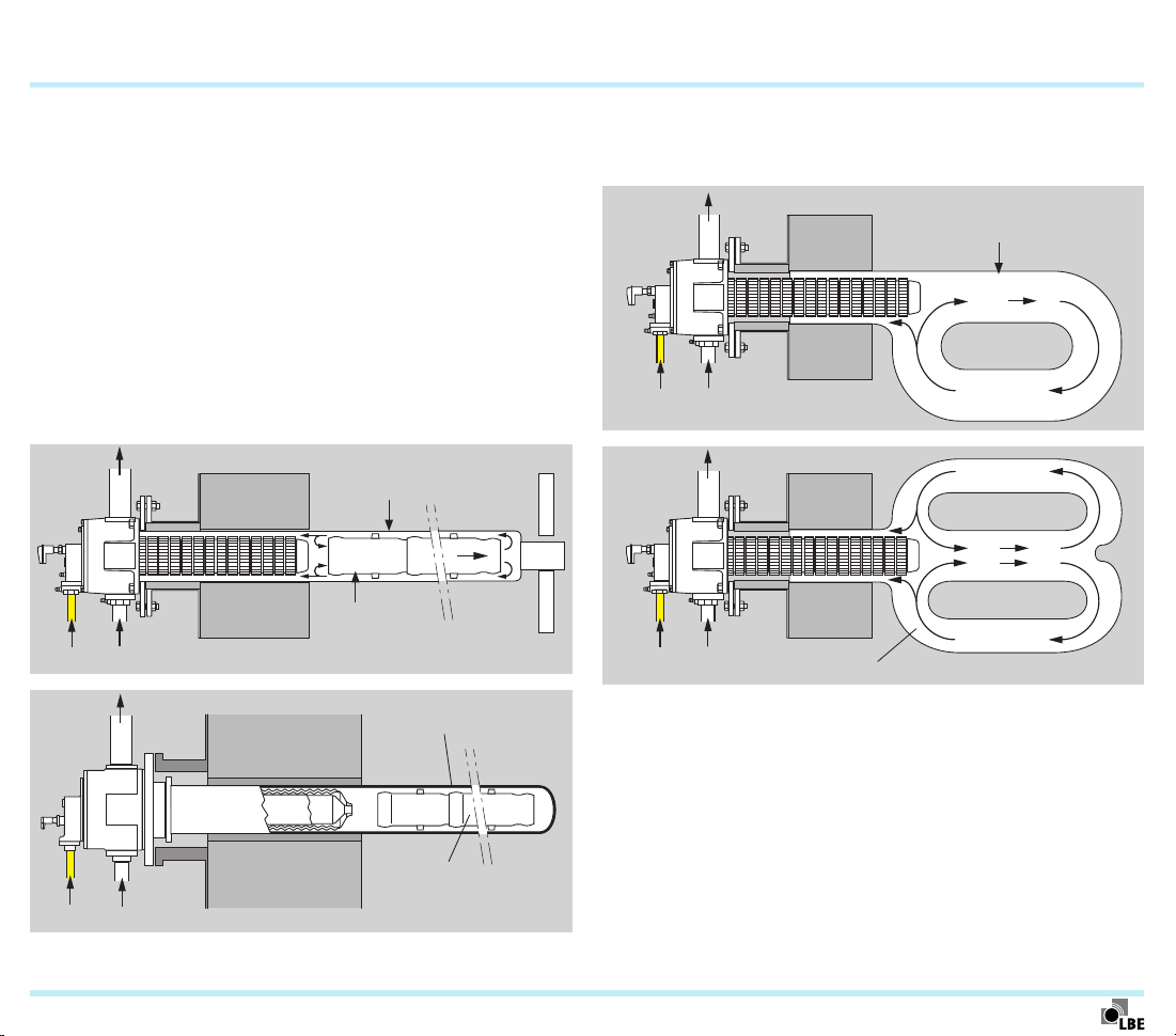
1.3.1 ECOMAX® in radiant tubes
The high outlet velocity of the combustion gases generates a
pressure at the outlet of the ceramic burner tube, resulting in
the recirculation of the flue gases. This leads to the following:
– a reduction in NOx emissions,
– a uniform radiant tube temperature.
The hot flue gases are fed through the ceramic or metallic heat
exchanger, heating the additional supply of cold combustion
air flowing in the opposite direction. The maximum achievable
air preheat temperature amounts to approx. 700°C, depending on the application.
Flue gas
Gas Cold air
Flue gas
Metallic radiant tube
®
Sicaflex
Ceramic radiant tube
SER-C
SICAFLEX® segmented flame tubes must be fitted in the singleended (metallic or ceramic) radiant tube to guide the hot flue
gases.
Flue gas
P radiant tube
Gas Cold air
Flue gas
Gas Cold air
Twin P
radiant tube
Gas Cold air
ECOMAX · Edition 02.11
Flame tube
Page 7
Application > Examples of application
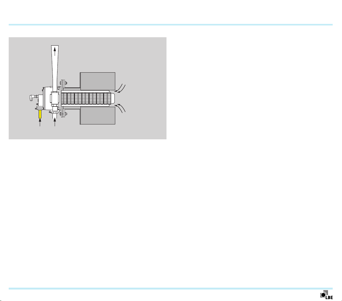
1.3.2 ECOMAX® in direct heating systems
Flue gas
Gas Cold air
ECOMAX® self recuperative burner in a direct heating system with an eductor for extracting the flue gases from the
furnace. The eductor generates a vacuum with a centrally
positioned nozzle and thus draws the flue gases out of the
furnace chamber through the burner’s heat exchanger. The
maximum achievable air preheat temperature amounts to
approx. 700°C, depending on the application.
7
ECOMAX · Edition 02.11
ECOMAX® with eductor and burner control unit BCU
Page 8
2 Certification
2.1 Approval for Russia
Certified by Gosstandart pursuant to GOST-R.
Approved by Rostekhnadzor (RTN).
8
ECOMAX · Edition 02.11
Page 9

9
3 Mechanical construction
The ECOMAX® burner unit is composed of four modules:
burner housing, recuperator, air guide tube and gas insert.
The modular design facilitates adapting the burners to the
respective application or integrating them into an existing
furnace system. Maintenance and repair times are reduced,
and existing furnace installations can easily be converted.
3.1 Burner housing
The burner housing accomodates the connections for the
combustion air, gas, cooling air and flue gas channelling. It
also secures the burner insert. It is made of cast aluminium,
which means it has a low weight. The housing has a doublewall design. The combustion air is fed into the burner via the
outer annular gap. This cools the burner housing und reduces
emissions.
3.2 Recuperator
All-ceramic
The surface of the all-ceramic recuperator, which is made
of SiSiC for high thermal stress, is burled in order to achieve
high efficiency.
Cast steel
The ribs on the cast steel recuperator offer a large surface area,
allowing it to achieve high efficiency even at low temperatures.
Flat tube
The flat tube recuperator has a smooth surface. It is a cost-
effective alternative at a lower efficiency level and is suitable
for lower application temperatures.
ECOMAX · Edition 02.11
Page 10

Mechanical construction
10
3.3 Air guide tube
Burners Ecomax..C have a ceramic air guide tube that for sizes
0 to 3 also serves as the combustion chamber.
Burners Ecomax..M and Ecomax..FTR have an air guide tube
made of heat-resistant steel.
3.4 Gas insert
The gas insert consists of the gas connection flange, the gas
lance with mixer unit and the ignition electrode (also serves
as monitoring electrode). For operation with LCV gas, the gas
insert is equipped with a special mixing system.
Gas insert with combustion chamber for Ecomax M and Ecomax FTR
ECOMAX · Edition 02.11
Gas insert without combustion chamber for Ecomax C (sizes 1 to 3)
Page 11
Mechanical construction > Gas insert
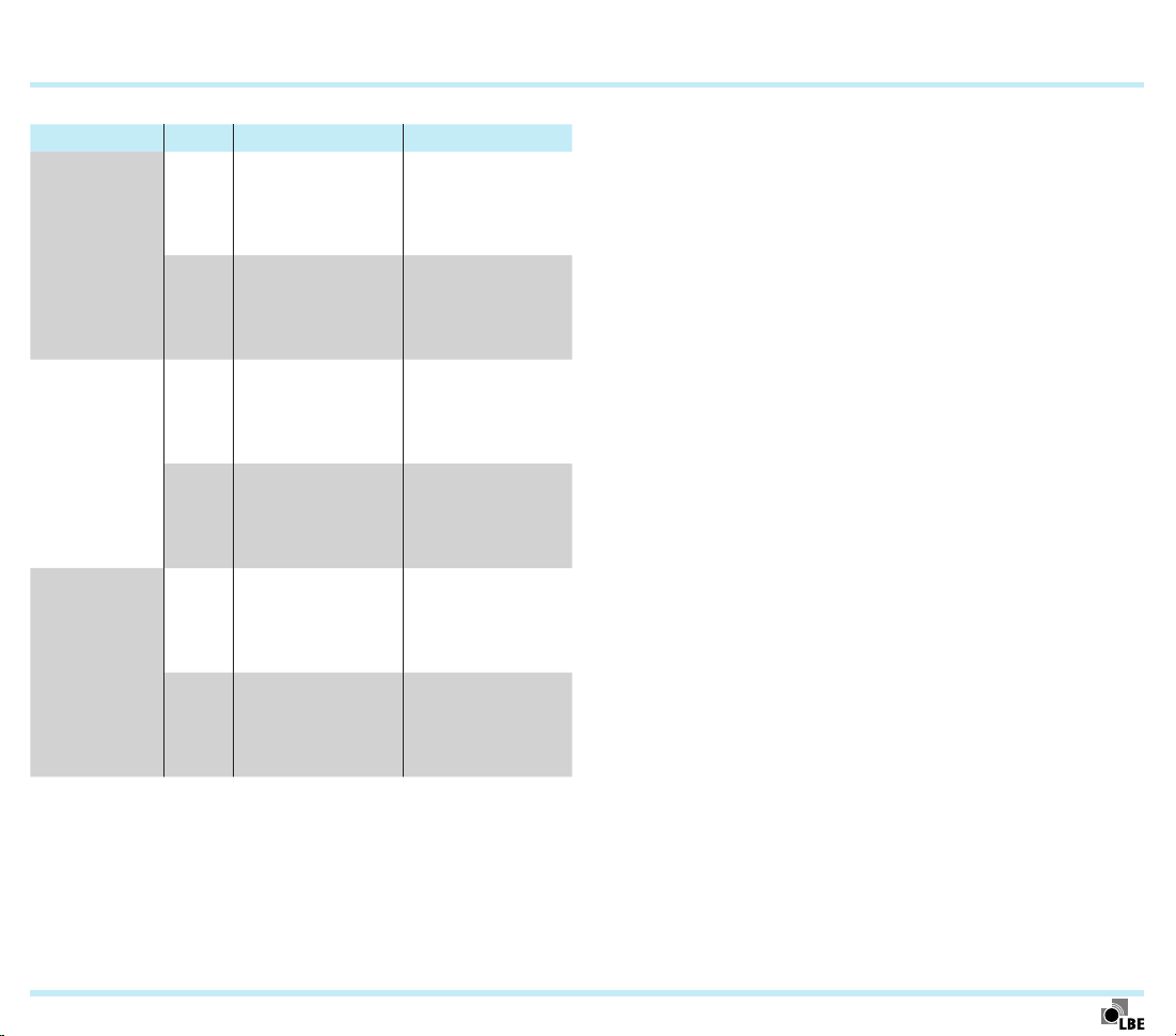
3.4.1 Versions
Burner Size Gas insert Air guide tube
Ceramic,
ECOMAX..C
ECOMAX..M
ECOMAX..FTR
0 – 3
4 – 5
1 – 3
4 – 6
1 – 3
4 – 5
With mixing
funnel
With swirl plate
and ceramic
combustion
chamber
With mixing funnel and ceramic
combustion
chamber
With swirl plate
and ceramic
combustion
chamber
With mixing funnel and ceramic
combustion
chamber
With swirl plate
and ceramic
combustion
chamber
with integrated
combustion
chamber
Ceramic
Metallic
Metallic
Metallic
Metallic
11
ECOMAX · Edition 02.11
Page 12
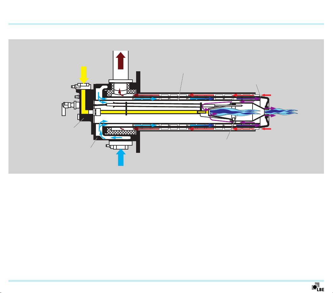
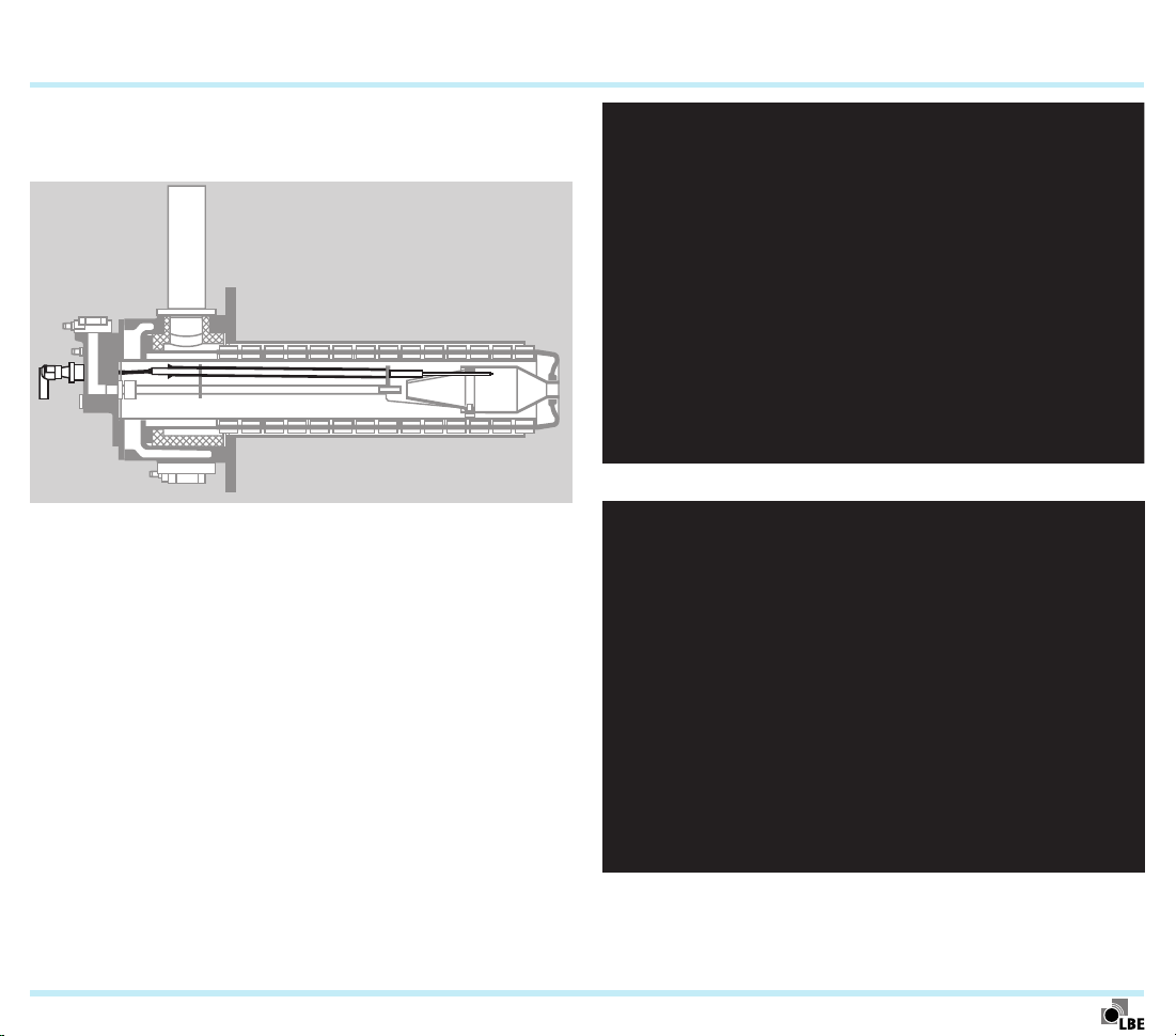
4 Function
Combustion air
12
Flue gas
Combustion gas
Air guide tube
Recuperator
Gas insert
Combustion chamber
Housing
The self recuperative burner ECOMAX® uses the heat from the
flue gases to preheat the combustion air. The heat exchanger
(recuperator) required for this is part of the burner.
After entering the burner, the combustion air flows in the gap
between the air guide tube and the inside of the recuperator
towards the tip of the burner. Some of this air is fed into the
inside of the burner, where it combusts in the first combustion
stage. The rest of the combustion air flows out through the gap
between the combustion chamber and the recuperator head
at high speed before combustion takes place in the second
combustion stage here. This process means that fewer pollutant emissions are produced.
ECOMAX · Edition 02.11
The hot flue gases, flowing in the opposite direction, leave the
furnace chamber on the outside of the recuperator. Heat is exchanged between the hot flue gases and the cold combustion
air through the recuperator wall. The burner is directly ignited.
Page 13

5 Selection
5.1 Burner type
The burner ECOMAX is available with a ceramic burled
tube recuperator (Ecomax..C), a cast steel ribbed tube recuperator (Ecomax..M) or a metallic flat tube recuperator
(Ecomax..FTR). Selection is dependent on the type of heating
and the furnace temperature.
Furnace temperature [°C]
Burner
direct indirect*
Ecomax..C 1300 approx. 1200
Ecomax..M 1150 approx. 1000
Ecomax..FTR 950 approx. 850
* The max. allowable temperature of the radiant tube must
be observed.
Heating
13
ECOMAX..C
ECOMAX..M
ECOMAX · Edition 02.11
ECOMAX..FTR
Page 14
Firing efficiency η
Selection
14
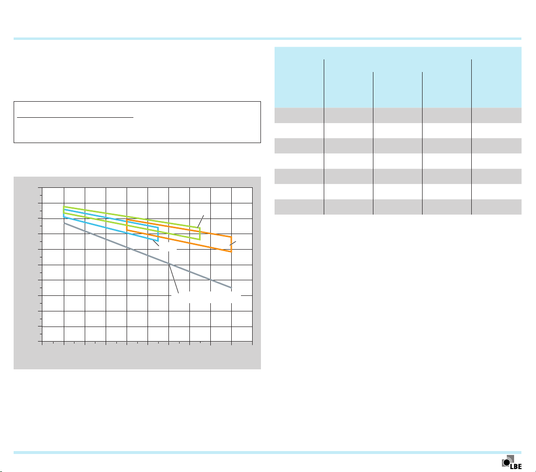
5.2 Burner design
Selection of the burner size is dependent on the net heat output.
From this, the required burner output is calculated using the
firing efficiency value.
Net heat output [kW]
Firing
efficiency η
Determine the firing efficiency for the desired furnace temperature using the diagram.
1
0,9
0,8
0,7
0,6
0,5
0,4
0,3
0,2
0,1
0
400 500 600 700 800 900 1000 1100
Flue gas temperature on recuperator inlet [°C]
= Burner output [kW]
M
FTR
Cold air burner
1200
1300
C
1400
Burner
Recuperator Output*
Size
ceramic
C
Ecomax 0
Ecomax 1
Ecomax 2
Ecomax 3
Ecomax 4
Ecomax 5
Ecomax 6 –
= available.
* For operation with natural gas. For operation with coke oven gas,
the output is approx. 80%, for operation with LCV gas, approx.
65%.
metallic
M
metallic,
flat tube
FTR
– – 25
– 500
[kW]
36
60
100
180
250
Precise dimensioning is available on request using the
ECOMAX calculation tool. For this, the following information
is required:
– Type of heating
– Furnace temperature
– Required net heat output
– Gas type
– Geometric furnace data (wall thickness, furnace extension,
clear width)
ECOMAX · Edition 02.11
Page 15
Selection
15
5.3 Gas types
Calorific value
Gas type Code letter
Natural gas L
and H quality
Propane, propane/butane,
butane
Town gas,
coke oven
gas
LCV gas L 1.7 – 3.9 0.9 –1.15
The output of the burners – see page 14 (Burner design) – refers
to natural gas and LPG.
In the case of coke oven gas, the output of the burners is
reduced to about 80%; higher outputs are only possible with
higher supply pressure.
In the case of LCV gas, the output of the burners is reduced
to about 65% of the rated output.
B 8 – 12 0.7– 0.9
G 25 – 35 2.0 – 2.7
D 4 – 6 0.4 – 0.6
range
[kWh/m3(n)]
Density ρ
[kg/m3]
5.4 Burner length
The burner length G should be selected so that the burner is
flush with the inside edge of the furnace lining (S1 = 0 ± 20 mm).
P1
N1
M1
G
K1
L1
S1
ECOMAX · Edition 02.11
Page 16
Selection
16
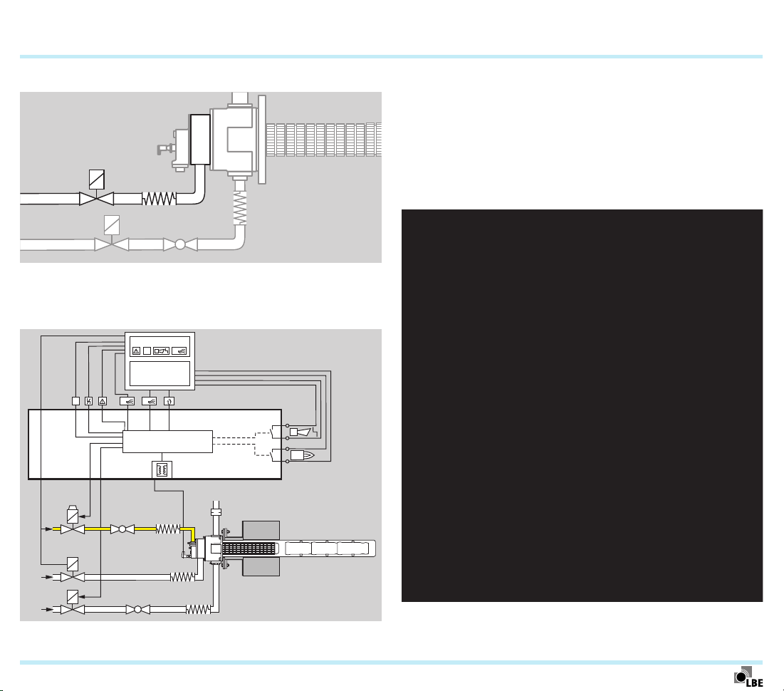
5.5 Connection for additional furnace cooling
The air volume supplied to the burner in cooling mode can
be increased using an optional intermediate flange with an
additional cooling air connection on the burner ECOMAX.
L1, N, PE
DI
P
PLC
DI
32
6
3
33
12
A
P
5
23
22 4
19
BCU 465..C
18
17
16
µC
26
Depending on the technical requirements for the process, cooling can be implemented in two stages. Actuating the air valve
for the burner (terminal 22) initiates “normal” cooling; actuating
a second air valve for the additional cooling air connection
initiates additional cooling. The additional cooling air valve is
actuated separately by the process control system. For wiring
on site, we recommend using a BCU..C with a supplementary
terminal strip (e.g. terminals 32/33 for additional air valve).
VG..L
GEH
VR..N
ECOMAX · Edition 02.11
EKO
Additional purging air connection on the ECOMAX® burner
Page 17

Selection
17
5.6 Differential air pressure measuring kit DA 1
For adjusting the air volume, especially for direct heating, we
recommend using the optional intermediate flange for differential pressure measurement.
The differential air pressure measuring kit DA1 is fitted at the
factory.
Order No. For burners
22800614 ECOMAX 1, 2
22800615 ECOMAX 3, 4, 5
22800666 ECOMAX 6
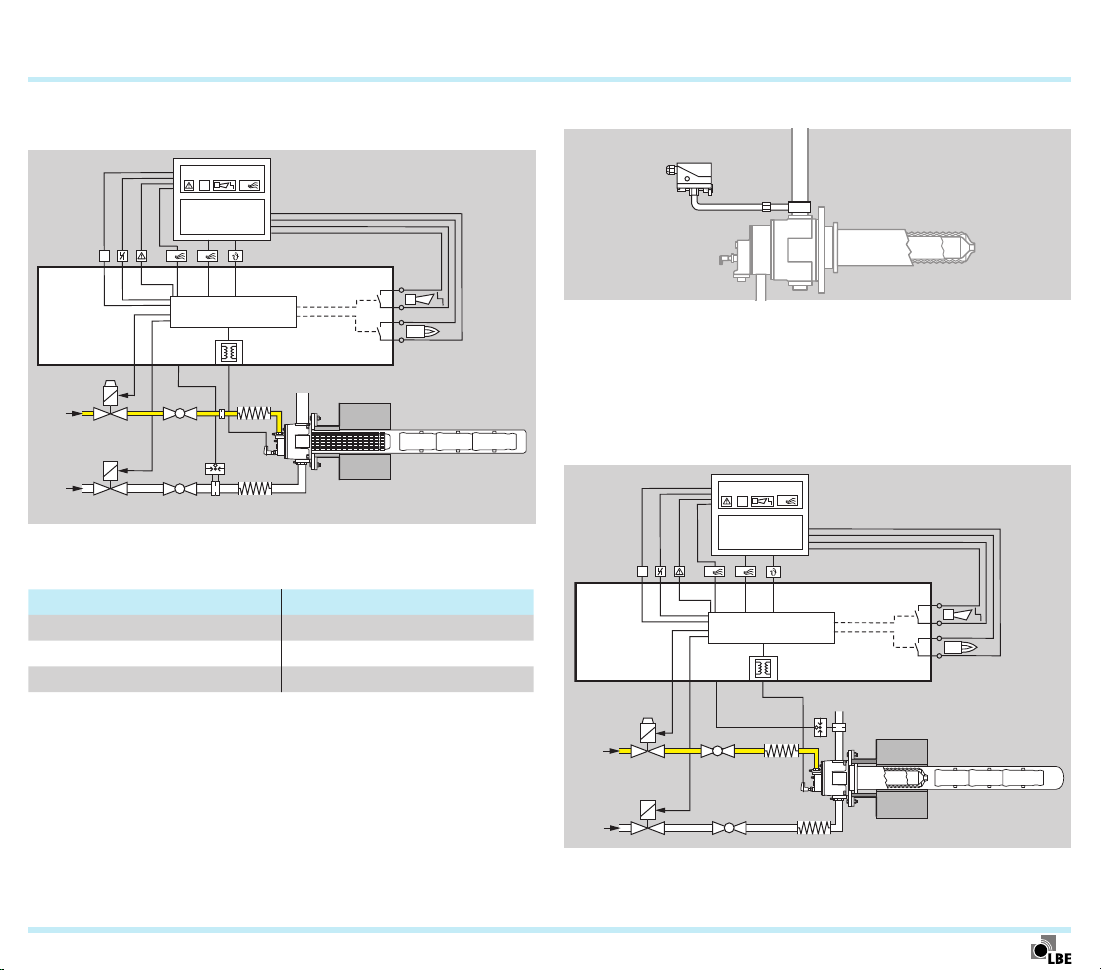
5.7 Differential air pressure measuring kit DA2 with
pressure switch
The differential air pressure measuring kit DA2 is used for the
automatic monitoring of the air flow on the burner ECOMAX® in
conjunction with the burner control unit BCU465– see page24
(Recommended burner control units) The pressure switch
monitors the air flow during pre-purge and burner operation.
If there is no air pressure, the burner is switched off via the
pressure switch, or the burner is not enabled.
Differential air pressure measuring kit DA 1 on the ECOMAX® burner
ECOMAX · Edition 02.11
Page 18
Selection
18
The pressure switch switching point should be set to approx.
80% of the differential pressure in normal operation.
L1, N, PE
DI
P
PLC
BCU 465..L
VG..L
VR..N
DI
6
3
12
A
P
5
23
22 4
19
ECOMAX
18
17
16
µC
26
21
EKO
GEH
The differential air pressure measuring kit DA2 is fitted at
the factory.
Order No. For burners
22800971 ECOMAX 1, 2
22800972 ECOMAX 3, 4, 5
22800973 ECOMAX 6
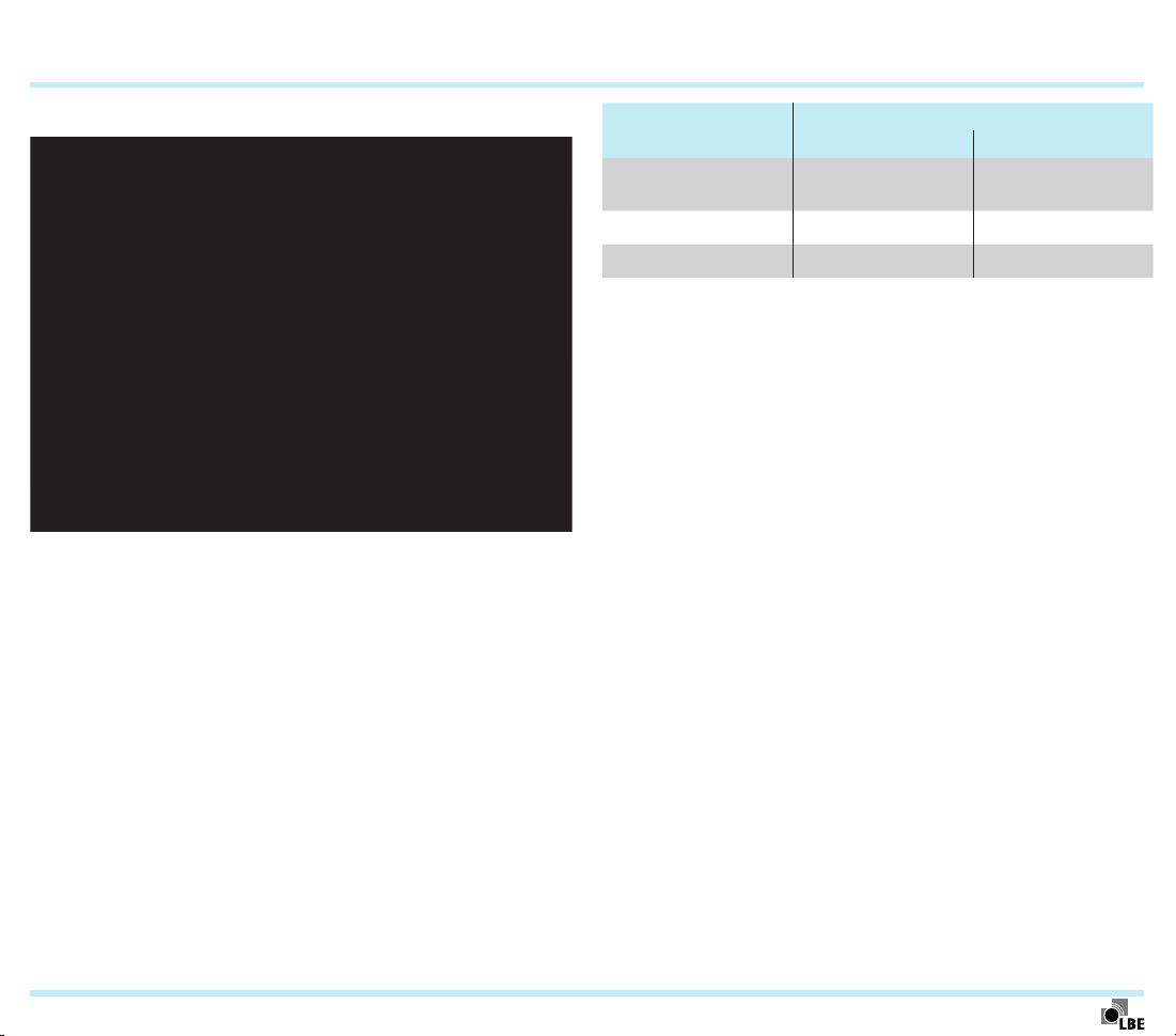
5.8 Flue gas monitoring kit DW
The flue gas monitoring kit DW with pressure switch is used in
conjunction with the burner control unit BCU465– see page24
(Recommended burner control units)– on ceramic radiant
tubes for automatically checking for ruptures. The pressure
switch monitors the flow rate of air and/or flue gas during
pre-purge and burner operation.
L1, N, PE
DI
P
PLC
BCU 465..L
DI
6
3
12
A
P
5
23
22 4
19
µC
26
21
18
17
16
ECOMAX · Edition 02.11
VG..L
VR..N
GEH
EKO
Page 19

Selection
When using the flue gas monitoring kit DW, the fan pressure
must be 10mbar higher, as the measuring orifice causes a
pressure loss in the flue gas pipe.
19
ECOMAX · Edition 02.11
Page 20

Selection
1)
2)
3)
t
5.9 Selection table
20
B D G L1)395 475 545 556 593 595 613 617 636 641 645 681 689 695
ECOMAX 0C
ECOMAX 1C
ECOMAX 2C
ECOMAX 3C
ECOMAX 4C
ECOMAX 5C
ECOMAX 1M
ECOMAX 2M
ECOMAX 3M
ECOMAX 4M
ECOMAX 5M
ECOMAX 6M
ECOMAX 1FTR
ECOMAX 2FTR
ECOMAX 3FTR
ECOMAX 4FTR
ECOMAX 5FTR
On request.
Orifi ce size on request.
If “none”, this specifi cation is omitted.
●
= standard, = available
● ● ● ● ● ● ● ● ●
● ● ● ● ● ● ● ● ●
● ● ●
● ● ●
● ● ●
● ● ●
● ● ● ● ● ● ● ● ●
● ● ●
● ● ●
● ● ●
● ● ●
● ● ●
●
●
●
●
●
● ●
●
●
●
●
Order example
ECOMAX 3MB545-100P0DA1
-22 to -5002)P03)K3)A3)DA13)DA23)DW3)T3)S3)Z
●
●
● ● ● ● ●
● ● ● ● ●
● ● ●
● ● ●
●
●
●
●
3)
● ● ● ● ● ●
● ● ● ● ● ●
● ● ● ● ● ●
● ● ● ●
●
●
●
●
●
● ●
●
●
●
●
●
ECOMAX · Edition 02.11
Page 21

Selection > Selection table
1)
2)
3)
4)
5.9.1 Type code
Code Description
ECOMAX Burner type
0
1
2
3
4
5
6
M
C
FTR
B
D
G
1)
L
395 to 695 Burner length in mm
-22 to -500
3)
P0
3)
K
3)
A
3)
DA1
3)
DA2
3)
DW
3)
T
3)
S
3)
Z
On request.
Orifi ce size on request.
If “none”, this specifi cation is omitted.
Other gas types on request.
Burner size (max. burner output with natural gas):
Recuperator: metallic
metallic, fl at tube variant
Gas type4): natural gas
coke oven gas
2)
Orifi ce for burner output in kW
Gas fl ange with purging air connection
Additional cooling air connection
Kanthal electrode
Differential air pressure measuring kit
Differential air pressure measuring kit with pres-
Flue gas monitoring kit with pressure switch
NPT connection
Spacer for SICAFLEX® fl ame tube
Special version
5 (250 kW)
6 (500 kW)
sure switch
21
0 (25 kW)
1 (36 kW)
2 (60 kW)
3 (100 kW)
4 (180 kW)
ceramic
LPG
LCV gas
2)
ECOMAX · Edition 02.11
Page 22
6 Project planning information
6.1 Flame control
The flame is monitored by a combined ignition/ionization
electrode as standard.
Flame control with UV sensor is only necessary if furnace
temperatures of 1050°C for direct heating or 950°C for indirect
heating are exceeded. Furthermore, we recommend using
bend-resistant Kanthal electrodes for ignition (standard with
ECOMAX..C) in this case.
We recommend the UV sensor UVS10D1 with integral purging
air connection (Order No.84315202) for burner length545.
For burner lengths greater than 545mm and for burner size
Ecomax0, the UV sensor UVS10L1 (Order No.84315203) with
lens is required. For attaching the UVS10, an adapter set EcoUVS10/E (Order No.22800079) is available.
22
ECOMAX® burner with ionization control
ECOMAX · Edition 02.11
ECOMAX® burner with UV control
Page 23

Project planning information
23
6.2 Purging air and cooling air
Purging air must be connected to the burner Ecomax in order
to ensure safe ignition and monitoring, and in order to avoid
problems caused by condensation and/or overheating:
– At temperatures above 950°C in the case of indirect heat-
ing and horizontal burner installation to prevent the ce-
ramic insulation of the ignition electrode from overheating.
Heating
horizontal –
Indirect
vertical
Direct
ECOMAX 0–6 ECOMAX 0–3 ECOMAX 4–5 ECOMAX 6
< 950°C > 950°C
Purging air on UV sensor,
P3 set Eco 2.5 /B
Purging air on electrode,
P2 set Eco 2.5 /E
Purging air on electrode,
P2 set Eco 2.5 /E
Purging air on UV sensor,
P3 set Eco 2.5 /B
Purging air on electrode,
P2 set Eco 2.5 /E
Purging air on UV sensor,
P3 set Eco 2.5 /B
– In the case of indirect heating and vertical burner installa-
tion, irrespective of temperature, in order to prevent condensation forming in the burner. Otherwise the flue gas
will enter the burner due to thermal lift.
– In the case of direct heating, irrespective of temperature,
in order to prevent condensation forming in the burner.
Otherwise, the flue gas will enter the burner, due to the
furnace pressure.
The required purging air volume is approx. 0.5 to 1.0% of the
3
air volume for rated output, or a minimum of 1 Nm
/h.
The purging air is connected to the purging air connection on
the gas flange next to the electrode, or in the case of UV control
to the purging air connection of the UV sensor. The purging air
is tapped upstream of the air control valve so that the purging
air continues to flow even if the burner is switched off.
In order to limit the volume of purging air, special nozzles can
be used which are adjusted to the required air supply pressure
for the ECOMAX– see page 51 (P2/P3 set Eco).
Furnace chamber temperature
Purging air on UV sensor,
P3 set Eco 4.0 /B
Purging air on UV sensor,
P3 set Eco 4.0 /B
950°C to 1050°C
Purging air on electrode,
P2 set Eco 2.5 /E
> 1050°C
Purging air on UV sensor,
P3 set Eco 4.0 /B
Purging air on electrode,
P2 set Eco 4.0 /E
Purging air on UV sensor,
P3 set Eco 4.0 /B
–
–
ECOMAX · Edition 02.11
Page 24
Project planning information
24
6.3 Recommended burner control units
ECOMAX burners, indirectly heated, with burner control unit
BCU465
Depending on the type of heating, we recommend operating
ECOMAX burners with the burner control units BCU460..L..8
or BCU465..L..8. When using burners ECOMAX..K with the
additional cooling air connection, we recommend operation
with a burner control unit BCU..C with additional circuit board
for signal distribution.
For ignition, the ECOMAX burners require an ignition transformer with 7.5kV high voltage and an output current of 20mA
at a duty cycle of 33%. An appropriate ignition transformer is
already integrated in burner control units BCU460..L..8 and
BCU465..L..8.
On request, we can also provide parameter lists for the programmable air supply and air post ventilation on the BCU465.
Heating
SER-C (ceramic radiant tube)
Metallic radiant tube
Direct
1)
Pre-purge is required following a false start in order to avoid
damage to the radiant tubes and flame tubes.
2)
In conjunction with an optional flue gas monitoring kit, see page
18 (Flue gas monitoring kit DW)
3)
In conjunction with a differential air pressure measuring kit, see
page .17 (Differential air pressure measuring kit DA2 with pressure switch)
4)
For burners with an additional cooling air connection
(ECOMAX..K), use burner control unit BCU460-3/1LW8AC.
5)
For burners with an additional cooling air connection
(ECOMAX..K), use burner control unit BCU465-3/1LW8AC.
Recommended burner control unit
BCU 460..L..8 BCU 465..L..8
1), 2), 5)
1), 5)
3), 5)
–
–
4)
ECOMAX · Edition 02.11
Page 25

Project planning information
25
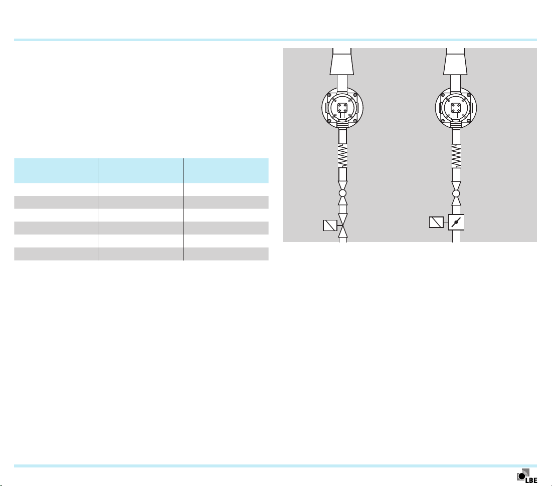
6.4 Gas connection
®
ECOMAX
L = 3× – 5× DN
EKO
GEH
VG..L
VG..N
Approx. 60 to 80mbar gas pressure should be present at
the gas connection of the ECOMAX burner. Furthermore, the
pressure losses due to pipework and valves are to be taken
into consideration.
For adjusting the burners, we recommend measuring the
flow rate using the integrated orifice. The orifice is designed
according to the burner output and gas type.
To ensure accurate measurements of the pressure differential
on the integrated orifice, the following boundary conditions for
the design of the gas connection must be taken into account:
– A straight inlet section which is 3 to 5 times as long as
the nominal diameter of the connection must be provided
upstream of the orifice. The attachment of a coupling, a
bellows unit or a pipe bend directly upstream of the ori-
fice can cause turbulence in the gas flow resulting in the
burner being incorrectly adjusted.
– All valves and fittings should have the same nominal size.
– Use bends with the largest possible radii.
– The pressure loss of the integrated orifice is approximate-
ly 10mbar.
6.4.1 Valves
A slow opening and quick closing gas valve is to be used as
an automatic shut-off valve. A quick opening and quick closing gas valve is to be installed as a second automatic shut-off
valve, unless the relevant application standard allows using
a single valve.
For burners ECOMAX® 4, 5 and 6, as an alternative to two
individual valves VAS..L and VAS..N, a double solenoid valve
VCS can be used.
Burner 1st gas valve
1)
2nd gas valve
1)
Ecomax 0 VG 15..L VG 15..N
Ecomax 1 VG 15..L VG 15..N
Ecomax 2 VG 15..L VG 15..N
Ecomax 3 VG 15..L VG 15..N
Ecomax 4 VAS 120..L
Ecomax 5 VAS 125..L
Ecomax 6 VAS 225..L
1)
For operation with natural gas.
2)
Alternatively, double solenoid valve VCS 120RLNW.
3)
Alternatively, double solenoid valve VCS 125RLNW.
4)
Alternatively, double solenoid valve VCS 225RLNW.
2)
3)
4)
VAS 120..N
VAS 125..N
VAS 225..N
2)
3)
4)
Instead of the stainless steel bellows unit EKO, a stainless
steel flexible tube ES can also be used. In this case, a higher
pressure loss must be taken into account.
ECOMAX · Edition 02.11
Page 26

Project planning information > Gas connection
26
6.4.2 Operation with LPG
For operation with LPG, it is essential to cool the gas lance via
a central air lance in order to prevent the LPG from cracking in
the gas lance and soot formation during combustion.
6.4.3 Air/gas ratio control
In order to ensure the required air/gas ratio when equipping
the burners with only gas and air valves without a pneumatic
ratio control system, precise control of the gas and air pressures, as well as monitoring of these pressures is necessary
in accordance with the relevant standards (e.g. EN746-2).
For pneumatic air/gas ratio control, we recommend the variable air/gas ratio control GVRH, which prevents the lambda
value from varying due to changes in the furnace temperature.
The central air volume is approx. 3 to 5% of the combustion
air volume and must also flow while the burner is switched off.
ECOMAX · Edition 02.11
Page 27
Project planning information
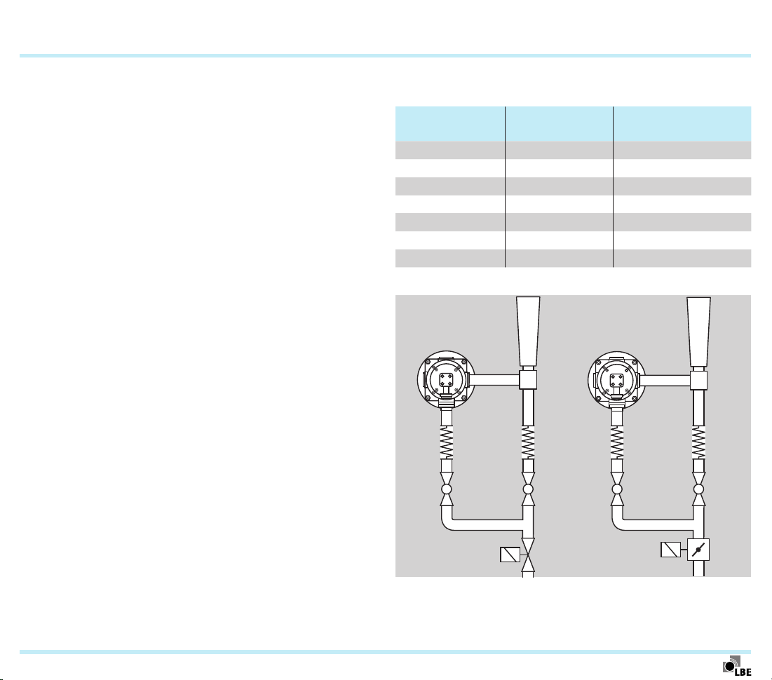
6.5 Air connection
6.5.1 Indirect heating
Approx. 60 to 80mbar air pressure should be present at
the air connection of the ECOMAX burner. Furthermore, the
pressure losses due to pipework and valves are to be taken
into consideration.
A quick opening, quick closing air valve or solenoid actuator
should be used.
ECOMAX 0
…
ECOMAX 4
27
ECOMAX 5
Burner Air valve
Butterfly valve/so-
lenoid actuator
Ecomax 0 VR 20..N –
Ecomax 1 VR 25..N –
Ecomax 2 VR 40..N –
Ecomax 3 VR 50..N –
Ecomax 4 VR 65..N –
Ecomax 5 – BVHM 65/MB 7
VR..N
Other types of control on request.
+
MB 7
BVHM
ECOMAX · Edition 02.11
Page 28
BVHM
Project planning information > Air connection
28
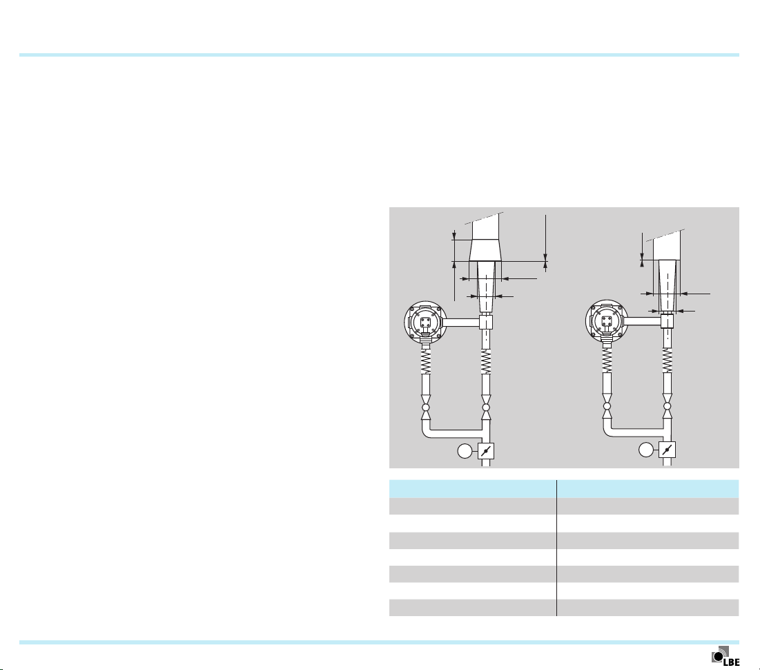
6.5.2 Direct heating
Approx. 90 to 100 mbar air pressure should be present at the
eductor. Furthermore, the pressure losses due to pipework
and valves are to be taken into consideration.
For burner adjustment, we recommend using the differential
air pressure measuring kit DA1– see page17 (Differential air
pressure measuring kit DA 1).
To ensure accurate measurement of the pressure differential,
the following boundary conditions for the design of the air
connection must be taken into account:
– A straight inlet section which is 3 to 5 times as long as the
nominal diameter of the connection must be provided up-
stream of the differential air pressure measuring kit DA1.
– All valves and fittings should have the same nominal size
and nominal connection diameter.
– Use bends with the largest possible radii.
– The pressure loss of the measuring orifice is approx.
6mbar.
A quick opening, quick closing air valve or solenoid actuator
should be used.
Burner Air valve
Butterfly valve/sole-
noid actuator
Ecomax 0 VR 40..N –
Ecomax 1 VR 50..N –
Ecomax 2 VR 65..N –
Ecomax 3 – BVHM 65/MB7NM3
Ecomax 4 – BVHM 80/MB7NM3
Ecomax 5 – BVHM 80/MB7NM3
Ecomax 6 BVHM 100/MB7NM3
ECOMAX 0
ECOMAX 1
ECOMAX 2
ECOMAX 3
…
ECOMAX 6
ECOMAX · Edition 02.11
VR..N
Other types of control on request.
+
MB 7
Page 29

P1
Project planning information
29
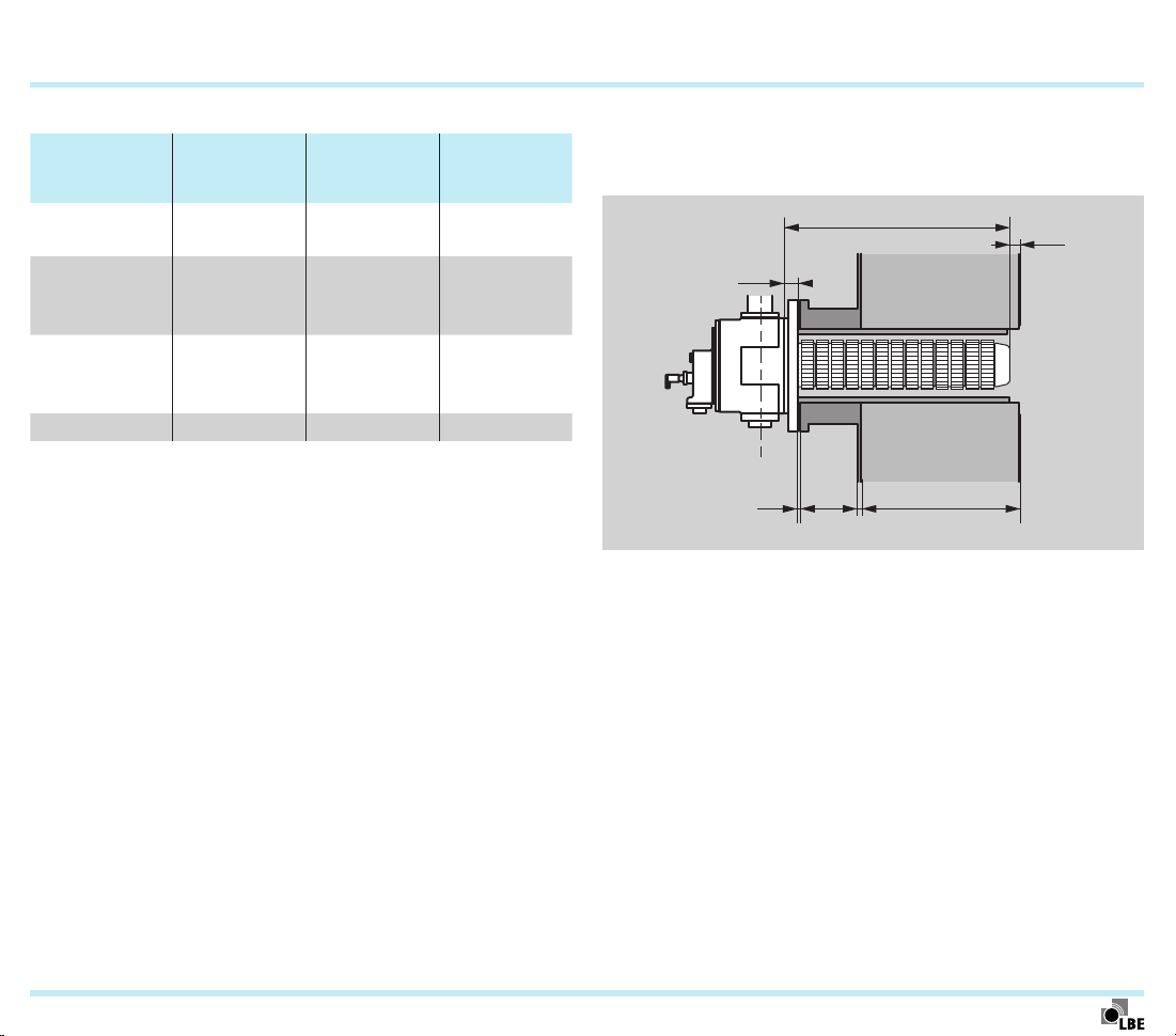
6.6 Flue gas guide tube FGT for direct heating
When using the ECOMAX® burners on direct heating installations, a flue gas guide tube FGT kit is required (see page) 49
(Flue gas guide tube FGT kit).
The flange thickness P1 of the flue gas guide tube is 15mm.
Plan the height of the furnace extension so that the front edge
of the recuperator is flush with the inside edge of the furnace
lining (S1= 0± 20mm).
The FGT is to be insulated with Cerablanket or similar mate-
rial, so that no hot furnace atmosphere reaches the furnace
extension.
6.6.1 For ECOMAX..C
Flue gas guide tube FGT
Furnace extension
Burner
FGT external ∅ A
in mm
ECOMAX 0C 140
ECOMAX 1C 180
ECOMAX 2C 200
ECOMAX 3C 236
ECOMAX 4C 300
ECOMAX 5C 336
S1
∅A
ECOMAX · Edition 02.11
Page 30

P1
Project planning information > Flue gas guide tube FGT for direct heating
6.6.2 For ECOMAX..M
Flue gas guide tube FGT
S1
∅A
Furnace extension
30
Burner
FGT external ∅ A
in mm
ECOMAX 1M 133
ECOMAX 2M 156
ECOMAX 3M 193
ECOMAX 4M 254
ECOMAX 5M 287
ECOMAX 6M 390
ECOMAX · Edition 02.11
Page 31

Project planning information
31
6.7 Radiant tubes
For indirect heating, different combinations of radiant tubes
and ECOMAX burners can be used.
The metallic burners Ecomax M or FTR are used in metallic
radiant tubes (single-ended radiant tube, P radiant tube or
twin P radiant tube). The ceramic burners EcomaxC are used
in ceramic single-ended radiant tubes, see page6 (ECOMAX®
in radiant tubes).
Depending on the geometry, flue gas guide tubes may be
needed for radiant tubes and additional adapter flanges may
be required for the metallic single-ended radiant tube.
In special cases, a ceramic burner EcomaxC can be installed
in a metallic radiant tube. Special flue gas guide tubes are
needed here in order to avoid damage to the ceramic burner
due to deformation of the metallic tube.
6.7.1 Ceramic radiant tube SER-C for indirect heating
Install the radiant tube free of mechanical stress.
Ensure that there are threaded bolts on the furnace flange to
attach the ceramic radiant tube to the furnace.
Ensure that there is an annular gap of ≥20mm between the
radiant tube and the furnace lining.
of the radiant tube SER-C is either 32 or 37mm, depending
on the size.
Plan the height of the furnace extension so that the front
edge of the recuperator is flush with the interior furnace wall
(S1 = 0 ± 20 mm).
Loosely wrap a Cerablanket mat or similar material around
the radiant tube before installing it in the furnace.
The flange thickness P1
Installation dimensions
P1
≥ 8 mm
B1
Furnace
extension
Compression fitting
SER-C com-
pression
Burner
fitting
∅ B1
in mm
SER-C 100/088
SER-C 142/128
SER-C 162/148
SER-C 202/188
160 100 140
200 142 180
220 162 200
260 202 240
Annular gap
Ceramic radiant tube ∅ X
in mm
S1
∅X
Lining
∅ Y
in mm
∅Y
ECOMAX · Edition 02.11
Page 32

Project planning information > Radiant tubes
32
6.7.2 Metallic radiant tube
Install the radiant tube free of mechanical stress.
Ensure that there is an annular gap of ≥20mm between the
radiant tube and the furnace lining.
Insulate the metallic radiant tube with a 20mm Cerablanket
mat or similar material.
Plan the height of the furnace extension so that the front edge
of the recuperator is flush with the interior furnace wall (S1=
0± 20mm).
The burner Ecomax M can be installed in different me-
tallic radiant tubes: single-ended radiant tubes SER-M,
P radiant tubes or twin P radiant tubes.
The metallic radiant tubes are available in a variety of dimen-
sions in either centrifugal casting or in welded form. The efficiency of the burner EcomaxM is determined by the internal
diameter di of the radiant tubes in the vicinity of the burner.
The following dimensions are recommended:
Burner
Radiant tube internal diameter d
[mm]
i
recommended min.
ECOMAX 1M 128 ≤ 127
ECOMAX 2M 148 ≤ 147
ECOMAX 3M 187 ≤ 184
ECOMAX 4M 250 ≤ 246
ECOMAX 5M 280 ≤ 280
6.7.3 Radiant tube distances
For furnace temperatures > 600°C:
∅X
1.2X
1.2X
2.5X
The centre to centre distance of the radiant tubes should be
≥ 2.5 d. The distance of the radiant tubes from the furnace
wall, from the furnace floor or from the material to be heated
should be ≥1.2 d.
For furnace temperatures < 600°C with air circulation of 15 m/s:
≥100
mm
≥100
mm
ECOMAX · Edition 02.11
≥100 mm
The distance of the radiant tubes from one another and from
the furnace wall should be ≥100mm.
Page 33

Project planning information > Radiant tubes
6.7.4 Eductor on burners with metallic single-ended radiant tubes
The eductor ensures negative pressure in the radiant tube.
This prevents the inert gas atmosphere in the furnace being
contaminated by flue gases from the burner in the event of
leakage from the single-ended radiant tube.
Flue gas
Metallic radiant tube
Gas Cold air
33
ECOMAX · Edition 02.11
Page 34

Project planning information
6.8 Flue gas channelling
A flue gas system must be fitted on the furnace as a means
of guiding the flue gas to the chimney.
In the flue gas system there should be a low negative pressure thanks to the draught of the chimney or an exhaust fan.
The eductor or the flue gas connector on the burner can be
equipped with protection against accidental contact, but they
must not be insulated.
6.8.1 Indirect heating
The flue gas system on the furnace should stop 10mm away
from the flue gas connector, or be fitted flush with the eductor.
For indirect heating with flue gas monitoring kit DW and
BCU465, excessive negative pressure in the flue gas system
or an excessively narrow flue gas pipe diameter on the furnace can cause problems with setting the switching point of
the pressure switch.
∅1.5Q
∅2Q
∅Q
M
∅1.5Q
∅2Q*
10 mm ±5
∅Q
0 mm
(±10 mm)
∅1.5P
10 mm ±5
M
M
* With flue gas monitoring kit DW; without flue gas monitoring kit
DW: 1.5Q to 2Q.
∅ Q ∅ P
ECOMAX 0 DN 32 43
ECOMAX 1 DN 50 43
ECOMAX 2 DN 50 73
ECOMAX 3 DN 65 79
ECOMAX 4 DN 100 98
ECOMAX 5 DN 100 98
34
∅P
ECOMAX · Edition 02.11
Page 35
Project planning information > Flue gas channelling
35
6.8.2 Direct heating
The eductors for flue gas extraction via the burner ECOMAX
cannot be used for furnace pressure control. For direct heating, we recommend discharging 10 to 15% of the flue gases
via an additional flue gas opening on the furnace fitted with
a furnace pressure control system.
In normal cases, for 90% of flue gas extraction, a low positive
pressure of between 0.1 and 0.3mbar can be maintained in
the furnace chamber. In the case of heavily leaking furnaces,
flue gas extraction must be reduced, where necessary, to
avoid pulling in cold air due to negative pressure in the furnace chamber.
For furnace temperatures ≥ 1000°C, it is recommended that
eductors with a mechanical flue gas valve (AGK) are used to
avoid these excessive temperatures.
The flue gas system on the furnace should be fitted flush with
the eductor (±10mm). The diameter of the flue gas pipe on the
furnace should be twice the eductor diameter P. If the diameter is
too small, even with the flue gas valve there is the danger of hot
flue gases creeping through the burner when it is switched off.
0 mm
(±10 mm)
∅2P
∅P
M
∅1.5P
∅2P
∅P
M
0 mm (±10 mm)
Flue gas extraction via the burner is adjusted based upon the
negative pressure measured on the eductor.
If the furnace temperature is too high, damage can occur
to burners which are switched off due to the flow of hot flue
gases over them.
ECOMAX · Edition 02.11
∅ P [mm]
ECOMAX 0 43
ECOMAX 1 43
ECOMAX 2 73
ECOMAX 3 79
ECOMAX 4 98
ECOMAX 5 98
ECOMAX 6 137
Page 36

Project planning information
6.9 Burner adjustment
Differential pressure curves are delivered with the burner documentation to enable adjustment of the air and gas volumes
thus changing the burner output accordingly.
6.9.1 Differential air pressure measuring kit DA2 with
pressure switch
The pressure switch should be set to approx. 80% of the pres-
sure differential in normal operation.
36
ECOMAX · Edition 02.11
Page 37

37
7 Technical data
Heating: direct with eductor or indirect in radiant tube.
Control type: On/Off.
Control range: approx. 1:3.
Flame velocity: approx. 120 to 150 m/s.
Flame control: direct ionization control (UV control as an
option).
Ignition: direct, electrical.
Recuperator:
ECOMAX..C:
ceramic (SiSiC), max. application temperature 1300°C,
ECOMAX..M:
cast steel, max. application temperature 1150°C,
ECOMAX..FTR:
metallic, max. application temperature 950°C.
Burner Output [kW] Flame length [mm]*
ECOMAX 0 25 250
ECOMAX 1 36 350
ECOMAX 2 60 450
ECOMAX 3 100 600
ECOMAX 4 180 800
ECOMAX 5 250 800
ECOMAX 6 500 800
* Visible range for natural gas operation in the open air,
max. connection rating and air index 1.15.
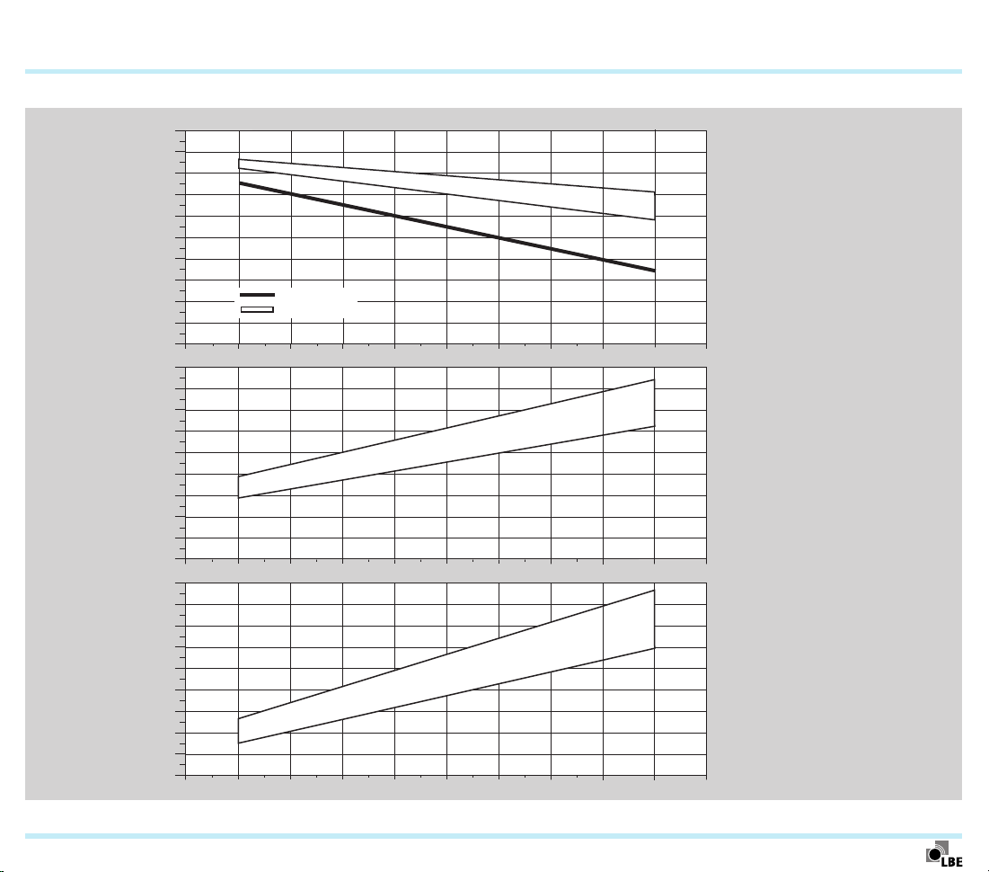
7.1 Efficiency
Heating: direct.
Flue gas extraction: 100%.
Lambda: 1.1.
Duty cycle: 80%.
Diagrams for efficiency, flue gas temperature and air preheat-
ing – see page 38 (ECOMAX..C), page39 (ECOMAX..M),
page 40 (ECOMAX..FTR).
For detailed information about the efficiency, contact us– see
page52 (Contact)
ECOMAX · Edition 02.11
Page 38
Technical data > Efficiency
7.1.1 ECOMAX..C
100
90
80
70
Efficiency [%]
60
50
40
30
20
10
0
900
800
700
600
500
400
300
200
100
Flue gas temperature [°C]
0
900
800
700
600
500
400
300
Air preheating [°C]
200
100
0
400 500 600 700 800 900 1000 1100
Cold air burner
ECOMAX..C
1200
1300
Temperature on
recuperator inlet
1400
[°C]
38
ECOMAX · Edition 02.11
Page 39

Technical data > Efficiency
7.1.2 ECOMAX..M
100
90
80
70
Efficiency [%]
60
50
40
30
20
10
0
900
800
700
600
500
400
300
200
100
Flue gas temperature [°C]
0
900
800
700
600
500
400
300
Air preheating [°C]
200
100
0
400 500 600 700 800 900 1000 1100
Cold air burner
ECOMAX..M
1200
1300
Temperature on
recuperator inlet
[°C]
1400
39
ECOMAX · Edition 02.11
Page 40

Technical data > Efficiency
7.1.3 ECOMAX..FTR
90
80
70
60
Efficiency [%]
50
40
30
20
10
0
900
800
700
600
500
400
300
200
100
Flue gas temperature [°C]
0
900
800
700
600
500
400
300
Air preheating [°C]
200
100
0
400 500 600 700 800 900 1000 1100
40
Cold air burner
ECOMAX..FTR
Temperature upstream
of recuperator
[°C]
ECOMAX · Edition 02.11
Page 41

M16
Technical data
t
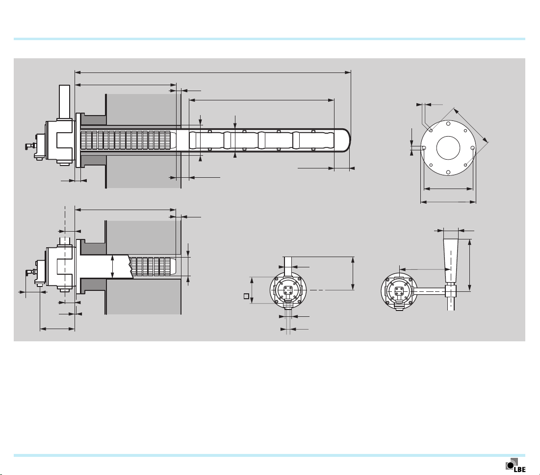
7.2 Dimensions
7.2.1 ECOMAX..C
P1
W1
E
B1
≥ 8 mm
41
W
G
G
S1
∅Y
S1
∅X
D1 (ECOMAX 0–3 = 30 mm)
C1
0.7 – 1.5 × ∅X
(ECOMAX 0 = M12)
∅ 18 mm
(ECOMAX 0 ∅ 14 mm)
I1
A1
F1
∅P
G1
ECOMAX · Edition 02.11
C
J1
D
∅A
∅B
H1
∅Q
∅U
∅J
T
K
M
Page 42

Technical data > Dimensions > ECOMAX..C
1)
2)
3)
4)
Type [mm]
∅ A ∅ B
C D E G
ECOMAX 0C 142 86 60 182 60 545–695
ECOMAX 1C 180 123 60 212 60 545–695
ECOMAX 2C 200 142 60 212 60 545–695
ECOMAX 3C 236 178 83 262 83 545–695
1)
∅ J
2)
R ½" 269 625 43 DN 32 297
2)
R ½" 269 625 43 DN 50 331
2)
R ½" 283 625 73 DN 50 331
2)
R ½" 292 820 79 DN 65 353
ECOMAX 4C 300 240 95 298 95 545 R ¾" 353 820 98 DN 100 399
ECOMAX 5C 336 273 95 298 95 695 R 1" 345 920 98 DN 100 399
K M
∅ P ∅ Q
42
T
Type [mm] Weight
∅ U
ECOMAX 0C R ¾"
W
∅ X ∅ Y
100 140 – 160
A1
∅ B1
C1 D1
30 – 90 182 210
∅ F1
G1
H1 ∅ I1
S1 kg
3)
ECOMAX 1C R 1" 142 182 280 200 30 330 90 236 290 20
ECOMAX 2C R 1½" 162 202 280 220 30 330 90 236 290 25
ECOMAX 3C R 2" 202 242 325 260 30 385 90 280 330 33
ECOMAX 4C R 2½" – – 420 – – 480 110 372 445 48
1000 – 2600
C1 =
n × 250 + 50
S1 =
ECOMAX 5C R 2½" – – 420 – – 480 110 372 445 57
Lengths > 695 mm in 100 mm increments (795, 895, 995 mm etc.); additional lengths on request.
545, 595, 645 or 695 mm
In increments of 100 mm. Other lengths on request.
For length G = 545 mm.
ECOMAX · Edition 02.11
4)
12
0 ± max. 20
Page 43
Technical data > Dimensions
t
7.2.2 ECOMAX..M
G
S1
∅Y
∅X
W
C1
43
M16
(ECOMAX 0 = M12)
(ECOMAX 6 = M20)
I1
G1
0,5 – 1,5 × ∅X
S1
∅B
D1
∅Q
ECOMAX 0 ∅ 14 mm
ECOMAX 6 ∅ 23 mm
ECOMAX 1 – 5 ∅ 18 mm
A1
F1
∅P
T
K
M
P1
G
E
∅A
H1
C
J1
D
∅U
∅J
ECOMAX · Edition 02.11
Page 44

1)
2)
3)
Technical data > Dimensions > ECOMAX..M
Type [mm]
∅ A ∅ B
C D E G
ECOMAX 1M 133 123 60 212 60 545–695
ECOMAX 2M 156 142 60 212 60 545–695
ECOMAX 3M 193 178 83 262 83 545–695
ECOMAX 4M 254 240 95 299 95 545–695
ECOMAX 5M 287 273 95 299 95 545–695
1)
∅ J
2)
R 1/2" 269 625 43 DN 50
2)
R 1/2" 283 625 73 DN 50
2)
R 1/2" 292 820 79 DN 65
2)
R 3/4" 353 820 98 DN 100
2)
R 1" 345 920 98 DN 100
ECOMAX 6M 390 370 150 400 150 695 R 1½" 530 1177 137 DN 150
Type [mm] Weight
T
∅ U
ECOMAX 1M 331 R 1" 280
A1 C1 D1
30 330 90 236 290
∅ F1
G1
ECOMAX 2M 331 R 1½" 280 30 330 90 236 290 48
ECOMAX 3M 353 R 2" 325 30 385 90 280 330 58
ECOMAX 4M 399 R 2½" 420 50 480 110 372 445 93
ECOMAX 5M 399 R 2½" 420 50 480 110 372 445 105
C1 =
n × 250 + 50
ECOMAX 6M 598 R 3" 690 50 740 150 550 650 228
Lengths > 695 mm in 100 mm increments (795, 895, 995 mm etc.); additional lengths on request.
545, 595, 645 or 695 mm
For length G = 545 mm.
K M
H1 ∅ I1
∅ P ∅ Q
S1 kg
S1 =
0 ± max. 20
3)
35
44
ECOMAX · Edition 02.11
Page 45

Technical data > Dimensions
t
7.2.3 ECOMAX..FTR
G
P1
W1
45
W
S1
C1
∅Y
∅X
0.5 – 1.5 × ∅X
D1
M16
(ECOMAX 0 = M12)
∅ 18 mm
(ECOMAX 0 ∅ 14 mm)
I1
A1
F1
E
G1
C
J1
D
ECOMAX · Edition 02.11
∅A
G
S1
∅B
∅Q
∅P
T
K
M
H1
∅U
∅J
Page 46

Technical data > Dimensions > ECOMAX..FTR
1)
2)
3)
Type [mm]
∅ A ∅ B
D E G
ECOMAX 1FTR 133 109 212 60 545–695
ECOMAX 2FTR 156 128 212 60 545–695
ECOMAX 3FTR 193 164 262 83 545–695
ECOMAX 4FTR 254 216 299 95 545–695
ECOMAX 5FTR 287 244 299 95 545–695
1)
2)
2)
2)
2)
2)
∅ J
K M
∅ P ∅ Q
R 1/2" 269 625 43 DN 50
R 1/2" 283 625 73 DN 50
R 1/2" 292 820 79 DN 65
R 3/4" 353 820 98 DN 100
R 1" 345 920 98 DN 100
46
Type [mm] Weight
T
∅ U
ECOMAX 1FTR 331 R 1" 280
A1 C1 D1
30 330 90 236 290
∅ F1
G1
H1 ∅ I1
S1 kg
27
ECOMAX 2FTR 331 R 1½" 280 30 330 90 236 290 28
ECOMAX 3FTR 353 R 2" 325 30 385 90 280 330 44
ECOMAX 4FTR 399 R 2½" 420 50 480 110 372 445 70
ECOMAX 5FTR 399 R 2½" 420 50 480 110 372 445 74
Lengths > 695 mm in 100 mm increments (795, 895, 995 mm, etc.); additional lengths on request.
545, 595, 645 or 695 mm
For length G = 545 mm.
C1 =
n × 250 + 50
S1 =
0 ± max. 20
3)
ECOMAX · Edition 02.11
Page 47

∅
L
∅
L
H1
1)
2)
Technical data > Dimensions
7.2.4 ECOMAX standard piping
ECOMAX 0
ECOMAX 1
ECOMAX 2
47
P
K
ECOMAX 3
ECOMAX 4
ECOMAX 5
ECOMAX 6
P
K
∅Q
T
∅Q
T
H1
N M
H
M
∅Z
∅J
Type [mm]
ECOMAX 0 670
ECOMAX 1 620
ECOMAX 2 620
ECOMAX 3 820
ECOMAX 4 660
ECOMAX 5 700
ECOMAX 6 990
± 20 mm.
± 10 mm.
H
1)
1)
1)
1)
1)
1)
1)
∅ J
R 1/2" 615
R 1/2" 591
R 1/2" 730
R 1/2" 775
R 3/4" 880
R 1" 765
R 1½" – – 598 DN 150 530 1375
R
∅ U
1)
R ¾" 230 DN 32 269 640
1)
R 1" 331 DN 50 269 690
1)
R 1½" 331 DN 50 283 765
1)
R 2" 353 DN 65 292 700
1)
R 2½" 399 DN 100 353 820
1)
R 2½" 399 DN 100 345 820
T
∅ Q
N M
∅Z
K L
ECOMAX 0
…
ECOMAX 4
R
∅U
∅ Z
2)
R 1½" 625 415
2)
R 2" 625 430
2)
R 2½" 625 466
2)
R 2½" 820 495
2)
R 3" 820 545
2)
R 3" 920 545
2)
R 4" 1177 1120
R
M N
2)
2)
2)
2)
2)
2)
2)
ECOMAX 5
∅U
∅ P
43
43
73
79
98
98
137
ECOMAX · Edition 02.11
Page 48

8 Maintenance
Twice per year, but if the media are highly contaminated, this
interval should be reduced.
48
ECOMAX · Edition 02.11
Page 49

49
9 Accessories
9.1 Flue gas guide tube FGT kit
When using the ECOMAX® burners for direct heating, a flue
gas guide tube FGT is required.
The FGT kit is available in lengths in various increments, which
are suited to different burner lengths.
For ECOMAX 1C, 2C und 3C, there is a standard version for
furnace temperatures up to 1200°C and a high temperature
version for furnace temperatures from 1200°C to 1300°C.
Scope of delivery: flue gas guide tube FGT with burner seal,
mounting gasket, as well as 4 threaded bolts, washers and
nuts for attaching it to the burner.
Order No. on request.
9.2 Flue gas eductor
For direct heating
The eductor generates a vacuum with a centrally positioned
nozzle and thus draws the flue gases out of the furnace
chamber through the burner’s heat exchanger.
On burners with metallic single-ended radiant tubes
The eductor ensures negative pressure in the radiant tube.
This prevents the inert gas atmosphere in the furnace being
contaminated by flue gases from the burner in the event of
leakage from the single-ended radiant tube.
For more information, see product brochure on the flue gas
eductor for self recuperative burners ECOMAX
Order No. on request.
®
.
ECOMAX · Edition 02.11
Page 50

Accessories
50
9.3 Ceramic radiant tube SER-C
For heat treatment processes in which combustion gases
must be kept separate from the product. The patented flange
connection is gas-tight.
Material: SiSiC, max. application temperature: 1300°C.
G
≥ 8 mm
B1
P1
W1
S1
∅Y
W
C1
∅X
0.7 – 1.5 × ∅X
D1 (ECOMAX 0–3 = 30 mm)
Further information can be found in the Technical Information
bulletin Ceramic radiant tube SER-C.
Order No. on request.
9.4 SICAFLEX® segmented flame tube
For guiding hot flue gases in single-ended radiant tubes.
Further information can be found in the Technical Information
bulletin SICAFLEX
Order No. on request.
®
segmented flame tube.
Type
∅ X ∅ B1 ∅ Y
Dimensions
[mm]
W*
SER-C 100/088 100 160 140 1000 – 2600
SER-C 142/128 142 200 182 1500 – 2600
SER-C 162/148 162 220 202 1500 – 2600
SER-C 202/188 202 260 242 1500 – 2600
* In 100 mm increments. Other lengths on request.
ECOMAX · Edition 02.11
Page 51

Accessories
9.5 P2/P3 set Eco
Nozzle to limit the volume of purging air in order to achieve
safe ignition and monitoring of the ECOMAX® burner and to
avoid condensation and overheating.
Nozzle* Order number
P2 set Eco 2.5 /E 22801111
P2 set Eco 4.0 /E 22801108
P3 set Eco 2.5 /B 22801107
P3 set Eco 4.0 /B 22801106
* Suitable for burners, see page 23 (Purging air and cooling air).
51
ECOMAX · Edition 02.11
Page 52

52
Kromschröder AG
Michael Rehkamp
m.rehkamp@kromschroeder.com
Osnabrüc
k
Feedback
Feedback
Finally, we are offering you the opportunity to assess this “Technical Information (TI)” and to give us your opinion, so that we
can improve our documents further and suit them to your needs.
Clarity
Found information quickly
Searched for a long time
Didn’t find information
What is missing?
No answer
Use
To get to know the product
To choose a product
Planning
To look for information
Remarks
Contact
Contact
Elster GmbH
Geschäftssegment LBE
Postfach 22 03 27 · 42373 Wuppertal
In der Fleute 153 · 42389 Wuppertal
Germany
T +49 202 60908-0
F +49 202 60908-20
info@lbe-online.de
www.lbe-online.de
www.kromschroeder.com
ECOMAX · Edition 02.11
Comprehension
Coherent
Too complicated
No answer
Navigation
I can find my way around
I got “lost”
No answer
The current addresses of our international
agents are available on the Internet:
www.lbe-online.de/3184.0.html?&L=1
Scope
Too little
Sufficient
Too wide
No answer
My scope of functions
Technical department
Sales
No answer
(Adobe Reader 7 or higher required)
www.adobe.com
We reserve the right to make technical
modifications in the interests of progress.
Copyright © 2007 – 2011 Elster Group
All rights reserved.
03250971
 Loading...