

Page 1

Eclipse PrimeFire 100 Burners
Oxygen-Oil
Operating Instructions Edition 9.12
Page 2

Copyright
Copyright 2012 by Eclipse, inc. All rights reserved
worldwide. This publication is protected by federal
regulation and shall not be copied, distributed,
transmitted, transcribed or translated into any human or
computer language, in any form or by any means, to any
third parties, without the express written consent of
Eclipse, inc.
Disclaimer Notice
In accordance with the manufacturer’s policy of continual
product improvement, the product presented in this
brochure is subject to change without notice or obligation.
The material in this manual is believed adequate for the
intended use of the product. If the product is used for
purposes other than those specified herein, confirmation
of validity and suitability must be obtained. Eclipse
warrants that the product itself does not infringe upon any
United States patents. No further warranty is expressed or
implied.
Liability & Warranty
We have made every effort to make this manual as
accurate and complete as possible. Should you find errors
or omissions, please bring them to our attention so that we
may correct them. In this way we hope to improve our
product documentation for the benefit of our customers.
Please send your corrections and comments to our
Technical Documentation Specialist.
It must be understood that Eclipse’s liability for its product,
whether due to breach of warranty, negligence, strict
liability, or otherwise is limited to the furnishing of
replacement parts and Eclipse will not be liable for any
other injury, loss, damage or expenses, whether direct or
consequential, including but not limited to loss of use,
income, or damage to material arising in connection with
the sale, installation, use of, inability to use, or the repair
or replacement of Eclipse’s products.
Any operation expressly prohibited in this manual, any
adjustment, or assembly procedures not recommended or
authorized in these instructions shall void the warranty.
Document Conventions
There are several special symbols in this document. You
must know their meaning and importance.
The explanation of these symbols follows below. Please
read it thoroughly.
How To Get Help
If you need help, contact your local Eclipse
representative. You can also contact Eclipse at:
1665 Elmwood Rd.
Rockford, Illinois 61103 U.S.A.
Phone: 815-877-3031
Fax: 815-877-3336
http://www.eclipsenet.com
Please have the information on the product label available
when contacting the factory so we may better serve you.
www.eclipsenet.com
Product Name
Item #
S/N
DD MMM YYYY
WARNING
CAUTION
NOTICE
NOTE
This is the safety alert symbol. It is used to alert you to potential personal
injurt hazards. Obey all safety messages that follow this symbol to avoid
possible injury or death.
Indicates a hazardous situation which, if not avoided, will result in death
or serious injury.
Indicates a hazardous situation which, if not avoided, could result in
death or serious injury.
Indicates a hazardous situation which, if not avoided, could result in
minor or moderate injury.
Is used to address practices not related to personal injury.
Indicates an important part of text. Read thoroughly.
2
Page 3

Table of Contents
1 Introduction............................................................................................................................ 4
Product Description .............................................................................................................. 4
Audience............................................................................................................................... 4
Purpose ................................................................................................................................ 4
PrimeFire 100 Documents.................................................................................................... 4
Related Documents .............................................................................................................. 4
2 Safety ...................................................................................................................................... 5
Safety Warnings ................................................................................................................... 5
Capabilities ........................................................................................................................... 6
Operator Training ................................................................................................................. 6
Replacement Parts ...............................................................................................................6
3 Installation.............................................................................................................................. 7
Installing the Mounting Bracket ............................................................................................ 7
Adjusting the Burner Tip ....................................................................................................... 7
Notes on Burner Cooling ...................................................................................................... 7
Installing the Burner.............................................................................................................. 8
Firing the Burner with Heavy Oil........................................................................................... 8
Adjusting the Flame Shape .................................................................................................. 9
Shutting Down and Removing the Burner ............................................................................ 9
Inspecting the Burner ...........................................................................................................9
Maintaining the Burner ......................................................................................................... 9
Cleaning the Burner Parts .................................................................................................... 10
Appendix.................................................................................................................................... i
Conversion Factors ..............................................................................................................i
3PrimeFire 100, Oil, Operating Instructions, Edition 9.12
Page 4

Introduction
1
Product Description
The PrimeFire 100 provides flexibility, extended fuel firing
capability, increased melter efficiency, improved refractory
life, and reduced melting cost. The Primefire 100 oxygenfuel burner produces a conventional shape flame and the
adjustable control on the burner allows variation in flame
coverage to suit melter size and temperature profile.
To fire oil on a dual fuel setup, the plug at the rear of the
gas inlet (Figure 1.1) is removed and the oil/atomizing
assembly (Figure 1.3) is installed.
For oil firing only, the gas inlet assembly is not needed,
and the oil/atomizing assembly is installed in its place.
Figure 1.1. PrimeFire 100 Dual Fuel Assembly
oxygen tip
Audience
This manual has been written for personnel already
familiar with all aspects of a glass industry burner and its
add-on components, also referred to as the burner
package.
These aspects are:
• Design/Selection
• Installation
• Use
• Maintenance
The audience is expected to be qualified and have
experience with this type of equipment and its working
environment.
Purpose
The purpose of this manual is to provide necessary
operating instructions regarding the PrimeFire 100 burner
to help ensure a safe, effective and trouble-free
combustion system is ultimately achieved.
PrimeFire 100 Documents
PrimeFire 100 Gas Burner Information Guide No.
1120-1
• Provides operating instructions for the gas burning
option of the PrimeFire 100
PrimeFire 100 Oil Burner Information Guide No.
1120-2
Figure 1.2. PrimeFire 100 Oil Burner Assembly
Figure 1.3 PrimeFire 100 Oil/Atomizing Assembly
• This document
Related Documents
• EFE 825 (Combustion Engineering Guide)
• Eclipse Bulletins and Information Guides: 818, 820,
826, 832, 852, 854, 856
4PrimeFire 100, Oil, Operating Instructions, Edition 9.12
Page 5

Safety
2
Important notices which help provide safe burner
operation will be found in this section. To avoid personal
injury and damage to the property or facility, the following
warnings must be observed. All involved personnel should
read this entire manual carefully before attempting to start
or operate this system. If any part of the information in this
manual is not understood, contact Eclipse before
continuing.
Safety Warnings
DANGER
■ The burners, described herein, are designed to mix
fuel with air and burn the resulting mixture. All fuel
burning devices are capable of producing fires and
explosions if improperly applied, installed,
adjusted, controlled or maintained.
■ Do not bypass any safety feature; fire or explosion
could result.
■ Never try to light a burner if it shows signs of
damage or malfunction
WARNING
■ Pressurized gas lines can damage equipment and
injure personnel.
The oxygen pipelines can contain pressures up to 200
PSIG. Exercise care when working on or around these
pressurized lines. Ensure the pressures have been
vented before breaking any connection. Tag out a line
before performing any work on it. Wear a face shield when
working on pressurized lines.
■ High concentrations of oxygen rapidly accelerate
combustion of most materials and could damage
equipment and injure personnel.
Oxygen concentrations in excess of 25% significantly
increase the fire hazard exposure to personnel and
equipment. Those materials which burn in air will burn
more violently and sometimes explosively in oxygen.
Reducing the hazard requires meeting stringent oxygen
guidelines for specifying equipment, materials of
construction, and system cleanliness. Only those
personnel familiar with the hazards of oxygen and safe
practices for oxygen systems should be permitted to
operate and maintain the system.
■ The burner and duct sections are likely to have
HOT surfaces. Always wear the appropriate
protective equipment when approaching the
burner
■ Exposure to liquid oxygen or cold oxygen gas can
cause severe burn-like injuries.
The temperature of the liquid oxygen in the storage vessel
is -279°F (-173°C). Contact with liquid or cold gaseous
oxygen will freeze living tissue within seconds. Typically,
the hazard exists only within the boundaries of the storage
area, specifically between the storage vessel and the
vaporizers. The oxygen pipeline downstream of the
storage area contains oxygen gas at ambient
temperatures. Interlocks at the storage area prevent liquid
or cold gas from entering the oxygen pipeline.
When working near cryogenic liquids or cold gas
pipelines, wear loose-fitting gloves, e.g. leather, and
safety glasses or goggles.
NOTICE
■ Open all valves slowly.
Since many materials will burn in the presence of oxygen,
the temperature rise caused by adiabatic compression of
the oxygen gas could result in igniting pipeline materials.
Rapid filling of an oxygen line from one pressure level to
another will result in a temperature increase of the gas
within the line due to adiabatic compression. Lines should
thus be pressurized slowly to minimize this temperature
rise. To avoid adiabatic compression, slowly open all
valves until pressures have equalized across the valve;
then open the valve fully. Ignition of flammable materials
in the pipeline, if present, could occur if the line were
fabricated of ferrous material.
5
Page 6

■ Use only equipment specifically designed for
oxygen service.
The equipment installed in the flow control and oxygen
distribution system has been carefully selected to meet
strict oxygen compatibility and velocity requirements.
Inappropriate materials of construction increase the
danger of ignition of pipelines and controls. Sizing is just
as important to ensure all velocity restrictions for oxygen
are met. Do not substitute components or equipment
without written approval from Eclipse, Inc.
■ Maintain oxygen cleanliness at all times.
All equipment and piping in contact with oxygen must be
cleaned to conform to specifications outlined in CGA
Pamphlet G-4.1. Failure to clean components and piping
increases the danger of ignition and fire. Note that even
the cleaning solvent must be removed completely before
the equipment can be placed into service. Maintain
cleanliness during assembly, installation, and repair.
■ No open flames, smoking, or sparks are permitted
near oxygen equipment.
Since many materials will burn in oxygen, the best method
in preventing fires is to eliminate sources of ignition.
Where oxygen control equipment is being used or where
concentrations of oxygen are greater than 25%, avoid
open flames, sparks, or sources of heat. Never weld on a
pressurized oxygen line. Make sure signs are posted
warning personnel that oxygen is in use.
Capabilities
Only qualified personnel, with sufficient mechanical
aptitude and experience with combustion equipment,
should adjust, maintain or troubleshoot any mechanical or
electrical part of this system.
Operator Training
The best safety precaution is an alert and trained
operator. Train new operators thoroughly and have them
demonstrate an adequate understanding of the
equipment and its operation. A regular retraining schedule
should be administered to ensure operators maintain a
high degree of proficiency.
Replacement Parts
Order replacement parts from Eclipse only. All Eclipse
approved valves or switches should carry UL, FM, CSA,
CGA and/or CE approval where applicable
■ Do not substitute oxygen for compressed air.
Substituting oxygen for compressed air is dangerous.
Chances are the instrument air equipment is neither
compatible with oxygen, nor cleaned for oxygen service.
Oxygen used to clean off equipment or clothing could
come in contact with a source of ignition (spark, flames, or
other) and ignite. In some cases, the elevated oxygen
levels could linger even after the source has been shut off.
■ This manual provides information regarding the
use of these burners for their specific design
purpose. Do not deviate from any instructions or
application limits described herein without written
approval from Eclipse
6
Page 7
Installation
3
Installing the Mounting Bracket
Use this procedure to install the mounting hardware in
preparation for installing the burner.
NOTE: If possible, do this work before (or in the very early
stages of) furnace heat-up.
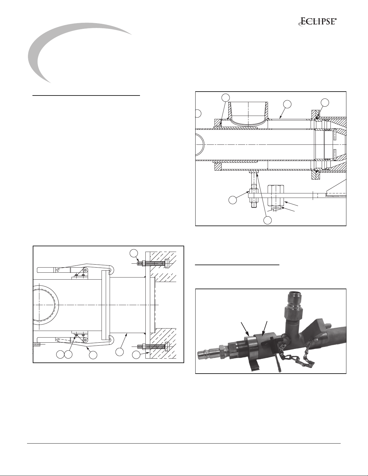
1. Install the burner mounting bracket (21) with gasket on the precombustor using four T-bolts, washers, and nuts (23). See Figure 3.1.
The T-bolts are only intended to secure the mounting
plate to the precombustor. The mounting plate must
be supported by the bolt assembly before installing
the burner.
2. Support the burner mounting bracket with a jack screw (A) and nuts (B). Make sure the horizontal plate is level. See Figure 3.2.
3. Briefly install the burner and flexible hoses into the precombustor to make sure the supply piping will permit easy burner installation.
23
Precombustor
17
5
6
26
A
B
25
Figure 3.2 PrimeFire 100 interior
NOTE: Whenever the burner is not in use, plug the burner
block with a high temperature fiber wool rolled blanket.
16
Adjusting the Burner Tip
The atomizing orifice in the burner oil tip is adjustable. Use
this procedure to adjust the burner tip.
3029
Figure 3.1 PrimeFire 100 exterior
20
21
22
locking
collar
1. Unscrew the locking collar. See Figure 3.3 above.
2. Rotate the oil boss to open or close the area of the atomizing orifice.
For startup, open the atomizing area by retracting the
oil tip (by rotating the oil boss) 1.5 mm (0.06 inch)
back.
o-rings
(inside)
Figure 3.3
7PrimeFire 100, Oil, Operating Instructions, Edition 9.12
Page 8

To set the initial oil tip position, set the oil tip flush with
the atomizing tip, then rotate the oil tube two full turns
back from flush. Two turns = 1.5 mm = 0.06 inch.
Installing the Burner
After the mounting hardware is installed and cooling
requirements are in place, use this procedure to install the
burner.
WARNING
■ Never operate this burner with the atomizing
oxygen orifice completely closed; this will cause it
to inject oil into the furnace without atomization,
which will cause a severe safety-related incident.
Notes on Burner Cooling
Use the following guidelines to make sure that the cooling
requirements for the burner are in place before installing
the burner.
WARNING
■ Combustion and atomizing oxygen cool the burner
and block, as well as supporting combustion. The
burner oxygen nozzles and fuel oil atomizing
assembly are made of a heat-resistant steel alloy,
but they can still be damaged if they are exposed
to furnace radiation without cooling oxygen flows
in the form of combustion and atomizing oxygen.
For oxy/oil firing, the fuel oil atomizing assembly is
extended well into the pre-combustor. It is roughly 63.5
mm (2.5 inches) back from the hot face of the precombustor. At this location, the atomizing assembly must
have atomizing oxygen flow for cooling purposes at all
times. Otherwise, it could suffer extensive heat damage or
meltdown.
The flow should be 10—23 Nm3/h (320 to 800 SCFH).
The combustion oxygen flow of about 27 Nm3/h (1,000
SCFH) must also be maintained, to keep the precombustor cool and free from furnace gases which could
deposit particulates/volatile matter on the precombustor
inner wall. In case of an emergency or power failure, pull
the entire burner body out to the pre-combustor opening
and plug the pre-combustor with a refractory plug or hightemperature fiber wool blanket.
Before installing the burner, have the combustion oxygen,
atomizing oxygen, and the fuel oil supply lines ready and
pressurized, so that within a few minutes of the burner
being placed in the block, a combustion oxygen flow of
about 27 Nm3/h (1000 SCFH) and atomizing oxygen of 10
Nm3/h (320 SCFH) can be started to provide cooling. The
only action required to start the oxygen flow at this point
should be to open the ball shutoff valve closest to the
burner.
NOTE: Before installing the burner, make sure that all
steps to achieve minimum oxygen flow through the burner
can be completed within less than five minutes after
burner installation.
WARNING
■ If the burner is not level, premature failure of the
precombustor is possible
1. Clamp the burner to the mounting section using the
clamping mechanism on the burner. Do not overtighten the clamps. Use only enough pressure to
ensure a firm seal of the burner to the preprecombustor. Insert the safety pins through the
clamping mechanism to lock it in place.
2. Connect the combustion oxygen, atomizing oxygen,
and the fuel oil hoses to the burner.
3. If the oil purge system is supplied, set the purge/oil
switch to Purge.
4. Open the combustion oxygen shutoff valve closest to
the burner to begin flowing oxygen at a rate of about
27 Nm3/Hr (1000 SCFH) through the burner to
provide cooling.
5. Open the atomizing oxygen shutoff valve closest to
the burner to begin flowing oxygen at a rate of about
10 Nm3/Hr (320 SCFH) through the burner to provide
cooling.
WARNING
■ Make sure the furnace is at a minimal temperature
for auto-ignition, 800°C (1472°F).
Firing the Burner with Oil
After installing the burner, use this procedure to fire the
burner using fuel oil.
NOTE: When firing oil, the oil tube tip must be retracted
into the atomizing nozzle 0.03" at a minimum. Issues may
occur if the oil tube is mounted in the incorrect position.
NOTE: If heavy (#6) oil is used, the oil temperature should
be adjusted to maintain an oil viscosity of about 20
centistokes (between 90—110 SSU) at the burner. Higher
oil viscosities are desirable, short of the oil flashing or the
small amount of water found in heavy oil turning to steam.
8PrimeFire 100, Oil, Operating Instructions, Edition 9.12
Page 9

Either of these occurences may cause unstable (pulsing)
burner performance.
1. Adjust the combustion oxygen flow to the lowest firing range of the burner (approximately 2000 SCFH per MMBtu of fuel input).
2. Adjust the atomizing oxygen pressure to 10 PSI for light oil, 20 PSI for heavy oil.
3. Open the fuel oil shutoff valve and adjust the flow rate to the minimum firing range of the burner.
NOTE: Observe the initial firing to ensure the flame is
centered in the precombustor and atomization is
sufficient.
4. After initial firing, combustion oxygen, atomizing
oxygen and fuel flows may be adjusted as desired.
When satisfactory atomizing oxygen flow is achieved,
the combustion oxygen can be adjusted to obtain the
total oxygen flow requirements for a given input
(approximately 2000 SCFH per MMBtu of fuel input).
NOTE: The exact ratio will vary depending on the calorific
value of the fuel and the actual percentage of oxygen into
the oxygen delivered.
Combustion oxygen velocity is typically set at the
maximum velocity position. After firing has been
established, combustion oxygen velocity can be adjusted
if necessary.
WARNING
■ Do not fire burner above or below capacity ranges.
This may cause the burner block to overheat.
Adjusting the Flame Shape
After initial firing, use this procedure to adjust the flame
shape.
1. Before attempting any flame shape adjustment with the burner adjustment screw, loosen the locking bolt. See Figure 3.2 above.
2. The burner nozzle can be adjusted to 51 mm (2 inches) in relation to the front end flange. To move the nozzle forward, turn the adjustment screw (item 60) clockwise. Each increment on the position rod represents 3 mm (1/8 inch) of nozzle travel.
NOTE: Typically, the nozzle is set to the Full In (maximum
velocity) position to operate the burner when firing oil. If
the position is set too far back, combustion may start
quickly and cause overheating of the block.
3. Tighten the locking bolt after the desired flame shape adjustment has been made.
Shutting Down and Removing the Burner
If a burner needs to be shut down temporarily, or for an
extended period, use the following procedure.
If a burner is to be taken offline temporarily and not
removed from the burner block, combustion and
atomizing must be supplied to the burner for cooling
purposes. If both the combustion and atomizing oxygen to
the burner are interrupted for more than 10 minutes, the
burner must be removed from the precombustor.
If a burner is to be taken offline for an extended time, use
the following procedure.
oil
boss
o-rings
(inside)
burner
adjustment screw
Figure 3.4
o-rings
(inside)
roll pin
locking
bolt
1. If the purge system is provided, purge the oil from the burner.
2. After the purge is complete, reduce atomizing oxygen, combustion oxygen, and fuel oil flow control valves to minimum.
3. Shut off the combustion oxygen, atomizing oxygen, and fuel oil shutoff valves closest to the burner.
4. Release the burner clamps from the mounting bracket. Remove the burner from the precombustor and mounting bracket.
5. Disconnect the combustion oxygen, atomizing oxygen, and fuel oil lines from the burner inlet.
6. Place a high-temperature fiber wool rolled blanket in the cavity of the precombustor to prevent hot furnace gases from escaping through the block.
9PrimeFire 100, Oil, Operating Instructions, Edition 9.12
Page 10

7. If the burner is not being used for an extended time, plug or cover the block opening with mullite or a bonded AZS block instead of fiber wool.
4. To view and inspect the intermediate tip, remove the roll pin from the burner adjustment screw and pull the tube out of the burner body. See Figure 3.2
8. If the burner is to be left out of service, close all service valves on the metering and control skid.
WARNING
■ Ensure that all lock-out and tag-out procedures are
in place according to your plant procedures.
NOTE: Whenever removing a burner from service, always
keep the oxygen-compatible components cleaned and
sealed. Hoses should be capped when not used. Burners
should be cleaned and stored in a sealed plastic bag.
Inspecting the Burner
Each shift should inspect the Primefire burners just as you
would inspect firing conditions in your present furnace.
Use these guidelines to inspect the burners, blocks, and
operation.
Recommended checks:
• Flame shape and appearance
• Burner block appearance
• Proper cooling effect on burner and block
• Combustion oxygen flow
• Atomizing oxygen flow and pressure
• Fuel oil flow and pressure
Obvious changes from the standard should be
investigated. If needed, fuel should be shut off with
combustion and atomizing oxygen set to a minimum while
the situation is investigated.
Maintaining the Burner
Under normal operating conditions, the Primefire oxy-oil
burner should need little attention. If you need to remove
and inspect a burner, use this procedure.
1. Follow the steps above under Burner Shutdown and Removal.
2. The oxygen tip can be viewed and inspected. See Figure 1.2 on page 4.
3. To remove the atomizing assembly:
NOTE: The o-rings are used for sealing between the oil
and atomizing oxygen tubes, the intermediate and
atomizing oxygen tubes, and the intermediate and
combustion oxygen tubes. See Figure 1.1, 3.1 and 3.2.
Use only Eclipse supplied halocarbon grease on the orings to ensure oxygen compatibility. Also make sure the
surfaces that mate with the o-rings are kept clean and are
not scratched. A damaged surface can cause a leak.
Cleaning the Burner Parts
After the burner is disassembled, use the following
procedure to clean the parts.
1. Using compressed air and cleaning solvent, clean the oil tube tip.
Handle all tips carefully to prevent damage.
2. Wipe the oil tube clean.
3. Clean the atomizing oxygen tube with appropriate oxygen cleaning solvents. Wipe the tube clean when done.
4. Clean all oxygen-compatible components and wipe clean when done; reassemble the burner by reversing the disassembly instructions under Burner Maintenance.
When reassembling the burner:
• Examine all o-rings and apply fresh halocarbon
grease.
• Use the centering lugs for the oil tube, atomizing
oxygen tube, and intermediate tube to ensure the
respective tube is in the proper centered location for
efficient mixing.
NOTE: Be careful not to damage the sealing surface on
the atomizing tube assembly. A damaged surface can
cause a leak.
• Verify the oil tip is in the correct position, and is
locked in position.
Always store the burner in a sealed plastic bag. This will
ensure that the burner is oxygen-compatible and ready to
fire.
a.Remove the ball lock pin.
b.Gently pull the atomizing assembly out of the
burner body.
3. The oil tip can be removed by loosening the oil boss at the rear of the tube, then pulling the oil tube out.
10PrimeFire 100, Oil, Operating Instructions, Edition 9.12
Page 11

11PrimeFire 100, Oil, Operating Instructions, Edition 9.12
Page 12

Appendix
Conversion Factors
Metric to English
From To Multiply By
actual cubic meter/h (am³/h) actual cubic foot/h (acfh) 35.31
normal cubic meter/h (Nm³/h) standard cubic foot /h (scfh) 38.04
degrees Celsius (°C) degrees Fahrenheit (°F) (°C x 9/5) + 32
kilogram (kg) pound (lb) 2.205
kilowatt (kW) Btu/h 3415
meter (m) foot (ft) 3.281
millibar (mbar) inches water column ("w.c.) 0.402
millibar (mbar) pounds/sq in (psi)
millimeter (mm) inch (in) 3.94 x 10
MJ/Nm³ Btu/ft³ (standard) 26.86
Metric to Metric
14.5 x 10
-3
-2
English to Metric
actual cubic foot/h (acfh) actual cubic meter/h (am³/h) 2.832 x 10
standard cubic foot /h (scfh) normal cubic meter/h (Nm³/h) 2.629 x 10
degrees Fahrenheit (°F) degrees Celsius (°C) (°F - 32) x 5/9
inches water column ("w.c.) millibar (mbar) 2.489
From To Multiply By
kiloPascals (kPa) millibar (mbar) 10
meter (m) millimeter (mm) 1000
millibar (mbar) kiloPascals (kPa) 0.1
millimeter (mm) meter (m) 0.001
From To Multiply By
pound (lb) kilogram (kg) 0.454
Btu/h kilowatt (kW) 0.293 x 10
foot (ft) meter (m) 0.3048
pounds/sq in (psi) millibar (mbar) 68.95
inch (in) millimeter (mm) 25.4
Btu/ft³ (standard) MJ/Nm³ 37.2 x 10⁻³
-2
-2
-3
i
Page 13

Notes
ii
Page 14

© Eclipse, Inc. All Rights Reserved
 Loading...