

Page 1
Eclipse Linnox Burners
Models Straight ULE and Tee ULE
Operating Instructions Edition 6.15
Version 1
Page 2
Copyright
This is the safety alert symbol. It is used to alert you to potential personal
injurt hazards. Obey all safety messages that follow this symbol to avoid
possible injury or death.
Indicates a hazardous situation which, if not avoided, will result in death
or serious injury.
Indicates a hazardous situation which, if not avoided, could result in
death or serious injury.
Indicates a hazardous situation which, if not avoided, could result in
minor or moderate injury.
Is used to address practices not related to personal injury.
Indicates an important part of text. Read thoroughly.
NOTE
NOTICE
CAUTION
WARNING
Copyright 2011 by Eclipse, inc. All rights reserved
worldwide. This publication is protected by federal
regulation and shall not be copied, distributed,
transmitted, transcribed or translated into any human or
computer language, in any form or by any means, to any
third parties, without the express written consent of
Eclipse, inc.
Disclaimer Notice
In accordance with the manufacturer’s policy of continual
product improvement, the product presented in this
brochure is subject to change without notice or obligation.
The material in this manual is believed adequate for the
intended use of the product. If the product is used for
purposes other than those specified herein, confirmation
of validity and suitability must be obtained. Eclipse
warrants that the product itself does not infringe upon any
United States patents. No further warranty is expressed or
implied.
Liability & Warranty
We have made every effort to make this manual as
accurate and complete as possible. Should you find errors
or omissions, please bring them to our attention so that we
may correct them. In this way we hope to improve our
product documentation for the benefit of our customers.
Please send your corrections and comments to our
Technical Documentation Specialist.
It must be understood that Eclipse’s liability for its product,
whether due to breach of warranty, negligence, strict
liability, or otherwise is limited to the furnishing of
replacement parts and Eclipse will not be liable for any
other injury, loss, damage or expenses, whether direct or
consequential, including but not limited to loss of use,
income, or damage to material arising in connection with
the sale, installation, use of, inability to use, or the repair
or replacement of Eclipse’s products.
Any operation expressly prohibited in this manual, any
adjustment, or assembly procedures not recommended or
authorized in these instructions shall void the warranty.
Document Conventions
There are several special symbols in this document. You
must know their meaning and importance.
The explanation of these symbols follows below. Please
read it thoroughly.
How To Get Help
If you need help, contact your local Eclipse
representative. You can also contact Eclipse at:
1665 Elmwood Rd.
Rockford, Illinois 61103 U.S.A.
Phone: 815-877-3031
Fax: 815-877-3336
http://www.eclipsenet.com
Please have the information on the product label available
when contacting the factory so we may better serve you.
www.eclipsenet.com
Product Name
Item #
S/N
DD MMM YYYY
2
Page 3

Table of Contents
1 Introduction............................................................................................................................ 4
Product Description .............................................................................................................. 4
Audience .............................................................................................................................. 4
Purpose................................................................................................................................ 4
Linnox Straight ULE and Tee ULE Documents .................................................................... 4
Related Documents.............................................................................................................. 4
2 Safety...................................................................................................................................... 6
Introduction .......................................................................................................................... 6
Safety Warnings ................................................................................................................... 6
Capabilities........................................................................................................................... 6
Operator Training ................................................................................................................. 6
Replacement Parts...............................................................................................................6
3 Installation.............................................................................................................................. 7
Introduction .......................................................................................................................... 6
Handling ............................................................................................................................... 6
Storage................................................................................................................................. 6
Position of Components ....................................................................................................... 6
Approval of Components...................................................................................................... 6
Checklist Before Installation ................................................................................................. 7
General Installation Conditions ............................................................................................ 7
Burner Mounting................................................................................................................... 7
Flame Sensor Installation..................................................................................................... 7
Gas Piping............................................................................................................................ 7
Air Piping .............................................................................................................................. 10
Electrical Supply................................................................................................................... 10
Profile Plates ........................................................................................................................ 10
Burner Support..................................................................................................................... 10
Checklist After Installation ....................................................................................................10
4 Adjustment, Start and Stop .................................................................................................. 12
Introduction .......................................................................................................................... 12
Checklist Before Burner Start-Up ......................................................................................... 12
Adjustment Procedure.......................................................................................................... 13
Start Procedure .................................................................................................................... 14
Stop Procedure .................................................................................................................... 17
5 Maintenance and Troubleshooting ...................................................................................... 18
Introduction .......................................................................................................................... 18
Maintenance......................................................................................................................... 18
Troubleshooting.................................................................................................................... 20
Appendix ................................................................................................................................... i
Notes.......................................................................................................................................... ii
3Linnox, V1, Operating Instructions, Edition 6.15
Page 4

4Linnox, V1, Operating Instructions, Edition 6.15
Page 5

5Linnox, V1, Operating Instructions, Edition 6.15
Page 6
Introduction
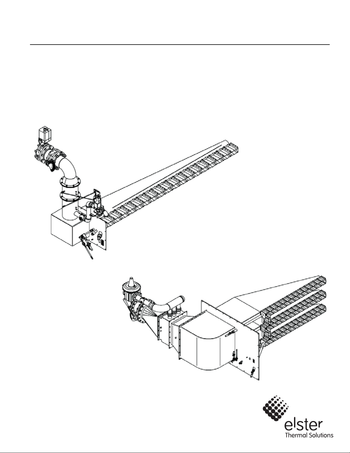
Product Description
The Linnox is a line model burner designed for
applications where a maximum linear heat distribution is
required.
The Linnox burner is a pre-mix type burner, designed for
direct-air heating applications where the lowest
achievable NO
Linnox combustion is based on high excess air, pre-mix
combustion to keep the flame temperatures low. At the
same time, the burner geometry establishes an internal
recirculating flame pattern. These two factors result in
ultra low NO
range while maintaining extremely stable combustion.
This burner can be easily configured for many different
capacities by choosing from a wide range of burner
modules each 300 mm in length.
The Linnox is designed to provide:
• Reliable operation
• Simple adjustments
• Efficient ratio controlled combustion
• Burner modules varying from 90 to 2700 kBtu/h
(26 to 791 kW per 300 mm).
Purpose
The purpose of this manual is to ensure a safe, effective
and trouble-free installation.
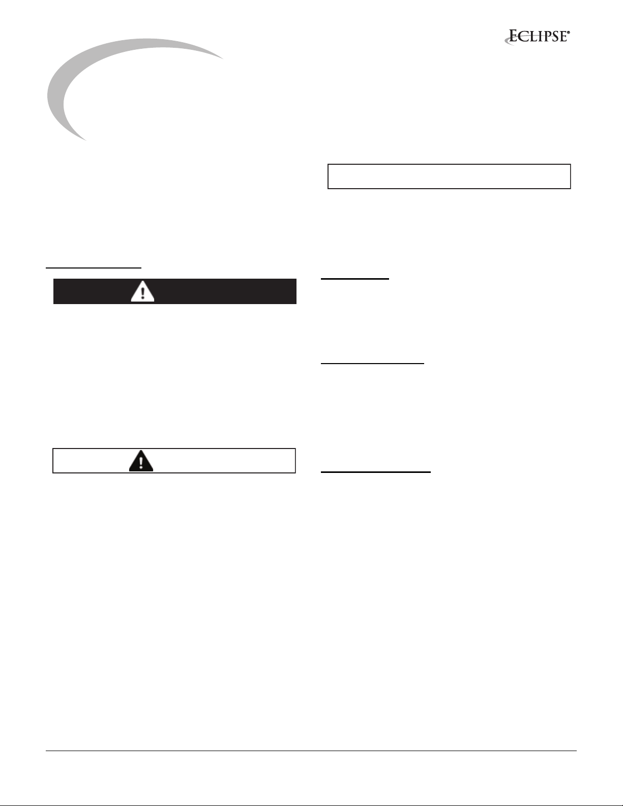
Figure 1.1 Linnox Straight ULE Burner
and CO levels are required.
x
and CO emissions across the turndown
x
1
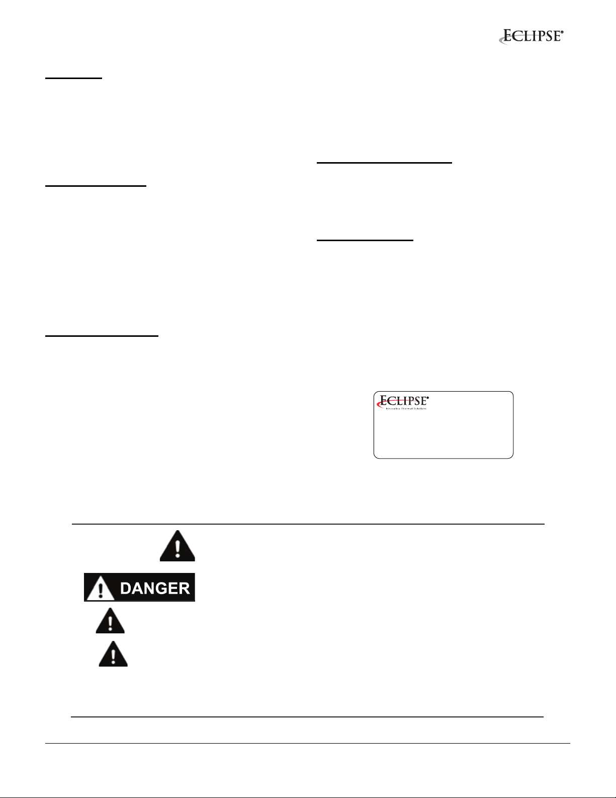
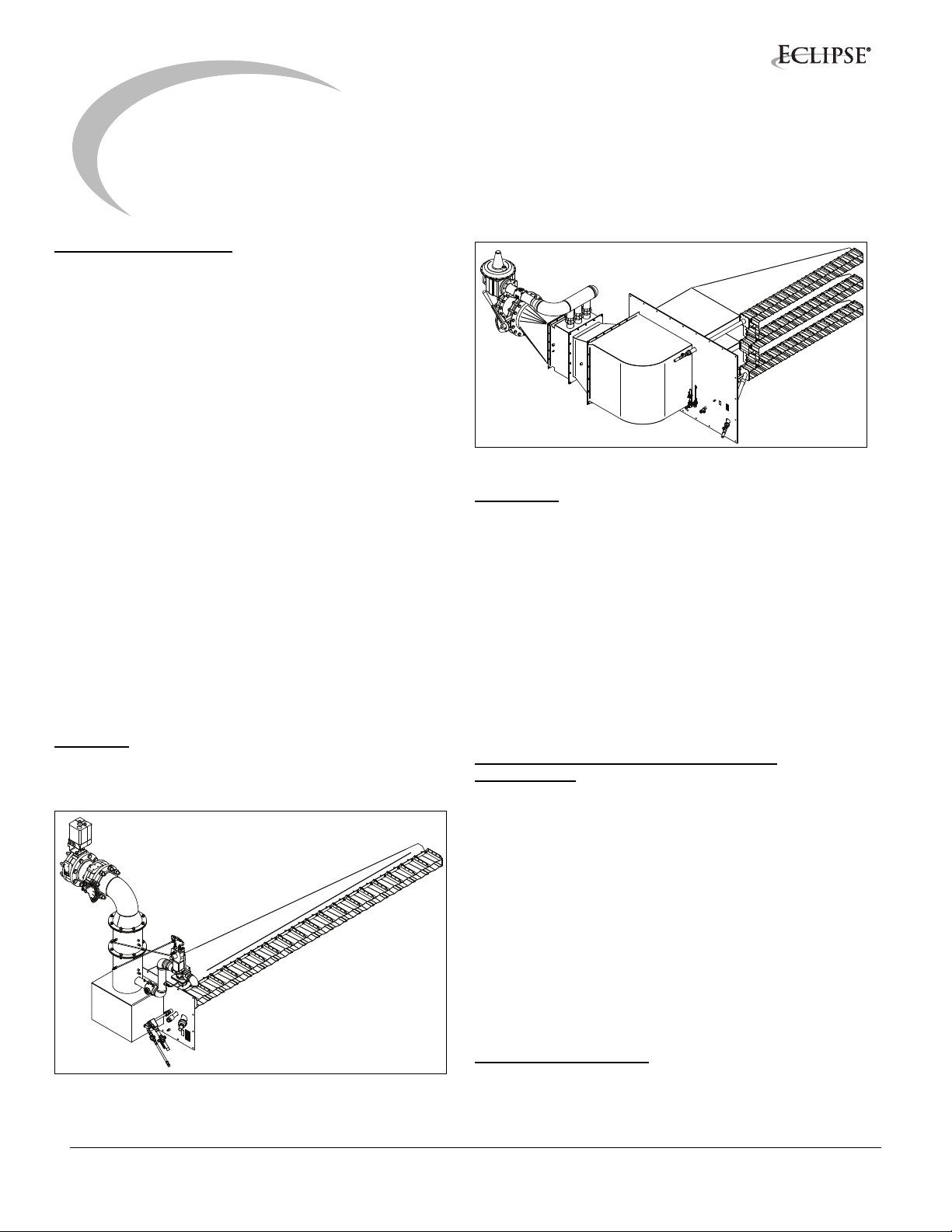
Figure 1.2 Linnox Tee ULE Burner
Audience
This manual has been written for personnel already
familiar with all aspects of pre-mix burners.
These aspects include:
• Installation
• Use
• Maintenance
• Safety
The audience is expected to be qualified and have
experience with this type of equipment and its working
environment.
Linnox Straight ULE and Tee ULE Documents
Design Guide 159
• Used with Datasheets to design the burner system
Datasheet Series 159
• Required to complete design and selection
Installation Guide 159
• This document
Worksheet 159
• Required to provide application information to
Eclipse Engineering
Spare Parts List Series 159
• Recommended replacement part information
Related Documents
• EFE 825 (Combustion Engineering Guide)
• Eclipse Bulletins and Information Guides: 610, 710,
720, 730, 742, 744, 760, 930
4Linnox, V1, Operating Instructions, Edition 6.15
Page 7
Safety
WARNING
Important notices which help provide safe burner
operation will be found in this section. To avoid personal
injury and damage to the property or facility, the following
warnings must be observed. All involved personnel should
read this entire manual carefully before attempting to start
or operate this system. If any part of the information in this
manual is not understood, contact Eclipse before
continuing.
Safety Warnings
DANGER
■ The burners, described herein, are designed to mix
fuel with air and burn the resulting mixture. All fuel
burning devices are capable of producing fires and
explosions if improperly applied, installed,
adjusted, controlled or maintained.
■ Do not bypass any safety feature; fire or explosion
could result.
■ Never try to light a burner if it shows signs of
damage or malfunction.
2
NOTICE
■ This manual provides information regarding the
use of these burners for their specific design
purpose. Do not deviate from any instructions or
application limits described herein without written
approval from Eclipse.
Capabilities
Only qualified personnel, with sufficient mechanical
aptitude and experience with combustion equipment,
should adjust, maintain or troubleshoot any mechanical or
electrical part of this system. Contact Eclipse for any
needed commissioning assistance.
Operator Training
The best safety precaution is an alert and trained
operator. Train new operators thoroughly and have them
demonstrate an adequate understanding of the
equipment and its operation. A regular retraining schedule
should be administered to ensure operators maintain a
high degree of proficiency. Contact Eclipse for any needed
site-specific training.
■ The burner and duct sections are likely to have
HOT surfaces. Always wear the appropriate
protective equipment when approaching the
burner.
■ Eclipse products are designed to minimize the use
of materials that contain crystalline silica.
Examples of these chemicals are: respirable
crystalline silica from bricks, cement or other
masonry products and respirable refractory
ceramic fibers from insulating blankets, boards, or
gaskets. Despite these efforts, dust created by
sanding, sawing, grinding, cutting and other
construction activities could release crystalline
silica. Crystalline silica is known to cause cancer,
and health risks from the exposure to these
chemicals vary depending on the frequency and
length of exposure to these chemicals. To reduce
the risk, limit exposure to these chemicals, work in
a well-ventilated area and wear approved personal
protective safety equipment for these chemicals.
Replacement Parts
Order replacement parts from Eclipse only. All Eclipse
approved valves or switches should carry UL, FM, CSA,
CGA and/or CE approval where applicable.
5
Page 8

Installation
3
Introduction
This section provides guidance for correct installation of
Eclipse Linnox burners.
NOTE: Information in Datasheet Series 159 may be
necessary to complete some of the installation
procedures.
WARNING
■ Only qualified, competent personnel with
combustion system experience are allowed to
install, adjust and maintain the burner.
■ All installation work must be carried out in
compliance with jurisdictional codes.
Handling
• Inspect the burner and its components ensuring that
all components are clean and free of damage.
• Use the appropriate support equipment when lifting
the burner and its components.
• Protect the burner and its components from the
weather, damage, dirt and moisture.
Storage
• Make sure the burner and its components are clean
and free of damage.
• Store the burner and its components in a cool,
clean, dry room.
• After you have made sure everything is present and
in good condition, keep the components in the
original package as long as possible.
Position of Components
The position and amount of components are determined
by three factors: burner design, system design and
chosen control method. All three factors are considered in
“System Design” chapter of the Linnox Design Guide 159.
Use the information in that chapter to build your system.
Approval of Components
Limit Controls & Safety Equipment
All limit controls and safety equipment must comply with
all applicable local codes and/or standards and must be
listed for combustion safety by an independent testing
agency. Typical application examples include:
• American: NFPA 86 with listing marks from UL, FM,
CSA
• European: EN 746-2 with CE mark from TuV,
Gastec, Advantica
Electrical Wiring
All electrical wiring must comply with all applicable local
codes and/or standards such as:
• NFPA Standard 70
• IEC60364
• CSA C22
• BS7671
Piping
All gas piping must comply with all applicable local codes
and/or standards such as:
• NFPA Standard 54
• ANSI Z223
• EN 746-2
The gas piping must meet jurisdictional codes.
Where to Get the Standards:
The NFPA Standards are available from:
National Fire Protection Agency
Batterymarch Park
Quincy, MA 02269
www.nfpa.org
The ANSI Standards are available from:
American National Standard Institute
1430 Broadway
New York, NY 10018
www.ansi.org
The UL Standards are available from:
333 Pfingsten Road
Northbrook, IL 60062
www.ul.com
6Linnox, V1, Operating Instructions, Edition 6.15
Page 9

The FM Standards are available from:
1151 Boston-Providence Turnpike
PO Box 9102
Norwood, MA 02062
www.fmglobal.com/approvals
Information on the EN standards and where to get
them is available from:
Comité Européen de Normalisation
Stassartstraat 36
B-1050 Brussels
Phone: +32-25196811
Fax: +32-25196819
www.cen.eu
Comité Européen de Normalisation Electronique
Stassartstraat 36
B-1050 Brussels
Phone: +32-25196871
Fax: +32-25196919
www.cenelec.org
Checklist Before Installation
Air Supply
To admit fresh combustion air from outdoors, provide an
opening in the room of at least one square inch per 4,000
Btu/h (6 cm
materials in the air, supply the burner with clean air from
an uncontaminated area, and always provide a sufficient
air filtering system.
Exhaust
Do not allow exhaust fumes to accumulate in the work
area. Provide some positive means for exhausting fumes
from the furnace and the building.
Access
Make sure to install the burners in such a way that you can
gain easy access for inspection and maintenance.
Environment
Make sure the burner operating environment matches the
original operating specifications. Check the following
items:
• Voltage, frequency and stability of the electrical
• Type and supply pressure of the fuel
• Availability of enough fresh, clean combustion air
• Adequate oxygen concentration for combustion on
• Humidity, altitude and temperature of the air
• Presence of damaging corrosive gases in the air
• Prevent direct exposure to water
2
per 1 kW). If there are corrosive fumes or
power
the process gases
General Installation Conditions
Perform the following audits before installing the burner:
• Remove all dirt, dust, and other particles from inside
the burner air/gas piping, and avoid further soiling
during piping and accessory installation.
• Check that there are no obstructions in the burner
duct or in the supply piping connections.
Electrical
Install the high-voltage ignition transformer (as applicable)
as close to the burner as possible.
Burner Mounting
Make sure the chamber wall is strong enough to support
the weight of the burner. If necessary, reinforce the
mounting area.
Mount burner to process duct using customer supplied
bolts, nuts, and lockwashers.
The burner mounting plate is provided with:
• a peep sight for pilot flame observation
• a pressure tap for measuring process pressure
• a pipe nipple to mount the UV scanner and the UV
scanner cooling air connection
• or without an insulation box (refer to assembly
drawing)
Flame Sensor Installation
Install the UV scanner onto the 3/4” NPT pipe nipple
extending from the outside of the burner mounting plate.
The UV scanner must be connected to the flame safety for
that burner. Cooling air piping must be supplied to the tee
connection located between the UV scanner and the
mounting plate.
CAUTION
■ The burner flame shields can reach a temperature
of 1650
temperature upstream from the burner.
Measurements should be taken to prevent
excessive thermal load on the process ducting.
Gas Piping
Care should be taken to ensure that the incoming gas pipe
is adequately sized for the necessary gas flow and burner
pressure (See Datasheets 159-1 and 159-2 for gas
pressure requirements).
Gas piping not supplied with the burner must be
supported independently of the burner.
°F (900°C) at 480°F (250°C) process
7Linnox, V1, Operating Instructions, Edition 6.15
Page 10

Figure 3.1. 8:1 Ratio Regulators Impulse Line Piping
Figure 3.2. 10:1 Ratio Regulators Impulse Line Piping
8Linnox, V1, Operating Instructions, Edition 6.15
Page 11

WARNING NOTICE
■ Gas inlet pressures must stay within the specified
range. Pressure above the specificed range can
damage the ratio regulator.
■ Pressure below the specified gas inlet pressure
range can impair the ability of the ratio regulator to
control the gas flow.
Air Piping
Combustion air piping between the blower and the burner
air connection point must be supported independently of
the burner.
Electrical Supply
The burner must be controlled via a sequence
programmer, approved according to jurisdictional codes.
■ Wiring to the burner must be in accordance with
jurisdictional wiring standards. It is vital that the
live and neutral wires are connected correctly as
reversal could present a hazard. Also the
grounding must be checked to ensure a good
connection. (Wiring diagrams are provided only
for a burner system that incorporates an Eclipse
furnished control panel.)
■ GAS PIPEWORK MUST NOT BE USED FOR
GROUNDING PURPOSES.
■ If burner control signals are supplied via a flame
safeguard control panel provided by others,
Eclipse Combustion shall not accept any
responsibility for incorrect interfacing.
Profile Plates
Profile plates need to be installed to obtain the proper
process air axial velocity as specified in Datasheets
159-1 and 159-2. See Figure 3.4 for suggested profile
plate locations. Profile plates must be supported
independently from the burner.
Burner Support
Burners with rows over four feet long must be supported,
but not constrained, on the manifold at the end opposite
the pilot in order to prevent excessive stress caused by
thermal expansion. Reference Figure 3.3 for manifold
support location.
Figure 3.3.
9Linnox, V1, Operating Instructions, Edition 6.15
Page 12

Checklist After Installation
Profile Plate
Profile Plate
Side View
Front View
1/2”
gap
To verify proper system installation, perform the following
audits:
1. Make sure there are no leaks in the gas piping or the air piping.
2. Make sure all the components of the flame monitoring
system and the control system are properly installed.
This includes making sure that all the switches are
installed in the correct locations and that all the wiring,
pressure lines, and impulse lines are properly
connected.
3. Make sure all interlocks and safety components are installed and working properly.
4. Make sure the required air and gas pressures are available. Verify that the blower wheel rotation is correct. If it is incorrect, have a qualified electrician rewire the blower to reverse its rotation.
5. Make sure all components of the spark ignition system are installed and functioning properly.
6. Make sure the burner control system operates under interrupted pilot timing; i.e. the controller should shut the pilot off after the trial for ignition period.
Figure 3.4. Suggested profile plate locations
10Linnox, V1, Operating Instructions, Edition 6.15
Page 13

Adjustment, Start
and Stop
4
Introduction
In this chapter you will find instructions on how to adjust,
start and stop a Linnox burner.
DANGER
■ The burners covered by this guide are designed to
burn a mixture of gas and air. All gas burning
devices are capable of producing fires and
explosions if improperly applied, installed,
adjusted, controlled or maintained.
■ Do not bypass any safety feature. This can cause
fires and explosions.
■ Obey the safety precautions in the “Safety”
chapter of this document, and read this chapter
thoroughly before starting your system.
■ Never try to light a burner if it shows signs of
damage or malfunction.
NOTE: Adjustment requires two guides: Installation Guide
159 and Datasheet 159. This chapter refers to the
component information explained in Design Guide 159.
Preparation
1. Ensure all installation work has been completed in compliance with jurisdictional codes.
2. Ensure all gas supply pipework has been purged of air in compliance with jurisdictional codes.
3. Ensure all required utilities are available.
4. Ensure all pre-checks have been completed in compliance with jurisdictional codes.
5. Ensure a digital or “U”-tube manometer for pressure measurement is available.
6. Set the low gas pressure switch to 20% below the lowest pressure given in the "Main Gas Inlet Pressure" range specified in DataSheet 159.
7. Set the high gas pressure switch to 20% above the highest pressure given in the "Main Gas Inlet Pressure" range specified in DataSheet 159.
8. Verify the location of the pilot tube with respect to the end shield prior to installing the burner. Reference Figure 4.1 for proper pilot location.
Checklist Before Burner Start-up
Preliminary Installation Checks
• Verify that the process control setpoints are correct.
• Check that the main control panel switch is ON.
• Verify that the process air and combustion air
blowers are operating correctly.
• Confirm that the burner, the system interlocks, the
customer interlocks, and the safeties are in working
order.
• Open the main manual gas supply valve.
• Verify that the main gas inlet pressure is correct.
12Linnox, V1, Operating Instructions, Edition 6.15
Page 14

Figure 4.1. Pilot Location - All dimensions shown in inches (mm)
0.39
(10.0)
Pilot
Location
Duct Spacing
Duct Spacing
7.9 (200)
11.8 (300)
15.8 (400)
19.7 (500)
23.6 (600)
27.6 (700)
31.5 (800)
35.4 (900)
39.4 (1000)
Pilot Location
7.4 (188)
3.5 (88)
7.4 (188)
3.5 (88)
7.4 (188)
3.5 (88)
7.4 (188)
3.5 (88)
7.4 (188)
NOTE: Eclipse authorized personnel should perform the
initial start of all Eclipse burners.
Adjustment Procedure
DANGER
Become familiar with burner methods before attempting to
make adjustments.
Follow these steps to adjust the Linnox system for the first
time:
Step 1: Dry Run
1. Ensure that the process air blower is running.
2. Close all the manual and automatic gas valves.
3. Initiate the electrical supply to start the operating
sequence. The combustion air blower will start running.
If the sequence is operating correctly, the system will
run through to the point of ignition, the safety shut-off
valves will open and, in absence of a flame, the system
will proceed to a lockout condition.
■ If simulated limits or simulated flame failure do not
shut down the fuel system within the required
response time, immediately correct the problem
before proceeding.
Step 2: Combustion Air Check
NOTE: On multiple burner systems with a central
combustion air blower, one should remember that the
combustion air pressure will change depending on the
total air demand. If one burner is adjusted, it is advised to
set the combustion air of all other burners to at least 50%
of the maximum capacity if the burners are not in
operation. This will prevent flame failures or inability to
reach the high-fire capacity when the installation is
switched to normal operation.
NOTE: Start all process air blowers that affect chamber
pressure.
13Linnox, V1, Operating Instructions, Edition 6.15
Page 15

Low-Fire and High-Fire Air Adjustment
Top Screw
Handle
(Shown in
Open Position)
Adjusting Screw
(Clockwise for less pilot gas,
Counterclockwise for more pilot gas)
Procedure:
1. Start the combustion air blower.
2. Drive control motor to low-fire position (activate the manual switch or lock first).
3. Measure air differential pressure (Tap A to Tap D).
4. Adjust low-fire air if necessary.
NOTE: The slot at the end of the BV (air damper) shaft
indicates the position of the BV. The BV is closed when
the shaft slot is perpendicular to the direction of air flow
through the BV. For adjustment of the BV, adjust the lever
mechanism.
5. Verify ignition position
a.Drive the combustion air control valve to ignition
position, 30% open.
b.Adjust air pressure if necessary.
The pilot flame should be approximately 1 - 2 inches
(25 - 51 mm) long and be contained within the flame
shields in a mixed blue and yellow color. If the flame is too
weak or too big, adjust the pilot flame to the pressures
indicated in Datasheets 159-1 and 159-2. Adjustment of
the adjustable port pilot gas cock is outlined in Figure 4.2.
Pilot flame appearance also depends on the start position
of the combustion air control valve and process air
conditions.
6. Verify high-fire air
a.Drive combustion air control valve to high fire, fully
open.
b.Adjust high fire air if necessary.
7. Return the combustion air control valve to low-fire position.
8. Close the pressure taps
Start Procedure
Step 3: StartUp Procedure
NOTE: The maximum gas pressure allowed at the inlet of
the adjustable port pilot gas cock is 1/2 psig. Do not
exceed this pressure.
1. Check the pre-setting of the adjustment valves.
2. Switch the combustion air control valve to “automatic”.
3. Open all gas manual isolating ball valves.
Figure 4.2. Adjustable Port Pilot Gas Cock
After the trial for ignition period determined by local
regulations, the safety shut-off valves will open, and the
main flame will ignite. A clear blue line flame will appear
at the burner base. The appearance will vary for the
different capacity ratings of the burner elements.
If the burner does not light the first time, it will be
necessary to reset the sequence and follow the start
procedure again.
5. If the burner did not ignite after several attempts:
a.Verify that the air has been purged from the main and
pilot gas piping.
b.If the pilot flame does not appear, adjust the gas and
air pressures to the values listed in the datasheet.
c.If the flame appears at ignition, but the main burner
does not light, turn the bias adjusting screw of the gas
ratio regulator one turn clockwise to increase gas flow
and try to ignite the burner again.
4. Initiate the burner management system to start the operating sequence. The combustion air control valve will be driven to the start position after which the ignition will take place.
d.Repeat steps b and c several times until the burner
ignites. If the burner does not ignite, follow the
guidelines in Section 7 of this document,
“Maintenance and Troubleshooting”.
14Linnox, V1, Operating Instructions, Edition 6.15
Page 16

Low-Fire Settings
6. Set the system control to stay at low fire during and after the ignition sequence, or set the control motor to manual.
Eventually, the static gas pressure at the mixer can be
used as a pre-setting for the burner.
NOTE: A visual check of the flame is important to ensure
the correct burner adjustment.
Ensure the combustion air control valve stops at low fire.
7. Adjust ratio regulator bias adjustment for lowest gas flow that maintains a stable flame signal:
- clockwise for more fuel
- counterclockwise for less fuel
Ensure that the lowest flame signals are stable.
At low fire the gas differential pressure across the mixer
will be too low, for a reliable reading.
NOTE: If the recirculating process air is cold, < 212°F
(100°C), the burner elements will not glow or will partially
glow.
NOTE: If the recirculating process air is hot, > 390°F
(200°C), the burner elements will glow.
NOTE: The visual appearance of the low-fire flame should
be clear blue with some of the burner elements glowing.
Lambda 1.8
Lambda 1.8 Lambda 1.4 Lambda 1.1
Lambda 1.4 Lambda 1.1
Figure 4.3. Low Fire Flame Appearance
15Linnox, V1, Operating Instructions, Edition 6.15
Page 17

When operating at high fire, if the flame becomes too rich,
carefully close the manual gas adjustment valve until the
flame starts blowing off. Open the valve again to pull the
flame back in. The flame should look like the center image
in Figure 4.3. The flame shields may be slightly red and
the flame may extend beyond these shields.
High-Fire Settings
NOTE: A visual check of the flame is important to ensure
the correct burner adjustment. The flame will be sharp
blue-white with a slightly orange glowing tip. The length of
this tip depends on the burner capacity rating.
NOTE: If the flame tip is dominantly orange, the burner
may be set too gas rich. Refer to the “Troubleshooting”
section of this document.
8. Set the burner to high fire:
a. Check the differential air pressure against the values
given in Datasheets 159-1 and 159-2.
b. Adjust the corresponding gas pressure with the
adjustment butterfly valve.
Fasten the lock screw, by tightening gently, at the
adjustment butterfly valve after finishing adjustment.
Lambda 1.8 Lambda 1.4 Lambda 1.1
Figure 4.4. High Fire Flame Appearance
NOTE: The burner flame shields are allowed to glow red
hot depending on the burner capacity rating and the
process temperatures.
9. If the setting of adjustment valve has been changed, repeat Steps 6 and 7 to check and readjust the low-fire setting.
A flame that is too lean (Lambda > 1.4) will produce too
much CO and have a fluctuating flame signal. A rich flame
(Lambda < 1.4) will create too much NOx and burner parts
will overheat
CAUTION
■ Adjusting the burner too gas rich will shorten the
lifetime of the burner elements and flame shields.
Therefore, have a qualified Eclipse engineer adjust
and regularly check the burner settings.
Step 4: Operation Inspections
1. Simulate a flame-out condition by closing the manual
inlet ball valve. Run the ignition cycle again.
2. Have a qualified technician check high gas pressure switch for correct operation.
3. Have a qualified technician check the combustion air pressure switch for correct operation.
4. Measure and record the gas and air differential pressure and flame signal at low and high fire for future reference.
DANGER
■ If simulated limits or simulated flame failures do
not shut down the fuel system within the required
response time, immediately correct the problem
before proceeding.
16Linnox, V1, Operating Instructions, Edition 6.15
Page 18

CAUTION
■ Do not turn the combustion air blower off until the
chamber temperature is below 250°F (120°C). This
will prevent hot gases from flowing back through
the burner, which would cause damage to the
burner.
Stop Procedure
1. Shut off the load, or the control system demand switch
to initiate shutdown.
2. Shut off main and pilot manual gas supply valves.
3. Drive combustion air valve to high-fire position.
4. Leave the combustion air at high fire until the
combustion chamber is cooled to under 250°F (120°C);
once cooled, shut off the combustion air fan. Higher
shutdown temperatures may be allowed depending on
the system design. Consult Eclipse for more
information.
5. Shut down all manual valves as required.
All initial settings shall be documented in a proper manner
and kept as the initial commissioning data for future
reference.
17Linnox, V1, Operating Instructions, Edition 6.15
Page 19

Maintenance and
Troubleshooting
5
Introduction
This section is divided into two parts. The first part
describes the maintenance procedures. The second part
identifies problems that may occur and gives advice on
how to solve these problems.
Maintenance
Preventative maintenance is the key to a reliable, safe
and efficient system. The following are suggested
guidelines for periodic maintenance. Burners in severe
environments or operational conditions should be
checked more frequently.
NOTE: The monthly and yearly lists are an average
interval. If your environment is dirty, the intervals may be
shorter. Check with the local authorities that have
jurisdiction over recommended maintenance schedules.
CAUTION
■ Turn off power to burner and controls before
proceeding with burner inspection.
■ Turn off the main gas supply.
7. Check if the burner module fastening nuts are tight.
8. Check the burner surroundings for signs of excessive corrosion or deformation due to thermal overload or moisture. Repair or replace insulation or thermal protection shields if necessary.
Every Three Months
1. Visually check all components for damage.
2. Check manual shut-off valve for correct operation.
3. Visually check all cables and connectors for damage and tightness.
4. Visually check the condition of the blower inlet filter; replace if necessary.
Every Six Months
1. Check burner and mixer unit for leakage, damage or deterioration. Those parts in contact with the process environment must be inspected thoroughly.
2. Check the flame shields, burner elements and all joints for wear and damage.
One Month after Startup
1. Check and compare burner adjustments with the original recorded settings. Correct the settings if they are outside the specified tolerance range.
2. Check and clean or replace the gas filter if necessary.
3. Check all gas piping and connections for leakage. Leaks must be repaired immediately.
4. Check tightness of all bolted/screwed joints.
5. Check burner and mixer unit for leakage, damage or deterioration. Those parts in contact with the process environment, must be inspected thoroughly.
6. Check the flame shields, burner elements and all joints for wear and damage.
3. Check if the burner element fastening nuts are tight.
4. Check and clean or replace the igniter.
5. Check the flame quality, verifying both visually and via the air-fuel ratio that the flame is neither too lean or too rich.
It is important that the flame at low fire is stable and
doesn’t blow off, which happens when the mixture is too
lean (has too much excess air).
If the mixture is too rich (not enough excess air), the parts
in the burner modules will begin to glow immediately and
possibly overheat. Simultaneously, the NOx emissions
will increase. An incorrectly tuned flame will also result in
a low flame signal and could create a flame failure.
18Linnox, V1, Operating Instructions, Edition 6.15
Page 20

Yearly Checklist
1. Check and compare burner adjustments with the original recorded settings. Correct the settings if they are outside the specified tolerance range.
2. Check for correct operation.
3. Check and clean or replace the gas filter if necessary.
7. Check the interlocks by simulating fault conditions. Resolve all flame safety problems before restarting the burner.
8. Check the direct burner surroundings for signs of excessive corrosion or deformation due to thermal overload or moisture. Repair or replace insulation or thermal protection shields if necessary.
As per Supplier’s Instructions
4. Leak test shut-off valves.
5. Check all gas piping and connections for leakage. Leaks must be repaired immediately.
6. Check tightness of all bolted/screwed joints.
1. Replace the UV scanner within the time frame as specified by the supplier.
Depending on the Circumstances
1. Check and clean or replace the combustion air filter if necessary.
2. Clean the burner. Flame shields and burner modules must not be covered with dust or dirt.
Troubleshooting
Troubleshooting of electrical circuits should be done by qualified plant electricians, technicians or engineers experienced
in all facets of this type of combustion equipment.
Problem Possible Cause Solution
Cannot initiate startup
sequence.
Burner sequence starts but
locks out before ignition.
Air pressure switch has not made contact. Check air pressure switch adjustment.
Check air filter. Check for correct rotation of
the blower wheel.
External interlock failure. Check all external interlocks.
High gas pressure switch has activated. Check pressure switch settings.
Low gas pressure switch has activated. Check pressure switch settings.
Malfunction of the flame safeguard.
No power to the flame safeguard.
Combustion air fault: Blower failure. Check blower and remedy the fault.
Combustion air fault: Blocked blower inlet
or filter.
Combustion air fault: Pressure switch
failure.
Combustion air fault: 3-way solenoid valve
failure.
Have a qualified electrician troubleshoot
and correct the problem.
Clean inlet. Clean or replace filter.
Check operation of the pressure switch and
replace it if necessary.
Check solenoid valve. Replace coil if
necessary.
19Linnox, V1, Operating Instructions, Edition 6.15
Page 21

Problem Possible Cause Solution
Startup sequence runs but
burner does not light.
No ignition: No power to the ignition
transformer.
Check the output from the flame safeguard
and the wiring between the flame safeguard
and the ignition transformer.
No ignition: Open circuit between the
ignition transformer and the ignition
Repair or replace wiring to the ignition
electrode.
electrode.
Pilot flame appears, but main
burner does not ignite.
Burner lights and then goes
to lock-out.
No ignition: Ignition electrode needs
Clean the ignition electrode.
cleaning.
No ignition: The ignition electrode is not
properly grounded to the burner.
No ignition: Ignition electrode insulator is
broken.
Not enough gas: The pilot gas valve is not
opening.
Clean the threads on the ignition electrode
and burner.
Inspect the ignition electrode and replace if
broken.
Check wiring between the flame safeguard
and the pilot gas valve. Check the output
from the flame safeguard.
Not enough gas: The pilot gas flow is
Open adjusting valve one turn.
adjusted too low.
Not enough gas: Second shut-off valve not
opening.
Check the wiring between the flame
safeguard and the second shut-off valve.
Check output from the flame safeguard.
Open manual ball valve. Replace the shutoff valve if necessary.
Not enough gas: low-fire setting too low or
Adjust ratio controller bias.
too high.
Not enough gas: High-fire adjusting valve
Open adjusting valve to correct pre-setting.
closed.
No flame signal: Dirty UV scanner lens. Inspect and clean UV scanner.
The high-fire flame is orange
or yellow. Burner parts are
excessively hot.
The low-fire flame is orange
or yellow. Burner elements
are glowing.
The low-fire flame is weak
and unstable. Flame signals
are low.
Gas/air ratio out of adjustment: Gas mixer
Clean nozzle.
nozzle blocked.
Gas/air ratio out of adjustment: Blocked
Check/clean loading line.
loading line.
Gas/air ratio out of adjustment: Air mixing
Clean gas/air mixer.
plate blocked.
Gas pressure too high: High-fire adjusting
Check burner data for correct pressures
valve too far open.
Gas pressure too high: Gas ratio regulator
Replace gas ratio regulator.
failure.
Too much gas. Adjust ratio regulator. If necessary check
the low fire fuel/air adjustments.
Insufficient gas flow to the burner or too
much air.
Adjust the low-fire setting on the ratio
regulator.
Not enough air. Adjust combustion air valve. Clean or
replace filter. Check blower rotation.
20Linnox, V1, Operating Instructions, Edition 6.15
Page 22

Problem Possible Cause Solution
High-fire flame is weak and
blue, flame signals are low.
Burner does not reach its
specified capacity.
Insufficient gas flow to the burner. Check burner gas adjustment and readjust.
Gas nozzle blocked.
Not enough air: Air butterfly valve does not
Check air control motor limit settings.
open.
Flame has irregular pattern
showing holes.
Not enough air: Blower is running in
Check and correct blower wiring.
reverse.
Not enough air: Inlet or filter blocked. Clean inlet or filter. Replace filter if
necessary.
Not enough air: Burner elements blocked. Clean burner elements.
Not enough gas (air is ok): Gas pressure
Check for sufficient gas pressure.
into the ratio regulator is too low.
Burner elements blocked. Damaged
elements.
Clean burner elements. Replace burner
module.
21Linnox, V1, Operating Instructions, Edition 6.15
Page 23

Appendix
Conversion Factors
Metric to English
From To Multiply By
actual cubic meter/h (am³/h) actual cubic foot/h (acfh) 35.31
normal cubic meter/h (Nm³/h) standard cubic foot /h (scfh) 38.04
degrees Celsius (°C) degrees Fahrenheit (°F) (°C x 9/5) + 32
kilogram (kg) pound (lb) 2.205
kilowatt (kW) Btu/h 3415
meter (m) foot (ft) 3.281
millibar (mbar) inches water column ("w.c.) 0.402
millibar (mbar) pounds/sq in (psi)
millimeter (mm) inch (in) 3.94 x 10
MJ/Nm³ Btu/ft³ (standard) 26.86
Metric to Metric
14.5 x 10
-3
-2
English to Metric
actual cubic foot/h (acfh) actual cubic meter/h (am³/h) 2.832 x 10
standard cubic foot /h (scfh) normal cubic meter/h (Nm³/h) 2.629 x 10
degrees Fahrenheit (°F) degrees Celsius (°C) (°F - 32) x 5/9
inches water column ("w.c.) millibar (mbar) 2.489
From To Multiply By
kiloPascals (kPa) millibar (mbar) 10
meter (m) millimeter (mm) 1000
millibar (mbar) kiloPascals (kPa) 0.1
millimeter (mm) meter (m) 0.001
From To Multiply By
pound (lb) kilogram (kg) 0.454
Btu/h kilowatt (kW) 0.293 x 10
foot (ft) meter (m) 0.3048
pounds/sq in (psi) millibar (mbar) 68.95
inch (in) millimeter (mm) 25.4
Btu/ft³ (standard) MJ/Nm³ 37.2 x 10
-2
-2
-3
-3
i
Page 24

Notes
iv
Page 25

© Eclipse, Inc. All Rights Reserved
 Loading...