

Page 1
Edition 12.09
F
NL
I
E
SK
D GB F NL I SK
03250886/002
➔ www.docuthek.com
Operating instructions
Diaphragm gas meters
BK-G1.6 to BK-G25 and
BK-G1.6T to BK-G25T
Translation from the German
© 2008 – 2010 Elster GmbH
Contents
Diaphragm gas meters
BK-G1.6 to BK-G25 and
BK-G1.6T to BK-G25T . . . . . . . . . . . . . . . . . . . 1
Contents . . . . . . . . . . . . . . . . . . . . . . . . . . . . . . 1
Safety. . . . . . . . . . . . . . . . . . . . . . . . . . . . . . . . . 1
Checking the usage . . . . . . . . . . . . . . . . . . . . . 2
Diaphragm gas meters BK-G1.6 to G25 . . . . . . 2
Type code. . . . . . . . . . . . . . . . . . . . . . . . . . . . . . 2
Part designations. . . . . . . . . . . . . . . . . . . . . . . . 2
Type label/Index plate. . . . . . . . . . . . . . . . . . . . . 2
Installation . . . . . . . . . . . . . . . . . . . . . . . . . . . . 2
Tightness test. . . . . . . . . . . . . . . . . . . . . . . . . .
Commissioning. . . . . . . . . . . . . . . . . . . . . . . . .
Interface for mechanical index . . . . . . . . . . . . . . 3
Interface for Absolute ENCODER index . . . . . . . 3
Diaphragm gas meters BK with integrated
“Smart Valve” . . . . . . . . . . . . . . . . . . . . . . . . . . . 3
“Smart Valve” valve function . . . . . . . . . . . . . . . . 4
Maintenance/Removal. . . . . . . . . . . . . . . . . . . 4
Technical data. . . . . . . . . . . . . . . . . . . . . . . . . . 4
Diaphragm gas meters BK. . . . . . . . . . . . . . . . . 4
Diaphragm gas meters BK with explosion
protection . . . . . . . . . . . . . . . . . . . . . . . . . . . . . 4
Diaphragm gas meters BK with integrated
“Smart Valve” . . . . . . . . . . . . . . . . . . . . . . . . . . . 4
Declaration of conformity . . . . . . . . . . . . . . . . 5
Diaphragm gas meters BK. . . . . . . . . . . . . . . . . 5
Diaphragm gas meters BK with explosion
protection . . . . . . . . . . . . . . . . . . . . . . . . . . . . . 5
Contact . . . . . . . . . . . . . . . . . . . . . . . . . . . . . . . 6
Safety
Please read and keep in a safe place
Please read through these instructions
carefully before installing or operating. Follow-
ing the installation, pass the instructions on to the
operator. These instructions can also be found at
www.docuthek.com.
Explanation of symbols
• , 1 , 2 , ... = Action
= Instruction
Liability
We will not be held liable for damages resulting
from non-observance of the instructions and non-
compliant use.
Safety instructions
Information that is relevant for safety is indicated in
the instructions as follows:
DANGER
Indicates potentially fatal situations.
WARNING
Indicates possible danger to life and limb.
CAUTION
Indicates possible material damage.
All interventions may only be carried out by qualified
gas technicians. Electrical interventions may only be
carried out by qualified electricians.
Conversion, spare parts
All technical changes are prohibited. Only use OEM
spare parts.
Transport
Diaphragm gas meters are always to be transported
in the upright position. On receipt of the product,
check that the delivery is complete (see Part desig-
nations). Report any transport damage immediately.
Storage
Diaphragm gas meters are always to be stored in the
upright position and in a dry place. Ambient tempera-
ture: see Technical data.
GB
GB-1
Page 2
F
NL
I
E
SK
Checking the usage
m
3
,
-
BK-Gx
12 345 6 78
DE-07-MI002-PTB001
002545632734 1 imp =^ 0,01 m
3
class 1,5
NG-47001BM0443 DIN EN 1359:2007
Q
max
Q
min
M09 0102
Diaphragm gas meters BK-G1.6 to G25
Residential or commercial diaphragm gas meters
BK for recording gas consumption values for natural
gas, town gas, propane and butane, gases of the
first to third families pursuant to DIN EN 437:2003
(DVGW Code of Practice G260). If used for internal
measurements which are not subject to statutory
testing, the gas meter is also suitable for hydrogen,
nitrogen, air and inert gases.
Potentially explosive atmosphere
Diaphragm gas meters that are labelled with and
GB
(see sticker next to the index) are suitable for
operation in potentially explosive atmospheres of
Category 2G (Zone 1) of Class II 2G c IIB (TÜV 09
ATEX 554884X), see [Declaration of conformity – p.5].
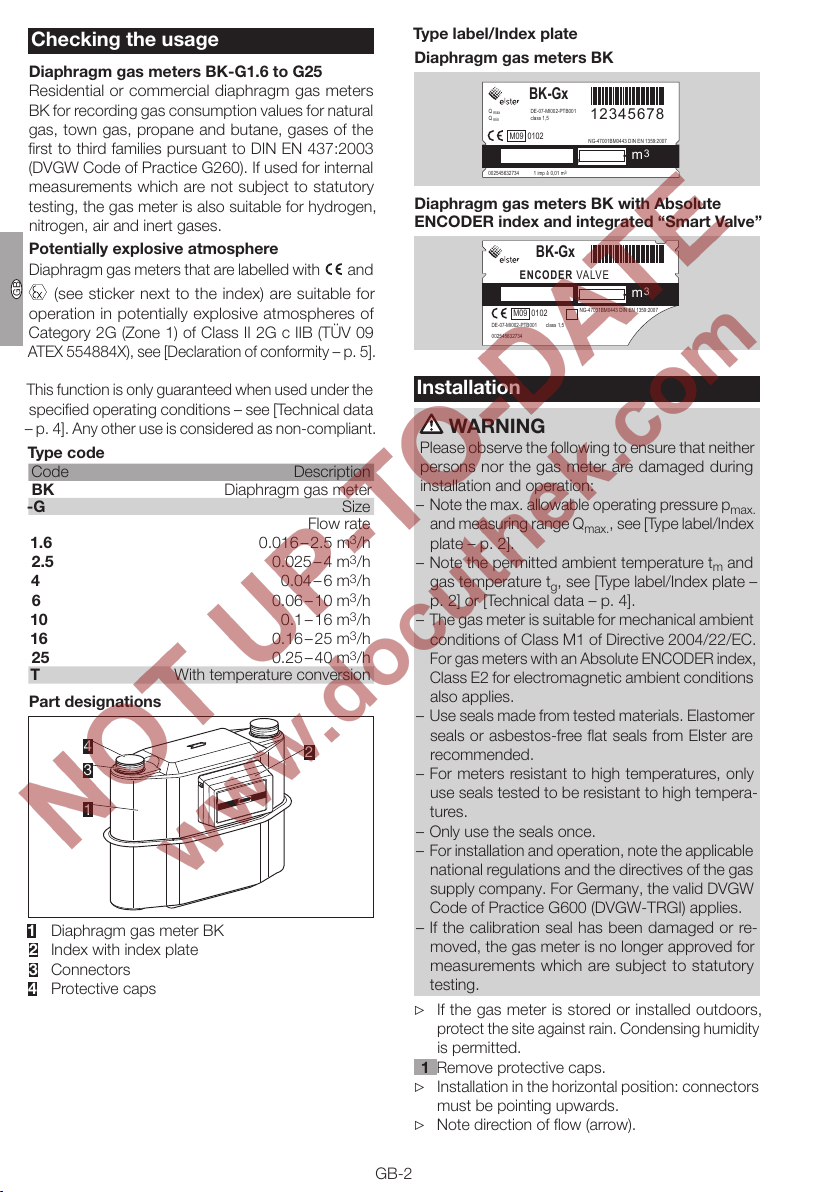
Type label/Index plate
Diaphragm gas meters BK
BK-Gx
DE-07-MI002-PTB001
Q
max
Q
min
M09 0102
002545632734 1 imp =^ 0,01 m
class 1,5
12 345 6 78
NG-47001BM0443 DIN EN 1359:2007
,
-
3
3
m
Diaphragm gas meters BK with Absolute
ENCODER index and integrated “Smart Valve”
BK-Gx
EN C OD ER VALV E
M09 0102
DE-07-MI002-PTB001
002545632734
,
NG-47001BM0443 DIN EN 1359:2007
class 1,5
3
m
-
This function is only guaranteed when used under the
specified operating conditions – see [Technical data
– p.4]. Any other use is considered as non-compliant.
Type code
Code Description
BK Diaphragm gas meter
-G Size
1.6
2.5
4
6
10
16
25
Flow rate
0.016 – 2.5 m
0.025 – 4 m3/h
0.04 – 6 m3/h
0.06 – 10 m3/h
0.1 – 16 m3/h
0.16 – 25 m3/h
0.25 – 40 m3/h
T With temperature conversion
Part designations
4
2
3
1
1 Diaphragm gas meter BK
2 Index with index plate
Connectors
4 Protective caps
Installation
WARNING
Please observe the following to ensure that neither
persons nor the gas meter are damaged during
installation and operation:
– Note the max. allowable operating pressure p
3
/h
and measuring range Q
plate – p.2].
, see [Type label/Index
max.
– Note the permitted ambient temperature tm and
gas temperature tg, see [Type label/Index plate –
p.2] or [Technical data – p.4].
– The gas meter is suitable for mechanical ambient
conditions of Class M1 of Directive 2004/22/EC.
For gas meters with an Absolute ENCODER index,
Class E2 for electromagnetic ambient conditions
also applies.
– Use seals made from tested materials. Elastomer
seals or asbestos-free flat seals from Elster are
recommended.
– For meters resistant to high temperatures, only
use seals tested to be resistant to high tempera-
tures.
– Only use the seals once.
– For installation and operation, note the applicable
national regulations and the directives of the gas
supply company. For Germany, the valid DVGW
Code of Practice G600 (DVGW-TRGI) applies.
– If the calibration seal has been damaged or re-
moved, the gas meter is no longer approved for
measurements which are subject to statutory
testing.
If the gas meter is stored or installed outdoors,
protect the site against rain. Condensing humidity
is permitted.
1 Remove protective caps.
Installation in the horizontal position: connectors
must be pointing upwards.
Note direction of flow (arrow).
max.
GB-2
Page 3

F
NL
I
E
SK
The gas meter must not be in contact with ma-
sonry or other parts.
Ensure that there is sufficient installation space.
Ensure unobstructed view of the index.
The seal faces on the screw unions must be clean
and damage-free.
For the compression of seals and the resulting
tightening torques for the screw unions, the seal
manufacturers’ specifications must be observed.
Tightening torques for the recommended flat seals
in conjunction with screw connectors pursuant to
DIN 3376-1 and 3376-2, see www.docuthek.com
Elster-Instromet Products Gas measuring
devices Diaphragm meters Ergänzung für
Betriebsanleitung BK, Verschraubungen und An-
zugsmomente für BK-G1,6 bis BK-G25 (Supple-
ment for BK operating instructions, Screw unions
and tightening torques for BK-G1.6 to BK-G25)
(D).
2 Install the gas meter free of mechanical stress.
The gas meter marked with must be included
in the equipotential bond when being installed in
a potentially explosive atmosphere, e.g. by con-
necting it to a grounded pipeline.
If a pulse sensor IN-Z6x is used for pulse tap-
ping on the gas meter marked with – see
Data sheet for pulse sensor IN-Z6x (D, GB)
www.docuthek.com Elster-Instromet Prod-
ucts Gas measuring devices Diaphragm
meters Pulse sensor IN-Z61 and the standard
EN 60079-14 (Explosive atmospheres).
Tightness test
Check the pipework for leaks prior to installation of
the gas meter, in case the pipework is tested with
a greater test pressure than the max. allowable
operating pressure p
erwise, the installed gas meter may be damaged.
If a valve is integrated in the diaphragm gas meter
BK, see [Type label/Index plate – p.2], this must
be opened for the tightness test.
Ensure the customer’s consumers are closed,
see [Diaphragm gas meters BK with integrated
“Smart Valve” – p.3].
1 Apply the test pressure slowly to the gas meter.
2
for the gas meter. Oth-
max.
Commissioning
Once the tightness test has been successfully com-
pleted, the gas meter is ready for operation.
Slowly open the manual valve.
Interface for mechanical index
For pulse tapping, the pulse sensor IN-Z6x can be
connected – see Data sheet for pulse sensor IN-Z6x
(D, GB) www.docuthek.com Elster-Instromet
Products Gas measuring devices Diaphragm
meters Pulse sensor IN-Z61.
Interface for Absolute ENCODER index
Interface description for gas meters with ENCODER in-
dex – see Specification (D, GB) www.docuthek.com
Elster-Instromet Products Gas measuring
devices Diaphragm meters Encoder index
Specification.
Diaphragm gas meters BK with integrated
“Smart Valve”
In the event that the diaphragm gas meter BK is fit-
ted with an integrated “Smart Valve”, see [Type label/
Index plate – p.2], the gas supply can be connected
or disconnected remotely.
WARNING
The network provider is responsible for the safe
remote shut-down and restart of the diaphragm
gas meter:
– The “Smart Valve” does not assume the safety
functions of a safety shut-off valve.
– Depending on national regulations, a limited and
technically safe gas flow rate in the customer’s
open consumer piping is allowed, see [Technical
data – p.4].
– Assessment of the non-critical gas flow rate with
regard to amount and duration, which occurs
when the valve is released, is to be defined by
the network provider.
– The minimum operating pressure on the inlet
must not be undershot, see [Technical data – p.4].
Otherwise, when the valve is released and if the
customer’s consumer piping is open at the same
time, the valve may be completely opened.
GB
After the tightness test, slowly vent the gas meter.
GB-3
Page 4

F
NL
I
E
SK
“Smart Valve” valve function
The “Smart Valve” is switched remotely by the data
management system. The valve first switches to the
“Released” position. From the “Released” position, the
valve automatically switches to the “Open” position,
if the downstream installation is tight.
Released
The “Smart Valve” opens an internal bypass and
releases a minimum gas flow into the customer’s
closed consumer piping. Pressure equalisation takes
place between the inlet and outlet side of the valve.
Open
Following pressure equalisation, the valve automati-
GB
cally opens by spring force and fully releases the
gas supply. If consumers of the customer are open,
pressure equalisation cannot occur and the valve
remains in the “Released” position and continues to
release only the minimum gas flow rate of the bypass.
Closed
The valve and the bypass are closed in the event of
remote shut-down.
All valve positions are kept de-energised.
Maintenance/Removal
Gas meters BK-G1.6 to 25 from Elster are mainte-
nance-free.
When used for custody transfer measurements,
recalibration must be carried out in accordance
with national Directives.
If the screw unions are loosened for maintenance
work or retesting, replace the seals.
After the gas meter has been removed, immedi-
ately close the connectors with protective caps,
in order to prevent an ingress of dirt particles.
Technical data
Diaphragm gas meters BK
Gas type: natural gas, town gas, propane and butane,
as gases of the first to third families pursuant to
DINEN 437:2003 (DVGW Code of Practice G260).
Max. allowable operating pressure p
[Type label/Index plate – p.2].
Max. allowable measuring range Q
[Type label/Index plate – p.2].
Max. allowable ambient temperature range tm, see
[Type label/Index plate – p.2].
Max. allowable storage temperature range: -25 to
+60°C.
Gas temperature tg, where the measuring error still
lies within the error limits set out in the Directive, see
[Type label/Index plate – p.2]. If no gas temperature
tg is specified on the index plate, tg = tm applies.
Diaphragm gas meters BK with explosion
protection
Max. allowable ambient temperature range tm/gas
temperature range tg: -20 to +55°C, for constraints
see [Type label/Index plate – p.2].
Diaphragm gas meters BK with integrated
“Smart Valve”
Opening time from closed to open/released state:
≤ 4 s,
closing time: ≤ 0.5 s.
Min. operating pressure: 17.5 mbar.
Allowed leakage flow in the customer’s piping:
valve released: max. 13 l/h at 35 mbar,
valve closed: max. 5 l/h.
, see
max.
min./Qmax.
, see
WARNING
A certain amount of gas may remain in the gas
meter. Taking into consideration the risk of explo-
sion, it is important to adopt safety measures, e.g.:
– Following removal of the gas meter, purge it thor-
oughly with inert gas.
– For transporting the gas meter with gas residue,
use a vehicle with an open or a ventilated loading
area.
GB-4
Page 5

F
NL
I
E
SK
Declaration of conformity
Diaphragm gas meters BK
We, the manufacturer, hereby declare that the prod-
uct BK, marked with No. DE-07-MI002-PTB001/DE-
07-MI002-PTB002, complies with the requirements
of the listed Directives and Standards.
Directives:
– 2004/22/EC (MID)
Standards:
– DIN EN 1359:2007 (EN 1359:1998 / A1:2006)
The relevant product corresponds to the tested type
sample.
The production is subject to the surveillance proce-
dure pursuant to 2004/22/EC, Annex D, Physika-
lisch-Technische Bundesanstalt (German National
Metrological Institute), Notified Body 0102.
Elster GmbH
Conformity with Directive 2004/22/EC is declared
by affixing the following markings:
0102
M...
After the “M”, the year of construction is given.
Diaphragm gas meters BK with explosion
protection
We, the manufacturer, hereby declare that the prod-
uct BK, marked with II 2G c IIB, complies with the
requirements of the listed Directives and Standards.
Directives:
– 94/9/EC
Standards:
– EN 13463-1:2001, EN 13463-5:2003 and
EN 1127-1:2007
The production is subject to the conformity assess-
ment procedure pursuant to 94/9/EC, Annex VIII,
Declaration of conformity No. TÜV 09 ATEX 554884 X,
TÜV NORD CERT GmbH, Notified Body 0044.
Elster GmbH
GB
= Marking of explosion protection
II = Equipment group ll for general industries (with
the exception of mines)
2G = Equipment category for gases, hazes and va-
pours for Zone 1
c = “Constructional safety” explosion protection
type
IIB = Explosion group
The unit is not a source of heat and therefore not
labelled with a temperature class.
Scan of the Declarations of conformity – see
www.docuthek.com
GB-5
Page 6

GB
F
NL
I
E
SK
Contact
Elster GmbH
Postfach 129, D-55248 Mainz-Kastel
Steinern Straße 19-21, D-55252 Mainz-Kastel
T +49 6134 605-0
F +49 6134 605-390
www.elster-instromet.com
Elster Metering Ltd.
Tollgate Business Park
Beaconside
Stafford, Staffordshire ST16 3HS
T +44 1785 275200
F +44 1785 275305
jeavons.info@gb.elster.com
GB-6
in the interests of progress.
We reserve the right to make technical modifications
 Loading...