

Page 1
F
NL
I
SK
050886/00 · Edition 0.
D GB F NL I SK
xx.xx Fx/ivd x.xxx
Operating instructions
➔ www.docuthek.com
Diaphragm gas meters
BK-G.6 to BK-G5
Translation from the German
© 2012 Elster GmbH
Contents
Contents
Diaphragm gas meters
BK-G.6 to BK-G5 .....................
Contents ..............................
Safety.................................
Checking the usage .....................
Diaphragm gas meters BK-G1.6 to G25 ......2
BK with integrated “Smart Valve”............2
Type code .............................2
Part designations ........................2
Type label/Index plate.....................2
ATEX identification .......................3
Installation ............................
Temperature test point ..................4
Connecting the pressure measuring line ...4
Tightness test ..........................4
Commissioning.........................5
BK-G..M with mechanical index.............5
BK-G..A with Absolute ENCODER indexAE1/Z6 . 5
BK-G..A with Absolute ENCODER AE2 and
communications module ACM..............5
BK-G..E with electronic index ..............5
Diaphragm gas meters BK with integrated valve 5
Maintenance/Removal...................6
Technical data .........................6
Declaration of conformity ................7
ATEX legend ...........................8
Contact ...............................8
Safety
Safety
Please read and keep in a safe place
Please read through these instructions
carefully before installing or operating. Following the
installation, pass the instructions on to the opera-
tor. This unit must be installed and commissioned
in accordance with the regulations in force. These
instructions can also be found at www.docuthek.com.
Explanation of symbols
• , , , ... = Action
▷ = Instruction
Liability
We will not be held liable for damages resulting
from non-observance of the instructions and non-
compliant use.
Safety instructions
Information that is relevant for safety is indicated in
the instructions as follows:
DANGER
Indicates potentially fatal situations.
WARNING
Indicates possible danger to life and limb.
CAUTION
Indicates possible material damage.
All interventions may only be carried out by qualified
gas technicians. Electrical interventions may only be
carried out by qualified electricians.
Conversion, spare parts
All technical changes are prohibited. Only use OEM
spare parts.
Transport
Diaphragm gas meters are always to be transported
in the upright position. On receipt of the product,
check that the delivery is complete (see Part desig-
nations). Report any transport damage immediately.
Storage
Diaphragm gas meters are always to be stored in the
upright position and in a dry place. Ambient tempera-
ture: see Technical data.
GB
GB-1
Page 2
F
NL
I
SK
Checking the usage
m
3
,
-
BK-G..M..
12345678
DE-07-MI002-PTB001
class 1,5
NG-47001BM0443 DIN EN 1359:2007
Q
max
Q
min
002545632734 1 imp =^ 0,01 m
3
M12 0102
Diaphragm gas meters BK-G.6 to G5
Residential or commercial diaphragm gas meters
BK for recording gas consumption values for natural
gas, town gas, propane and butane, as gases of the
first to third families pursuant to DIN EN 437:2003
(DVGW Code of Practice G260). If used for internal
measurements which are not subject to statutory
testing, the gas meter is also suitable for hydrogen,
nitrogen, air and inert gases.
BK with integrated “Smart Valve”
Not suitable for highly contaminated gases, e.g.
town gas.
GB
Potentially explosive atmosphere
Diaphragm gas meters that are labelled with and
(see sticker near the index) are suitable for opera-
tion in potentially explosive atmospheres, see page7
(Declaration of conformity).
This function is only guaranteed when used under the
specified operating conditions– see page6 (Technical
data). Any other use is considered as non-compliant.
Type code
Code Description
BK-G Diaphragm gas meter
.6
.5
4
6
0
6
5
M
C
A
E
B
T
Te
Chekker mechanical index
Absolute ENCODER index
Indication of volume at base conditions
Temperature conversion:
Flow rate
0.016 – 2.5 m
0.025 – 4 m3/h
0.04 – 6 m3/h
0.06 – 10 m3/h
0.1 – 16 m3/h
0.16 – 25 m3/h
0.25 – 40 m3/h
Mechanical index
Electronic index
mechanical
electronic
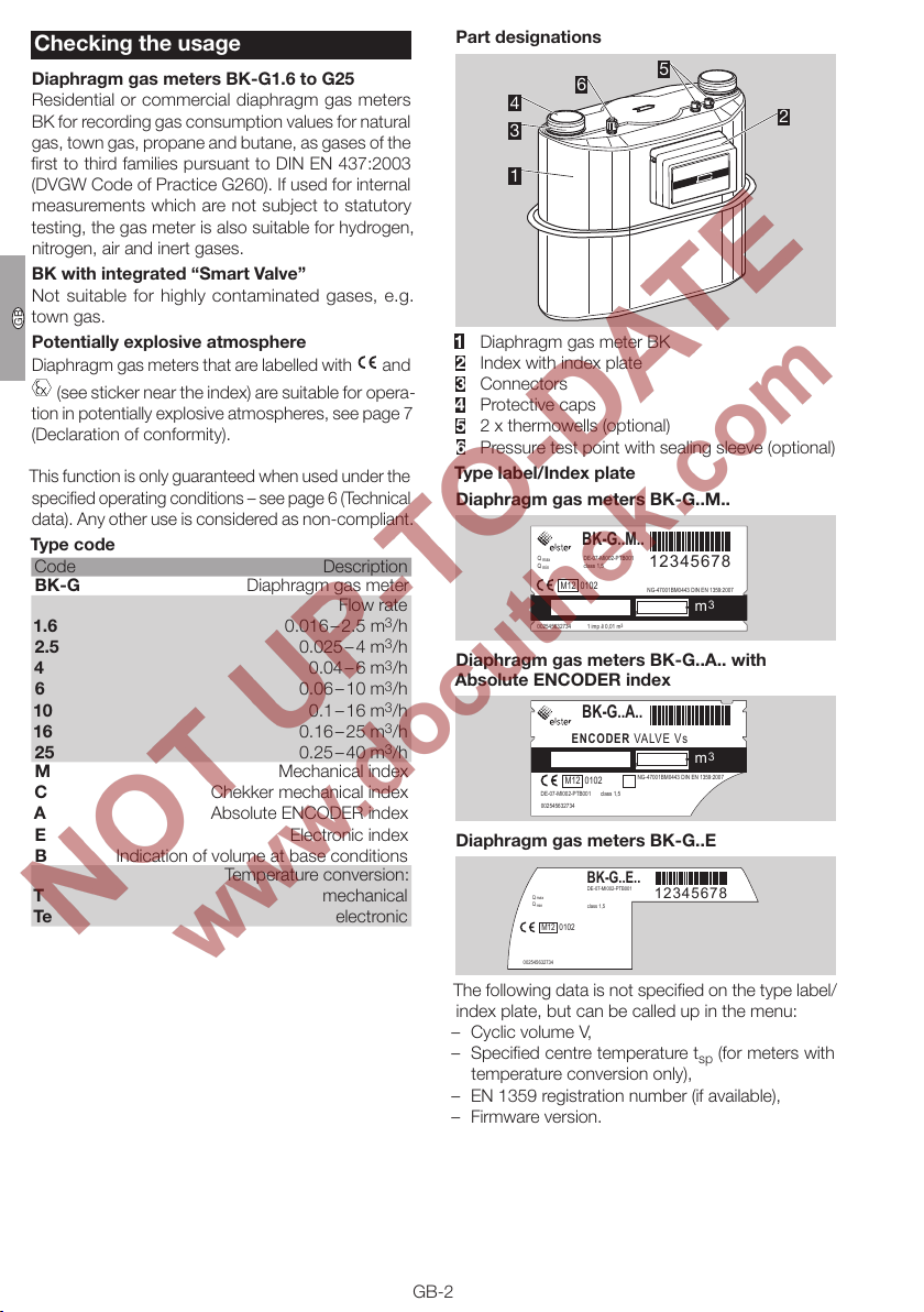
Part designations
6
4
3
5
2
1
Diaphragm gas meter BK
Index with index plate
Connectors
4 Protective caps
5 2 x thermowells (optional)
6 Pressure test point with sealing sleeve (optional)
Type label/Index plate
Diaphragm gas meters BK-G..M..
BK-G..M..
DE-07-MI002-PTB001
Q
max
Q
min
M12 0102
3
/h
002545632734 1 imp =^ 0,01 m
class 1,5
12345678
NG-47001BM0443 DIN EN 1359:2007
,
3
3
m
-
Diaphragm gas meters BK-G..A.. with
Absolute ENCODER index
BK-G..A..
ENCODER VALVE Vs
M12 0102
DE-07-MI002-PTB001
class 1,5
002545632734
,
NG-47001BM0443 DIN EN 1359:2007
3
m
-
Diaphragm gas meters BK-G..E
BK-G..E..
Q
max
Q
min
M12 0102
002545632734
DE-07-MI002-PTB001
class 1,5
12345678
The following data is not specified on the type label/
index plate, but can be called up in the menu:
– Cyclic volume V,
– Specified centre temperature tsp (for meters with
temperature conversion only),
– EN 1359 registration number (if available),
– Firmware version.
GB-2
Page 3
F
NL
I
SK
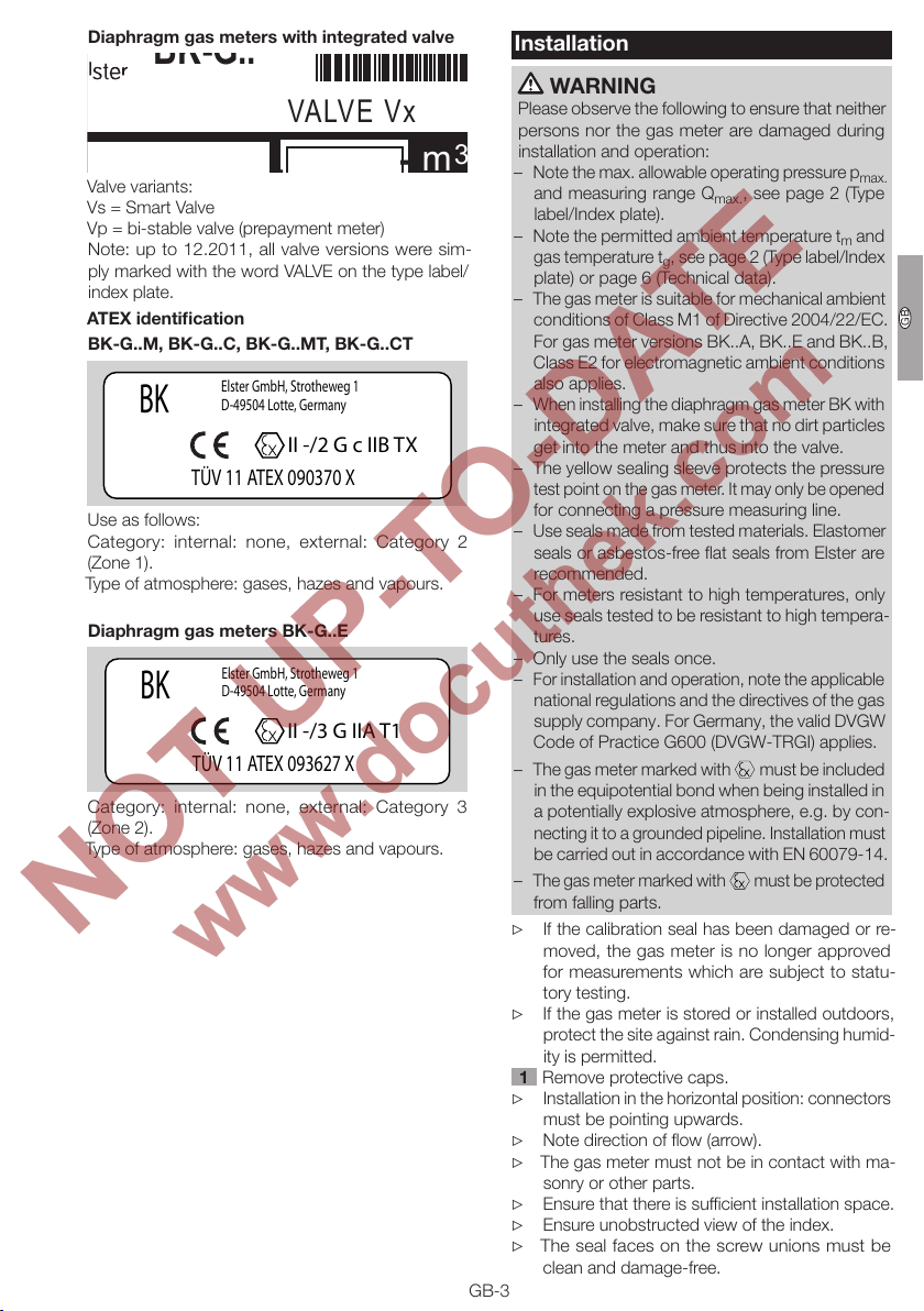
Diaphragm gas meters with integrated valve
BK-G..
m
3
VALVE Vx
Valve variants:
Vs = Smart Valve
Vp = bi-stable valve (prepayment meter)
Note: up to 12.2011, all valve versions were sim-
ply marked with the word VALVE on the type label/
index plate.
ATEX identification
BK-G..M, BK-G..C, BK-G..MT, BK-G..CT
Elster GmbH, Strotheweg 1
BK
D-49504 Lotte, Germany
II -/2 G c IIB TX
TÜV 11 ATEX 090370 X
Use as follows:
Category: internal: none, external: Category 2
(Zone1).
Type of atmosphere: gases, hazes and vapours.
Diaphragm gas meters BK-G..E
Elster GmbH, Strotheweg 1
BK
D-49504 Lotte, Germany
II -/3 G IIA T1
TÜV 11 ATEX 093627 X
Category: internal: none, external: Category 3
(Zone2).
Type of atmosphere: gases, hazes and vapours.
Installation
WARNING
Please observe the following to ensure that neither
persons nor the gas meter are damaged during
installation and operation:
– Note the max. allowable operating pressurep
and measuring rangeQ
label/Index plate).
– Note the permitted ambient temperaturetm and
gas temperaturetg, see page2 (Type label/Index
plate) or page 6 (Technical data).
– The gas meter is suitable for mechanical ambient
conditions of Class M1 of Directive 2004/22/EC.
For gas meter versions BK..A, BK..E and BK..B,
ClassE2 for electromagnetic ambient conditions
also applies.
– When installing the diaphragm gas meterBK with
integrated valve, make sure that no dirt particles
get into the meter and thus into the valve.
– The yellow sealing sleeve protects the pressure
test point on the gas meter. It may only be opened
for connecting a pressure measuring line.
– Use seals made from tested materials. Elastomer
seals or asbestos-free flat seals from Elster are
recommended.
– For meters resistant to high temperatures, only
use seals tested to be resistant to high tempera-
tures.
– Only use the seals once.
– For installation and operation, note the applicable
national regulations and the directives of the gas
supply company. For Germany, the valid DVGW
Code of Practice G600 (DVGW-TRGI) applies.
– The gas meter marked with
in the equipotential bond when being installed in
a potentially explosive atmosphere, e.g. by con-
necting it to a grounded pipeline. Installation must
be carried out in accordance with EN60079-14.
– The gas meter marked with must be protected
from falling parts.
▷ If the calibration seal has been damaged or re-
moved, the gas meter is no longer approved
for measurements which are subject to statu-
tory testing.
▷ If the gas meter is stored or installed outdoors,
protect the site against rain. Condensing humid-
ity is permitted.
Remove protective caps.
▷
Installation in the horizontal position: connectors
must be pointing upwards.
▷ Note direction of flow (arrow).
▷ The gas meter must not be in contact with ma-
sonry or other parts.
▷ Ensure that there is sufficient installation space.
▷ Ensure unobstructed view of the index.
▷
The seal faces on the screw unions must be
clean and damage-free.
GB-3
, see page2 (Type
max.
must be included
max.
GB
Page 4

F
NL
I
SK
▷ For the compression of seals and the resulting
1 2
1
2
3
4
5
1
6
7
2
3
4
5
tightening torques for the screw unions, the seal
manufacturers’ specifications must be observed.
Tightening torques for the recommended flat
seals in conjunction with screw connectors
pursuant to DIN 3376-1 and 3376-2, see
www.docuthek.com → Elster-Instromet → Prod-
ucts → Gas measuring devices → Diaphragm
meters → Ergänzung für Betriebsanleitung BK,
Verschraubungen und Anzugsmomente für
BK-G1,6 bis BK-G25 (Supplement for BK op-
erating instructions, Screw unions and tightening
torques for BK-G1.6 to BK-G25) (D).
Install the gas meter free of mechanical stress.
GB
▷
If a pulse sensor IN-Z6x is used for pulse tap-
ping on the gas meter marked with – see
Data sheet for pulse sensorIN-Z6x (D, GB)
www.docuthek.com→ Elster-Instromet→ Prod-
ucts→ Gas measuring devices→ Diaphragm
meters→ Pulse sensorIN-Z61 and the stand-
ardEN 60079-14 (Explosive atmospheres).
Temperature test point
▷
Temperature sensors can be inserted into the
thermowells for measuring the gas temperature
in the meter housing.
1
4
▷
Use corrosion-resistant, seamless precision
2
3
5
steel tube pursuant to DINEN10305-4 (exter-
nal diameter 6mm, material E235= 1.0308). For
other materials, use a suitable adapter and note
the Parker/EO recommendations.
▷ Install pipes free of mechanical stress.
6
7
8 Screw on the union nut by hand as far as it will
go.
▷
At the same time, press the end of the pipe firmly
against the stop.
9 Mark the position of the union nut and tighten
with about 1½ turns.
Secure each of the temperature sensors using
the capstan screw provided.
Connecting the pressure measuring line
WARNING
In order to ensure that the gas meter is tight:
– The pressure test nipple must not be twisted,
bent, or otherwise manipulated.
– When installing, always secure the pressure test
nipple using a suitable spanner.
▷
Functional safety and reliability are ensured only if
the material combination of the screw connector
and the pressure line are intermatched.
▷
Only use the olive and the attached union nut
supplied. The olive is secured to the sealing
sleeve.
▷
When re-ordering, use original Parker EO pro-
gressive ring fittings PSR/DPR.
▷ When re-installing, the union nut will be turned
to the original position and then further tightened
through approx. 30°.
Once the installation and tightness test are com-
plete, see page4 (Tightness test), protect the
pressure test point against external access with
the sealing sleeve and the seal.
Tightness test
▷
Check the pipework for leaks prior to installation
of the gas meter, in case the pipework is tested
with a greater test pressure than the max. al-
lowable operating pressure p
meter. Otherwise, the installed gas meter may
be damaged.
▷ If a valve is integrated in the diaphragm gas me-
terBK, see page2 (Type label/Index plate), this
must be opened for the tightness test.
▷ Ensure the customer’s consumers are closed.
GB-4
max.
for the gas
Page 5

F
NL
I
SK
Apply the test pressure slowly to the gas meter.
2
2
BK-G..E with electronic index
For further commissioning of diaphragm gas
meter BK-G..E with electronic index – see Elec-
tronic index operating instructions (D, GB) →
www.docuthek.com→ Elster-Instromet→ Prod-
ucts→ Gas measuring devices→ Diaphragm me-
ters→ Smart Metering.
▷ If a pressure measuring line has been retrofitted
to the diaphragm gas meter, check this connec-
tion for tightness.
3
Diaphragm gas meters BK with integrated valve
In the event that the diaphragm gas meterBK is fitted
with an integrated valve, see page3 (Diaphragm gas
meters with integrated valve), the gas supply can be
connected or disconnected remotely.
Unless otherwise agreed, the valve is open on delivery
GB
as standard.
4 After the tightness test, slowly vent the gas meter.
5 If a pressure measuring line has been retrofitted
to the diaphragm gas meter, protect the pressure
test point against external access with a sealing
sleeve and a seal.
WARNING
– The network provider is responsible for the safe
remote shut-down and restart of the diaphragm
gas meter.
– The integrated valve does not assume the func-
tions of a safety shut-off valve.
... with valve variantVp
Commissioning
Once the tightness test has been successfully com-
pleted, the gas meter is ready for operation.
▷ Slowly open the manual valve.
BK-G..M with mechanical index
For pulse tapping, the pulse sensorIN-Z6x can be
connected – see Data sheet for pulse sensorIN-Z6x
(D, GB)→ www.docuthek.com→ Elster-Instromet→
Products→ Gas measuring devices→ Diaphragm
meters→ Pulse sensorIN-Z61.
BK-G..A with Absolute ENCODER
indexAE/Z6
Interface description for gas meters with
ENCODER index– see Specification (D, GB)→
www.docuthek.com→ Elster-Instromet→ Prod-
ucts → Gas measuring devices → Diaphragm
meters→ Smart Metering→ SpecificationM-BUS
orSCR+.
BK-G..A with Absolute ENCODER AE and
communications module ACM
If the diaphragm gas meter BK-G..A is fitted with
communications module ACM – for further commis-
sioning see Communications module ACM M-BUS
WIRE, ACM SCR+ WIRE... or Communications mod-
ule ACM WAVE SYSTEM RF operating instructions (D,
GB, NL) → www.docuthek.com→ Elster-Instromet→
Products→ Gas measuring devices→ Diaphragm
meters→ Smart Metering.
▷
Should the diaphragm gas meter BK be ordered
with a valve Vp, but without control electronics to
be complemented by a third party, the technical
data of the control interface is to be requested
from Elster GmbH and observed.
The manufacturer of the control electronics is
▷
responsible for creating the conditions required
for safe operation of the valve. Instructions on
commissioning and operation are to be taken
from the operating instructions for the control
electronics.
... with valve variantVs (Smart Valve)
WARNING
– Depending on national regulations, a limited and
technically safe gas flow rate in the customer’s
open consumer piping is allowed, see page6
(Technical data).
– Assessment of the non-critical gas flow rate with
regard to amount and duration, which occurs
when the valve is released, is to be defined by
the network provider.
– The minimum operating pressure on the inlet
must not be undershot, see page6 (Technical
data). Otherwise, when the valve is released and
if the customer’s consumer piping is open at the
same time, the valve may be completely opened.
“Smart Valve” valve function
▷
The “Smart Valve” is switched remotely by
the data management system. The valve first
switches to the “Released” position. From the
“Released” position, the valve automatically
switches to the “Open” position, if the down-
stream installation is tight.
GB-5
Page 6

F
NL
I
SK
Released
▷
The “Smart Valve” opens an internal bypass and
releases a minimum gas flow into the customer’s
closed consumer piping. Pressure equalization
takes place between the inlet and outlet side
of the valve.
Open
▷ Following pressure equalization, the valve auto-
matically opens by spring force and fully releases
the gas supply. If consumers of the customer are
open, pressure equalization cannot occur and
the valve remains in the “Released” position and
continues to release only the minimum gas flow
rate of the bypass.
GB
Closed
▷
The valve and the bypass are closed in the event
of remote shut-down.
▷ All valve positions are kept de-energized.
Maintenance/Removal
Gas meters BK-G1.6 to 25 from Elster are mainte-
nance-free.
▷ When used for custody transfer measurements,
recalibration must be carried out in accordance
with national directives.
▷
If the screw unions are loosened for maintenance
work or retesting, replace the seals.
▷ After the gas meter has been removed, immedi-
ately close the connectors with protective caps,
in order to prevent an ingress of dirt particles.
WARNING
A certain amount of gas may remain in the gas
meter. Taking into consideration the risk of explo-
sion, it is important to adopt safety measures, e.g.:
– Following removal of the gas meter, purge it thor-
oughly with inert gas.
– For transporting the gas meter with gas residue,
use a vehicle with an open or a ventilated loading
area.
– The indexes must not be opened in an explosion-
hazard area even for maintenance and repair.
Opening of the service cover on the electronic
index, e.g. to change the battery, is permitted–
see operating instructions for “Electronic index
for diaphragm gas meters BK..E”.
Technical data
Diaphragm gas meters BK
Gas type: natural gas, town gas, propane and butane,
as gases of the first to third families pursuant to
DINEN437:2003 (DVGW Code of PracticeG260).
Max. allowable operating pressurep
label/index plate.
Max. allowable measuring rangeQ
type label/index plate.
Transitional flow rate Qt = 0.1 x Q
Max. allowable ambient temperature rangetm, see
type label/index plate.
Max. allowable storage temperature range:
-25 to +60°C.
Gas temperature tg, where the measuring error still
lies within the error limits set out in the Directive, see
type label/index plate. If no gas temperature tg is
specified on the index plate, tg = tm applies.
Cyclic volume V, see type label/index plate.
Base temperature tb (for meters with temperature
conversion only), see type label/index plate.
Specified centre temperature tsp (for meters with tem-
perature conversion only), see type label/index plate.
For BK..E.., the cyclic volume V and the specified
centre temperaturetsp are not stated on the index
plate, but can be called up in the display using the
menu.
Diaphragm gas meters BK with pressure test
point
Pressure test point: 24° olive fitting to ENISO8434-1,
L6x M12x1.5-St.
Diaphragm gas meters BK with explosion
protection
Max. allowable ambient temperature rangetm/gas
temperature rangetg: -25 to +55°C; for constraints,
see type label/index plate.
Diaphragm gas meters BK with integrated
“Smart Valve”Vs
Not suitable for highly contaminated gases, e.g.
town gas.
Opening time from closed to open/released state:
≤ 4 s,
closing time: ≤ 0.5 s.
Min. operating pressure: 17.5mbar.
Allowed leakage flow in the customer’s piping:
valve released: max. 13 l/h at 35 mbar,
valve closed: max. 5 l/h.
max.
min./Qmax.
.
max.
, see type
, see
GB-6
Page 7

F
NL
I
SK
Declaration of conformity
Scan of the following Declarations of conformity – see
www.docuthek.com
Diaphragm gas meters BK-G..M, BK-G..C,
BK-G..MT, BK-G..CT
We, the manufacturer, hereby declare that the prod-
ucts labelled accordingly comply with the require-
ments of the listed Directives and Standards:
– MID
EC Directive: 2004/22/EC – MID
Standard: DIN EN1359:2007
(EN1359:1998+A1:2006)
EC type-examinations:
DE-07-MI002-PTB001, DE-07-MI002-PTB002.
The production is subject to the surveillance
procedure pursuant to 2004/22/EC, Annex D,
Physikalisch-Technische Bundesanstalt (German
National Metrological Institute), Notified Body 0102.
Markings:
M...
DE-07-MI002-PTB002
After the “M”, the year of construction is given.
– ATEX (only valid if marked on the meter)
EC Directive: 94/9/EC – ATEX
Standards:
EN 13463-1:2009
EN 13463-5:2011
Tests and inspections:
TÜV NORD CERT GmbH, Declaration of con-
formity–No. TÜV11ATEX090370X.
The production is subject to the conformity
assessment procedure pursuant to 94/9/EC,
AnnexVIII.
Markings:
II -/2 G c IIB TX.
Elster GmbH
Diaphragm gas meters BK-G..A, BK-G..AT
We, the manufacturer, hereby declare that the prod-
ucts labelled accordingly comply with the require-
ments of the listed Directives and Standards:
– MID
EC Directive: 2004/22/EC – MID
Standard: DIN EN1359:2007
(EN1359:1998+A1:2006)
EC type-examinations:
DE-07-MI002-PTB001, DE-07-MI002-PTB002.
The production is subject to the surveillance
procedure pursuant to 2004/22/EC, Annex D,
Physikalisch-Technische Bundesanstalt (German
National Metrological Institute), Notified Body 0102.
Markings:
DE-07-MI002-PTB002
0102, DE-07-MI002-PTB001 or
M...
0102, DE-07-MI002-PTB001 or
After the “M”, the year of construction is given.
– EMC
EC Directive: 2004/108/EC – EMC
Standards:
OIML D11:2004, Sec.12
EN55022:2006+A1:2007
Tests and inspections:
EMC Test NRW GmbH:
Test Report No. P09-Z-00005-001
Elster GmbH
Diaphragm gas meters BK-G..E
We, the manufacturer, hereby declare that the prod-
ucts labelled accordingly comply with the require-
ments of the listed Directives and Standards:
– MID
EC Directive: 2004/22/EC – MID
Standard: DIN EN1359:2007
(EN1359:1998+A1:2006)
EC type-examinations: DE-11-MI002-PTB001
The production is subject to the surveillance
procedure pursuant to 2004/22/EC, Annex D,
Physikalisch-Technische Bundesanstalt (German
National Metrological Institute), Notified Body 0102.
Markings:
M...
0102, DE-11-MI002-PTB001
After the “M”, the year of construction is given.
– EMC
EC Directive: 2004/108/EC – EMC
Standards:
OIML D11:2004, Sec.12
EN55022:2006+A1:2007
Tests and inspections:
EMC Test NRW GmbH:
Test Report No. P10-Z-00086-002
– ATEX (only valid if marked on the meter)
EC Directive: 94/9/EC – ATEX
Standards:
EN 1127-1:2007
Tests and inspections:
TÜV NORD CERT GmbH, Declaration of con-
formity– No. TÜV11 ATEX093627X.
The production is subject to the conformity
assessment procedure pursuant to 94/9/EC,
AnnexVIII.
Markings:
II -/3 G IIA T1.
Elster GmbH
GB-7
GB
Page 8

F
NL
I
SK
ATEX legend
= Marking of explosion protection
II = Equipment group ll for general industries
(with the exception of mines)
-/2 = Category:
internal: none
external: Category 2 (Zone 1)
-/3 = Category:
internal: none
external: Category 3 (Zone 2)
G = Type of atmosphere: gases, hazes and
vapours
c = “Constructional safety” explosion protec-
GB
tion type
IIB, IIA = Explosion group for gases
TX = No intrinsic heating
T1 = Temperature class: maximum allowable
surface temperature 450°C
Contact
Contact
Germany
Elster GmbH
Strotheweg 1
49504 Lotte
T +49 541 1214-0
F +49 541 1214-370
info@elster-instromet.com
www.elster-instromet.com
United Kingdom
Elster Metering Limited
Paton Drive
Tollgate Business Park
Beaconside
Stafford, ST16 3EF
T +44 1785 275200
F +44 1785 275305
jeavons.info@gb.elster.com
www.elstermetering.co.uk
Ireland
Active Energy Control Ltd.
Unit 4, Clare Marts
Quin Road
Ennis, Co. Clare
T +353 65 6840600
F +353 65 6840610
info@aec.ie
www.aec.ie
in the interests of progress.
We reserve the right to make technical modifications
GB-8
 Loading...