

Elster ALPHA, ALPHA Plus, A3 ALPHA Installation Instructions Manual
ALPHA meter
Installation instructions
IL42-4001S
General
This instructional leaflet contains general installation instructions for the following single phase and
polyphase watthour meters:
• socket-connected meters: 1S, 2S, 3S, 4S, 5S, 6S, 8S, 9S, 10S, 12S, 13S, 16S, 26S, 29S, 35S, 36S, 45S, 56S
• bottom-connected meters: 5A, 6A, 10A, 13A, 16A, 35A, 36A, 45A
See the following technical manuals for more information about the ALPHA meter:
•ALPHA
• ALPHA Meter Options Technical Manual (TM42-2181B or later)
•ALPHA Plus
• A3 ALPHA Meter Technical Manual (TM42-2190A or later)
®
Meter Technical Manual (TM42-2180A or later)
®
Meter Technical Manual (TM42-2182C or later)
All meters are calibrated and tested before shipment. For proper installation, accuracy, and maximum
life of the meters, use the following installation procedures.
Use authorized utility procedures to install and service metering equipment. Dangerous voltages are
present. Equipment damage, personal injury, or death can result if safety precautions are not
followed.
Use circuit closing devices on any current transformer secondaries (3S, 4S, 5S, 5A, 6S, 6A, 8S, 9S, 10S,
10A, 26S, 29S, 35S, 35A, 36S, and 36A meters). Equipment damage, personal injury, or death can
result if circuit closing devices are not used.
Form 45S, Form 45A, and Form 56S meters present additional risks of electrical shock that may result
in severe personal injury or death when the cover is removed from energized meters unless certain
additional safety procedures and precautions are followed. Be sure to follow the safety procedures
and precautions when servicing Form 45S, Form 45A, and Form 56S meters as stated in this manual
(see “Forms 45S, 45A, and 56S safety precautions” on page 3) as well as your authorized utility
procedures.

ALPHA meter
IL42-4001S
2
Socket-connected installation
Before you install the meter, check the following:
• Are the socket and meter current class ratings compatible with the meter?
• Is the wiring to the meter socket correct? See the wiring diagrams on the following pages.
• Is a lightning arrestor present? If so, remove the paint from the socket rim where it contacts the
arrestor's ground strap. This will ensure proper grounding.
• Is the TEST button in the unlocked position? If the TEST button is in the locked position, the meter will
enter TEST mode when you install it. For more information, see the technical manual for your meter.
After you install the meter, check the following:
• If load is applied, check that the pulse arrows on the LCD are blinking.
The LCD has 2 sets of pulse arrows, one located above the other. The upper set of arrows indicates
watthours, and the lower set indicates alternate energy (kVARh or kVAh, if available). The arrows
pointing to the left indicate energy received; arrows pointing to the right indicate energy delivered.
For more information, see the technical manual for your meter.
Bottom-connected installation
Before you install a bottom-connected meter, check the following:
• Determine where the meter is to be installed. It should be on a flat wall at the point of electrical
service entrance cables.
• Are the meter class and service connections compatible with the meter?
To install a bottom-connected meter, perform these steps:
1 Mount the bottom-connected meter or the bottom-connected S-to-A adapter.
1
Use authorized utility procedures to install ground connection before wiring. Dangerous voltages are
present. Equipment damage, personal injury, or death can result from wiring an ungrounded meter.
2 Wire the meter. See the wiring diagrams beginning on page 3. If the wire diagram is larger than the
wire, use only approved adapters. External meter wiring should be consistent with the meter class
rating.
- For 100 amp meters, use #2 wiring (or in accordance with standard utility operating practices)
- For 150 amp meters, use #1 AWG or 50 mm2 wiring (or in accordance with standard utility
operating practices)
- For transformer rated meters, use #9 wiring (or in accordance with standard utility operating
practices)
1
Not supplied by Elster Solutions.

ALPHA meter
IL42-4001S
3
After you install a bottom-connected meter, check the following:
• If load is applied, check that the pulse arrows on the LCD are blinking.
The LCD has 2 sets of pulse arrows, one located above the other. The upper set of arrows indicates
watthours, and the lower set indicates alternate energy (kVARh or kVAh, if available). The arrows
pointing to the left indicate energy received; arrows pointing to the right indicate energy delivered.
For more information, see the technical manual for your meter.
• The TEST annunciator is not blinking. If it is blinking, then remove the meter from service, remove the
cover, and rotate the TEST button so that the meter is placed out of test mode. For more information,
see the technical manual for your meter.
Forms 45S, 45A, and 56S safety precautions
Form 45S, Form 45A, and Form 56S meters present additional risks of electrical shock that may result
in severe personal injury or death when the cover is removed from energized meters unless certain
additional safety procedures and precautions are followed. Be sure to follow the safety procedures
and precautions when servicing Form 45S, Form 45A, and Form 56S meters as stated in this manual
as well as your authorized procedures.
When using Forms 45S, 45A, and 56S meters, be sure to understand and follow the important safetyrelated concerns.
• Form 45S meters: safety concerns exist with Form 45S meters in any application in which socket jaw
7 is not grounded.
• Form 45A meters: safety concerns exist with Form 45A meters in any application in which the
equivalent terminal to the Form 45S socket jaw 7 is not grounded (A-base voltage terminal #6, as
numbered from left-to-right).
• Form 56S meters: safety concerns exist with Form 56S meters in any application in which socket jaw
16 is not grounded.
These safety concerns include, but are not necessarily limited to, the following:
• 3-wire delta applications
• dual single phase “star” configurations (may also be referred to as 5-wire, 2-phase)
• 4-wire delta applications in which the high leg is not tied to phase C
The primary safety concerns in these applications are as follows:
1 The meter battery terminals and circuit board electronics will be at line potential.
2 The circuit board electronics of any installed option board will be at line potential.
3 Any internal antenna or other electrical extension of any installed option board will be at line
potential.
It is important to assess the potential hazards after removing the meter cover and disconnect the
electrical power as necessary to perform service.

ALPHA meter
N
1
L
O
A
D
1
N
1
N
Form 1S
1 phase, 2 wire, self–contained
20E01
1
2
N
L
O
A
D
2
N
1
N
2
1
Form 2S
1 phase, 3 wire, self–contained
20E01
Form 3S
1 phase, 2 wire, 1 CT, no PTs
29A02
1
N
N
1
CIRCUIT
CLOSING
DEVICE
Form 3S
1 phase, 3 wire, 1 CT, no PTs
14I01
1
2
N
N
2
1
CIRCUIT
CLOSING
DEVICE
Form 4S
1 phase, 3 wire, 2 CTs, no PTs
29A02
1
2
N
N
2
1
CIRCUIT
CLOSING
DEVICE
Reduce CT ratio by ½
4
IL42-4001S
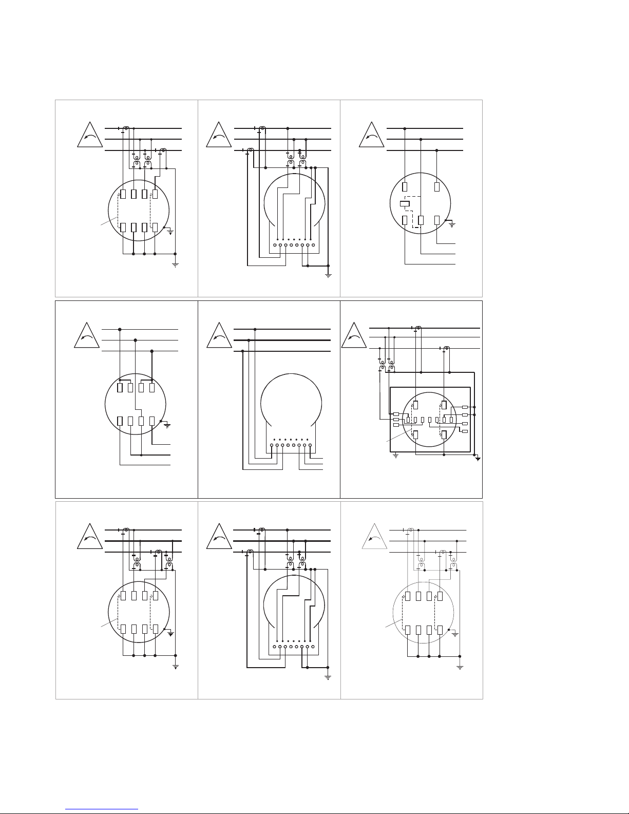
Installation wiring
All available ALPHA meter forms are listed and separated with respect to the type of service being
metered. Use of Form 9S, 10S, and 10A (in 8S and 8A applications), and Form 16S (in Form 15S
application) are also shown. Form 14S and 14A applications are simply 4 wire WYE services and would
be metered by Form 16S and 16A. The more complicated wirings are shown using both PTs and CTs.
The socket ground is shown for safety considerations. The neutral-to-ground connection is shown for
example only. Actual neutral-to-ground connection should be performed within the operating utility's
standard practice.
Single phase meters
ALPHA meter
3
21
1
2
3
Form 5A
3 phase, 3 wire delta, 2 CTs, 0 or 2 PTs
20E01
1
2
3
CIRCUIT
CLOSING
DEVICE
3
21
20E01
Form 5S
3 phase, 3 wire delta, 2 CTs, 0 or 2 PTs
1
2
3
L
O
A
D
2
1
3
3
21
Form 12S
3 phase, 3 wire delta, self–contained
20E01
Form 26S
3 phase, 3 wire delta, 2 CTs, 0 or 2 PTs
20E01
3
21
CIRCUIT
CLOSING
DEVICE
K
Z
Y
1
2
3
Form 13A
3 phase, 3 wire delta, self-contained
20E01
3
21
1
2
3
L
O
A
D
1
2
3
Form 13S
3 phase, 3 wire delta, self-contained
20E01
1
2
3
L
O
A
D
2
1
3
3
21
23A06
Form 45S
3 phase, 3 wire delta, 2 CTs, 0 or 2 PTs
3
21
1
2
3
CIRCUIT
CLOSING
DEVICE
20E01
Form 35S
3 phase, 3 wire delta, 2 CTs, 0 or 2 PTs
3
21
1
2
3
CIRCUIT
CLOSING
DEVICE
3
21
1
2
3
Form 35A
3 phase, 3 wire delta, 2 CTs, 0 or 2 PTs
20E01
IL42-4001S
3 wire delta meters
5
 Loading...