

Elster 6 Series, Q.Sonic Plus Operation And Maintenance Manual
73023467_B_EN
i 2018-06-07
Doc: 10000050188

Page 2 of 68
Operation and Maintenance
UFM Series 6
Q.Sonic-plus
Tel.:
+49 6134 6050
Fax:
+49 6134 605 566
E-Mail:
info@elster-instromet.com
Elster GmbH
Steinern Strasse 19-21
D - 55252 Mainz-Kastel, Germany

Page 3 of 68
Operation and Maintenance
UFM Series 6
Q.Sonic-plus
Contents
1 General Information 6
1.1 About these Instructions 6
1.2 Limitation of Liability 7
2 Text Labelling 8
2.1 Presentation of Safety and Risk Instructions 8
2.1.1 Paragraph Formats 9
2.1.2 Character Formats 10
2.1.3 Abbreviations 11
3 Ultrasonic Flow Meter Series 6 12
3.1 General 12
3.2 Applicable Standards 13
3.3 Configuration 13
3.4 Calibration 14
4 Theory of Operation 15
4.1 Flow Velocity Measurement 15
4.2 Correction after Calibration 16
4.3 Volume Flow at Line Conditions 17
5 System Description 18
5.1 Flow Cell 18
5.2 Signal Processing Unit 19
5.3 Transducers 20
5.4 Flow Cell Pressure Sensor (Optional) 21
5.5 Flow Cell Temperature Sensor 21
5.6 Labels and Nameplates 22
5.6.1 ATEX Certified 23
5.6.2 IECEx Certified 23

Contents
Page 4 of 68
Operation and Maintenance
UFM Series 6
Q.Sonic-plus
5.6.3 FM Certified 24
5.6.4 CSA Certified 25
5.7 Sealing 26
5.7.1 Main Plate 26
5.7.2 SPU 26
6 Installation and Commissioning 29
6.1 Introduction 29
6.2 Flow Cell Installation Requirements 29
6.2.1 Installing a Meter in the Pipeline 29
6.2.2 Testing Installation 30
6.3 Wiring Instructions 31
6.4 SPU Configuration 31
6.5 Cold Commissioning 31
6.6 Hot Commissioning 32
7 Operation 33
7.1 LED at Display 33
7.2 Front Panel and Touch Display 35
7.3 Basic Display 36
7.4 Home Screen 37
7.5 Diagnostics 42
7.6 Info 48
8 Maintenance 50
8.1 Collecting Data 50
8.2 Inspection of Measured Data 50
8.2.1 Sample Rate 50
8.2.2 Performance 51
8.2.3 Velocity of Sound 51
8.2.4 Gas Velocity (Zero Flow Measurement) 51

Contents
UFM Series 6
Q.Sonic-plus
Operation and Maintenance
Page 5 of 68
8.2.5 Presentation of AGC-Levels and AGC-Limits 52
8.2.6 Swirl Angle 52
8.3 Exchanging Components 53
8.3.1 Pressure Sensors Exchange 53
8.3.2 Temperature Sensors Exchange 54
8.3.3 Transducer Exchange 54
8.3.4 SPU Exchange 55
9 Verifying Software Versions 57
9.1 Verifying the Components with their Checksums 57
9.2 Verifying the Software Status of the Parameter Build Up 58
9.3 Display Test 59
9.4 Checking Errors and Warnings 59
9.5 PC Software Package 60
10 User Rights / Login 61
11 Shipping and Storage 62
12 MID Requirements 63
12.1 General 63
12.2 EC Declaration of Conformity 63
12.3 Sealing 64
12.4 Calibration 64
12.5 Installation Requirements 64
13 Index 65
Appendix I – References 67

General Information
1
Page 6 of 68
Operation and Maintenance
UFM Series 6
Q.Sonic-plus
Important!
It is required to read and understand all other documentation of
your meter.
Please see Appendix I – References on page 67 for a
complete list of resources. Additionally, you may look online
at http://www.docuthek.com/.
1 General Information
1.1 About these Instructions
This manual is a complete guide to the operation and maintenance of an
Ultrasonic Flow Meter (UFM) Series 6 Q.Sonic
plus
meter. This manual
together with the UFM Series 6 Safety Instructions and UFM Series 6 Wiring
Instructions provide essential information for safe use in compliance with
and insofar applicable:
European Directives (e.g. ATEX, PED, EMC, MID).
International IECEx standards.
North American FM Approvals standards.
Canadian CSA standards.
This manual explains how to verify which certifications your flow meter
complies with, based on the labelling from the ultrasonic flow meter. The
manual also contains important instructions to prevent accidents and serious
damage before start-up, during operation, and to maintain trouble-free
operation in the safest possible way throughout the entire lifespan of the
device. Before using the product read this manual carefully, familiarise
yourself with the operation of the product, and strictly follow the instructions.
If you have any questions, or need further details on specific matters
concerning this product, please do not hesitate to contact one of our staff
members by email at info@elster-instromet.com (or see more contact
information on page 2).

1
General Information
UFM Series 6
Q.Sonic-plus
Operation and Maintenance
Page 7 of 68
Read through this Operation and Maintenance manual carefully
before beginning any work.
The manufacturer assumes no liability for loss and malfunctions
that result from non-compliance with these instructions.
1.2 Limitation of Liability
This manual is based on the latest information available. It is provided
subject to alterations. We reserve the right to change the construction and/or
configuration of our products at any time without obligation to update
previously shipped equipment.
The warranty provisions stipulated in the manufacturer's Terms of Delivery
are applicable to the product. The manufacturer shall have no obligation in
the event that:
Repair or replacement of equipment or parts is required through
normal wear and tear, or by necessity in whole or part by
catastrophe, or the fault or negligence of the purchaser;
The equipment, or parts, have been maintained or repaired by
someone other than an authorized representative of the
manufacturer, or have been modified in any manner without prior
express written permission of the manufacturer;
Non-original parts are used;
Equipment is used improperly, incorrectly, carelessly or not in line
with its nature and/or purpose;
Use of this product with unauthorized equipment or peripherals,
including, but not necessarily limited to, cables, testing equipment,
computers, voltage, etc.
The manufacturer is not responsible for the incidental or consequential
damages resulting from the breach of any express or implied warranties,
including damage to property, and to the extent permitted by law, damage
for personal injury.
Text Labelling
2
Page 8 of 68
Operation and Maintenance
UFM Series 6
Q.Sonic-plus
DANGER WORD!
Type of danger / consequences in case of non-compliance
Avoiding danger
Safety instruction (optional)
Safety instruction text
We reserve the right to make technical changes within the scope of improving performance characteristics and continuous development of the
device.
Current warranty conditions in the General Terms and Conditions are
available on our website:
http://www.elster-instromet.com/en/general-terms-of-business
2 Text Labelling
This manual employs consistent visual cues and standard text formats to
help you easily locate and interpret information. This information will help
you quickly identify relevant content.
2.1 Presentation of Safety and Risk Instructions
Hazard Warnings
Hazard warnings indicate hazardous situations which may result in material
damage and bodily harm or even death if disregarded. Hazard warnings are
described below:
Safety Instructions
Safety instructions include notes and information which if disregarded may
lead to functions not working correctly or not working at all. Safety
instructions are described below:

2
Text Labelling
UFM Series 6
Q.Sonic-plus
Operation and Maintenance
Page 9 of 68
Heading (optional)
Hint text
Multi-row examples are marked by two continuous blue lines and the
keyword “Example”.
Tips and Recommendations
Tips include notes and information that make it easier for the user. Tips are
described below:
2.1.1 Paragraph Formats
► This triangle prompts you for an action.
This character will show you the immediate result of your action.
Example
Text Labelling
2
Page 10 of 68
Operation and Maintenance
UFM Series 6
Q.Sonic-plus
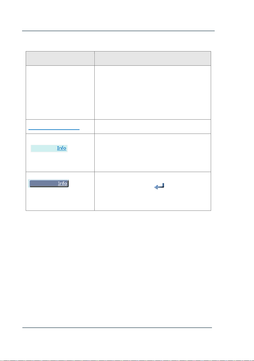
Example
Use
See Chapter 5 System
Description (p.18)
References to additional information are
marked with an arrow. If the arrow refers to
information within the document, these
references are formatted as hyperlinks in blue
font. You can go directly to the corresponding
section by clicking on the blue text.
www.docuthek.com
Links (Hyperlink). Click to open in a browser.
Seen on the meter screen itself; this shows a
hyperlink within the meter software. You must
highlight the hyperlink before it will open the
next screen.
The hyperlink (shown above) has been
highlighted. Press the button on the
touch screen (or PC) to open the new
window. Ex: Open the Info section.
2.1.2 Character Formats
Table 1: Character formats

2
Text Labelling
UFM Series 6
Q.Sonic-plus
Operation and Maintenance
Page 11 of 68
AFB
Application Function Block
ATEX
Atmosphères Explosibles; European Directive
94/9/EC on equipment and protective systems
intended for use in potentially explosive
atmospheres
New Directive (valid 20.04.2016): 2014/34/EU
CSA
Canadian Standards Association
DC
Direct Current
EC
European Community
EMC
ElectroMagnetic Compatibility; European EMC
Directive 2004/108/EC
New directive (valid 20.04.2016): 2014/30/EU
HART
Highway Addressable Remote Transducer
IECEx
International Electrotechnical Commission System
for Certification to Standards Relating to
Equipment for use in Explosive Atmospheres
FM
Factory Mutual Approvals
NMi
Nederlands Meetinstituut
PED
Pressure Equipment Directive; European Directive
97/23/EC concerning pressure equipment
New Directive (valid 19.07.2016): 2014/68/EU
PC
Personal Computer
PCB
Printed Circuit Board
SPU
Signal Processing Unit
UFM
Ultrasonic Flow Meter
2.1.3 Abbreviations
The following abbreviations may appear in this document:

Ultrasonic Flow Meter Series 6
3
Page 12 of 68
Operation and Maintenance
UFM Series 6
Q.Sonic-plus
WARNING!
Improper use of an UFM Series 6 may not only result in
unreliable performance, but may lead to hazardous
situations.
Please refer to the type plates, located on the meter for the
correct operating conditions. Never use the meter outside these
limitations!
3 Ultrasonic Flow Meter Series 6
3.1 General
The UFM Series 6 Q.Sonic
plus
is a sophisticated, multi-path ultrasonic gas
flow meter manufactured by Elster. It has been specifically designed for
custody transfer measuring applications that demand a high degree of
accuracy and reliability. It can be extended with an extra functionality
whereby the flow meter has the possibility to convert the measured line
volume to standardised volume, mass or energy.
The Ultrasonic Flowmeter Series 6 contains 2 type plates:
• Main plate: Provides information on mechanical design conditions as well
as flow related information such as meter factor and range
• SPU type plate: Provides information on applicable hazardous area
approval.
Ensure the meter never operates outside the limits stated on the type plates.
Any discrepancy between the type plates should be reported to Elster or
your local agent immediately. Please refer to Chapter 5.6 Labels and
Nameplates (p.22) for more information.
3
Ultrasonic Flow Meter Series 6
UFM Series 6
Q.Sonic-plus
Operation and Maintenance
Page 13 of 68
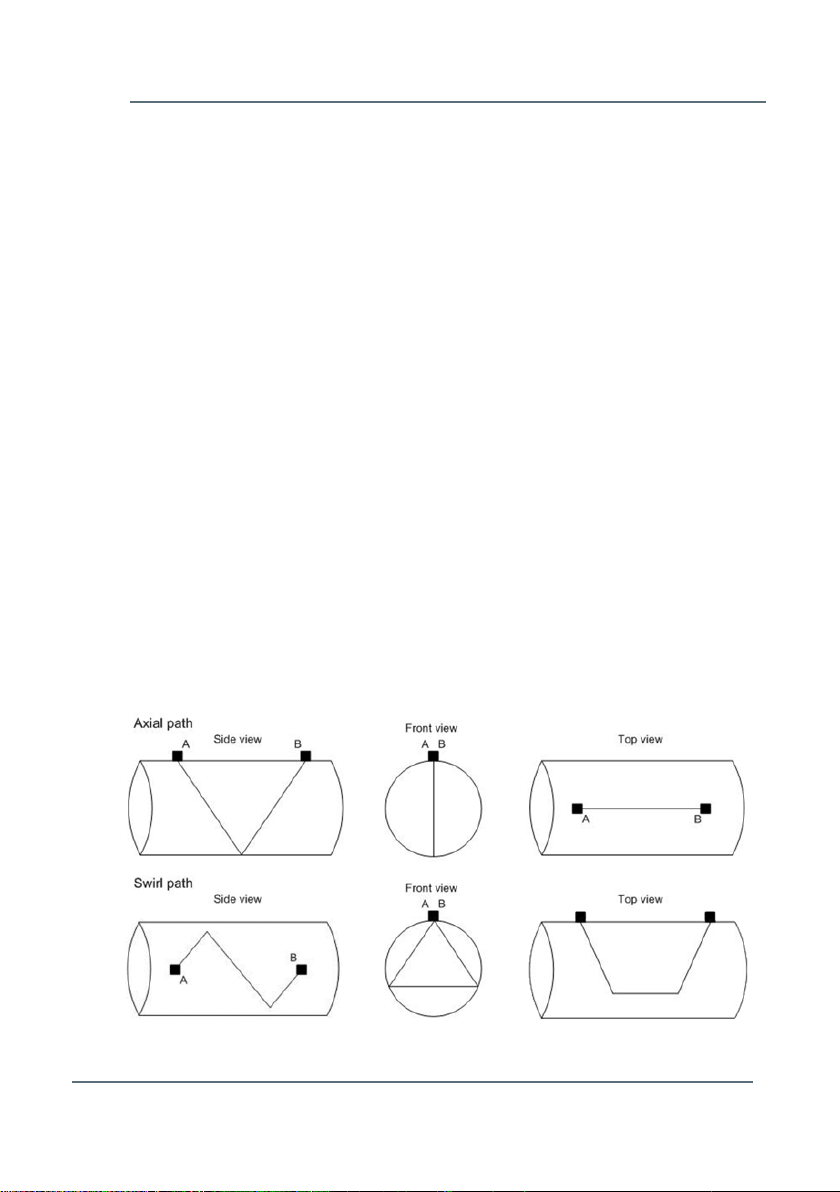
Figure 3-1: Path Types
3.2 Applicable Standards
The Ultrasonic Flow Meter Series 6 is manufactured to be in accordance
with European Directives: ATEX, PED, EMC and optionally MID.
If the meter is ordered for use at a location where European Directives are
NOT mandatory, the meter can alternatively be manufactured in compliance
with IECEx, FM Approval or CSA certificate for use in hazardous areas.
Applicable standards for the optional integrated flow computer functionality
are: AGA8-92 DC, SGERG-88, AGA-NX19 and ISO 6976.
3.3 Configuration
Several pairs of transducers are mounted in pairs on the flow cell of the
UFM. Each pair of transducers represents one individual measuring path.
There are two measuring path types on the Q.Sonic
and Swirl (double bounce). These are shown in Figure 3-1.
The Q.Sonic
plus
path layout consists of 2 axial paths and 4 swirl paths. This
combination results in a completely symmetrical path layout, ensuring the
most optimal accuracy. Figure 3-2 below shows the path layout of the
Q.Sonic
plus
.
plus
: Axial (single bounce)

Ultrasonic Flow Meter Series 6
3
Page 14 of 68
Operation and Maintenance
UFM Series 6
Q.Sonic-plus
Q.Sonic
plus
Path Configuration
Top view:
Front view:
Trd. Path Nr:
Path Type:
1A / 1B
Swirl path (B1-CW*)
2A / 2B
Swirl path (B1-CCW**)
3A / 3B
Axial path (A1)
4A / 4B
Axial path (A2)
5A / 5B
Swirl path (B2-CW*)
6A / 6B
Swirl path (B2-CCW**)
Figure 3-2: Path Layout Q.Sonic
plus
* CW: Path travels clockwise through the pipe
** CCW: Path travels counter-clockwise through the pipe
3.4 Calibration
When using the UFM Series 6 Q.Sonic
most countries demand (by law) a calibration from a certified calibration
institute supervised by an inspector of weights and measures. Examples of
facilities generally used for calibrations are Euroloop in Rotterdam (NL),
TransCanada Calibrations in Canada and PIGSAR GH45 or Open Grid
European Dorsten (D).
plus
in custody transfer applications,
4
Theory of Operation
UFM Series 6
Q.Sonic-plus
Operation and Maintenance
Page 15 of 68
v
B
A
L
D
If the Q.Sonic
plus
meter has to be in accordance with MID, extra restrictions
should be taken into account. Please see Chapter 12.4 Calibration (p.64).
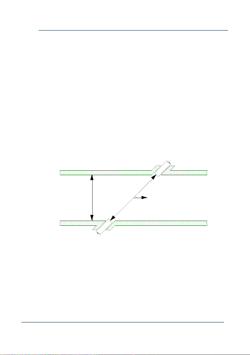
4 Theory of Operation
An ultrasonic flow meter is an inferential measurement device that consists
of ultrasonic transducers that are typically located along a pipe's wall. The
transducers are inserted into the piping using a gas tight mechanism.
Ultrasonic pulses are alternately transmitted by one transducer and received
by the other one.
Figure 4-1 shows a simple geometry of two transducers, ‘A’ and ‘B’, at a
sharp angle “” with respect to the axis of a straight cylindrical pipe with
diameter “D”. Please note: the Q.Sonic
paths, where the acoustic pulses reflect one or more times off the pipe wall.
plus
flow meter employs reflection
4.1 Flow Velocity Measurement
The acoustic pulses are crossing the pipe like a ferryman crossing a river.
Without flow, they propagate with the same speed in both directions. If the
gas in the pipe has a flow velocity different from zero, pulses travelling
downstream with the flow will move faster, while those travelling upstream
against the flow will move slower. Thus, the downstream travel times “tab“ will
Figure 4-1: Ultrasonic Measuring Line

Theory of Operation
4
Page 16 of 68
Operation and Maintenance
UFM Series 6
Q.Sonic-plus
nnn
n
raw
tbatab
L
VoG
n
11
cos2
be shorter, while the upstream ones “tba“ will be longer as compared when
the gas is not moving. The equation below illustrates the computation:
where:
t
the downstream travel time of path n.
abn
t
the upstream travel time of path n.
ban
Ln the straight line length of the acoustic path between
the two transducers.
VoGraw is the average uncorrected (raw) gas velocity.
n the angle between the gas flow and ultrasonic signal.
The raw gas velocity is corrected by a Reynolds flow profile correction. This
correction is depending on the path type. Also the contribution of the gas
velocity of each path to the combined gas velocity is depending on the path
type.
4.2 Correction after Calibration
After flow calibration the meter can be adjusted either through an adjust
factor or through linearization. How the meter is adjusted can be visualized
at the display. Please see Chapter 7.1 LED at Display (p.33).

4
Theory of Operation
UFM Series 6
Q.Sonic-plus
Operation and Maintenance
Page 17 of 68
h
m
D
V
tAVQ
line
lineline
3
2
3600
4
4.3 Volume Flow at Line Conditions
The volume flow at line conditions Q
gas velocity V
multiplied by the internal cross section A of the flow cell:
line
where:
Q
the volume flow at line conditions
Line
V
the adjusted profile-corrected gas velocity
line
D the internal diameter of the meter
A the internal cross-section of the flow cell
t time coefficient to go from seconds to hours.
is the (adjusted) profile-corrected
Line
System Description
5
Page 18 of 68
Operation and Maintenance
UFM Series 6
Q.Sonic-plus
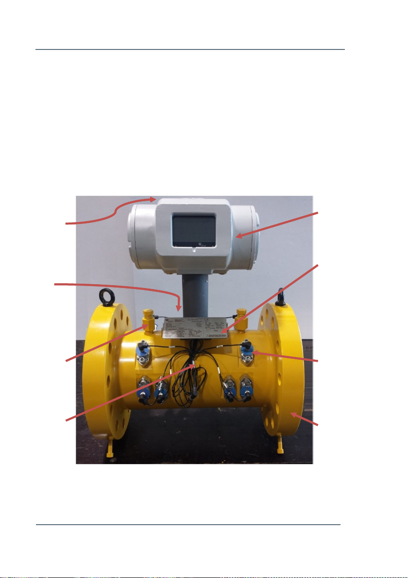
Figure 5-1: Example of an Elster Ultrasonic Gas Flow Meter
SPU label
(rear side)
SPU
Temperature
Sensor
(rear side)
Main Type
Plate
Ultrasonic
Transducer
Flow Cell
Pressure
Connection
Pressure
Sensor
(optional)
5 System Description
5.1 Flow Cell
The flow cell is the part of the UFM Series 6 that is mounted in the piping
system. All components making the UFM Series 6 (SPU, transducers, type
plates, temperature sensor, and optional pressure sensor) are mounted on
the flow cell. Please see Figure 5-1 below.
5
System Description
UFM Series 6
Q.Sonic-plus
Operation and Maintenance
Page 19 of 68
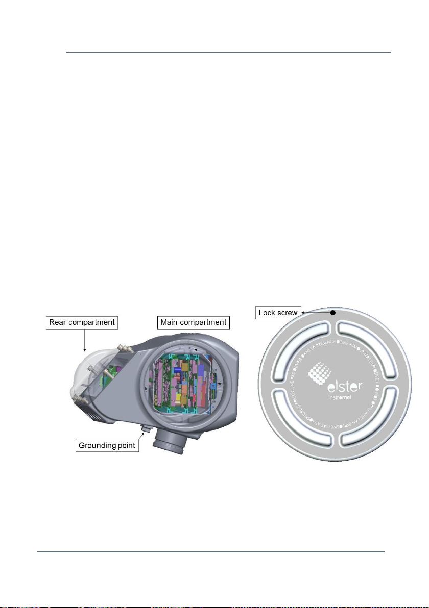
Figure 5-2: SPU Compartments and SPU Cover
5.2 Signal Processing Unit
The SPU is mounted in an explosion proof housing. The box consists of two
separate compartments; a main and a rear compartment (see Figure 5-2).
The main compartment can be opened from the side of the SPU and
contains the main circuit boards. The main compartment also comprises
intrinsically safe connections for the ultrasonic transducers and temperature
and optional pressure sensors. All data processing from excitation of the
transducers to calculating the flow rate is handled by the electronics in this
compartment.
To prevent the box from opening by vibration, the covers on the side need to
be firmly tightened and secured with the lock screw in the cover, as seen in
Figure 5-2. When closing the back compartment, ensure all screws are used.
A grounding point can be seen at the bottom of the SPU. As the meter is
already internally grounded, it is not necessary to use this grounding for
normal operation.
The rear compartment comprises of a field terminal board used for
connecting the Ultrasonic Flow Meter Series 6 to the end user’s applications.
For detailed information about this see Chapter 6.3 Wiring Instructions
(p.31).
System Description
5
Page 20 of 68
Operation and Maintenance
UFM Series 6
Q.Sonic-plus
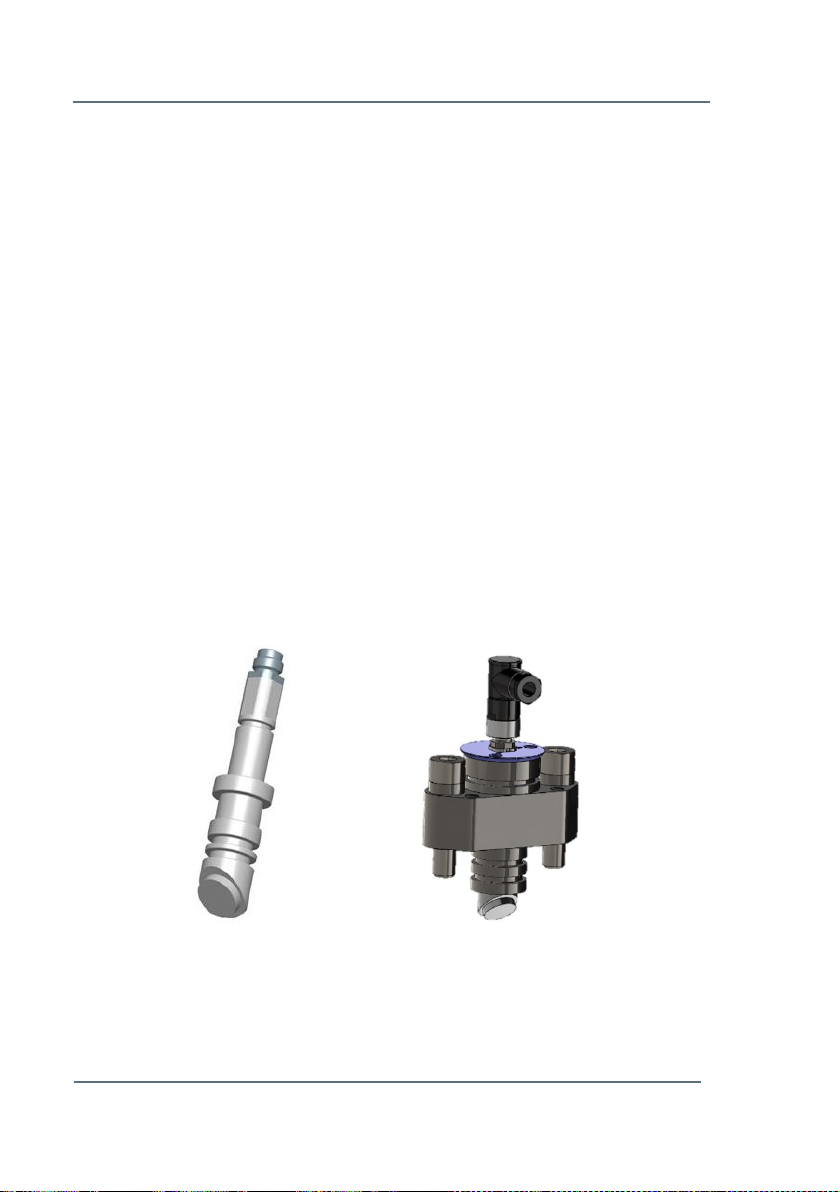
Figure 5-3: NG Transducer
Figure 5-4: NG Transducer
with Mounting Bracket
5.3 Transducers
The ultrasonic signals required for the flow measurement are generated and
received by ultrasonic transducers.
Piezoelectric transducers employ crystals or ceramics that are set into
vibration when an alternating voltage is applied to the piezoelectric element.
The vibrating element generates sound waves in the gas. Since the
piezoelectric effect is reversible, the element will become electrically
polarised and produce voltages related to the mechanical strain, when the
crystal is distorted by the action of incident sound waves. Because the
acoustic impedance of the gas is much smaller compared to the acoustic
impedance of the piezoelectric element, and to maximise the acoustic
efficiency, a matching layer is employed between the gas and the
piezoelectric element.
The transducers used in the Ultrasonic Flow Meter Series 6 are type ‘NG’,
see Figure 5-3. Figure 5-4 visualises the NG transducer with the mounting
bracket.
5
System Description
UFM Series 6
Q.Sonic-plus
Operation and Maintenance
Page 21 of 68
CAUTION!
The pressure sensor is not used for volume conversion.
5.4 Flow Cell Pressure Sensor (Optional)
As an optional feature the UFM can be equipped with a pressure sensor.
This pressure sensor is used for:
Reynolds flow profile correction
Compensation of the flow cell expansion due to gas pressure.
5.5 Flow Cell Temperature Sensor
The UFM is equipped with a temperature sensor. The temperature sensor is
used for:
The Reynolds flow profile correction
Compensation of the flow cell expansion due to flow cell
temperature
 Loading...