

Page 1
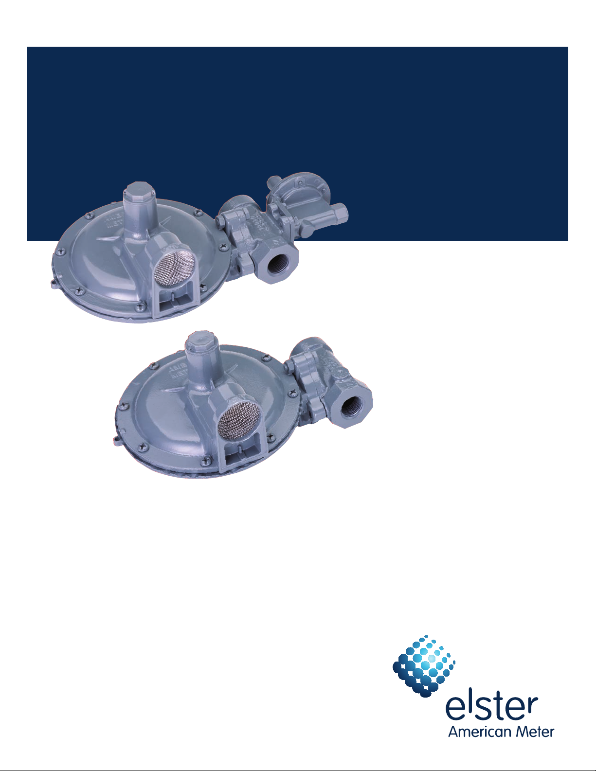
1800C and 1800C-HC Series Service Regulators
Technical Bulletin
Page 2
1800C and 1800C-HC Series Service Regulators 02 Elster American Meter
The 1800C Series pressure regulators are designed to control natural gas,
air, nitrogen, carbon dioxide, propane vapor, and other non-corrosive gases
in residential, light commercial, and small industrial applications.
General Information
Outlet pressures between 3.5" W.C.
and 2 PSIG are available. Operating
temperature range is -20°F to 150°F
(-30°C to 65°C). Maximum flow rate
is 2500 SCFH (70.8 m3/h).
All models conform to ANSI Code
B109.4-1998, and CGA Service-Type Regulator Specification CAN/CGA-6.18-M95.
Features
• Varietyofinterchangeableorifices
and spring ranges
• 90Degree(RightAngle),180Degree
(Straight-Flow),orOffsetValveBody
(See photo below)
• Widerangeofvalvebody
connection sizes
Options
VentElbow
The regulator vent opening should face
downward (6 o'clock) to minimize the
chance of blockage from ice and snow.
If not possible, a 3/4" NPT plastic, 90°
vent elbow (part number 78041P025) and
separate protective screen (part number
70400P017) may be screwed into the vent
to provide the necessary protection.
ElevationCompensation
TheE.C.orificeisrecommendedfor
installations where the inlet pressure
mayvaryoverawiderange.TheE.C.
orifice is available in two sizes: 1/8" x
3/16" and 3/16". The capacities of these
orifices are the same as the standard
orifice of the same size.
Applications
Model Number Description
1813C Basic regulator with full-capacity internal relief with
1813C-HC Basic regulator with full-capacity internal relief with
1843C Basic regulator with full-capacity internal relief and
1843C-HC Basic regulator with full-capacity internal relief and
1853C w/ USSA Basic regulator with full-capacity internal relief and
1853C-HC w/ USSA Basic regulator with full-capacity internal relief and
splashes while providing a large external
vent opening to keep regulators working
properly.
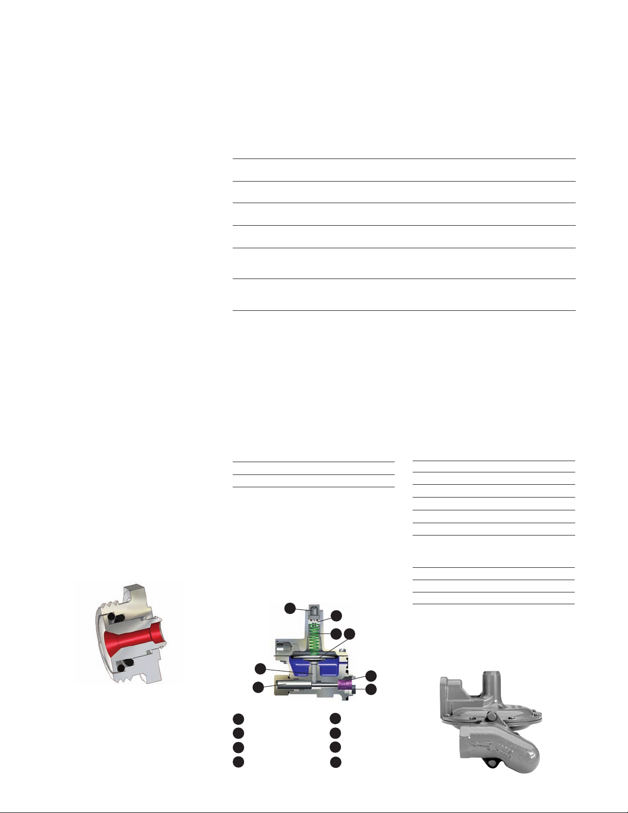
SafetyShutoffDevices
Overpressure Shutoff (OPSO) — Operates
independently. The OPSO will shut off
the gas supply in the event of a serious
downstream pressure build-up. These are
available in two pressure ranges on the
Models 1843C and 1843C-HC.
Spring Range Part Number
14" W.C. to 35" W.C. 71403P005
1 PSIG to 3 1/2 PSIG 71403P004
When the outlet pressure exceeds the
OPSO set point, the pressure under the
OPSO diaphragm (A) compresses the
pressure spring (B) forcing the diaphragm
stem(E)upwardsandreleasingplunger
(D).Thispermitstheshut-offspring(F)
to force the shut-off disc (G) against the
back side of the special double-ended
orifice.
C
H
B A
3/4" or 1" NPT vent.
3/4" or 1" NPT vent.
overpressure shut-off and 3/4" or 1" NPT vent.
overpressure shut-off and 3/4" or 1" NPT vent.
overpressure, underpressure shut-off and 3/4" or 1"
NPT vent.
overpressure, underpressure shut-off and 3/4" or 1"
NPT vent.
Universal Safety Shutoff Assembly
(USSA) — USSA protects the downstream
piping from both over- and under-pressure
conditions by shutting off the gas flow
at the inlet side of the regulator orifice.
Both Over- and under-pressure shut-off
set points are adjustable depending on
spring ranges selected.
USSA Shutoff Spring Ranges
Over Pressure Spring Ranges
Spring Range Part Number
7.5 - 24“ W.C. 70017P123
20 - 32” W.C. 70017P124
24 - 44” W.C. 70017P125
40 - 84” W.C. 70017P126
3 - 5 PSIG 70017P127
4 - 7 PSIG 70017P128
Under Pressure Spring Ranges
Spring Range Part Number
3 - 6“ W.C. 70017P133
6 - 24” W.C. 70017P134
24 - 60” W.C. 70017P135
Pressure Taps
1/8" NPT taps are available on most
valve heads.
FullCapacityReliefValve
Full capacity internal relief valve standard
on all models. (See Performance Graphs
on page 9)
Splashguards
UVstabilized,weather-resistant,resin
device that protects the vent screen from
E
D
A OPSODiaphragmPlate B Pressure Spring
C Cap D Plunger
E DiaphragmStem F Shut-off Spring
G Shut-offDisc H Adjusting Screw
F
G
OffsetValveBody
Page 3
1800C and 1800C-HC Series Service Regulators 03 Elster American Meter
2
4
9
11
5 13
14
3
1
15
12
7
6
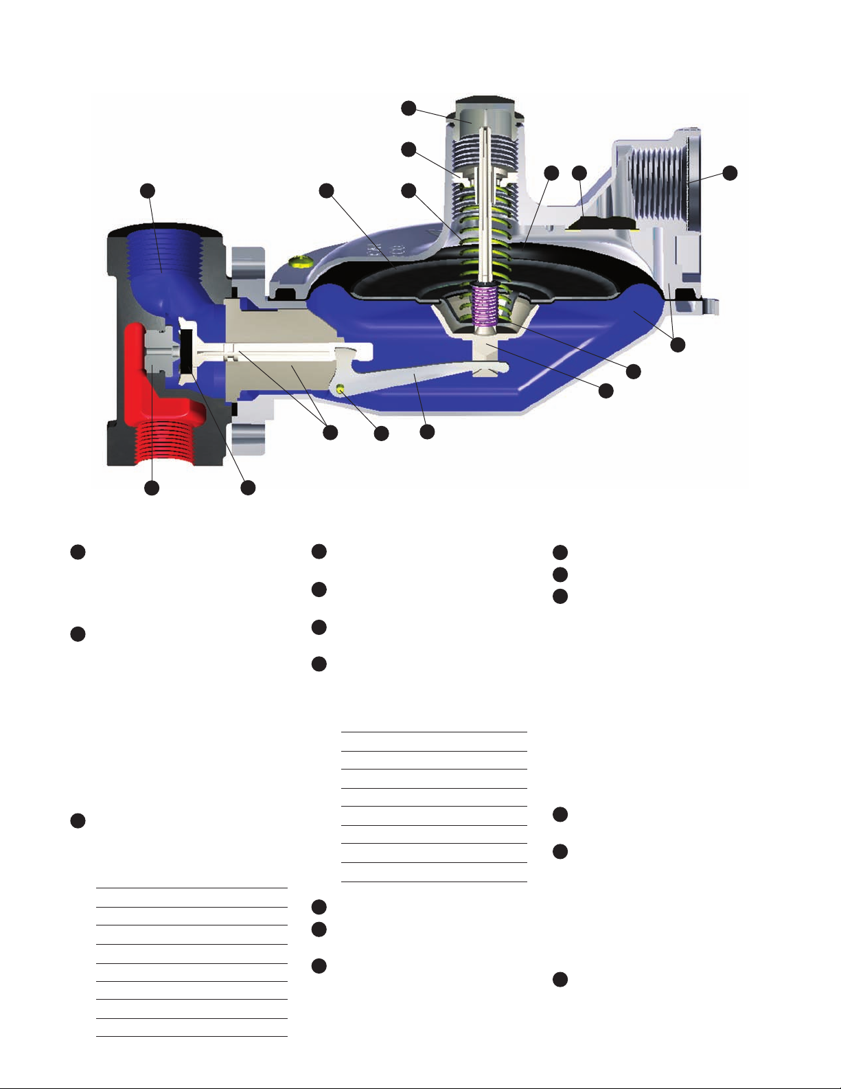
Material Specifications
1 Diaphragm Case - Precision die-cast
aluminum with an exclusive seven step advanced conversion coating,
single-coat polyester primer and
high solids polyurethane top coat.
2 Valve Body - Cast grey iron,
undercoated, single coat polyester
primer and high solids polyurethane
top coat. NPT threads meet ANSI/
ASME B1.20.1. BSP-TR threads meet
BS EN 10226.
Available sizes: 3/4” x 3/4”, 3/4” x 1”,
3/4” x 1-1/4”, 1” x 1”, 1” x 1-1/4” and
1-1/4” x 1-1/4” NPT or BSP-TR
Offset valve body: 3/4” x 3/4”,
3/4” x 1” and 1” x 1” NPT or BSP-TR
3 Pressure Spring - Steel, zinc plated
and yellow chromate. Color coded
for identification.
Outlet
Pressure
3.5" to 6" W.C. Blue 70017P043
3.5" to 7.5" W.C. Tan 70017P089
5.5" to 8.5" W.C. Yellow 70017P044
6" to 12" W.C. Brown 70017P137
6" to 15" W.C. Purple 70017P042
12" to 28" W.C. White 70017P060
24" to 48" W.C. Red 70017P082
42" W.C. to 2 PSIG Red - Red 70017P049
Color
Code
Part
Number
10
4 Diaphragm Plate - Steel,
16
8
Electrogalvanized.
5 Diaphragm - Buna N; Nylon
fabric reinforced.
6 Seat Disc - Buna N; 60, 70 (std.)
or 80 durometer rating.
7 Orifice Valve - High strength,
corrosion resistant aluminum.
Orifice
Size
9/16" 72494P026 72751P019
1/2" 72494P025 72751P016
3/8" 72494P023 72751P014
5/16" 72494P022 72751P013
1/4" 72494P021 72751P012
3/16" 72494P020 72751P011
1/8" x 3/16" 72494P030 72751P020
1/8" 72494P019 N/A
8 Lever - Stamped aluminum.
9 Seal Plug - Polyester thermoplastic
Standard
Part
Number
Part Number
with OPSO
UV stabilized.
10 Plunger Valve/Plunger Guide -
Minlon.
11 Pressure Adjustment Screw - Minlon.
12 Relief Valve Stem - Minlon.
13 Vent Screen - Stainless Steel -
All models are designed with a
removable weather and bug-proof
stainless steel screen to resist freeze ups and to exclude foreign matter.
The vent is threaded ¾” or 1”
NPT (BSP-TR threads available).
Inside installation requires a vent
line of sufficient diameter to carry
gas vented by the regulator to a
safe outside location away from
any opening(s) in the structure.
Comply with applicable Federal,
State and local codes.
14 Vent Valve - Stainless Steel with
Electrogalvanized steel retainer.
15 Relief Valve Spring - Steel, zinc
plated and yellow chromate.
Color coded for identification.
Non-adjustable, standard set point
of 8" w.c. above outlet set pressure
of 7" w.c. Standard set point of
1.3 PSIG above outlet set pressure
of 2 PSIG.
16 Lever Pin - Carbon steel, zinc plated
and yellow chromate.
Page 4

1800C and 1800C-HC Series Service Regulators 04 Elster American Meter
1800C Series Regulator Capacity Performance
3/4" Outlet
Set Point 7.0" W.C. (17.4 mbar)
at 50 SCFH
SCFH (m3/h) 0.60 specific gravity gas at
60°F and 14.7 PSIA (20°C and 1.01 bar).
Pressure spring 70017P044. Outlet
pressure variance not to exceed +2" -1" W.C.
from set point, horizontal position.
1800C Series Regulator Capacity SCFH (m3/h)
Inlet
PSIG
1/8" x 3/16"
(bar)
1
(0.07)
2
(0.14)
3
(0.21)
5
(0.34)
10
(0.70)
15
(1.00)
20
(1.40)
30
(2.10)
40
(2.80)
60
(4.10)
100
(6.90)
125
(8.60)
For optimum performance, maximum inlet pressure should not exceed maximum capacity rating for any given
orifice size.
Orifice
—
—
—
275
(7.8)
375
(10.6)
450
(12.7)
500
(14.2)
700
(19.8)
800
(22.7)
1100
(31.2)
1700
(48.1)
2100
(59.5)
3/16"
Orifice
175
(5.0)
300
(8.5)
375
(10.6)
500
(14.2)
750
(21.2)
950
(26.9)
1100
(31.2)
1400
(39.6)
1700
(48.1)
2300
(65.1)
2500
(70.8)
— — — — — —
1/4"
Orifice
250
(7.1)
425
(12.0)
500
(14.2)
700
(19.8)
1100
(31.2)
1400
(39.6)
1700
(48.1)
2000
(56.6)
2400
(68.0)
2500
(70.8)
2500
(70.8)
5/16"
Orifice
325
(9.2)
475
(13.5)
600
(17.0)
800
(22.7)
1200
(34.0)
1500
(42.5)
1700
(48.1)
2200
(62.3)
2500
(70.8)
2500
(70.8)
— — — —
3/8"
Orifice
350
(9.9)
550
(15.6)
700
(19.8)
950
(26.9)
1400
(39.6)
1600
(45.3)
1900
(53.8)
2400
(68.0)
2500
(70.8)
— — —
1/2"
Orifice
400
(11.3)
650
(18.4)
800
(22.7)
1000
(28.3)
1500
(42.5)
1900
(53.8)
2200
(62.3)
2500
(70.8)
— —
9/16"
Orifice
400
(11.3)
650
(18.4)
800
(22.7)
1200
(34.0)
1700
(48.1)
2000
(56.6)
2300
(65.1)
—
1" Outlet
Set Point 7.0" W.C. (17.4 mbar)
at 50 SCFH
SCFH (m3/h) 0.60 specific gravity gas at
60°F and 14.7 PSIA (20°C and 1.01 bar).
Pressure spring 70017P044. Outlet
pressure variance not to exceed +2" -1" W.C.
from set point, horizontal position.
1800C Series Regulator Capacity SCFH (m3/h)
Inlet
PSIG
1/8" x 3/16"
(bar)
1
(0.07)
2
(0.14)
3
(0.21)
5
(0.34)
10
(0.70)
15
(1.00)
20
(1.40)
30
(2.10)
40
(2.80)
60
(4.10)
100
(6.90)
125
(8.60)
For optimum performance, maximum inlet pressure should not exceed maximum capacity rating for any given
orifice size.
Orifice
—
—
—
250
(7.1)
350
(9.9)
425
(12.0)
500
(14.2)
600
(17.0)
750
(21.2)
1000
(28.3)
1600
(45.3)
2000
(56.6)
3/16"
Orifice
175
(5.0)
250
(7.1)
300
(8.5)
450
(12.7)
700
(19.8)
900
(25.5)
1100
(31.2)
1400
(39.6)
1700
(48.1)
2400
(68.0)
2500
(70.8)
— — — — — —
1/4"
Orifice
250
(7.1)
350
(9.9)
450
(12.7)
650
(18.4)
1000
(28.3)
1400
(39.6)
1700
(48.1)
2300
(65.1)
2500
(70.8)
2500
(70.8)
— — — — —
5/16"
Orifice
300
(8.5)
450
(12.7)
550
(15.6)
750
(21.2)
1400
(39.6)
1900
(53.8)
2300
(65.1)
2500
(70.8)
2500
(70.8)
— — — —
3/8"
Orifice
375
(10.6)
500
(14.2)
700
(19.8)
950
(26.9)
1600
(45.3)
2100
(59.5)
2500
(70.8)
2500
(70.8)
— — —
1/2"
Orifice
475
(13.5)
600
(17.0)
850
(24.1)
1200
(34.0)
1900
(53.8)
2500
(70.8)
2500
(70.8)
— —
9/16"
Orifice
500
(14.2)
650
(18.4)
950
(26.9)
1300
(36.8)
2000
(56.6)
2500
(70.8)
—
Page 5

1800C and 1800C-HC Series Service Regulators 05 Elster American Meter
1800C Series Regulator Capacity Performance
1-1/4" Outlet
Set Point 7.0" W.C. (17.4 mbar)
at 50 SCFH
SCFH (m3/h) 0.60 specific gravity gas at
60°F and 14.7 PSIA (20°C and 1.01 bar).
Pressure spring 70017P044. Outlet
pressure variance not to exceed +2" -1" W.C.
from set point, horizontal position.
1800C Series Regulator Capacity SCFH (m3/h)
Inlet
PSIG
1/8" x 3/16"
(bar)
1
(0.07)
2
(0.14)
3
(0.21)
5
(0.34)
10
(0.70)
15
(1.00)
20
(1.40)
30
(2.10)
40
(2.80)
60
(4.10)
100
(6.90)
For optimum performance, maximum inlet pressure should not exceed maximum capacity rating for any given
orifice size.
Orifice
— 200
— 325
— 425
275
(7.8)
375
(10.6)
450
(12.7)
550
(15.6)
700
(19.8)
800
(22.7)
1100
(31.2)
1400
(39.6)
3/16"
Orifice
(5.7)
(9.2)
(12.0)
550
(15.6)
850
(24.1)
1000
(28.3)
1200
(34.0)
1600
(45.3)
— — — — — —
— — — — — —
— — — — — —
1/4"
Orifice
325
(9.2)
500
(14.2)
650
(18.4)
1000
(28.3)
1500
(42.5)
1800
(51.0)
2100
(59.5)
— — — — —
5/16"
Orifice
350
(9.9)
600
(17.0)
950
(26.9)
1600
(45.3)
2400
(68.0)
2500
(70.8)
— — — —
3/8"
Orifice
375
(10.6)
700
(19.8)
1200
(34.0)
2100
(59.5)
2500
(70.8)
— — —
1/2"
Orifice
475
(13.5)
950
(26.9)
1700
(48.1)
2500
(70.8)
2500
(70.8)
9/16"
Orifice
500
(14.2)
1400
(39.6)
1900
(53.8)
2500
(70.8)
2500
(70.8)
3/4" Outlet
Set Point 2 PSIG (0.14 bar)
at 50 SCFH
SCFH (m3/h) 0.60 specific gravity gas at
60°F and 14.7 PSIA (20°C and 1.01 bar).
Pressure spring 70017P049. Outlet
pressure variance not to exceed +/- 10%
from set point, horizontal position.
1800C Series Regulator Capacity SCFH (m3/h)
Inlet
PSIG
1/8" x 3/16"
(bar)
3
(0.21)
5
(0.34)
10
(0.70)
15
(1.00)
20
(1.40)
30
(2.10)
40
(2.80)
60
(4.10)
100
(6.90)
125
(8.60)
For optimum performance, maximum inlet pressure should not exceed maximum capacity rating for any given
orifice size.
Orifice
150
(4.2)
250
(7.1)
375
(10.6)
450
(12.7)
550
(15.6)
700
(19.8)
850
(24.1)
1100
(31.2)
1700
(48.1)
2100
(59.5)
3/16"
Orifice
175
(5.0)
325
(9.2)
550
(15.6)
750
(21.2)
900
(25.5)
1200
(34.0)
1500
(42.5)
2100
(59.5)
2500
(70.8)
— — — — — —
1/4"
Orifice
300
(8.5)
450
(12.7)
700
(19.8)
900
(25.5)
1200
(34.0)
1500
(42.5)
2000
(56.6)
2500
(70.8)
— — — — —
5/16"
Orifice
325
(9.2)
525
(14.9)
825
(23.4)
1100
(31.2)
1300
(36.8)
1800
(51.0)
2200
(62.3)
— — — —
3/8"
Orifice
375
(10.6)
575
(16.3)
1000
(28.3)
1300
(36.8)
1600
(45.3)
2100
(59.5)
— — —
1/2"
Orifice
400
(11.3)
700
(19.8)
1200
(34.0)
1500
(42.5)
1900
(53.8)
— —
9/16"
Orifice
500
(14.2)
750
(21.2)
1300
(36.8)
1800
(51.0)
—
Page 6

1800C and 1800C-HC Series Service Regulators 06 Elster American Meter
1800C Series Regulator Capacity Performance
1" Outlet
Set Point 2 PSIG (0.14 bar)
at 50 SCFH
SCFH (m3/h) 0.60 specific gravity gas at
60°F and 14.7 PSIA (20°C and 1.01 bar).
Pressure spring 70017P049. Outlet
pressure variance not to exceed +/- 10%
from set point, horizontal position.
1800C Series Regulator Capacity SCFH (m3/h)
Inlet
PSIG
1/8" x 3/16"
(bar)
3
(0.21)
5
(0.34)
10
(0.70)
15
(1.00)
20
(1.40)
30
(2.10)
40
(2.80)
60
(4.10)
100
(6.90)
125
(8.60)
For optimum performance, maximum inlet pressure should not exceed maximum capacity rating for any given
orifice size.
Orifice
150
(4.2)
225
(6.4)
350
(9.9)
425
(12.0)
500
(14.2)
650
(18.4)
800
(22.7)
1100
(31.2)
1700
(48.1)
2100
(59.5)
3/16"
Orifice
225
(6.4)
350
(9.9)
600
(17.0)
800
(22.7)
1000
(28.3)
1300
(36.8)
1700
(48.1)
2500
(70.8)
2500
(70.8)
— — — — — —
1/4"
Orifice
250
(7.1)
450
(12.7)
750
(21.2)
1000
(28.3)
1200
(34.0)
1700
(48.1)
2200
(62.3)
2500
(70.8)
— — — — —
5/16"
Orifice
350
(9.9)
500
(14.2)
850
(24.1)
1100
(31.2)
1400
(39.6)
2000
(56.6)
2500
(70.8)
— — — —
3/8"
Orifice
425
(12.0)
650
(18.4)
1000
(28.3)
1400
(39.6)
1800
(51.0)
2500
(70.8)
— — —
1/2"
Orifice
550
(15.6)
750
(21.2)
1300
(36.8)
1700
(48.1)
2100
(59.5)
— —
9/16"
Orifice
550
(15.6)
900
(25.5)
1500
(42.5)
2000
(56.6)
—
1-1/4" Outlet
Set Point 2 PSIG (0.14 bar)
at 50 SCFH
SCFH (m3/h) 0.60 specific gravity gas at
60°F and 14.7 PSIA (20°C and 1.01 bar).
Pressure spring 70017P049. Outlet
pressure variance not to exceed +/- 10%
from set point, horizontal position.
1800C Series Regulator Capacity SCFH (m3/h)
Inlet
PSIG
1/8" x 3/16"
(bar)
3
(0.21)
5
(0.34)
10
(0.70)
15
(1.00)
20
(1.40)
30
(2.10)
40
(2.80)
60
(4.10)
100
(6.90)
125
(8.60)
For optimum performance, maximum inlet pressure should not exceed maximum capacity rating for any given
orifice size.
Orifice
150
(4.2)
225
(6.4)
350
(9.9)
425
(12.0)
500
(14.2)
650
(18.4)
800
(22.7)
1100
(31.2)
1700
(48.1)
2100
(59.5)
3/16"
Orifice
225
(6.4)
350
(9.9)
600
(17.0)
850
(24.1)
1000
(28.3)
1500
(42.5)
1900
(53.8)
2500
(70.8)
2500
(70.8)
— — — — — —
1/4"
Orifice
350
(9.9)
500
(14.2)
850
(24.1)
1200
(34.0)
1700
(48.1)
2500
(70.8)
2500
(70.8)
2500
(70.8)
— — — — —
5/16"
Orifice
375
(10.6)
600
(17.0)
1100
(31.2)
1600
(45.3)
2200
(62.3)
2500
(70.8)
2500
(70.8)
— — — —
3/8"
Orifice
425
(12.0)
700
(19.8)
1200
(34.0)
1900
(53.8)
2500
(70.8)
2500
(70.8)
— — —
1/2"
Orifice
550
(15.6)
900
(25.5)
1700
(48.1)
2500
(70.8)
2500
(70.8)
— —
9/16"
Orifice
550
(15.6)
1100
(31.2)
2200
(62.3)
2500
(70.8)
—
Page 7

1800C and 1800C-HC Series Service Regulators 07 Elster American Meter
1800C-HC Series Regulators
Ideal for light commercial and industrial use, the 1-1/4"
1800C-HC Series regulator is designed to increase output
capacity during medium to high inlet pressure operations.
General Information
The 1800C-HC Series regulator’s
lightweight design features high-capacity
capabilities for 1-1/4" NPT connections
and flow capacities up to 4900 SCFH
depending on inlet pressure and orifice
selection. It complements the 1800C
Series family of regulators.
AC-630 Meter with 1813C-HC Regulator
1800C-HC Series Regulator
Capacity Performance
1-1/4" Outlet
Set Point 7.0" W.C. (17.4 mbar)
at 50 SCFH
SCFH (m3/h) 0.60 specific gravity gas at
60°F and 14.7 PSIA (20°C and 1.01 bar).
Pressure spring 70017P044. Outlet
pressure variance not to exceed +2" -1" W.C.
from set point, horizontal position.
1800C Series Regulator Capacity SCFH (m3/h)
Inlet PSIG
(bar)
(0.07)
(0.14)
(0.21)
(0.34)
(0.70)
(1.00)
(1.40)
(2.10)
(2.80)
(4.10)
(6.90)
(8.60)
For optimum performance, maximum inlet pressure should not exceed maximum capacity rating for any given
orifice size.
10
15
20
30
40
60
100
125
1/8" x 3/16"
Orifice
1
2
3
5
—
—
—
275
(7.8)
350
(9.9)
425
(12.0)
475
(13.5)
600
(17.0)
750
(21.2)
1100
(31.2)
1600
(45.3)
2000
(56.6)
3/16"
Orifice
175
(5.0)
275
(7.8)
350
(9.9)
450
(12.7)
600
(17.0)
950
(26.9)
1100
(31.2)
1500
(42.5)
1800
(51.0)
2500
(70.8)
3800
(107.6)
— — — — — —
1/4"
Orifice
200
(5.7)
350
(9.9)
450
(12.7)
700
(19.8)
1100
(31.2)
1300
(36.8)
1900
(53.8)
2500
(70.8)
3200
(90.6)
4400
(124.6)
— — — — —
5/16"
Orifice
250
(7.1)
450
(12.7)
600
(17.0)
850
(24.1)
1500
(42.5)
2300
(65.1)
2900
(82.1)
4000
(113.3)
4900
(138.8)
4900
(138.8)
3/8"
Orifice
350
(9.9)
525
(14.9)
750
(21.2)
1000
(28.3)
1600
(45.3)
2600
(73.6)
3400
(96.3)
4600
(130.3)
4900
(138.8)
— — —
1/2"
Orifice
475
(13.5)
675
(19.1)
800
(22.7)
1500
(42.5)
2500
(70.8)
3300
(93.5)
4200
(118.9)
4900
(138.8)
— —
9/16"
Orifice
525
(14.9)
800
(22.7)
1100
(31.2)
1600
(45.3)
2700
(76.5)
3300
(93.5)
3900
(110.4)
—
Page 8

1800C and 1800C-HC Series Service Regulators 08 Elster American Meter
1800C and 1800C-HC Series Service
Regulators - Other Technical Data
Full-Open Regulator
Relief Capacity
For sizing downstream relief valves,
use the following formulas to determine
the regulator full-open capacity:
Critical flow rates Sub-critical flows
P
Q = 0.5 C x Q = C x
Critical flow occurs when the absolute
outlet pressure is less than about 1/2
of the absolute inlet pressure.
Q Maximum capacity of regulator
C Orifice constant (see table below)
P1 Inlet absolute pressure (PSIA)
P2 Outlet absolute pressure (PSIA)
h Differentialpressure
G Specific gravity of gas
1
√G
√P2h
√G
Orifice Constants
Orifice C
1/8" 25
1/8" x 3/16" 25
3/16" 57
1/4" 98
5/16" 149
3/8" 208
1/2" 353
9/16" 421
Maximum Recommended
Maximum Recommended
Inlet Pressure
Inlet Pressure
Orifice Size Inlet Pressure (PSIG)
9/16" 20
1/2" 50
3/8" 70
5/16" 125
1/4" 125
3/16" 125
1/8" x 3/16" 125
1/8" 125
This is the maximum inlet the regulator should operate
at to insure complete lockup at no-flow conditions.
Other Gas Capacities
To determine the capacity of these regulators for gases other than natural gas, multiply
the values within the capacity tables by a Specific Gravity Conversion Factor (Fg). The
table below lists this factor for some of the more common gases.
Gas Type Specific Gravity Conversion Factor (Fg)
Air 1.00 0.77
Butane 2.01 0.55
CarbonDioxide 1.52 0.63
Nitrogen 0.97 0.79
Propane 1.53 0.63
To calculate the Conversion Factor for other gases:
(Fg) =
Example:Ifusingpropaneandonlyhavingtablesbasedonnaturalgas,
the Specific Gravity Conversion Factor is :
(Fg) =
(Fg) =
(Fg) = 0.626
Specific gravity of gas on which the capacity table is based
√
Specific gravity of natural gas (0.6)
Specific gravity of propane (1.53)
√
0.60
1.53
√
Specific gravity of gas being used
Regulator Pressure Rating
125 PSIG (8.6 bar) = Maximum recommended inlet pressure for normal service.
Maximum recommended pressure may vary with orifice size.
175 PSIG (12 bar) = Maximum inlet pressure for abnormal or emergency service,
without causing damage to regulator case.
2 PSIG (138 mbar) = Maximum outlet pressure for normal service.
10 PSIG (689 mbar) = Maximum outlet pressure which can be contained by pressure
carrying components (no flange leakage to atmosphere except for normal relief action).
If regulator is subjected to these conditions, it should be removed from service.
50 PSIG (3.5 bar) = Maximum outlet pressure for abnormal service without damage to
internal components. If regulator is subjected to these conditions, it should be removed
from service.
Page 9

1800C and 1800C-HC Series Service Regulators 09 Elster American Meter
90
(224)
80
(199)
70
(174)
60
(149)
50
(124)
40
(100)
30
(75)
20
(50)
10
(25)
0
0 10 20 30 40 50 60 70 80 90 100 110 120 130
(.7) (1.4) (2.1) (2.8) (3.4) (4.1) (4.8) (5.5) (6.2) (6.9) (7.6) (8.3) (9.0)
9/16” 3/8” 1/4” 1/8“ x 3/16”
1/2” 5/16” 3/16”
Outlet Pressure - Inches W.C. (mbar)
Inlet Pressure - PSIG (bar)
9
(.62)
8
(.55)
7
(.48)
6
(.41)
5
(.34)
4
(.26)
3
(.21)
2
(.14)
1
(.07)
0
0 10 20 30 40 50 60 70 80 90 100 110 120 130
(.7) (1.4) (2.1) (2.8) (3.4) (4.1) (4.8) (5.5) (6.2) (6.9) (7.6) (8.3) (9.0)
9/16” 3/8” 1/4” 1/8“ x 3/16”
1/2” 5/16” 3/16”
Outlet Pressure - PSIG (bar)
Inlet Pressure - PSIG (bar)
9
(.62)
8
(.55)
7
(.48)
6
(.41)
5
(.34)
4
(.26)
3
(.21)
2
(.14)
1
(.07)
0
0 10 20 30 40 50 60 70 80 90 100 110 120 130
(.7) (1.4) (2.1) (2.8) (3.4) (4.1) (4.8) (5.5) (6.2) (6.9) (7.6) (8.3) (9.0)
9/16” 3/8” 1/4” 1/8“ x 3/16”
1/2” 5/16” 3/16”
Outlet Pressure - PSIG (bar)
Inlet Pressure - PSIG (bar)
90
(224)
80
(199)
70
(174)
60
(149)
50
(124)
40
(100)
30
(75)
20
(50)
10
(25)
0
0 10 20 30 40 50 60 70 80 90 100 110 120 130
(.7) (1.4) (2.1) (2.8) (3.4) (4.1) (4.8) (5.5) (6.2) (6.9) (7.6) (8.3) (9.0)
9/16” 3/8” 1/4” 1/8“ x 3/16”
1/2” 5/16” 3/16”
Outlet Pressure - Inches W.C. (mbar)
Inlet Pressure - PSIG (bar)
1800C and 1800C-HC Series Service Regulators
RegulatorReliefValvePerformance
There are several methods of measuring the relief performance of a regulator.
The worst case scenario will occur when the lever is disconnected. The data
presented in the tables below represent this condition.
Outlet Pressure Relative to Inlet Pressure
3/4"ScreenedVent–NoVentPipeSetPressure7"W.C.
1"ScreenedVent–NoVentPipeSetPressure7"W.C.
3/4"ScreenedVent–NoVentPipeSetPressure2PSIG
2 PSIG
1 PSIG
2 PSIG
1 PSIG
1"ScreenedVent–NoVentPipeSetPressure2PSIG
Page 10

1800C and 1800C-HC Series Service Regulators 10 Elster American Meter
C
F
D
E
A
B
C
F
D
E
A
B
C
F
D
E
A
B
C
F
D
E
A
B
1800C and 1800C-HC Series
Service Regulator Dimensions
C
F
D
E
A
B
Model 1813C - 90°
Inlet Outlet A B C D E F
3/4" 3/4" 1-9/16"
39.7mm
3/4" 1" 1-9/16"
39.7mm
1" 1" 1-9/16"
39.7mm
8-7/8"
225.4mm
8-7/8"
225.4mm
8-7/8"
225.4mm
7-1/4"
184.2mm
7-1/4"
184.2mm
7-1/4"
184.2mm
4-1/8"
104.8mm2"50.8mm
4-1/8"
104.8mm2"50.8mm
4-1/8"
104.8mm2"50.8mm
3-5/8"
92.1mm
3-5/8"
92.1mm
3-5/8"
92.1mm
Model 1813C and 1813C-HC - 180°
C
F
D
E
A
B
Inlet Outlet A B C D E F
3/4" 3/4" 1"
25.4mm
3/4" 1" 1"
25.4mm
1" 1" 1"
25.4mm
1" 1-1/4" 1-1/8"
28.6mm
1-1/4" 1-1/4" 1-1/8"
28.6mm
3/4" 1-1/4" 1-1/8"
28.6mm
8-7/8"
225.4mm
8-7/8"
225.4mm
8-7/8"
225.4mm
8-7/8"
225.4mm
8-7/8"
225.4mm
8-7/8"
225.4mm
7-1/4"
184.2mm
7-1/4"
184.2mm
7-1/4"
184.2mm
7-1/4"
184.2mm
7-1/4"
184.2mm
7-1/4"
184.2mm
4-1/8"
104.8mm2"50.8mm
4-1/8"
104.8mm2"50.8mm
4-1/8"
104.8mm2"50.8mm
4-1/8"
104.8mm2"50.8mm
4-1/8"
104.8mm2"50.8mm
4-1/8"
104.8mm2"50.8mm
92.1mm
92.1mm
92.1mm
92.1mm
92.1mm
92.1mm
3-5/8"
3-5/8"
3-5/8"
3-5/8"
3-5/8"
3-5/8"
C
F
D
E
A
B
Model 1813C - Offset
Inlet Outlet A B C D E F
3/4" 3/4" 1"
25.4mm
3/4" 1" 1"
25.4mm
1" 1" 1"
25.4mm
8-7/8"
225.4mm
8-7/8"
225.4mm
8-7/8"
225.4mm
7-1/4"
184.2mm
7-1/4"
184.2mm
7-1/4"
184.2mm
4-1/8"
104.8mm2"50.8mm
4-1/8"
104.8mm2"50.8mm
4-1/8"
104.8mm2"50.8mm
3-5/8"
92.1mm
3-5/8"
92.1mm
3-5/8"
92.1mm
Model 1843C and 1843C-HC
C
D
E
A
F
B
Inlet Outlet A B C D E F
3/4" 3/4" 4-1/2"
114.3mm
3/4" 1" 4-1/2"
114.3mm
1" 1" 4-1/2"
114.3mm
1" 1-1/4" 4-1/2"
114.3mm
1-1/4" 1-1/4" 4-1/2"
114.3mm
8-15/16"
227.0mm
8-15/16"
227.0mm
8-15/16"
227.0mm
8-15/16"
227.0mm
8-15/16"
227.0mm
7-1/4"
184.2mm
7-1/4"
184.2mm
7-1/4"
184.2mm
7-1/4"
184.2mm
7-1/4"
184.2mm
4-1/8"
104.8mm2"50.8mm
4-1/8"
104.8mm2"50.8mm
4-1/8"
104.8mm2"50.8mm
4-1/8"
104.8mm2"50.8mm
4-1/8"
104.8mm2"50.8mm
92.1mm
92.1mm
92.1mm
92.1mm
92.1mm
3-5/8"
3-5/8"
3-5/8"
3-5/8"
3-5/8"
Page 11

1800C and 1800C-HC Series Service Regulators 11 Elster American Meter
Standard
Vent Position
Standard
Vent Position
2
4
31
2
4
31
Standard
Vent Position
Valve Head Position "D"
Standard
Vent Position
Valve Head Position "C"
Valve Head Position "B"
Valve Head Position "A"
4
2
1
3
2
4
31
Standard
Vent Position
Valve Head Position "D"
1
3
2
4
Standard
Vent Position
4
2
1
3
Valve Head Position "B"
Standard
Vent Position
2
4
3
1
Valve Head Position "A"
Standard
Vent Position
Valve Head Position "C"
2
4
3
1
Standard
Vent Position
VENT
Valve Head Position "D"
2
4
3
1
Regulator Assembly Positions
180° Models
AC-250 Meter with 1813C Regulator
90° Models
Offset Models
ExampleofRegulator
Assembly Position
In the photo above the 1813C Regulator
shown has an 180 degree valve head in
Position "C" (Flow upward) with the vent in
position 2 (Looking down). This would be
assembly position C2.
Ordering Information
1 Model number
2 Size of inlet and outlet
3 Inlet pressure, PSIG (bar)
4 Outlet pressure, inches w.c.
(mbar) or PSIG (bar)
5 Flow, scfh (m3/h)
6 Kind and specific gravity of gas
7 Orifice size
8 Regulator assembly position
number
9 Possible variation in inlet pressure
forE.C.Orificemodels
Maximum ___ PSIG (bar)
Minimum ___ PSIG (bar)
Shipping Weight
17.5 lbs/carton of four regulators
Page 12

AboutElsterGroup
A world leader in advanced metering
infrastructure, integrated metering, and
utilization solutions to the gas, electricity
andwaterindustries,Elster’ssystems
and solutions reflect over 170 years of
knowledge and experience in measuring
precious resources and energy.
Elsterprovidessolutionsandadvanced
technologies to help utilities more easily,
efficiently and reliably obtain and use
advanced metering intelligence to
improve customer service, enhance
operational efficiency, and increase
revenues.Elster'sAMIsolutionsenable
utilities to cost-effectively generate, deliver,
manage, and conserve the life-essential
resources of gas, electricity, and water.
Elsterhasover7,500staffand
operations in 38 countries in North
andSouthAmerica,Europe,andAsia.
ElsterAmericanMeter
2221 Industrial Road
NebraskaCity,NE68410
USA
T +1 402 873 8200
F +1 402 873 7616
www.elster-americanmeter.com
ElsterCanadianMeter
T +1 519 650 1900
F +1 519 650 1917
www.elster-canadianmeter.com
©2008ElsterAmericanMeter.Allrightsreserved
Information contained herein is subject to change
without notice. Product specifications may change.
ContactyourElsterAmericanMeterrepresentative
for the most current product information. Printed in
the United States.
EAM-TB8515.11-EN-P-June2008
SupersedesEAM-TB8515.10-EN-P
 Loading...