

Page 1
SB-8510.4
Measurement Engineers Since 1836
www.americanmeter.com
1800B2 & 1800B2-HC
Service Regulators
Maximum Inlet Pressure 125 PSIG
Dutch Council
for Accreditation
AMC Quality System
QMI is Accredited by:
ISO 9001 Certified
Certificate #006697
ANSI RAB
A
C
C
R
E
D
I
T
E
D
R
E
G
I
S
T
R
A
R
Page 2
against downstream overpressure. Models 1853B2 and
1893B2 also include an underpressure shut-off (UPSO)
that provides protection in the event of an upstream failure.
Valve body configuration permits the 1800B2 Series regulators to be supplied in four positions as specified on page
7. All Series 1800B2 regulators are available with either
right angle (90 degree) or straight flow (180-degree)
valve bodies. Vents can also be supplied in four
different positions.
All models are designed with an extra large, removable
weather and bug-proof stainless steel screened vent to
resist freeze-ups and to exclude foreign matter.The vent is
threaded 3/4 or 1 inch NPT and is also available with BSPTR threads making it suitable for indoor installations.
Options
Vent Elbow- The regulator vent opening should face downward (6 o'clock)to minimize the chance of blockage from
ice and snow. If not, a 3/4" NPT plastic, 90˚ vent elbow
(Part number 78041P025) and separate protective screen
(Part number 70400P017) may be screwed into the vent to
provide the necessary protection.
Elevation Compensation- E.C. orifices are also available,
which provide constant outlet pressure even when inlet
pressure fluctuates greatly. The elevation compensation
orifice is a device which reduces changes in regulator
outlet pressure due to change in inlet pressure.
The E.C.orifice is recommended for installations where the
inlet pressure may vary over a wide range.The E.C. orifice
is available in two sizes: 1/8" x 3/16" (Part number
73698G006) and 3/16" (Part number 73698G005). Its
capacity is the same as a standard orifice of the same size.
Consult your American Meter Sales Representative for
specific applications.
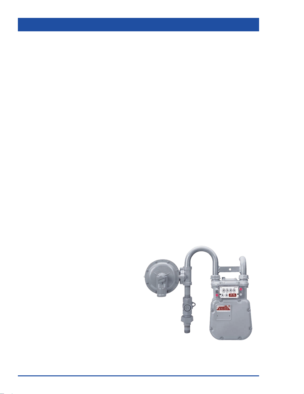
① AC-250 Meter ➁ 1813B2 Regulator
2
1800B2 Service Regulators
➁
➀
General Information
The American Meter Series 1800B2 pressure regulators are
designed for natural gas applications and features a compact, lightweight design for fast, easy installation.
Interchangeable orifices and springs provide a wide range
of outlet pressures and flow rates.Outlet pressures between
3.5" W.C. and 2 PSIG are available. Operating temperature
range is -20˚ F to 150˚ F (-30˚C to 65˚C). Maximum flow rate
is 2500 SCFH (70.8 m3/h).
The diaphragm case may be easily removed for routine
inspection without disturbing the line connections. All models conform to ANSI Code B109.4-1998, and CGA Servicetype Regulator Specification CAN/CGA-6.18-M95.
Exclusive, 7 - Step Corrosion
Protection
The protective finish on the Series 1800B2 regulators
resists corrosive effects of weather and harsh environments better than any other in the industry. Each precision
die cast aluminum regulator is treated-inside and out-with a
special conversion coating that's part of an exclusive, 7step finishing process.This coating greatly inhibits oxidation
of the metal's surface that can eventually compromise the
integrity of the metal. It also prevents finish paint from
cracking and blistering.
A single coat polyester primer and the high solid
polyurethane top coat provides a long-lasting protection to
all exterior regulator surfaces.The American Meter conversion coating process meets all environmental protection
regulations.
High Tensile Strength Valve Bodies
Each Series of 1800B2 regulator is equipped with a high
tensile strength cast iron valve body that rotates in 90degree increments and features extr a hea vy w all thic kness.
This provides maximum strength to withstand installation
stresses without damage and prevents thread galling
experienced with aluminum.
Series 1800B2 regulator valve bodies are treated with a 5step metal finishing process. The treated metal is painted
with a single coat polyester paint.
Available valve body sizes are: 3/4" x 3/4", 3/4" x 1",
3/4" x 1-1/4", 1" x 1", 1" x 1-1/4" and 1-1/4" x 1-1/4" NPT or
BSP-TR. Also available is a offset valve body in 3/4" x
3/4", 3/4" x 1" and 1" x 1" NPT or BSP-TR.
Application
Models 1813B2, 1833B2, 1843B2 and 1853B2 features a
full capacity internal relief valve with large passages to
assure the fast release of gas (See performance graphs on
page 6). For added protection, a relief valve stop is provided to assure operation under the most severe conditions.
The standard relief spring setting is 8.0" W.C. above the
normal 7" W.C. outlet pressure.
Models 1843B2, 1853B2, 1883B2 & 1893B2 are equipped
with overpressure shut-off (OPSO) that provides protection
Page 3
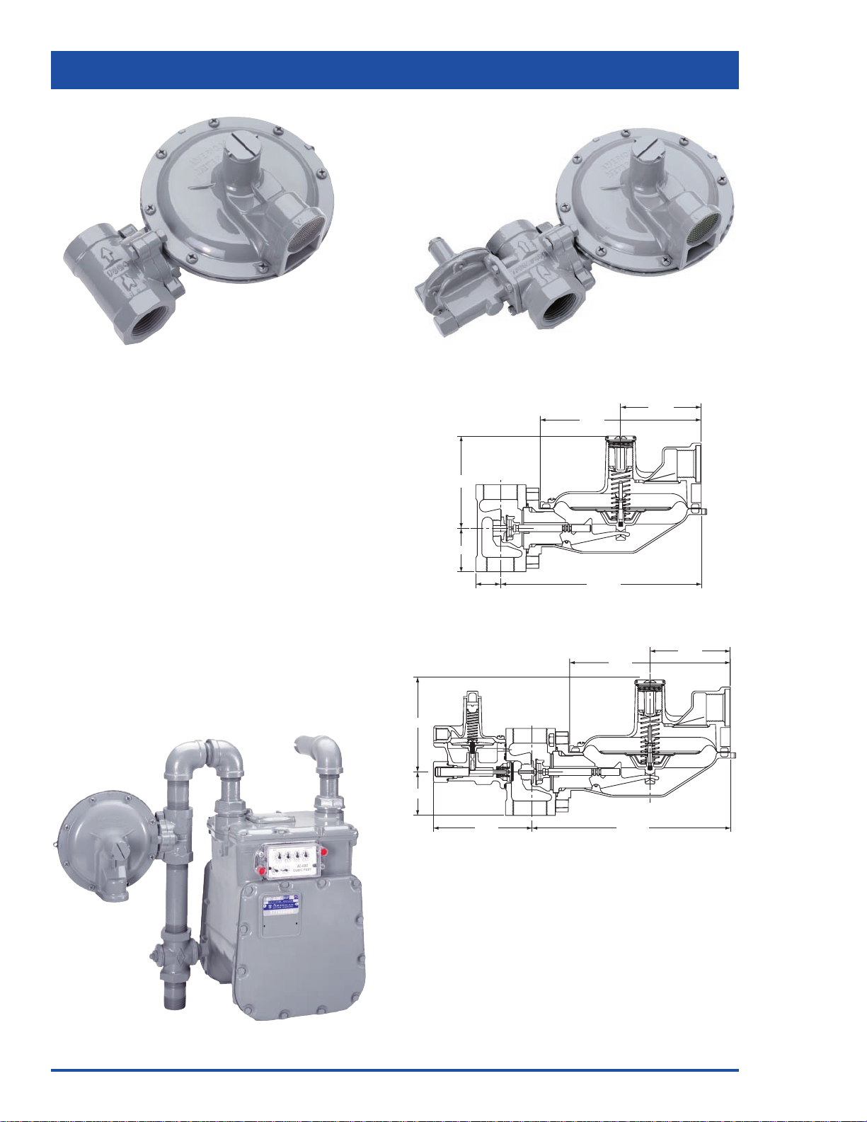
1813B2-HC-180˚ Dimensions
1843B2-HC Dimensions
3
1800B2-HC Service Regulators
General Information
Ideal for light commercial and industrial use, the 1-1/4"
1800B2-HC Series regulator is designed to increase output
capacity and lessen compounding during medium- to highinlet pressure operations. Compounding usually occurs
when a larger valve body introduces undesirable flow
characteristics, thereby creating an inefficient, boosting
effect in the outlet port of the body.
The 1800B2-HC regulator’s lightweight design features
high-capacity capabilities for 1-1/4" NPT connections and
flow capacities up to 4600 SCFH depending on inlet
pressure and orifice selection. It complements the 1800B2
Series family of regulators.
A lightweight regulator designed to increase capacity output and minimize the outlet boosting effect that is typical
from a larger valve body.
All models conform to ANSI Code B109.4-1998 and CGA
Service-type Regulator Specification CAN/CGA-6.18-M95.
① AC-630 Meter ➁ 1813B2-HC Regulator
1-3/16"
2"
1-15/16"
4-1/8"
7-1/4"
3-5/8"
3-5/8"
7-1/4"
4-1/8"
2"
4-1/2"
8-15/16"
1813B2-HC 1843B2-HC
➀
➁
Page 4

4
Inlet Outlet A B C D E F
3/4" 3/4" 4-1/2" 8-15/16" 7-1/4" 5-1/8" 2" 3-5/8"
3/4" 1" 4-1/2" 8-15/16" 7-1/4" 5-1/8" 2" 3-5/8"
1" 1" 4-1/2" 8-15/16" 7-1/4" 5-1/8" 2" 3-5/8"
1" 1-1/4" 4-1/2" 8-15/16" 7-1/4" 5-1/8" 2" 3-5/8"
1-1/4" 1-1/4" 4-1/2" 8-15/16" 7-1/4" 5-1/8" 2" 3-5/8"
AE
Inlet Outlet 90˚* 180˚* Offset B C D E Offset F
3/4" 3/4" 1-9/16" 1" 1” 8-7/8" 7-1/4" 5-1/8" 2" 2” 3-5/8"
3/4" 1" 1-9/16" 1" 1” 8-7/8" 7-1/4" 5-1/8" 2" 2” 3-5/8"
1" 1" 1-9/16" 1" 1" 8-7/8" 7-1/4" 5-1/8" 2" 2" 3-5/8"
1" 1-1/4" — 1-1/8" — 8-7/8" 7-1/4" 5-1/8" 2" — 3-5/8"
1-1/4" 1-1/4" — 1-1/8" — 8-7/8" 7-1/4" 5-1/8" 2" — 3-5/8"
3/4" 1-1/4" — 1-1/8" — 8-7/8" 7-1/4" 5-1/8" 2" — 3-5/8"
*1833B2 Only
1800B2 Service Regulators
Dimensions Model 1843B2 & 1883B2
Model 1803B2-180˚ Model 1813B2-180˚
Model 1813B2-Offset Model 1843B2
Model 1883B2 Not Shown
Model 1833B2-90˚ Model 1853B2
Model 1823B2 Not Shown Model 1893B2 Not Shown
Dimensions Model 1803B2 & 1813B2
Inlet Outlet A B C D E F
3/4" 3/4" 4-1/2" 8-15/16" 7-1/4" 4-1/8" 2" 3-5/8"
3/4" 1" 4-1/2" 8-15/16" 7-1/4" 4-1/8" 2" 3-5/8"
1" 1" 4-1/2" 8-15/16" 7-1/4" 4-1/8" 2" 3-5/8"
1" 1-1/4" 4-1/2" 8-15/16" 7-1/4" 4-1/8" 2" 3-5/8"
1-1/4" 1-1/4" 4-1/2" 8-15/16" 7-1/4" 4-1/8" 2" 3-5/8"
Dimensions Model 1853B2 & 1893B2
Dimensions Model 1823B2 & 1833B2
A
B
C
F
D
E
F
C
B
D
E
A
C
D
A
B
F
E
C
F
B
A
E
D
F
A
B
D
C
E
F
C
D
B
A
E
AE
Inlet Outlet 90˚*180˚* Offset B C D E Offset F
3/4" 3/4" 1-9/16" 1" 1” 8-7/8" 7-1/4" 4-1/8" 2" 2” 3-5/8"
3/4" 1" 1-9/16" 1" 1” 8-7/8" 7-1/4" 4-1/8" 2" 2” 3-5/8"
1" 1" 1-9/16" 1" 1" 8-7/8" 7-1/4" 4-1/8" 2" 2" 3-5/8"
1" 1-1/4" — 1-1/8" — 8-7/8" 7-1/4" 4-1/8" 2" — 3-5/8"
1-1/4" 1-1/4" — 1-1/8" — 8-7/8" 7-1/4" 4-1/8" 2" — 3-5/8"
3/4" 1-1/4" — 1-1/8" — 8-7/8" 7-1/4" 4-1/8" 2" — 3-5/8"
*1813B2 Only
Page 5

5
Overpressure Shut-off Regulators
Overpressure Shut-off (OPSO)
Regulators
Models 1843B2, 1843B2-HC, 1853B2, 1883B2, 1883B2-HC
and 1893B2 regulators are compact units designed to regulate line pressure and to provide protection against any
downstream overpressure.
Rugged, Compact OPSO - Operates independently. The
OPSO will shut-off the gas supply in the event of a serious
downstream pressure build-up.
Adjustable Overpressure Shut-off - Pressure is adjustable
via the overpressure shut-off adjustment screw to settings
from 14" to 35" W.C.and 1 to 3-1/2 PSIG depending on spring
selected.
Extra Safety - Models 1843B2, 1843B2-HC and 1853B2
provide added protection by incorporating a full capacity relief
valve.This inter nal valve is the same as in the 1813B2 and
1813B2-HC and operates in the same manner to combine
safety features.
How The OPSO Operates
When the outlet pressure exceeds the OPSO set point, the
pressure under the OPSO diaphragm (A) compresses the
pressure spring (B) forcing the diaphragm stem (E) upwards
and releasing plunger (D).This permits the shut-off spring (F)
to force the shut-off disc (G) against the back side of the
special double ended orifice.
Shut-off Assembly Adjustable Trip Point Range
72978G070 14" to 35" W.C.
72978G071 1 to 3-1/2 PSIG
Note: When selecting the shut-off spring range, a
differential of 14" W.C. above the normal operating pressure
and the shut-off pressure is recommended for normal line
pressure variations. The OPSO setting is preset at the
factory to the desired trip point.
To reset the OPSO simply unscrew cap (C), pull back the
plunger (D) until the diaphragm stem (E) repositions.
B
D
C
A
G
F
E
Overpressure Shut-off
Tripped Position
1800B2 & 1800B2-HC Service Regulators
For sizing downstream relief valves, use
the following formulas to determine the
regulator full open capacity:
For critical flow rates For sub-critical flows
Key:
Q = Maximum capacity of regulator
C = Or ifice constant, see table
P
1
= Inlet absolute pressure (PSIA)
P
2
= Outlet absolute pressure (PSIA)
h = Differential pressure (P1 - P2)
G = Specific gravity of gas
Full Open Regulator Relief Capacity
Q = 0.5 C x
P
1
G
Q=C
P
2
h
G
Orifice C
1/8" 25
1/8" x 3/16" 25
3/16" 57
1/4" 98
5/16" 149
3/8" 208
1/2" 353
9/16" 421
Page 6

6
Inlet Orifice Size
(PSIG) 1/8 x 3/16 3/16 1/4 5/16 3/8 1/2 9/16
1 150 175 250 300 350 350
2 150 225 275 375 400 475 475
3 200 300 375 425 500 550 600
5 250 400 500 600 700 800 1000
10 350 600 850 1000 1200 1300 1400
15 425 900 1100 1500 1500 1500 1600
20 500 1100 1400 1600 1800 1800 1900
30 650 1400 1800 2100 2100 2100
40 800 1800 2200 2400 2500
60 1100 2200 2500 2500
100 1700 2400 2500
125 2000
Inlet Orifice Size
(PSIG) 1/8 x 3/16 3/16 1/4 5/16 3/8 1/2 9/16
1 150 200 275 350 400 400
2 175 250 350 475 500 650 900
3 225 325 475 550 700 1000 1500
5 275 475 750 1000 1200 2000 2500
10 375 800 1500 2200 2500 2500 2500
15 450 1000 1800 2500 2500 2500 2500
20 500 1200 2100 2500 2500
30 650 1600 2500
40 800 1900
60 1100
100 1700
1800B2 Service Regulators
Inlet Orifice Size
(PSIG) 1/8 x 3/16 3/16 1/4 5/16 3/8 1/2 9/16
3 200 225 275 300 375 450
5 200 300 375 475 475 600 700
10 325 450 600 750 800 1100 1200
15 425 600 800 1000 1000 1400 1500
20 500 750 1000 1200 1300 1600 1800
30 600 950 1300 1600 1700 2300
40 750 1200 1600 1900 2100 2500
60 1100 1600 2100 2300 2500
100 1600 2200 2500
125 2000
Inlet Orifice Size
(PSIG) 1/8 x 3/16 3/16 1/4 5/16 3/8 1/2 9/16
1 150 200 250 300 350 350
2 175 250 350 375 400 475 475
3 200 325 400 425 500 550 600
5 275 425 550 600 700 1000 1000
10 350 650 900 1000 1400 1500 1800
15 425 900 1200 1500 1800 2100 2400
20 500 1100 1600 1800 2300 2500 2500
30 650 1400 2000 2500 2500 2500
40 800 1800 2500 2500 2500 2500
60 1100 2400 2500 2500 2500
100 1700 2500 2500
125 2000
1800B2 Regulator Capacity Performance
Capacity 1" Outlet 1800B2 Regulator
Set Point 7.0" W.C. @ 50 SCFH
SCFH 0.60 specific gravity gas @ 60˚ F & 14.7 PSIA. Pressure spring
70017P044. Outlet pressure variance not to exceed +2" -1" W.C. from
set point, horizontal position.
Capacity 3/4" Outlet 1800B2 Regulator
Set Point 7.0" W.C. @ 50 SCFH
SCFH 0.60 specific gravity gas @ 60˚ F & 14.7 PSIA. Pressure spring
70017P044. Outlet pressure variance not to exceed +2" -1" W.C. from
set point, horizontal position.
Capacity 1-1/4" Outlet 1800B2 Regulator
Set Point 7.0" W.C. @ 50 SCFH
SCFH 0.60 specific gravity gas @ 60˚ F & 14.7 PSIA. Pressure spring
70017P044. Outlet pressure variance not to exceed +2" -1" W.C. from
set point, horizontal position.
Capacity 3/4" Outlet 1800B2 Regulator
Set Point 2 PSIG @ 50 SCFH
SCFH 0.60 specific gravity gas @ 60˚ F & 14.7 PSIA. Pressure spring
70017P049. Outlet pressure variance not to exceed +/- 10% from set
point, horizontal position.
For optimum performance, maximum inlet
pressure should not exceed maximum capacity
rating for any given orifice size.
For optimum performance, maximum inlet
pressure should not exceed maximum capacity
rating for any given orifice size.
For optimum performance, maximum inlet
pressure should not exceed maximum capacity
rating for any given orifice size.
For optimum performance, maximum inlet
pressure should not exceed maximum capacity
rating for any given orifice size.
Inlet Orifice Size
(PSIG) 1/8 x 3/16 3/16 1/4 5/16 3/8 1/2 9/16
3 200 225 275 300 375 450
5 200 300 375 475 500 600 750
10 350 500 600 750 950 1200 1400
15 425 650 850 1100 1300 1800 2100
20 500 850 1100 1400 1700 2400 2500
30 650 1100 1600 2300 2500 2500
40 800 1500 2200 2500 2500 2500
60 1100 2400 2500 2500 2500
100 1700 2500 2500
125 2100
Inlet Orifice Size
(PSIG) 1/8 x 3/16 3/16 1/4 5/16 3/8 1/2 9/16
3 200 225 275 300 375 450
5 200 300 375 475 475 600 700
10 350 475 600 750 850 1200 1300
15 425 650 850 1000 1100 1500 1700
20 500 800 1100 1300 1400 2000 2300
30 650 1000 1500 1800 2000 2500
40 800 1300 1900 2400 2500 2500
60 1100 2100 2500 2500 2500
100 1600 2500 2500
125 2000
Capacity 1" Outlet 1800B2 Regulator
Set Point 2 PSIG @ 50 SCFH
SCFH 0.60 specific gravity gas @ 60˚ F & 14.7 PSIA. Pressure spring
70017P049. Outlet pressure variance not to exceed +/- 10% from set
point, horizontal position.
Capacity 1-1/4" Outlet 1800B2 Regulator
Set Point 2 PSIG @ 50 SCFH
SCFH 0.60 specific gravity gas @ 60˚ F & 14.7 PSIA. Pressure spring
70017P049. Outlet pressure variance not to exceed +/- 10% from set
point, horizontal position.
For optimum performance, maximum inlet
pressure should not exceed maximum capacity
rating for any given orifice size.
For optimum performance, maximum inlet
pressure should not exceed maximum capacity
rating for any given orifice size.
Page 7

7
Inlet Orifice Size
(PSIG) 1/8 x 3/16 3/16 1/4 5/16 3/8 1/2 9/16
1 150 225 225 200 325 300
2 150 200 275 300 350 375 450
3 200 250 350 350 425 600 600
5 250 350 425 500 600 750 850
10 350 500 650 800 800 1500 1700
15 425 600 900 950 1500 2200 2300
20 500 750 1000 2100 2200 2700 2900
30 650 1200 1700 3600 3000 3900
40 800 1650 2600 4300 4100
60 1100 2500 4500 4600 3900
100 1700 3900
125 1900
1800B2-HC Service Regulators
Capacity 1-1/4" Outlet 1800B2-HC Regulator
Set Point 7.0" W.C. @ 50 SCFH
SCFH 0.60 specific gravity gas @ 60˚ F & 14.7 PSIA. Pressure spring
70017P044. Outlet pressure variance not to exceed +2" -1" W.C. from
set point, horizontal position.
For optimum performance, maximum inlet
pressure should not exceed maximum capacity
rating for any given orifice size.
1800B2-HC Regulator Capacity Performance
1800B2 & 1800B2-HC Service Regulators
Pressure Springs Orifice Sizes
Outlet Pressure Color Code Part Number
3.5" to 6" W.C. Blue 70017P043
3.5" to 7.5" W.C. Tan 70017P089
5.5" to 8.5" W.C. Yellow 70017P044
6" to 15" W.C. Purple 70017P042
12" to 28" W.C. White 70017P060
24" to 48" W.C. Red 70017P082
42" W .C. to Red-Red 70017P049
2 PSIG
Orifice Size Inlet Pressure
(PSIG)
9/16" 20
1/2" 40
3/8" 100
5/16" 110
1/4" 125
3/16" 125
1/8" x 3/16" 125
1/8" 125
Orifice Size Part Number
Standard w/ OPSO
9/16" 72494P026 72751P019
1/2" 72494P025 72751P016
3/8" 72494P023 72751P014
5/16" 72494P022 72751P013
UPSO 71422G004 71422G004
1/4" 72494P021 72751P012
3/16" 72494P020 72751P011
1/8" x 3/16" 72494P030 72751P020
1/8" 72494P019 N/A
See page 5 for maximum inlet recommendations and capacity
performance for each orifice size.
Maximum Recommended Inlet Pressure
Page 8

8
1800B2 & 1800B2-HC Service Regulators
0 10 20 30 40 50 60 70 80 90 100 110 120 130
90
80
70
60
50
40
30
20
10
0
Outlet Pressure - Inches W.C.
Inlet Pressure - PSIG
Outlet Pressure Relative To Inlet Pressure
3/4" Screened Vent - No Vent Pipe
Set Pressure 7" W.C.
0 10 20 30 40 50 60 70 80 90 100 110 120 130
9
8
7
6
5
4
3
2
1
0
Outlet Pressure - PSIG
Inlet Pressure - PSIG
Outlet Pressure Relative To Inlet Pressure
3/4" Screened Vent - No Vent Pipe
Set Pressure 2 PSIG
0 10 20 30 40 50 60 70 80 90 100 110 120 130
90
80
70
60
50
40
30
20
10
0
Outlet Pressure - Inches W.C.
Inlet Pressure - PSIG
Outlet Pressure Relative To Inlet Pressure
1" Screened Vent - No Vent Pipe
Set Pressure 7" W.C.
0 10 20 30 40 50 60 70 80 90 100 110 120 130
9
8
7
6
5
4
3
2
1
0
Outlet Pressure - PSIG
Inlet Pressure - PSIG
Outlet Pressure Relative To Inlet Pressure
1" Screened Vent - No Vent Pipe
Set Pressure 2 PSIG
Regulator Relief Valve Performance
There are several methods of measuring the relief performance of a regulator.The worst case scenario will occur when the lever
is disconnected.The data presented in the tables below represent this condition.
5/16"
3/8"
9/16" 1/2"
1/4"
3/16"
1/8" x 3/16"
5/16"
3/8"
9/16"
1/4"
3/16"
1/8" x 3/16"
1/2"
5/16"
3/8"
9/16"
1/4"
3/16"
1/8" x 3/16"
1/2"
5/16"
3/8"
9/16"
1/4"
3/16"
1/8" x 3/16"
1/2"
Page 9

Model Description
Number
1803B2 Basic regulator, non-relieving with 3/4" or 1" NPT vent.
&1803B2-HC
1813B2 Basic regulator with full capacity internal relief with 3/4" or 1" NPT vent.
& 1813B2-HC
1823B2 Basic regulator, non-relieving with under-pressure shut-off and 3/4" or 1" NPT vent.
*
1833B2 Basic regulator with full capacity internal relief and underpressure shut-off and
* 3/4" or 1" NPT vent.
1843B2 Basic regulator with full capacity internal relief and overpressure shut-off and
& 1843B2-HC 3/4" or 1" NPT vent.
1853B2 Basic regulator with full capacity internal relief and overpressure, underpressure shut-off
* and 3/4" or 1" NPT vent.
1883B2 Basic regulator, non-relieving with over-pressure shut-off and 3/4" or 1" NPT vent.
& 1883B2-HC
1893B2 Basic regulator, non-relieving with over-pressure, underpressure shut-off and
* 3/4" or 1" NPT vent.
1853B2 w/ Jeavons Basic regulator with full capacity internal relief and overpressure, underpressure
& 1853B2-HC w/ Jeavons shut-off and 3/4" or 1" NPT vent.
**
1893B2 w/ Jeavons Basic regulator, non-relieving with overpressure, underpressure shut-off and
& 1893B2-HC w/ Jeavons 3/4" or 1" NPT vent.
**
9
1800B2 & 1800B2-HC Service Regulators
Regulator Assembly Positions
For 180˚ Models For Offset Models For 90˚ Models
Regulator Descriptions
* For UPSO operation, see Brochure TDB-8620.
** For Jeavons (USSA) operation, see Brochure SB-8556.
1
4
2
3
STANDARD
VENT POSITION
VALVE HEAD POSITION "D"
VENT
73985
VENT
3
2
1
4
STANDARD
VENT POSITION
VENT
3
2
4
STANDARD
VENT POSITION
1
3
2
4
1
VALVE HEAD POSITION "D"
STANDARD
VENT POSITION
VALVE HEAD POSITION "A"
VENT
1
4
2
3
VALVE HEAD POSITION "C"
STANDARD
VENT POSITION
VALVE HEAD POSITION "B"
VENT
VALVE HEAD POSITION "D"VALVE HEAD POSITION "C"
STANDARD
VENT POSITIONVENT POSITION
STANDARD
VALVE HEAD POSITION "B"VALVE HEAD POSITION "A"
VENT POSITION
STANDARD
VENT POSITION
STANDARD
3
2
1
4
3
4
1
2
3
4
1
2
1
4
3
2
VENTVENT
VENT
VENT
Page 10

10
1800B2 & 1800B2-HC Service Regulators
Ordering Information
1 Model number.
2 Size of inlet and outlet.
3 Inlet pressure, psi.
4 Outlet pressure, inches W.C. (or PSIG).
5 Flow, scfh.
6 Kind and specific gravity of gas.
7 Orifice size.
8 Regulator assembly position number.
9 Possible variation in inlet pressure
for E.C.Orifice models.
Maximum_______PSIG
Minimum________PSIG
Shipping Weight -
17.5 lbs/carton of four regulators
Regulator Pressure Rating
125 psig = Maximum recommended inlet pressure for normal service.
Maximum recommended pressure may vary with orifice size.
175 psig = Maximum inlet pressure for abnormal or emergency service, without
causing damage to regulator case.
2 psig = Maximum outlet pressure for normal service.
10 psig = Maximum outlet pressure which can be contained by pressure carrying
components (no flange leakage to atmosphere except for normal relief action).
If regulator is subjected to these conditions, it should be removed from service.
50 psig = Maximum outlet pressure for abnormal service without damage to
internal components. If regulator is subjected to these conditions, it should be
removed from service.
Construction
Lower Diaphragm Case - Precision die cast aluminum with a
exclusive 7-step advanced conversion coating, single coat
polyester primer and High Solid Polyurethane Top Coat.
Top Assembly - Precision die cast aluminum with a exclusive
7-step advanced conversion coating, single coat polyester
primer and High Solid Polyurethane Top Coat.
Valve Bod y - Cast grey iron, undercoated, single coat polyester
primer and High Solid Polyurethane Top Coat, (Rotates in 90
degree increments).
Pressure Spring - Steel, Zinc plated and yellow chromate.
Color coded for identification.
Diaphragm Plate - Steel, terne plated.
Seat Disc - Buna-N.
Orifice - Super high strength, corrosion-resistant, aluminum.
Lever - Steel, zinc plated and yellow chromate.
Vent Screen - Stainless steel.
Seal Plug - Ultraviolet stabilized, minlon.
Corrosion Protection
10
PB/2500/03-01 FB 10-94
Due to continuous development the information in this document is subject to change.
AMERICAN METER
300 Welsh Road, Building One Horsham, PA 19044-2234 USA Tel: (215) 830-1800 Fax: (215) 830-1890
CANADIAN METER
3037 Derry Road, West Milton, Ontario L9T 2X6 Canada Tel: (905) 878-2361 Fax: (905) 878-5758
 Loading...