


Find Quality Products Online at: sales@GlobalTestSupply.com
www.GlobalTestSupply.com

Table of Content s
G4K Power Quality Analyzer - System Overview .......................................... 6
Warranty ..................................................................................... 8
Acronyms ................................................................................... 10
Product Selection Guide ................................................................. 13
Preparation - Safety Precautions .......................................................... 16
What You'll Need .......................................................................... 18
Unpacking Components & Accessories ................................................. 19
The G4K BLACKBOX Unit ................................................................. 23
G4K Quick & Simple Installation ........................................................... 25
G4K BLACKBOX Unit Mounting ........................................................... 25
G4K Wiring ................................................................................. 28
Voltage Connections ................................................................... 32
Wiring the Current Connections ...................................................... 34
Connect the AC/DC Supply Terminal ................................................ 36
Connect the 48VDC Input .............................................................. 38
Establish 1st Time Connection .......................................................... 39
Confirm Operation ........................................................................ 41
G4K Unit Access ........................................................................... 43
G4K Quick Configuration ................................................................. 46
G4K Unit Setup .......................................................................... 47
Voltage & Frequency Configurations ................................................ 49
Currents .................................................................................. 51
Verify Measurement Readings ........................................................... 54
Access the Measurement Summary .................................................. 55
Verify Voltage & Current Readings .................................................. 57
Verify Power Readings ................................................................. 59
Enable PQZIP Recording .................................................................. 61
Monitoring Real-Time Data ................................................................. 63
Voltage & Current Measurements ....................................................... 66
Averaging ................................................................................... 72
Power ....................................................................................... 76
Temperature ............................................................................... 80
2
Find Quality Products Online at: sales@GlobalTestSupply.com
ELSPEC GG44KK FFiixxeedd PPoowweerr QQuuaalliittyy AAnnaallyyzzeerr
UUSSEERR && IINNSSTTAALLLLAATTIIOONN GGUUIIDDE
www.GlobalTestSupply.com
E

Phasors ..................................................................................... 82
Waveforms ................................................................................. 87
Voltage Flickering ......................................................................... 93
Pinst Waveform ............................................................................ 96
Minimum / Maximum Flickering ......................................................... 98
Voltage & Current Harmonics .......................................................... 101
P & Q Harmonics ......................................................................... 107
Spectrum .................................................................................. 113
Harmonics Table ......................................................................... 118
Voltage & Current, Min & Max Harmonics Table .................................... 121
PQ Min & Maximum Harmonics ......................................................... 124
About Power Quality Monitoring .......................................................... 127
PQ Compliance Summary ............................................................... 128
Compliance Information ................................................................ 132
Compliance Chart ........................................................................ 135
Events ...................................................................................... 138
PQZIP Recording - Principle ............................................................... 140
Default Settings .......................................................................... 142
PQZIP Recording - Configuration ....................................................... 143
Enabling / Disabling PQZIP ........................................................... 147
FIFO ..................................................................................... 149
Fixed Quality vs. Fixed Ratio ........................................................ 150
File Capacity ........................................................................... 153
FFT Mode ............................................................................... 155
Erase All PQZIP Data .................................................................. 157
About Energy ................................................................................ 159
Consumption & Demand ................................................................. 160
Detailed Information .................................................................... 162
Measurement Status ..................................................................... 164
About Instrument Settings ................................................................. 167
Device Setup .............................................................................. 168
Device - Info G4K Unit Configuration ............................................... 171
G4K Product Attributes ....................................................................................................... 173
Power Status ......................................................................................................................... 174
3
Find Quality Products Online at: sales@GlobalTestSupply.com
ELSPEC GG44KK FFiixxeedd PPoowweerr QQuuaalliittyy AAnnaallyyzzeerr
UUSSEERR && IINNSSTTAALLLLAATTIIOONN GGUUIIDDE
www.GlobalTestSupply.com
E

PoE Output ............................................................................................................................ 175
Alarms .................................................................................................................................... 176
Voltage & Frequency .................................................................. 177
Power Configuration ............................................................................................................ 179
Potential Transformer ......................................................................................................... 181
Smooth Filtering ................................................................................................................... 182
Voltage Polarity .................................................................................................................... 183
Define Nominal Values ........................................................................................................ 184
Time Settings .......................................................................... 186
Network Time ....................................................................................................................... 188
Time Setup ............................................................................................................................ 189
Daylight Saving ..................................................................................................................... 190
Currents ................................................................................. 191
Current Transformer ............................................................................................................ 193
Nominal .................................................................................................................................. 194
Current Polarity .................................................................................................................... 195
Non-Measured Currents ....................................................................................................... 196
Communication Configuration ....................................................... 198
Security .................................................................................................................................. 199
About Network Setup ........................................................................................................... 202
LAN 1 .................................................................................................................................. 204
LAN 2 / LCD Port Setup ................................................................................................... 206
Port Setup .......................................................................................................................... 208
Outer Access ..................................................................................................................... 210
Modbus TCP ....................................................................................................................... 211
DNP3 Configuration .......................................................................................................... 212
Status Summaries ............................................................................................................. 213
Serial Ports ............................................................................................................................ 215
RS-485 / RS-422 ................................................................................................................ 217
PPP Configuration ............................................................................................................ 219
PPP Status .......................................................................................................................... 220
Modem
Configuration ...................................................................................................... 221
About Power Quality Compliance ................................................... 222
Power Quality Compliance Configuration ........................................................................ 223
User Defined Pages .............................................................................................................. 225
4
Find Quality Products Online at: sales@GlobalTestSupply.com
ELSPEC GG44KK FFiixxeedd PPoowweerr QQuuaalliittyy AAnnaallyyzzeerr
UUSSEERR && IINNSSTTAALLLLAATTIIOONN GGUUIIDDE
E
www.GlobalTestSupply.com

User Defined Page 1 ......................................................................................................... 227
User Defined Page 2 ......................................................................................................... 232
User Defined Page 3 ......................................................................................................... 236
Advanced Settings .......................................................................... 239
System Log ................................................................................ 241
Creating Custom Events ................................................................. 244
Events List .............................................................................. 249
Create Event Conditions .............................................................. 251
Single Type Conditions ........................................................................................................ 253
Multiple Type Conditions .................................................................................................... 256
E-Mail Alerts .............................................................................. 258
Reports .................................................................................... 262
Energy Mode ............................................................................ 264
Parameter Mode ....................................................................... 265
Energy Meter .............................................................................. 266
Display Setup ............................................................................. 269
Upgrade G4K Software - Firmware Upgrade ......................................... 272
Upgrade the FW Using FTP ........................................................... 275
Local FW Upgrade ..................................................................... 277
Optional Installations & Disconnections ................................................. 279
Attach The PT100 Temperature Connection ......................................... 279
Connect Power Over Ethernet ......................................................... 280
Detach the Voltage Terminal Block Connector ...................................... 281
About Elspec's Search Utility .............................................................. 282
Obtain Elspec's Search Utility .......................................................... 283
Use the Elspec's Search Utility ......................................................... 284
G4K Unit Access .......................................................................... 287
New Device Indication ................................................................... 291
Limitations of Elspec's Search Utility.................................................. 292
G4K Specifications .......................................................................... 293
G4K Physical Specifications ............................................................. 299
5
Find Quality Products Online at: sales@GlobalTestSupply.com
ELSPEC GG44KK FFiixxeedd PPoowweerr QQuuaalliittyy AAnnaallyyzzeerr
UUSSEERR && IINNSSTTAALLLLAATTIIOONN GGUUIIDDE
E
www.GlobalTestSupply.com

G4K Power Quality Analyzer - System Overview
The i nnovative d esign o f the G4 400 BLA CKBOX device se ries i s a t echnological
breakthrough providing the Perfect Permanen t P Q Ana lysi s solution. Its enhanced
capabilities are uniquely adaptable to address the individual needs & requirements
for a lmost a ny b usiness and/or ap plication. Empowered by t he patented P QZIP
compression technology, the G4 K can s tore up to a t housand times m ore tha n
other t ypical f ile f ormats. The P QZIP allows the G4 K t o c ontinuously r ecord &
store al l electrical waveforms for extended periods with no gaps in the data. Its
superior accuracy yields a 2 x 16 Bit to yield, far surpassing IEC61000-4-30 Class A
requirements. The G4K f eatures a thr eshold-free se tup, & is eq uipped w ith
standard industrial p rotocols f or se amless in tegration i nto a ny SCADA system. I t
provides P Q p arameters acc ording t o E N50160, IEC61000-4-30, & other na tional
standards, and the data may be analyzed over any network at any remote location.
The ad vanced PQSCADA & Investigator Enterprise Analysis software en ables the
operator to detect, view, control, analyze & isolate the m inutest PQ anomaly for
the diagnosis & effective maintenance of equipment. It simplifies troubleshooting
& ti me-synchronized data r ecorded by an y n umber o f BLACKBOX d evices, ca n b e
compared within a particular site and/or across many sites.
The embedded Website serves as the main user-interface with the unit, providing
enhanced m anagement, unit configuration & r eal-time m onitoring o f all
parameters.
The o ptional G4100 Remote Display LCD Unit (RDU) i s an in tegral p art of t he
Elspec P ower Quality D ata C enter s ystem, al lowing in ter-connectivity w ith th e
G4400 series instruments for configuring and monitoring the electrical distribution
system. The G4 100 c onnects a nd c ommunicates w ith t he G4400 BLA CKBOX
devices d irectly v ia RJ45 n etwork cab le o r t hrough I P c ommunication f rom
anywhere i n the w orld. One R DU c an be us ed to m onitor and c onfigure m any
G4400 series instruments.
6
Find Quality Products Online at: sales@GlobalTestSupply.com
ELSPEC GG44KK FFiixxeedd PPoowweerr QQuuaalliittyy AAnnaallyyzzeerr
UUSSEERR && IINNSSTTAALLLLAATTIIOONN GGUUIIDDE
E
www.GlobalTestSupply.com

The figure below provides a graphical outline of the G4K System:
SEE ALSO
Acronyms
G4K Warranty
Product Selection Guide
7
Find Quality Products Online at: sales@GlobalTestSupply.com
ELSPEC GG44KK FFiixxeedd PPoowweerr QQuuaalliittyy AAnnaallyyzzeerr
UUSSEERR && IINNSSTTAALLLLAATTIIOONN GGUUIIDDE
www.GlobalTestSupply.com
E

Warranty
Each E lspec p roduct is under w arranty to be f ree f rom d efects in m aterial an d
workmanship under normal u se an d service. The w arranty p eriod is for o ne year
and commences on the date of shipment. Parts, product repairs, and services are
under w arranty for 9 0 da ys. This warranty ex tends o nly t o t he o riginal b uyer or
end-user c ustomer and it does not apply to fuses, di sposable batteries, or t o any
product w hich, in E lspec's opinion, h as b een m isused, al tered, n eglected,
contaminated, or damaged by accident or abnormal conditions in the operation or
handling o f the p roduct. Elspec w arrants t hat t he so ftware w ill o perate
substantially in accordance with its functional specifications for 90 days and that it
has been properly recorded on non-defective media. Elspec does not warrant that
the software will be error free and operate without interruption.
Elspec authorized re-sellers shall extend this warranty on new and unused products
to e nd-user cu stomers o nly, but d o no t h ave a uthority t o e xtend a g reater o r
different w arranty o n b ehalf o f E lspec. W arranty s upport is av ailable o nly if t he
product i s purchased through a n El spec authorized s ales outlet or Buyer ha s p aid
the ap plicable in ternational price. Elspec r eserves t he r ight t o invoice the Buyer
for an y i mportation costs for t he repair/replacement of parts w hen the p roduct
purchased in one country is submitted for repair in another country.
Elspec’s w arranty o bligation is l imited, at El spec's o ption, to r efund o f th e
purchase price, free of charge repair, or replacement of a defective product which
is r eturned t o E lspec w ithin t he w arranty p eriod. For w arranty s ervice, c ontact
Elspec d irectly t o o btain a r eturn-authorization. O n r eceipt of t he au thorization,
return the product to Elspec w ith a description of the problem, including prepaid
postage an d insurance ( FOB d estination). Elspec assumes n o r isk f or d amage in
transit. F ollowing w arranty r epair, the p roduct w ill b e r eturned to t he Bu yer,
transportation prepaid (FOB destination). If Elspec determines that the failure was
caused b y n eglect, misuse, co ntamination, al teration, a ccident, o r abnormal
condition o f o peration o f h andling, in cluding o vervoltage f ailures cau sed b y u se
outside t he product's s pecified r ating, o r normal w ear a nd tear o f m echanical
components, E lspec w ill p rovide an e stimate o f r epair costs an d o btain
authorization be fore commencing w ork. F ollowing r epair, t he pr oduct w ill be
returned to the Buyer, transportation prepaid, and the Buyer will be billed for the
repair and return postage transportation charges (FOB Shipping Point).
This w arranty is t he Buyer's s ole an d ex clusive remedy and is in l ieu o f al l o ther
warranties, express o r im plied, including b ut not limited to any implied w arranty
of merchantability or fitness for a particular purpose. Elspec shall not be liable for
any special, indirect, incidental, or consequential damages or losses, including loss
of data arising from any cause or theory.
Since so me co untries or st ates d o n ot allow li mitation of t he t erm o f an i mplied
warranty, o r exclusion o r l imitation o f incidental o r consequential d amages, t he
limitations an d ex clusions o f this w arranty may n ot ap ply t o ev ery b uyer. If a ny
Find Quality Products Online at: sales@GlobalTestSupply.com
provision of t his W arranty is h eld i nvalid or u nenforceable b y a co urt o r o ther
www.GlobalTestSupply.com

decision-maker of competent jurisdiction, such holding will not affect the validity
or enforceability of any other provision.
NOTICE REGARDING PROPRIETARY RIGHTS
This publication co ntains information proprietary t o E lspec. By accepting & using
this m anual, y ou ag ree t hat the information co ntained herein will b e u sed solely
for the purpose of operating equipment developed & manufactured by Elspec.
SEE ALSO
System Overview
Acronyms
Product Selection Guide
9
Find Quality Products Online at: sales@GlobalTestSupply.com
ELSPEC GG44KK FFiixxeedd PPoowweerr QQuuaalliittyy AAnnaallyyzzeerr
UUSSEERR && IINNSSTTAALLLLAATTIIOONN GGUUIIDDE
www.GlobalTestSupply.com
E

Acronyms
A
D
Potential T ransformer ( transformation r atio i n b oth m agnitude a nd
The following acronyms are being used within this document:
CRONYM
PQ Power Quality
V Voltage
F Frequency
V Voltage Neutral
N
A Ampere
CT Current Transformer
PF Power Factor
PT100 Platinum Resistance Thermometers
PU Per Unit
PT
phase)
EFINITION
CT Current Transformer
THD Total Harmonic Distortion
HV High Voltage
MV Medium Voltage
LV Low Voltage
ADC Analog to Digital Converter
SSL Secure Sockets Layer
GPS Global Positioning System
UTC Coordinated Universal Time
LAN Local Area Network
CF Compact Flash
Find Quality Products Online at: sales@GlobalTestSupply.com
www.GlobalTestSupply.com

rocess C ontrol ( set o f connectivity s tandards f or industrial
A command string should start with "AT" or "at", except for the commands
Value measured over x period that characterizes t he likelihood t hat the
ACRONYM
OLP
OPC Open Connectivity (formerly OLE for Process Control)
TCP Transport Control Protocol
FTP File Transfer Protocol
DHCP Dynamic Host Configuration Protocol
DNP3 Distributed Network Protocol
PPP Point to Point Protocol
PAP Password Authentication Protocol
CHAP Challenge Handshake Authentication Protocol
OLE for P
automation)
DEFINITION
UART Universal Asynchronous Receiver Transmitter
ISP Internet Service Provider
INIT Initialization (INIT String used in Modem)
AT
"A/" and "+++". At or aT are invalid
PST
voltage fluctuations would result in perceptible light flicker
THD Total Harmonic Distortion
TDD Total Demand Distortion
Ampl Amplitude
FIFO First In First Out
FFT Fast Fourier Transform
csv Comma Separated Values
11
Find Quality Products Online at: sales@GlobalTestSupply.com
ELSPEC GG44KK FFiixxeedd PPoowweerr QQuuaalliittyy AAnnaallyyzzeerr
UUSSEERR && IINNSSTTAALLLLAATTIIOONN GGUUIIDDE
www.GlobalTestSupply.com
E

ELSPEC G4400 BLACKBOX DEVICE & ACCESSORIES
ACRONYM DEFINITION
G4K G4400 BLACKBOX Series of Power Quality Analyzers
PQZIP Power Quality Data Compression & Archive File Format
PQSCADA Power Quality Supervisory Control and Data Acquisition
RDU G4100 Remote Display LCD Unit
CPU G4K - Central Processing Unit Module
DSP G4K - Digital Signal Processing Module
PS G4K - Power Supply Module
FW Firmware - G4K Software
SEE ALSO
System Overview
G4K Warranty
Product Selection Guide
12
Find Quality Products Online at: sales@GlobalTestSupply.com
ELSPEC GG44KK FFiixxeedd PPoowweerr QQuuaalliittyy AAnnaallyyzzeerr
UUSSEERR && IINNSSTTAALLLLAATTIIOONN GGUUIIDDE
www.GlobalTestSupply.com
E

Product Selection Guide
Per P hase, A verage,
The p roduct s election g uide w ill as sist y ou in ch oosing t he o ptimal G 4K P ower
Quality Analyzer t hat will suit your needs & r equirements. T he B LACKBOX d evice
series i ncludes 3 p roducts, namely t he G 4410, G 4420 & G 4430. T hey a re mainly
differentiated by their measurement c apabilities, storage c apacity, PQ analysis &
communication ports.
PRODUCT SERIES
CAPABILITIES
G4410 G4420 G4430
REAL-TIME MEASUREMENTS
Voltage Sampling Rate, Maximum Samples/Cycle 256 1024 512
Voltage/Current Unbalanced
Power: R eal, R eactive, A pparent, P ower F actor,
Frequency
Energy: Bidirectional, Total, Import, Export, Net
Demand: Block
Voltage H armonics (Individual, Even, O dd, Total)
Up to-
Type of Analog to Digital Converter
Measurement During Overloading (From Nominal)
127TH 255 511
16/20
1
Bit
TH
16/20
Bit
1
16/20
x2 x10 x10
Bit
TH
1
Find Quality Products Online at: sales@GlobalTestSupply.com
www.GlobalTestSupply.com

CAPABILITIES
DATA & WAVEFORMS LOGS
PRODUCT SERIES
G4410 G4420 G4430
Cycle-By-Cycle PQZIP Recording
Event Logs
Continuous Waveform Recording
Min/Max Logs For Any Parameter
TIME STAMPS, RESOLUTION (MICROSECONDS)
With Ethernet Synchronization 50 50 50
With GPS Synchronization 1 1 1
STORAGE CAPACITY
Internal Memory 128 MB 16 GB 4 GB
POWER QUALITY ANALYSIS
Transient Detection, Microseconds
(50Hz/60Hz)
Sag/Swell Monitoring
Unbalance Components: Zero, Negative,
Positive
Flicker (IEC 61000-4-15)
Fast Flickering
Compliance Testing To EN50160
EN50160 Timestamps
78.1/65.1µs
39/32.5µs
19.5/16.3µs
Configurable for IEEE519-1992, IEEE159
(SEMI)
Time Stamps Of Above
Inter-Harmonics
Find Quality Products Online at: sales@GlobalTestSupply.com
www.GlobalTestSupply.com
___

CAPABILITIES
1
COMMUNICATION PORTS
PRODUCT SERIES
G4410 G4420 G4430
OPC
Power Over Ethernet (PoE) - In
Power Over Ethernet (PoE) - Out
___
Ethernet Ports 1 2 2
COMMUNICATION PORTS - CONTINUE
RS-485/422 Port
Voltage Ride Through on Power Loss (Up to) 10 sec. 25 sec. 25 sec.
USB Port (Power Only)
Onboard Comprehensive Web Server
___
DNP3
Modbus TCP
E-MAIL NOTIFICATIONS
SMTP Client
Effective Bits
SEE ALSO
System Overview
Acronyms
G4K Warranty
Disclaimer: Outlined capabilities
subject to change without prior
notice
15
Find Quality Products Online at: sales@GlobalTestSupply.com
ELSPEC GG44KK FFiixxeedd PPoowweerr QQuuaalliittyy AAnnaallyyzzeerr
UUSSEERR && IINNSSTTAALLLLAATTIIOONN GGUUIIDDE
E
www.GlobalTestSupply.com

Preparation - Safety Precautions
R
O
D
A
B
P
R
M
D
D
N
U
D
V
I
I
P
B
D
WARNINGS
EVIEW THE ENTIRE MANUAL BEFORE USING THE INSTR UMENT AND ITS
ACCESSORIES
BSERVE ALL WARNINGS AND CAUTIONS
O NOT OPERATE THE INSTRUMENT AROUND EXPLOSIVE GAS OR VAPOR
VOID WORKING ALONE
EFORE USE, INSPECT THE INSTRUMENT, LEADS AND ACCESSORIES FOR
MECHANICAL DAMAGE, AND REPLACE WHEN DAMAGED
AY SPECIAL ATTENTION TO THE INSULATION SURROUNDING THE
CONNECTORS AND PLUGS
EMOVE ALL ACCESSORIES THAT ARE NOT IN USE
AKE SURE THE INSTRUMENT IS PROPERLY GROUNDED TO A PROTECTIVE
EARTH GROUND
O NOT APPLY INPUT VOLTAGES ABOVE THE RATING OF THE INSTRUMENT
AS SHOWN ON THE NAME PLATE
O NOT INSERT METAL OBJECTS INTO CONNECTORS AND OPENINGS
EVER OPEN THE INSTRUMENT’S ENCLOSURE DURING OPERATION;
DANGEROUS VOLTAGES ARE PRESENT
SE THE INSTRUMENT ONLY AS SPECIFIED IN THIS MANUAL, OR THE
PROTECTION PROVIDED BY THE INSTRUMENT MAY BE IMPAIRED
O NOT EXPOSE THE INSTRUMENT TO EXTREME MOISTURE AND OR RAIN
TO AVOID SHOCK OR FIRE
ERIFY THAT THE UNIT IS DISCONNECTED FROM THE MAIN POWER SUPPLY
NSPECT ALL ELECTRICAL AND MECHANICAL CONNECTIONS VISUALLY FOR
MECHANICAL DAMAGE AND INTEGRITY OF COMPONENTS AND ACCESSORIES
NSPECT CURRENT TRANSFORMER WIRING FOR PROPER DIRECTION THROUGH
THE CYLINDRICAL APERTURE OF THE CURRENT SAMPLING MODULE
ULL-TEST AL L CONTROL WIRING TO ENSURE SECURE SEATING IN
TERMINALS
EFORE USE, INSPECT THE INSTRUMENT, LEADS AND ACCESSORIES FOR
MECHANICAL DAMAGE, AND REPLACE WHEN DAMAGED
O NOT OPERATE THE INSTRUMENT OR ITS ACCESSORIES IF IT BECAME WET
FOR ANY REASON
16
Find Quality Products Online at: sales@GlobalTestSupply.com
ELSPEC GG44KK FFiixxeedd PPoowweerr QQuuaalliittyy AAnnaallyyzzeerr
UUSSEERR && IINNSSTTAALLLLAATTIIOONN GGUUIIDDE
www.GlobalTestSupply.com
E

SEE ALSO
System Overview
What You'll Need
Unpacking Components & Accessories
G4K BLACKBOX Unit
G4K BLACKBOX Unit Mounting
17
Find Quality Products Online at: sales@GlobalTestSupply.com
ELSPEC GG44KK FFiixxeedd PPoowweerr QQuuaalliittyy AAnnaallyyzzeerr
UUSSEERR && IINNSSTTAALLLLAATTIIOONN GGUUIIDDE
E
www.GlobalTestSupply.com

What You'll Need
Familiarize y ourself w ith t he G4K BL ACKBOX U nit, Components & Accessories. In
addition, ensure that you follow the outlined Safety Precautions. You will need the
following tools & additional items for the initial installation:
Wire Strippers
Phillips Screwdriver
Flat Head Screwdriver
G4K BLACKBOX Unit, Components & Accessories
This User Guide
SEE ALSO
System Overview
Preparation – Safety Precautions
Unpacking Components & Accessories
G4K BLACKBOX Unit
Find Quality Products Online at: sales@GlobalTestSupply.com
www.GlobalTestSupply.com

Unpacking Components & Accessories
Q
I
D
(For
(For
The G 4K B LACKBOX is shipped from Elspec's f actory in a s ealed case to protect it
from d amage during t ransportation. The s mall p arts a re s hipped in a s ealed b ag
with the unit.
TO UNPACK THE UNIT & ITS ACCESSORIES
Remove the unit & all of the following components from the casing:
UANTITY
LLUSTRATION
DEVICE, COMPONENTS & ACCESSORIES
1
SEE ALSO
1
ESCRIPTION & PART NUMBER
G4K BLACKBOX Device
G4410
G4420 BLACKBOX: SPG-4420-0000
G4430 BLACKBOX: SPG-4430-0000
Product Selection Guide
BLACKBOX: SPG-4410-0000
Voltage Terminal Block Connector
Sampling)
ENT-1005-0090
1
AC/DC Terminal Block Connector
Powering the Unit)
ENT-1003-0192
1
RS485/422 Communication Terminal B loc k
(For Communication)
ENT-1004-0190
Find Quality Products Online at: sales@GlobalTestSupply.com
www.GlobalTestSupply.com

QUANTITY ILLUSTRATION DESCRIPTION & PART NUMBER
(For P owering
Terminal Block Connector
1
1
1
48VDC Terminal Block Connector
the Unit)
ENT-1002-0190
Temperature Sensor
(For PT100 Type)
ENT-1003-0190
Clamping Yoke Holder on Rail 35mm FM 4
MAL-2000-5002
1
Installation & D emonstration Disc
SMX-0408-0100
Find Quality Products Online at: sales@GlobalTestSupply.com
www.GlobalTestSupply.com

Orders for optional accessories will be delivered as well in a sealed casing. Unpack
O
ing & M onitoring the El ectrical
(For M obile T ime
(For Fa st M obile
(For M onitoring C apabilities
these parts from their sealed bags:
QUANTITY
ILLUSTRATION DESCRIPTION & PART NUMBER
PTIONAL ACCESSORIES
As Ordered
As Ordered
BLACKBOX Full User Guide
SMX-0602-0100
G4100
Remote Display LCD Unit (Provide G 4K I nter-
Connectivity f or C onfigur
Distribution System)
SPG-4100-0090
As Ordered
As Ordered
As Ordered
GPS (Global Position System)
Synchronization)
SOA-0232-0400
Multi-Frequency 3.5G Wireless Modem
Communication Access)
SCM-0001-0000
G4400 Multi IO Expansion
Extension - Additional Digital & Analog IO Ports)
G4430 + 1 Multi IO Module:
G4430 + 2 Multi IO Modules: SPG-4432-0090
G4420 + 1 Multi IO Module: SPG-4421-0090
SPG-4431-0090
G4420 + 2 Multi IO Modules: SPG-4422-0090
G4410 + 1 Multi IO Module: SPG-4411-0090
Find Quality Products Online at: sales@GlobalTestSupply.com
www.GlobalTestSupply.com
G4410 + 2 Multi IO Modules SPG-4412-0090
Multi Module IO Upgrade: SOC-0400-0090

O
with wiring (H x W x
with wiring (H x W x
QUANTITY
PTIONAL ACCESSORIES
As
Ordered
As
Ordered
ILLUSTRATION DESCRIPTION & PART NUMBER
Protective Metal Cabinet (IP54)
D) - 50 x 50 x 30cm (19.7 x 19.7 x 11.8") :
SOA-0002-0000
Polycarbonate Enclosure (IP54)
D) - 50 x 50 x 30cm (19.7 x 19.7 x 11.8") :
SOA-0003-0000
As
Ordered
As
Ordered
SEE ALSO
System Overview
Preparation – Safety Precautions
What You'll Need
200W Heater with Thermostat:
SOA-0101-0000
RJ45/Fiber Optic Converter:
SOC-0401-0000
G4K BLACKBOX Unit
22
ELSPEC GG44KK FFiixxeedd PPoowweerr QQuuaalliittyy AAnnaallyyzzeerr
Find Quality Products Online at: sales@GlobalTestSupply.com
UUSSEERR && IINNSSTTAALLLLAATTIIOONN GGUUIIDDE
www.GlobalTestSupply.com
E

The G4K BLACKBOX Unit
The innovative design of the G4K BLACKBOX has been uniquely adapted to address
the individual n eeds & r equirements f or a lmost a ny business and/or application.
The m odular & expandable design p rovides m aximum f lexibility f or cu stomized
requirements.
The m ain base ( front end) of t he u nit is comprised o f three modules na mely th e
Central Proces sing Unit (CPU), t he Digital Signal Processing (DSP), & t he Power
Supply (PS).
The functions for the CPU are mainly data compression, file handling & facilitation
of co mmunication i nterfaces. T he C PU f eatures an A C/DC p ower s upply, D C/DC
converter, an automatic s election o f h ighest v oltage & an u ltra cap acitors' ridethrough for up to 25 seconds.
The DSP is responsible for capturing the electric signal & converting the waveforms
to digital data. The DSP's capabilities include simultaneous 12 channel sampling at
250 kHz (4 µsec), full scale measurements 10 x from nominal voltages & currents at
an extremely high accuracy. The CT's dual range with auto selection ranges from 0
- 5A, 0 - 50A RMS & has a r eading accuracy o f 0 .1%. There are a t otal of six ( 6)
apertures. Typically only the first four (4) are used as current inputs for I1, I2, I3,
and IN (Neutral current optional as the fourth input).
The PS facilitates a wide r ange of in puts t hat comply with t he highest standards
set by the industry. The power supply module contains internal backup circuitry to
hold in ternal v oltage during m omentary t ransients an d d isturbances. T hus, w hen
powering off the unit, it continues operating for up to 1 minute. The power supply
supports the following power sources:
DC 100-300V
AC 100-260V, 60/50 Hz (recommended)
PoE 48V
The top of this f ront end b ase f acilitates t he connection for t he PT100
thermostat & th e D C Converter i nput. In a ddition to th e P T100 c onnection, the
G4K is equipped w ith 2 a dditional internal t emperature s ensors ( PS a nd D SP
modules). T he o perating t emperature r anges fr om -20 to + 70°C & the s torage
temperature ranges from -30 to +80°C. The DC Converter ranges from an input DC
of 48 VDC & a minimum voltage for PoE of 48 VDC.
23
Find Quality Products Online at: sales@GlobalTestSupply.com
ELSPEC GG44KK FFiixxeedd PPoowweerr QQuuaalliittyy AAnnaallyyzzeerr
UUSSEERR && IINNSSTTAALLLLAATTIIOONN GGUUIIDDE
www.GlobalTestSupply.com
E

Physical layout of the 3 modules including the location of the system
connectors for bo th the Front & Top View:
SEE ALSO
System Overview
Preparation – Safety Precautions
What You'll Need
Unpacking Components & Accessories
Find Quality Products Online at: sales@GlobalTestSupply.com
www.GlobalTestSupply.com

G4K Quick & Simple Installation
This section contains the installation & setup procedure for the G4K BLACKBOX
that is quick & simple to follow. After you have installed your G4K device, you can:
Monitor the Quality of your Electrical Power,
Monitor PQ Parameters according to EN50160, IEC61000-4-30 & Customized
Standards
Store a thousand times more than other typical file formats with PQZIP
G4K - QUICK & SIMPLE INSTALLATION
The procedure includes:
Mounting the G4K BLACKBOX
Wiring the G4K BLACKBOX
Connecting the G4K BLACKBOX
Confirming the G4K's Operation
G4K Unit Access via Elspec's Web Interface
Configuring the G4K Device
Verifying Measurement Readings
Enabling PQZIP Recording
WARNING
Before you start, ensure that the panel is de-energized & that you take
the necessary Safety Precautio ns!
Find Quality Products Online at: sales@GlobalTestSupply.com
G4K BLACKBOX Unit Mounting
www.GlobalTestSupply.com

The G4 K B LACKBOX i s i ntended to b e mounted within an enclosure, or can be
fastened either to a DIN Rail or to a F lat Surface. The p hysical dimensions of the
G4K are: 17.5 x 23.2 x 13.8cm (6.9 x 9.1 x 5.4”) & it weighs 1.7Kg (3.7lbs).
FASTENING THE G 4K BL ACKBOX TO A D IN RAIL
This i s the m ost c ommon m ounting m ethod & y ou w ill ne ed t he Clamping Yoke
Holders provided with G4K & the unit itself - see Components & Accessories.
Connect the Clamping Yoke Holders to the sides of the back plate of the
G4K using the 2 screws provided,
Attach the entire unit with the holders to the DIN Rail:
FASTENING THE G 4K BL ACKBOX TO A PLATE
The G4 K BLACKBOX can b e d irectly m ounted t o a plate us ing 4 x s tandard 7 mm
(0.27”) screws.
The distance of the screws on the G4K plate is (H x W) 10 x 12cm (3.9 x
4.7”). Ensure the plate has corresponding holes,
Simply screw the G4K unit onto the plate at the corresponding holes:
Successfully Mounted G4K Unit
26
Find Quality Products Online at: sales@GlobalTestSupply.com
ELSPEC GG44KK FFiixxeedd PPoowweerr QQuuaalliittyy AAnnaallyyzzeerr
UUSSEERR && IINNSSTTAALLLLAATTIIOONN GGUUIIDDE
E
www.GlobalTestSupply.com

SEE ALSO
Installation
G4K Wiring BLACKBOX
Establish 1
Confirm Operation
G4K Unit Access
G4K Configuration
Verifying Measurement Readings
Enable PQZIP Recording
st
Time Connection
27
Find Quality Products Online at: sales@GlobalTestSupply.com
ELSPEC GG44KK FFiixxeedd PPoowweerr QQuuaalliittyy AAnnaallyyzzeerr
UUSSEERR && IINNSSTTAALLLLAATTIIOONN GGUUIIDDE
E
www.GlobalTestSupply.com

G4K Wiring
The DSP M odule o f the G4 K receives a nalog s ignals an d co nverts t hem to digital
signals t o b e m easured a nd st ored f or f urther p rocess a nd an alysis. A n e ssential
part o f the G4K Wiring Procedure is t he Power Configuration, wh ich is co nfigured
in the Web Interface. Included in this section are the types of Power Topology the
G4K supports that will be important to understand prior to proceeding with:
Connecting the Voltage Connections
Connecting the Current Connections
Connecting the AC/DC Supply Terminal
Connecting the 48 VDC Input
G4K BLACKBOX POWER TOPOLOGY SUPPORTS
The G4 K BLA CKBOX i s d esigned to s erve i n v irtually a ny p ower to pology
configuration. T he d iagrams b elow o utline t he t ypes o f t opologies w ith t heir
applicable Configuration in Elspec's Web Interface:
Single LN Configuration:
Single LL Configuration:
28
Find Quality Products Online at: sales@GlobalTestSupply.com
ELSPEC GG44KK FFiixxeedd PPoowweerr QQuuaalliittyy AAnnaallyyzzeerr
UUSSEERR && IINNSSTTAALLLLAATTIIOONN GGUUIIDDE
E
www.GlobalTestSupply.com

2Phase TR:
Delta 3 Wires:
29
Find Quality Products Online at: sales@GlobalTestSupply.com
ELSPEC GG44KK FFiixxeedd PPoowweerr QQuuaalliittyy AAnnaallyyzzeerr
UUSSEERR && IINNSSTTAALLLLAATTIIOONN GGUUIIDDE
E
www.GlobalTestSupply.com

WYE 4 Wires:
WYE 4 Wires:
Find Quality Products Online at: sales@GlobalTestSupply.com
www.GlobalTestSupply.com

Delta 3 Wires:
Delta 3 Wires:
SEE ALSO
Installation
G4K Unit Mounting BLACKBOX
Establish 1
Confirm Operation
G4K Unit Access
G4K Configuration
Verifying Measurement Readings
Enable PQZIP Recording
31
Find Quality Products Online at: sales@GlobalTestSupply.com
st
Time Connection
ELSPEC GG44KK FFiixxeedd PPoowweerr QQuuaalliittyy AAnnaallyyzzeerr
UUSSEERR && IINNSSTTAALLLLAATTIIOONN GGUUIIDDE
E
www.GlobalTestSupply.com

Voltage Connections
Five terminals are available for the voltage sampling inputs on the DSP Module of
the G4K. They are marked as L1, L2, L3, N, & . Each of the 4 inputs (V1, V2,
V3, N) are capable of receiving electrical signals of up to 1KV continuous RMS (up
to 8KV transient). In order to wire voltage connections, follow the following
procedure:
Install an over current device on the AC phase lines:
Remove the Voltage Terminal Block Connector provided with the G4K Unit:
32
Find Quality Products Online at: sales@GlobalTestSupply.com
ELSPEC GG44KK FFiixxeedd PPoowweerr QQuuaalliittyy AAnnaallyyzzeerr
UUSSEERR && IINNSSTTAALLLLAATTIIOONN GGUUIIDDE
www.GlobalTestSupply.com
E

Insert the terminal block into the Voltage Sampling inputs:
Attach lugged ends of wires to the terminal block securing it with an
applicable sized screw driver,
Verify the correct voltage polarity of the terminal.
WARNING
You need to install a 2A Fuse and/or Circuit Breaker in series to the
instrument’s Voltage Sampling Input Terminals according to local wiring
codes.
Powering down the instrument does not remove voltage from the
voltage sampling terminals.
NOTE NOTE NOTE ...
The Ground input is the reference for all channels therefore it is
essential to connect it properly.
SEE ALSO
G4K Wiring
Wiring the Current Connections
Connect the AC/DC Supply Terminal
Connect the 48VDC Input
Establish 1st Time Connection
33
Find Quality Products Online at: sales@GlobalTestSupply.com
ELSPEC GG44KK FFiixxeedd PPoowweerr QQuuaalliittyy AAnnaallyyzzeerr
UUSSEERR && IINNSSTTAALLLLAATTIIOONN GGUUIIDDE
E
www.GlobalTestSupply.com

Wiring the Current Connections
Electric current is sampled as it flows through cylindrical apertures in the circular
section of the centrally mounted Digital Signal Processing (DSP) Module. There are
a t otal of si x (6) a pertures. T ypically o nly t he f irst f our ( 4) a re u sed as cu rrent
inputs f or I 1, I 2, I 3, a nd I N ( Neutral c urrent optional a s th e f ourth input).
Optionally, a f ifth ap erture m ay b e o rdered f or a n ad ditional c urrent input, an d
the sixth aperture is disabled at this stage. To wire current connections:
Install Current Transformers in series ahead of the unit
Feed t he cu rrent l ines t hrough the cylindrical ap ertures i n t he ci rcular
section of the G4K's DSP Module:
Verify the polarity of current conductors with the arrows on the circular
section of the DSP
34
Find Quality Products Online at: sales@GlobalTestSupply.com
ELSPEC GG44KK FFiixxeedd PPoowweerr QQuuaalliittyy AAnnaallyyzzeerr
UUSSEERR && IINNSSTTAALLLLAATTIIOONN GGUUIIDDE
www.GlobalTestSupply.com
E

G4K Successful Current Wiring
Current Transformer outputs must be short circuited to prevent them
from getting damaged. Dangerous voltages exist between the two output
leads.
SEE ALSO
G4K Wiring
Voltage Connections
Connect the AC/DC Supply Terminal
Connect the 48VDC Input
Establish 1st Time Connection
WARNING
35
Find Quality Products Online at: sales@GlobalTestSupply.com
ELSPEC GG44KK FFiixxeedd PPoowweerr QQuuaalliittyy AAnnaallyyzzeerr
UUSSEERR && IINNSSTTAALLLLAATTIIOONN GGUUIIDDE
E
www.GlobalTestSupply.com

Connect the AC/DC Supply Terminal
The AC terminal may be fed with either AC or DC voltage. The procedure to wire
both is the same and has the following limits:
AC: 80 to 260V @ 50/60Hz
DC: 110 to 300V / 35Watt
CONNECTING TH E AC/DC SUPPLY TERMINAL:
Install an Over-current Protection device on the AC phase line side before
the unit:
Remove the AC/DC Terminal Block Connector provided with the G4K
BLACKBOX unit:
Insert the terminal block into the Power Supply Terminal:
Find Quality Products Online at: sales@GlobalTestSupply.com
www.GlobalTestSupply.com

Attach the bared ends of wires to the AC/DC terminal block connector using
the correct sized flat-head screwdriver
Verify the correct polarity of the terminal
WARNINGS
It is recommended to install a 2A fuse & or circuit breaker in series to
the instrument terminals according to local wiring codes.
When powering down the instrument by closing the circuit breaker,
internal low voltage remains on the instrument terminals, and
consequently on the downstream side of the circuit breaker for 25
seconds, due to the ride through back up feature.
SEE ALSO
G4K Wiring
Voltage Connections
Wiring the Current Connections
Connect the 48VDC Input
Establish 1st Time Connection
37
Find Quality Products Online at: sales@GlobalTestSupply.com
ELSPEC GG44KK FFiixxeedd PPoowweerr QQuuaalliittyy AAnnaallyyzzeerr
UUSSEERR && IINNSSTTAALLLLAATTIIOONN GGUUIIDDE
E
www.GlobalTestSupply.com

Connect the 48VDC Input
The two wire 48V DC voltage input is positioned on the upper side of power supply
module. I n order t o energize t he 4 8VDC t erminal f ollow t he p rocedure o utlined
below:
Remove the 48VDC Terminal Block Connector provided with the G4K
BLACKBOX unit:
Insert the 48V DC Terminal Block Connector into the Power Supply Module:
Attach the lugged ends of wires to the Terminal Block using an applicable
flat head screw driver
Verify as to what the correct polarity is of the terminal
WARNING
When powering down the instrument by closing the circuit breaker,
internal voltage remains on the downstream side of the circuit breaker
for 25 seconds, due to the ride through back up feature.
SEE ALSO
G4K Wiring
Voltage Connections
Wiring the Current Connections
Connect the AC/DC Supply Terminal
Establish 1st Time Connection
Find Quality Products Online at: sales@GlobalTestSupply.com
www.GlobalTestSupply.com

Establish 1st Time Connection
In order to establish communication between your G4K & the Network Server, the
device m ay be connected using the LAN1 Port directly to an existing local LAN (if
one e xists). Alternatively, y ou m ay co nnect t he d evice directly t o t he P C t o
establish initial communication.
CONNECT TH E DEVICE TO THE LOCAL NETWORK
Simply connect a RJ145 LAN Network Cable to the LAN1 Port on the G4K's
CPU Module to your LAN Local Network Outlet:
CONNECT TH E G4K DIRECTLY TO T HE PC
Disconnect the network cable linking your PC/Laptop to the server network
Using the same cable (RJ45 LAN Network Cable), connect to the port
marked LAN1 G4K's CPU Module:
The green link-LED of the LAN1 connector begins to flash as Windows begins
communicating with the unit
Wait for about 2 minutes as the Windows operating system reverts to the
default "No Server" IP configuration
Find Quality Products Online at: sales@GlobalTestSupply.com
www.GlobalTestSupply.com

When this is completed, the "Local Area Connection Status" icon in the
"Quick Start" tray will change to "Limited or no connectivity":
SEE ALSO
Installation
G4K Unit Mounting BLACKBOX
G4K Wiring BLACKBOX
Confirm Operation
G4K Unit Access
G4K Configuration
Verifying Measurement Readings
Enable PQZIP Recording
40
Find Quality Products Online at: sales@GlobalTestSupply.com
ELSPEC GG44KK FFiixxeedd PPoowweerr QQuuaalliittyy AAnnaallyyzzeerr
UUSSEERR && IINNSSTTAALLLLAATTIIOONN GGUUIIDDE
E
www.GlobalTestSupply.com

Confirm Operation
Green si gnals t hat external p ower exists. R ed si gnals
) m ay
Confirm that your G4K Device is operating & th at all the connections a re working
with the following indicators:
Turn on the power supplying the unit
The LEDs on the power supply light up:
Verify the unit is operating correctly with reference to the following table:
LED DESCRIPTION
G4K PS Module:
external power is out; unit will soon cease to function (25 seconds max.)
G4K DSP Module: Blinking green signals normal operation and system boot
G4K Main CPU Module: Green signals normal operation
Blinking Red: During Shutdown process
Constant Red: While Alarm i s ac tive (based o n Alarm Configuration
signal malfunction.
NOTE NOTE NOTE ...
After powering up, wait at least one minute until the startup process is
complete
The red indicator light will remain on until the PQZIP is enabled by the user.
See Also: Enable PQZIP Recording
Find Quality Products Online at: sales@GlobalTestSupply.com
www.GlobalTestSupply.com

SEE ALSO
Installation
G4K Unit Mounting BLACKBOX
G4K Wiring BLACKBOX
Establish 1
G4K Unit Access
G4K Configuration
Verifying Measurement Readings
Enable PQZIP Recording
st
Time Connection
Find Quality Products Online at: sales@GlobalTestSupply.com
www.GlobalTestSupply.com

G4K Unit Access
Once y ou have Connected t he D evice for the 1 st T ime, you may ac cess your G4K
Unit b y s imply c licking the W EB H yperlink b utton in y our Elspec's S earch U tility.
Alternatively y ou can s imply ac cess the d evice d irectly v ia I nternet E xplorer by
inserting t he D evice's I P ad dress d irectly ( address is al so in dicated in Elspec's
Search U tility). The D efault I P A ddress f or a ne wly supplied G4 K uni t i s:
169.254.249.247.
ACCESS ELS PE C'S S EA RCH UTI LITY:
After you have Copied the Utility on your Desktop, access it by clicking on the
Elspec's Search Icon:
Initially, t he program m ay t rigger a v erification w arning s imilar t o t he one
below. You may proceed by clicking Run
A s can p rocedure is in itiated; the E lspec S earch u tility a ppears as a g rid
displaying all BLACKBOX devices found on the intranet network:
Find Quality Products Online at: sales@GlobalTestSupply.com
www.GlobalTestSupply.com

ACCESS INSTRUMENT VIA THE WEB HYPERLINK (RECOMMENDED):
Select the Web link for your device, Elspec's Web Interface will now open:
In order to view the different languages in the Web Interface, you will need to
upload the l anguage feature f rom Elspec's W ebsite when i nstalling y our ne w
Firmware. Once uploaded, s imply s elect t he a pplicable interface l anguage
from the drop-down list:
The supported languages are:
English (Default)
Russian
German
Spanish
French
Chinese
(For other languages – please contact your local Elspec distributor)
The Password field defines user level/privileges. The user levels are Viewer
/ Administrator (See Security S ettings). The d efault p assword in cluding
privileges for each level are:
Viewer is 123 (Read only, can choose in terface l anguage on ly, n o
operations related changes are allowed)
Administrator is 12345 (Administration, setup & full control)
Find Quality Products Online at: sales@GlobalTestSupply.com
www.GlobalTestSupply.com

NOTE NOTE NOTE
The W ebsite is o ptimized t o w ork w ith I nternet E xplorer 7 , 8 or 9 in
“Compatibility Vi ew”. Ensure th at t he I nternet Ex plorer is r unning in
Compatibility View:
Other w eb b rowser a pplications c an l imit some f unctionality and/or s how a n
incorrect layout.
For local networking the browser should be configured as working without a
proxy server. Refer to Disable Proxy Server in Internet Explorer.
Should you be running Skype simultaneously with Elspec’s Search, you will not
be able to access the device via the Web Link. Close Skype & access Elspec’s
Search again to follow the Web Link.
The passwords above are factory default values. You are advised to modify
Admin password if extended security measures are required (See Security
Settings).
DIRECT INSTR UM EN T ACC ESS V IA INT ER NE T EX PLORER
Access t he d evice b y typing t he G 4K's I P address in t he address f ield i n I nternet
Explorer:
Choose the language & enter the password as outlined above
SEE ALSO
Installation
G4K Unit Mounting BLACKBOX
G4K Wiring BLACKBOX
Establish 1
Confirm Operation
G4K Configuration
Verifying Measurement Readings
Find Quality Products Online at: sales@GlobalTestSupply.com
Enable PQZIP Recording
st
Time Connection
www.GlobalTestSupply.com

G4K Quick Configuration
This section focuses only on the major configurations needed for initial installation
of y our G4K d evice. Fo r a m ore detailed & co mprehensive p rocedure see
Instrument S ettings. T his procedure includes a q uick & s imple co nfiguration
procedure for your:
G4K Unit
Voltage & Frequency
Currents
SEE ALSO
Installation
G4K BLACKBOX Unit Mounting
G4K Wiring BLACKBOX
Establish 1
st
Time Connection
Confirm Operation
G4K Unit Access
Verifying Measurement Readings
Enable PQZIP Recording
Find Quality Products Online at: sales@GlobalTestSupply.com
www.GlobalTestSupply.com

G4K Unit Setup
Access your G4K Device via Elspec' s Web Int erface log on as the Administrator
(Manufacturer’s Default Passwords are: 12345 (Admin), & 123 (Viewer)) under
Configuration Device Setup select the Device Info Tab:
In the G4 Unit Config uration Section complete:
Site Name: Enables the us er to include a de scription o f the s ite
where the device is installed. This site description also appears in the
Elspec's S earch utility u nder U nit D escription w hen s earching f or
devices
Description: An additional text field for you to use optionally as you
see fit
Operator: A text field for inputting an operator/technician’s name
Company: A text field for inputting company’s name
To apply your changes select
Find Quality Products Online at: sales@GlobalTestSupply.com
www.GlobalTestSupply.com

NOTE NOTE NOTE
If y ou a re no t logged on as the Administrator, y ou w ill not b e a ble to c hange
any o f t hese s ettings & y ou w ill r eceive t he f ollowing er ror m essage in y our
attempt to do so:
Once y ou h ave s igned o n at t he Administrator ensure t hat y ou se lect
to affect your changes.
Go to the next step Configuring Voltage & Frequency
SEE ALSO
Instrument Settings
G4K Unit Setup
Voltage & Frequency Configurations
Currents
Find Quality Products Online at: sales@GlobalTestSupply.com
www.GlobalTestSupply.com

Voltage & Frequency Configurations
The V oltage & F requency W indow d efines all t he m ajor c onfigurations r egarding
the Voltage & Frequency values, for a more comprehensive procedure see Voltage
& Frequency.
Access your G 4K D evice v ia Elspec's Web Interface log o n a s t he
Administrator under Configuration Device Setu p select the Voltage
& Frequency Tab:
In the Voltage & Frequency Window:
Select the applicable Network Type Settings according to your
network type from the drop-down selection:
For M V/HV N etworks ( Voltage M easurements b y P T's) se t the correct
Primary & Secondary Ratio (with / ) – according t o the PT
Manufacturer's Specifications & not just the Ratio:
If the PT Ratio is inapplicable, then set your values to read:
Find Quality Products Online at: sales@GlobalTestSupply.com
Primary = Secondary = Nominal
www.GlobalTestSupply.com

Define the Nominal Values for Frequency (F) and Voltages (V) (with / ):
The ratio for LV Networks is based on the same concept & specifications -
Set the Primary & Secondary Ratio
(with / ) (according to the PT
Manufacturer's Specifications & not
just the Ratio):
Define the Nominal Values for
Frequency (F) and Voltages (V) (with
/ ):
To apply your changes select
NOTE NOTE NOTE
If y ou a re no t logged on as the Administrator, y ou w ill not b e a ble to c hange
any o f th ese s ettings & y ou w ill r eceive t he f ollowing er ror m essage in y our
attempt to do so:
Once y ou h ave s igned o n at t he Administrator ensure t hat y ou se lect
to actually affect your changes.
Go to the next step Current Configuration
SEE ALSO
Instrument Settings
G4K Unit Setup
Voltage & Frequency Configurations
Find Quality Products Online at: sales@GlobalTestSupply.com
www.GlobalTestSupply.com

Currents
In the Current Window you will be able to define all the major configurations for
the Current Values, for a more comprehensive procedure see Currents.
Access your G 4K D evice v ia Elspec's Web Interface log o n a s t he
Administrator (Manufacturer’s D efault P assword is : 12345) under
Configuration Device Setup select the Currents Tab:
In the Currents Window:
Set t he co rrect Primary & Secondary Transformation Ratios for al l
the C urrent c hannels from I1 to I
(with / ) - according t o t he CT
N
Manufacturer's Specifications & not just the Ratio:
Find Quality Products Online at: sales@GlobalTestSupply.com
www.GlobalTestSupply.com

Define the Nominal Values for all the Current Channels from I
(with / ):
If the CT Ratio is inapplicable, then set your values to read:
Primary = Secondary = Nominal
To apply your changes select
to I
1
N
52
Find Quality Products Online at: sales@GlobalTestSupply.com
ELSPEC GG44KK FFiixxeedd PPoowweerr QQuuaalliittyy AAnnaallyyzzeerr
UUSSEERR && IINNSSTTAALLLLAATTIIOONN GGUUIIDDE
E
www.GlobalTestSupply.com

NOTE NOTE NOTE
The Nominal Values define both the Event L evel as w ell a s t he measurement
range. The maximum measured value is 16 times the nominal.
If y ou a re no t logged on as the Administrator, y ou w ill not b e ab le to ch ange
any o f t hese s ettings & y ou w ill r eceive t he f ollowing er ror m essage in y our
attempt to do so:
Once y ou h ave s igned o n at t he Administrator ensure t hat y ou se lect
to actually affect your changes.
SEE ALSO
Instrument Settings
G4K Unit Setup
Voltage & Frequency Configurations
Find Quality Products Online at: sales@GlobalTestSupply.com
www.GlobalTestSupply.com

Verify Measurement Readings
The f inal s tep after you h ave Configured y our D evice, is t o v erify t he v oltage &
current measurements of your G4K Unit. This verification step covers only a partial
section of the G4K's Full PQ Monitoring Capabilities. It includes:
Accessing & Reviewing the Measurement Summary
Monitoring Voltage & Current Measurements
Monitoring the Power
SEE ALSO
Installation
G4K Unit Mounting BLACKBOX
G4K Wiring BLACKBOX
Establish 1
Confirm Operation
st
Time Connection
G4K Unit Access
G4K Configuration
Enable PQZIP Recording
Find Quality Products Online at: sales@GlobalTestSupply.com
www.GlobalTestSupply.com

Access the Measurement Summary
The Measurement Summary summarizes all your measurement readings. The most
important parameters y ou will need t o f ocus on in t his w indow are Phase Order
(for 3 phase systems) & DSP Synchronization:
Phase Order: Confirms the order of the voltage phases starts from V
moving in a cl ockwise d irection. I f t he P hase Order is incorrect ( not 1 23)
recheck your Voltage Connections & that they are connected in the correct
order.
DSP Synchronization: Confirms t hat th e uni t is s ynchronized w ith th e
signals of the device. If this is ON it means that the device is reading all the
signals in a synchronized manner, & if it is OFF it means that the device is
not reading the signals. In this instance recheck all your Connections.
See PQ M onitoring for all t he d efinitions & s ubsequent p arameter
calculations that appear on this window.
ACCESS THE SUMMARY WINDOW
Access your G4K Unit via the Web Interface Open Monitoring
Summary:
& are
1
Find Quality Products Online at: sales@GlobalTestSupply.com
www.GlobalTestSupply.com

The Summary Window will now open:
nation on
See expla
Phase Order above.
See explanation on
DSP Synchronizatio n
above.
SEE ALSO
Verify Measurement Readings
Verify Voltage & Current Readings
Verify Power Readings
About PQ Monitoring
56
Find Quality Products Online at: sales@GlobalTestSupply.com
ELSPEC GG44KK FFiixxeedd PPoowweerr QQuuaalliittyy AAnnaallyyzzeerr
UUSSEERR && IINNSSTTAALLLLAATTIIOONN GGUUIIDDE
E
www.GlobalTestSupply.com

Verify Voltage & Current Readings
This page displays specific values for voltage and current as per the parameters set
when you Configured your G4K Unit. For a full description on all the definitions &
subsequent parameter calculations see Voltage & Current.
Access your G4K Unit via the Web Interface Open Monitoring Voltage
& Current:
Verify that the RMS values for both Voltage & Current are as per your
Configurations:
Go to the next step - Verifying your Power as per your Configurations
Find Quality Products Online at: sales@GlobalTestSupply.com
www.GlobalTestSupply.com

SEE ALSO
Verify Measurement Readings
Access the Measurement Summary
Verify Power Readings
About PQ Monitoring
58
Find Quality Products Online at: sales@GlobalTestSupply.com
ELSPEC GG44KK FFiixxeedd PPoowweerr QQuuaalliittyy AAnnaallyyzzeerr
UUSSEERR && IINNSSTTAALLLLAATTIIOONN GGUUIIDDE
E
www.GlobalTestSupply.com

Verify Power Readings
This p age d isplays s pecific v alues f or t he different Electrical P ower P arameters
relevant t o t he Specific P ower C onfiguration. Fo r a f ull d escription o n a ll t he
definitions & subsequent parameter calculations see Power.
Access your G4K Unit via the Web Interface Open Monitoring Power:
Verify your Configurations in this window that displays:
Active Power
Reactive Power
Apparent Power
True & Displacement Power Factor
In m ost network c onfigurations th e Active Power will reflect a Positive
Value. S hould i t h ave a Negative Value, recheck your Voltage & Current
Polarity Configuration. I n the presence o f a g enerator, t he Active Power
will reflect a Negative Value.
Find Quality Products Online at: sales@GlobalTestSupply.com
www.GlobalTestSupply.com

SEE ALSO
Verify Measurement Readings
Access the Measurement Summary
Verify Voltage & Current Readings
About PQ Monitoring
Find Quality Products Online at: sales@GlobalTestSupply.com
www.GlobalTestSupply.com

Enable PQZIP Recordi ng
In order to record actual data for further analysis by PQSCADA & Investigator, you
must first enable the PQZIP Recording.
HOW TO ENABLE PQZI P RECORDING
Access your G4K Unit via the Web Interface Open Configuration PQZIP
Recording
In the State drop-down selection select Enable:
To apply your changes select
The f ollowing w arning m ay ap pear if some p arameter r eadings a re
inconsistent w ith t he configuration. I n t his case m ake s ure a ll p arameters
are correct before enabling the PQZIP:
Confirm by selecting & the following success message will appear:
Find Quality Products Online at: sales@GlobalTestSupply.com
www.GlobalTestSupply.com

NOTE NOTE NOTE
If yo u a re not l ogged on as the Administrator, y ou w ill not b e able to c hange
any o f t hese s ettings & y ou w ill r eceive t he f ollowing er ror m essage in y our
attempt to do so:
Once y ou h ave s igned o n at t he Administrator ensure t hat y ou se lect
to actually affect your changes.
SEE ALSO
Installation
G4K Unit Mounting BLACKBOX
G4K Wiring BLACKBOX
Establish 1
Confirm Operation
G4K Unit Access
G4K Configuration
Verifying Measurement Readings
About PQ Monitoring
st
Time Connection
Find Quality Products Online at: sales@GlobalTestSupply.com
www.GlobalTestSupply.com

Monitoring Real-Time Data
The M onitoring se ction d isplays r eal t ime r eadings a nd g raphs o f t he g rid’s
parameters. T he g raph d isplay r equires a n A ctiveX plug-in f rom Gi gasoft th at is
downloadable e ither f rom Elspec's W ebsite's S upport S ection or alt ernatively c an
be installed directly from your BLACKBOX CD. The ActiveX plug-in allows different
view options needed for your PQ Monitoring. In the PQ Monitoring Section you will
be able to monitor the following PQ measurements of your G4K Unit:
Total measurements in the Summary Window
Voltage & Current Measurements
Average Measurements
Power Measurements
Internal & External Temperature Readings
Voltage & Current Phase Diagrams
Voltage & Current Waveforms
Short & Long Term Voltage Flickering
Flickering Waveforms
Minimum & Maximum Flickering Values
Voltage & Current Harmonics Spectrum
Active & Reactive Harmonic Powers
Voltage & Current Sub & Inter-Harmonics
Voltage & Current Harmonics in Values & Angles
Minimum, Maximum Values & Angles of Voltage & Current Harmonics
Minimum & Maximum Values of Active & Reactive Power Harmonics
Find Quality Products Online at: sales@GlobalTestSupply.com
www.GlobalTestSupply.com

ACCESS THE PQ MONITORING SUMMARY
Access your G4K Unit via the Web Interface Open Monitoring
Summary:
The Summary & Synchronization Status Window will now open:
Find Quality Products Online at: sales@GlobalTestSupply.com
www.GlobalTestSupply.com

The table outlines the sections' Parameters including Definition:
S
S
PARAMETER DEFINITION
UMMARY WINDOW
Frequency The number of cycles per second
I
AVG
The cu rrent in a s ingle p hase s ystem o r t he cu rrent
averaged over all t hree p hases i n a t hree p hase
system
V(LL)
AVG
Line to line voltage averaged over all three phases in
a three phase system
V(LN)
AVG
Line t o neutral v oltage av eraged o ver t he t hree
phases
Power
Factor
TOTAL
Phase Order
Total
by default over 1 minute
Confirms the order of the voltage phases starts from
V1 & are m oving i n a cl ockwise d irection. I f the
Phase O rder is i ncorrect ( not 123) r echeck y our
Voltage C onnections & tha t th ey a re connected i n
the correct order
YNCHRONIZATION STATUS
Time
Synchronization
Indicates the connection q uality to the t ime source.
This co nnection s upplies the i nstrument w ith w orld
time ( UTC) f rom a time so urce. T he T ime S ync
quality is essential to PQZIP coherent file generation
True Power Factor over three phases, averaged
DSP
Synchronization
Confirms tha t th e u nit is s ynchronized with th e
signals of the device. If this is ON it means that the
device is r eading al l t he s ignals in a s ynchronized
manner, & if it is OFF it means that the device is not
reading the signals. I n this instance recheck all your
Connections, Network Communication, & Device
Configurations.
65
Find Quality Products Online at: sales@GlobalTestSupply.com
ELSPEC GG44KK FFiixxeedd PPoowweerr QQuuaalliittyy AAnnaallyyzzeerr
UUSSEERR && IINNSSTTAALLLLAATTIIOONN GGUUIIDDE
www.GlobalTestSupply.com
E

Voltage & Current Measurements
This p age displays s pecific values for Voltage & Current Measurements at a 10/12
cycle r esolution. T he viewed parameters depend o n h ow your G4K U nit h as been
Configured.
Access your G4K Unit via the Web Interface select Monitoring Voltage
& Current:
The Voltage & Current PQ Monitoring Window will now open
VOLTAGE & CURRENT SECTION (RMS, MIN/MAX VALUE, THD, CREST
FACTOR, K FACTOR)
Find Quality Products Online at: sales@GlobalTestSupply.com
www.GlobalTestSupply.com

The table outlines the sections' Parameters including Definition:
present the v alues as p art o f
Minimum R MS v alue s ince t he initial p ower u p or t he m ost
Maximum R MS v alue since t he i nitial p ower u p o r the m ost
PARAMETER
PU
VRMS
ARMS
DEFINITION
By s electing P U ( Per Unit) w ill
nominal (for example: 230V 100.0%)
= Number of Samples
= Specific Channel
10/12 Continuous Non-Overlapping Cycles
In Accordance with IEC61000-4-30
Min Value
Max
Value
THD
= Number of Samples
= Specific Channel
10/12 Continuous Non-Overlapping Cycles
In Accordance with IEC61000-4-30
recent selection of:
recent selection of:
C = Harmonic RMS Value
n = Harmonic Order
67
Find Quality Products Online at: sales@GlobalTestSupply.com
ELSPEC GG44KK FFiixxeedd PPoowweerr QQuuaalliittyy AAnnaallyyzzeerr
UUSSEERR && IINNSSTTAALLLLAATTIIOONN GGUUIIDDE
www.GlobalTestSupply.com
E

PARAMETER DEFINITION
is the RMS value of the
V Crest
Factor
Measures Ratio Between the VPEAK and VRMS
A Crest
Factor
Measures ratio between the IPEAK & ARMS
K-Factor
Where is the Harmonic #, and
TH
Harmonic
VOLTAGE & CURRENT SECTION (TDD, THD EVEN, THD ODD, OVERDEVIATION, UNDER DEVIATION)
Find Quality Products Online at: sales@GlobalTestSupply.com
www.GlobalTestSupply.com

The table outlines the sections' Parameters including Calculation:
is t he c urrent distortion
(harmonics above the 1st) as a percent of maximum demand load.
Deviation indicates h ow much higher the RMS Voltage is
Deviation indicates how much lower the RMS Voltage is
PARAMETER DEFINITION
TDD
THD Even
THD Odd
Total D emand D istortion – TDD –
TDD is defined using the following relationship:
C = Harmonic RMS Value
n = Harmonic Order
C = Harmonic RMS Value
n = Harmonic Order
OverDeviation
UnderDeviation
The O verthan the Reference Voltage
The Underthan the Reference Voltage
UNBALANCE SECTION (AVG, MIN, MAX)
Find Quality Products Online at: sales@GlobalTestSupply.com
www.GlobalTestSupply.com

The table outlines the sections' Parameters including Calculation:
The Minimum Supply Voltage Unbalance is Evaluated Using the Method
The Maximum Supply Voltage Unbalance is Evaluated Using the Method
Fortescue’s tr ansformation m atrix, a nd t hat r otates i n the
phase s ymmetrical v ector s ystem d erived b y
PARAMETER DEFINITION
Unbalance
The Supply Voltage Unbalance is Evaluated Using the Method of
Symmetrical Components in Accordance with IEC61000-4-30
Unbalance Avg. The Average Supply Voltage Unbalance is Evaluated Using the Method
of Symmetrical Components in Accordance with IEC61000-4-30
Unbalance Min.
of Symmetrical Components in Accordance with IEC61000-4-30
Unbalance
Max.
Zero Sequence
Unbalance
Negative
Sequence
Unbalance
of Symmetrical Components in Accordance with IEC61000-4-30
Positive
Sequence
Negative
Sequence
Zero
Sequence
Defined as the symmetrical vector system derived b y application of
the Fortescue’s transformation matrix, and that rotates in the same
direction as the power frequency voltage (or current):
U1 = (U
and are line to neutral voltages (fundamental component)
+
U
a
+ U
b
) where and U
c
, U
a
b, Uc
In Accordance With IEC61000-3-13, ed. 1.0 (2008-02) Ref: 3.26.3
Defined as the symmetrical vector system derived b y application of
the
opposite direction to the power frequency voltage (or current):
U1 = (U
and are line to neutral voltages (fundamental component)
+ Ub + U
a
) where and U
c
, U
a
b, Uc
In Accordance With IEC61000-3-13, ed. 1.0 (2008-02) Ref: 3.26.4
Defined as t he i napplication of the Fortescue’s transformation matrix:
U0 = (U
voltages (fundamental component)
+ Ub + U
a
) where U
c
a
, U
b, Uc
and a re l ine t o neutral
In Accordance With IEC61000-3-13, ed. 1.0 (2008-02) Ref: 3.26.5
Find Quality Products Online at: sales@GlobalTestSupply.com
www.GlobalTestSupply.com

SEE ALSO
Monitoring Real-Time Data
Average
Power
Temperature
Phasors
Waveforms
Voltage Flickering
Pinst Waveform
Minimum / Maximum Flickering
Voltage & Current Harmonics
P & Q Harmonics
Spectrum
Harmonics Table
Voltage & Current, Min & Max Harmonics Table
PQ Min & Maximum Harmonics
71
Find Quality Products Online at: sales@GlobalTestSupply.com
ELSPEC GG44KK FFiixxeedd PPoowweerr QQuuaalliittyy AAnnaallyyzzeerr
UUSSEERR && IINNSSTTAALLLLAATTIIOONN GGUUIIDDE
E
www.GlobalTestSupply.com

Averaging
In accordance to the I EC-61000-4-30 m easurement s tandards, th e G4 K B LACKBOX
displays t he f ollowing A verage M easurements: A ggregation o f 1 50/180 cy cles
(3seconds); 1 0 m inutes & 2 h ours b ased at a F requency o f 1 0 m inutes. This
window also displays the Flagging based on PQ configurations.
OPEN THE AV ERAGE WINDOW
Access your G4K Unit via the Web Interface select Monitoring
Average:
72
Find Quality Products Online at: sales@GlobalTestSupply.com
ELSPEC GG44KK FFiixxeedd PPoowweerr QQuuaalliittyy AAnnaallyyzzeerr
UUSSEERR && IINNSSTTAALLLLAATTIIOONN GGUUIIDDE
E
www.GlobalTestSupply.com

The Average Window will now open:
73
Find Quality Products Online at: sales@GlobalTestSupply.com
ELSPEC GG44KK FFiixxeedd PPoowweerr QQuuaalliittyy AAnnaallyyzzeerr
UUSSEERR && IINNSSTTAALLLLAATTIIOONN GGUUIIDDE
E
www.GlobalTestSupply.com

The table outlines the sections' Parameters including Definition:
Average M easurements at an aggregation of 1 50/180 cy cles
Under D eviation
Displays how much lower the Average RMS Voltage is than the
Reference V oltage at an aggregation o f 1 50/180 cy cles
nder D eviation
Displays how much lower the Average RMS Voltage is than the
Under D eviation
Displays how much lower the Average RMS Voltage is than the
Over D eviation
Displays how much higher the Average RMS Voltage is than the
Reference V oltage at an aggregation o f 1 50/180 cy cles
Over D eviation
Displays how much higher the Average RMS Voltage is than the
Over D eviation
Displays how much higher the Average RMS Voltage is than the
e M ethod
m/Minimum
Unbalanced V alues at a n ag gregation o f 1 50/180 cy cles
Unbalance 1 0
This en try d isplays t he A verage Maximum/Minimum
Unbalance 2
mum
PARAMETER DEFINITION
Frequency Frequency – 10 seconds averaging
Average
150/180 Cycles
Average 10 Min. Average Measurements at an aggregation of 10 minutes
Average 2 Hours Average Measurements at an aggregation of 2 hours
150/180 Cycles
U
10 Min.
(~3seconds)
(~3seconds)
Reference Voltage at an aggregation of 10 minutes
2 Hours
150/180 Cycles
10 Min.
2 Hours
Unbalance
150/180 Cycles
Reference Voltage at an aggregation of 2 hours
(~3seconds)
Reference Voltage at an aggregation of 10 minutes
Reference Voltage at an aggregation of 2 hours
The S upply V oltage Unbalance is E valuated U sing t h
of Symmetrical Components in Accordance with IEC61000-4-30
This en try d isplays t he A verage Maximu
(~3seconds)
Min.
Hours
74
Find Quality Products Online at: sales@GlobalTestSupply.com
ELSPEC GG44KK FFiixxeedd PPoowweerr QQuuaalliittyy AAnnaallyyzzeerr
Unbalanced Values at an aggregation of 10 minutes
This en try d isplays t he A verage Maximum/Mini
Unbalanced Values at an aggregation of 2 hours
www.GlobalTestSupply.com
UUSSEERR && IINNSSTTAALLLLAATTIIOONN GGUUIIDDE
E

SEE ALSO
Monitoring Real-Time Data
Voltage & Current Measurements
Power
Temperature
Phasors
Waveforms
Voltage Flickering
Pinst Waveform
Minimum / Maximum Flickering
Voltage & Current Harmonics
P & Q Harmonics
Spectrum
Harmonics Table
Voltage & Current, Min & Max Harmonics Table
PQ Min & Maximum Harmonics
75
Find Quality Products Online at: sales@GlobalTestSupply.com
ELSPEC GG44KK FFiixxeedd PPoowweerr QQuuaalliittyy AAnnaallyyzzeerr
UUSSEERR && IINNSSTTAALLLLAATTIIOONN GGUUIIDDE
E
www.GlobalTestSupply.com

Power
This page displays different electrical power parameters relevant to the Specific
G4K Unit Configuration.
OPEN THE POWER SUM MA RY WINDOW
Access your G4K Unit via the Web Interface select Monitoring Power:
The Power Summary Window will now open:
Verify your Configurations in this window that displays:
Active Power
Reactive Power
Apparent Power
True & Displacement Power Factor
In m ost network c onfigurations th e Active Power will reflect a Positive
Value. S hould i t h ave a Negative Value, recheck your Voltage & Current
Polarity Configuration. I n the presence o f a g enerator, t he Active Power
will reflect a Negative Value.
Find Quality Products Online at: sales@GlobalTestSupply.com
www.GlobalTestSupply.com

The table outlines the sections' Parameters including Definition:
The am ount o f A ctive P ower co nsumed a s u sable en ergy.
imes r eferred to as Real Power. The p ortion of p ower
flow t hat, averaged o ver a co mplete cycle o f t he A C
waveform, r esults i n the ne t tr ansfer o f e nergy i n o ne
will reflect
, recheck
. In the
will reflect a
Elspec calculates t he A ctive P ower a ccurately b y t aking al l
Harmonics up to t he 40th i nto a ccount using the f ollowing
The amount of Reactive Power consumed as unusable energy.
Energy that f lows back and forth with no actual power flow.
Reactive Power flow transfers no net energy to the load and
to as Wattless power. Elspec calculates
tion of t he
Active an d R eactive Power. T he combination o f a ctive a nd
PARAMETER
Active
Power
DEFINITION
Somet
direction expressed as kWh.
In most network configurations the Active P ower
a Positive Value. Should it have a Negativ e Value
your Voltage & Current Polarity Configuration
presence o f a generator, t he Active Power
Negative Value.
formula:
i = Harmonic
j = Phase
Reactive
Power
is sometimes referred
reactive power using the following formula:
Apparent
Power
Elspec calculates the sign of Q using the following formula:
Sign of Q = sign of:
The a mount o f A pparent P ower; a v ector a ddi
reactive energy (kVAh)
Elspec uses formula:
Find Quality Products Online at: sales@GlobalTestSupply.com
77
ELSPEC GG44KK FFiixxeedd PPoowweerr QQuuaalliittyy AAnnaallyyzzeerr
UUSSEERR && IINNSSTTAALLLLAATTIIOONN GGUUIIDDE
www.GlobalTestSupply.com
E

The r atio b etween R eal P ower & A pparent P ower ( a v alue
between 0 and 1). The most accurate measure of efficiency is
the T rue P ower F actor. I t is d efined as t he s um o f t he P /S
PARAMETER DEFINITION
True Power
Factor (PF)
ratio over all the Harmonics:
QUADRAT
Displacement
Power Factor
(PF)
SEE ALSO
Monitoring Real-Time Data
PF UNIT
I
II
III
IV
+ + +
- + -
- - +
+ - -
IND
CAP
IND
CAP
Same as True PF, But Only With Fundamental Components:
Voltage & Current Measurements
Average
Temperature
Find Quality Products Online at: sales@GlobalTestSupply.com
Phasors
Waveforms
Voltage Flickering
Pinst Waveform
Minimum / Maximum Flickering
Voltage & Current Harmonics
P & Q Harmonics
Spectrum
78
ELSPEC GG44KK FFiixxeedd PPoowweerr QQuuaalliittyy AAnnaallyyzzeerr
www.GlobalTestSupply.com
UUSSEERR && IINNSSTTAALLLLAATTIIOONN GGUUIIDDE
E

Harmonics Table
Voltage & Current, Min & Max Harmonics Table
PQ Min & Maximum Harmonics
79
Find Quality Products Online at: sales@GlobalTestSupply.com
ELSPEC GG44KK FFiixxeedd PPoowweerr QQuuaalliittyy AAnnaallyyzzeerr
UUSSEERR && IINNSSTTAALLLLAATTIIOONN GGUUIIDDE
E
www.GlobalTestSupply.com

Temperature
Ambient temperature is an important parameter both within an electrical cabinet
and w ithin your G4K BLACKBOX U nit. Temperature extremes d o affect measuring
accuracy. T herefore, m onitoring t he in ternal t emperature o f t he i nstrument is
important when monitoring all measured electrical parameters to ensure that the
values ca n b e as sumed t o b e o f m aximum ac curacy. A rise in p ower s upply
temperature could be a sign of loose connections or some other malfunction.
OPEN THE TEMPER A TUR E WINDOW
Access your G4K Unit via the Web Interface select Monitoring
Temperature:
The Temperature Window will now open:
Find Quality Products Online at: sales@GlobalTestSupply.com
www.GlobalTestSupply.com

The table outlines the sections' Parameters including Definition:
The av erage, m inimum, a nd m aximum in ternal
, av erage, m inimum,
.
every network cycle and
data is s tored in t he
The av erage minimum and maximum t emperature of
PARAMETER DEFINITION
Internal
Temperature
temperature of the DSP Module
External
Temperature
Utilizing a PT100 T hermometer
and m aximum o utside t emperatures ar e monitored
The temperatures measured
averaged o ver 1 0 cy cles. The
PQZIP files every 10 minutes.
PSU Temperature
the Power Supply Module
Reset all Min/Max measurements of your G4K Unit
SEE ALSO
Monitoring Real-Time Data
Voltage & Current Measurements
Average
Power
Phasors
Waveforms
Voltage Flickering
Pinst Waveform
Minimum / Maximum Flickering
Voltage & Current Harmonics
P & Q Harmonics
Spectrum
Harmonics Table
Voltage & Current, Min & Max Harmonics Table
PQ Min & Maximum Harmonics
Find Quality Products Online at: sales@GlobalTestSupply.com
www.GlobalTestSupply.com

Phasors
A Phasor is a vector representation of the Voltages & Currents in the system. The
Phasor Window of the BLACKBOX Web Interface represents both Wye and Delta
Voltage Configurations in a Phasor format. Therefore, the Phasors are a vector
representation of the First Harmonic.
NOTE NOTE NOTE
In order to display the Phasor graph, ensure that you install the ActiveX plug-in
from G igasoft (downloadable e ither from Elspec's W ebsite's S upport S ection or
alternatively ca n be i nstalled d irectly f rom y our BLACKBOX C D). Y ou w ill
receive the following error message if the program is not installed:
For Internet Explorer 8/9 Users: Once y ou h ave in stalled G igasoft, e nsure
that the Internet Explorer is running in Compatibility View:
OPEN THE PHASORS WINDOW
Access your G4K Unit via the Web Interface select Monitoring
Phasors:
Find Quality Products Online at: sales@GlobalTestSupply.com
www.GlobalTestSupply.com
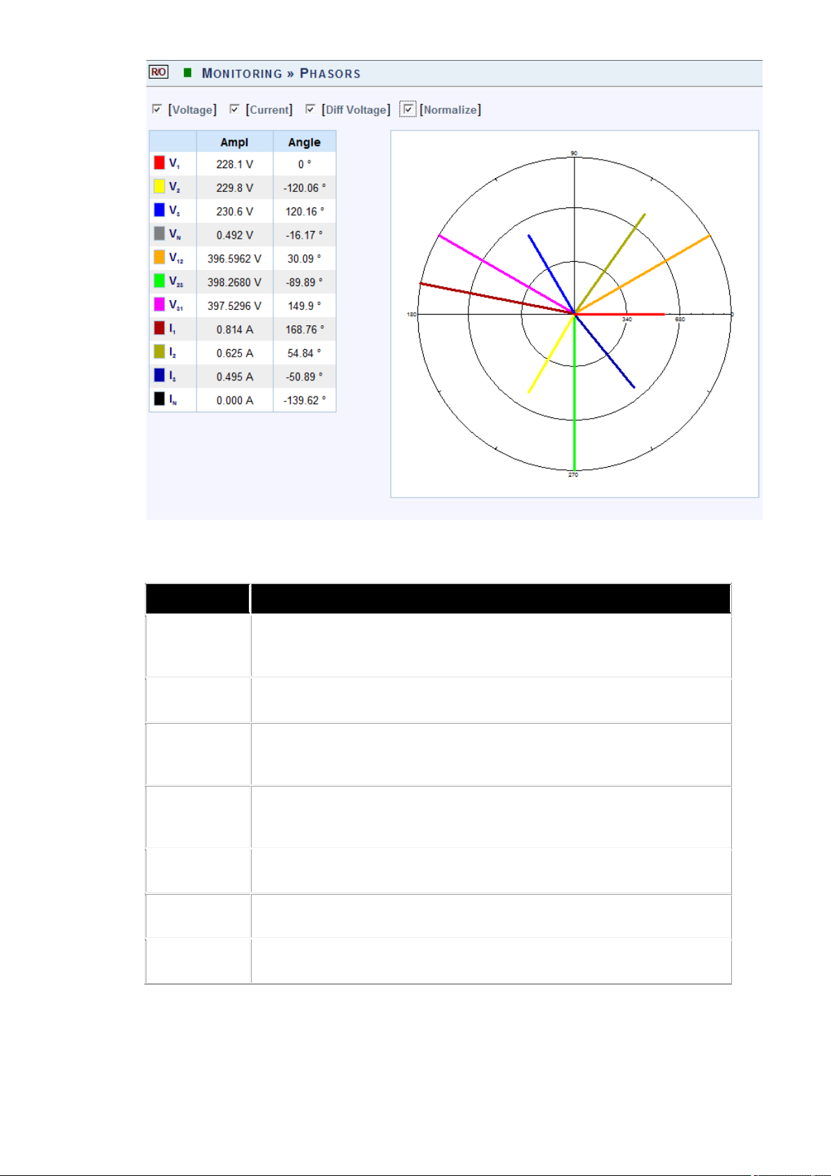
The Phasor Window will now open:
P
D
Displays Voltage Phase to Neutral Phasor (only p resent with
Displays the Phase to Phase Current (only present with Delta
The table outlines the sections' Parameter options (for your selection)
including their Definition:
ARAMETER
EFINITION
Voltage
WYE 4 Wire configuration)
Current Displays Phase Current
Diff
Displays the Phase to Neutral Voltages Phasor
Voltage
Diff
Current
3 Wire configuration)
Normalize Displays the all vector as part of the largest vector
Ampl The Amplitude of each Phasor
Angle V1 /V12 is at 0
Find Quality Products Online at: sales@GlobalTestSupply.com
www.GlobalTestSupply.com
0
, all other vectors are in relation to V1 /V12

CHART OPTIONS
Right-click o n the ch art to ac cess various options & capabilities f or t he
chart:
You may use the following chart options & capabilities:
Viewing Style: Different s tyling o ptions C olor / M onochrome ( B&W)
with/without Symbols / Bitmap etc. By selecting the option y ou can
view on screen the different styles available to you
Border Style: No Border, Thin Line, Shadow / Inset
Font Size: Large / Medium / Small
Show Legend: Display / Not display Legend
Plotting Method: From Line / Point / Point & Line
Data Shadows: Off / Shadow / 3D
Include Data Labels: Include / Exclude Numeric Data Labels
Mark Data Points: Mark/Unmark Data Points
Grid Options: Extend Radius Tick Marks, Both Degrees & Radius,
Degrees, Radius, Hid Grid Lines, Thin Grid Lines, Thick Grid Lines,
Dotted Grid Lines, Dashed Grid Lines & One Pixel Grid Lines
Maximize: Min / Max the Phasor Graph Only
84
Find Quality Products Online at: sales@GlobalTestSupply.com
ELSPEC GG44KK FFiixxeedd PPoowweerr QQuuaalliittyy AAnnaallyyzzeerr
UUSSEERR && IINNSSTTAALLLLAATTIIOONN GGUUIIDDE
E
www.GlobalTestSupply.com

Customization Dialog - Various General Graph Customization
Options (all options):
Export Dialog - Various Export Options:
85
Find Quality Products Online at: sales@GlobalTestSupply.com
ELSPEC GG44KK FFiixxeedd PPoowweerr QQuuaalliittyy AAnnaallyyzzeerr
UUSSEERR && IINNSSTTAALLLLAATTIIOONN GGUUIIDDE
E
www.GlobalTestSupply.com

SEE ALSO
Monitoring Real-Time Data
Voltage & Current Measurements
Average
Power
Temperature
Waveforms
Voltage Flickering
Pinst Waveform
Minimum / Maximum Flickering
Voltage & Current Harmonics
P & Q Harmonics
Spectrum
Harmonics Table
Voltage & Current, Min & Max Harmonics Table
PQ Min & Maximum Harmonics
Find Quality Products Online at: sales@GlobalTestSupply.com
www.GlobalTestSupply.com

Waveforms
The Waveform page displays the actual Voltage & Current waveforms monitored by
your G4K BLACKBOX Unit.
NOTE NOTE NOTE
In order to display the Phasor graph, ensure that you install the ActiveX plug-in
from G igasoft (downloadable e ither from Elspec's W ebsite's S upport S ection or
alternatively ca n b e in stalled d irectly f rom y our BLACKBOX C D). Y ou w ill
receive the following error message if the program is not installed:
For Internet Explorer 8/9 Users: Once y ou h ave in stalled G igasoft, e nsure
that the Internet Explorer is running in Compatibility View:
OPEN THE WAVEFORMS WINDOW
Access your G4K Unit via the Web Interface select Monitoring
Waveforms:
Find Quality Products Online at: sales@GlobalTestSupply.com
www.GlobalTestSupply.com

The Waveforms Window will now open:
P
D
Checking t he "A ll g raphs" b ox w ill a utomatically se lect a ll
Voltage &
Depending on y our p ower co nfiguration, y ou c an v iew al l
combinations o f p hase t o p hase a nd p hase t o l ine v oltage
lections i n th e
The table outlines the sections' Parameter options (for your selection)
including their Definition:
ARAMETER
Cycle Cycle Selection (1-4 Cycles)
All
the boxes below
Current
and c urrent c ombinations b y m aking s e
appropriate check boxes
EFINITION
Find Quality Products Online at: sales@GlobalTestSupply.com
www.GlobalTestSupply.com

CHART OPTIONS
By right-clicking on the chart you have various chart options & capabilities
available to you:
Viewing Style: Different styling options Color / Monochrome (B&W)
with/without Symbols / Bitmap etc. By selecting the option you can
view on screen the different styles available to you
Border Style: No Border, Thin Line, Shadow / Inset
Font Size: Large / Medium / Small
Display / Not display Legend
Numeric Precision: No up to 3 Decimals
Plotting Method: From Line / Bar / Point / Area / Spline /
Combinations
Data Shadows: Off / Shadow / 3D
Grid Options: Various grid options ranging from dots / lines /
different axis etc.
89
Find Quality Products Online at: sales@GlobalTestSupply.com
ELSPEC GG44KK FFiixxeedd PPoowweerr QQuuaalliittyy AAnnaallyyzzeerr
UUSSEERR && IINNSSTTAALLLLAATTIIOONN GGUUIIDDE
E
www.GlobalTestSupply.com

Graph & Table: Display either the graph / table / both:
Point Label Orientation: Auto / Vertical / Horizontal / Slanted
Mark Data Points: Displays data points on graph
Show Annotations: Displays annotations data descriptions
Zoom / Undo Zoom - Zoom in /out on your graph:
From the main Waveform window, select an area to zoom in.
Left-click and drag the mouse to define the area:
The enlarged area will now appear in the window
Zoom out by right/click & select Zoom out
Maximize: Maximize / Minimize graph
90
Find Quality Products Online at: sales@GlobalTestSupply.com
ELSPEC GG44KK FFiixxeedd PPoowweerr QQuuaalliittyy AAnnaallyyzzeerr
UUSSEERR && IINNSSTTAALLLLAATTIIOONN GGUUIIDDE
E
www.GlobalTestSupply.com

Customization Dialog - Various General Graph Customization
Options (all options apart from zooming above):
Export Dialog - Various Export Options:
91
Find Quality Products Online at: sales@GlobalTestSupply.com
ELSPEC GG44KK FFiixxeedd PPoowweerr QQuuaalliittyy AAnnaallyyzzeerr
UUSSEERR && IINNSSTTAALLLLAATTIIOONN GGUUIIDDE
E
www.GlobalTestSupply.com

SEE ALSO
Monitoring Real-Time Data
Voltage & Current Measurements
Average
Power
Temperature
Phasors
Voltage Flickering
Pinst Waveform
Minimum / Maximum Flickering
Voltage & Current Harmonics
P & Q Harmonics
Spectrum
Harmonics Table
Voltage & Current, Min & Max Harmonics Table
PQ Min & Maximum Harmonics
Find Quality Products Online at: sales@GlobalTestSupply.com
www.GlobalTestSupply.com

Voltage Flickering
Displays the short & long term Voltage Flickering to a v ery close approximation of
the EN50160 values.
OPEN THE VOLTAGE FLICKERING WINDOW
Access your G4K Unit via the Web Interface select Monitoring Voltage
Flickering:
The Voltage Flickering Window will now open:
Find Quality Products Online at: sales@GlobalTestSupply.com
www.GlobalTestSupply.com

The table outlines the sections' Parameter options (for your selection)
Flicker evaluation. T his measurement r eaches a very cl ose
including their Definition:
PARAMETER
PST INST
PSST 10
Sec.
PST
DEFINITION
Instantaneous f licker ev aluation. Output o f Bl ock 5 o f the
Flickermeter in Accordance with IEC61000-4-15 Edition 2
An E lspec m easurement d esigned to g et q uicker r esults r egarding
approximation of the EN50160 values, but in a fraction of the time.
The P SST is cal culated t he s ame as P ST b ut averaged o ver 10
seconds. T his E lspec d efined v alue is valuable in t hat it en ables
faster as sessment o f the f licker. E lspec P SST co nverges t o a r eal
value within 3 min from a drastic flicker change, or immediately for
periodic steady state flicker
Where t he P ercentiles , , , , are t he F licker L evels
Exceeded for 0.1, 1, 3, 10 & 50% of the Time During The Observation
Period. T he S uffix “ s” in t he F ormula I ndicates t hat t he S moothed
Value Should be Used. The Smoothed Values are Obtained Using the
Following Formulas:
P(1s) = (P(.7) + P(1) + P(1.5))/3
P(3s) = (P(2.2) + P(3) + P(4))/3
P(10s) = (P(6) + P(8) + P(10) + P(13) + P(17))/5
P(50s) = (P(30) + P(50) + P(80))/3
PST 10
Min
PLT
Short term flicker evaluation.
P
is a v alue m easured o ver 1 0 m inutes t hat c haracterizes t he
ST
likelihood that th e v oltage f luctuations w ould r esult i n p erceptible
light f licker. A v alue o f 1 .0 is d esigned t o r epresent t hat 5 0% o f
people would perceive flicker in a 60 watt incandescent bulb.
94
Find Quality Products Online at: sales@GlobalTestSupply.com
ELSPEC GG44KK FFiixxeedd PPoowweerr QQuuaalliittyy AAnnaallyyzzeerr
UUSSEERR && IINNSSTTAALLLLAATTIIOONN GGUUIIDDE
www.GlobalTestSupply.com
E

PARAMETER DEFINITION
Flicker ev aluation. This m easurement r eaches a v ery cl ose
lspec m easurement d esigned t o g ive better r esults r egarding
but averaged over 7 days, as
SPLT 1 Hour
PLT 2 Hour
LPLT 10
Hour
LPLT 7 Day
An Elspec measurement designed to get quicker results regarding
approximation o f t he EN 50160 v alues, b ut i n a f raction o f th e
time.
The SPLT is calculated the same as PLT but averaged over 1 hour.
This E lspec d efined v alue is v aluable i n t hat it e nables f aster
assessment of the flicker
The Long-Term PLT is Derived From the Short-Term Values Over 12
Short-Term Values of 10 Minutes Each Over a Period of 2 hours
An E lspec measurement d esigned to give better results r egarding
Flicker ev aluation b y u sing a l onger av eraging t ime. T he L PLT is
calculated the same as P
but averaged over 10 hours to allow a
LT
quicker "long term" average
An E
Flicker evaluation by using a longer averaging time.
The LPLT is calculated the same as PLT
per EN50160 parts 4-15
Reset all Flickering measurements of your G4K Unit
SEE ALSO
Monitoring Real-Time Data
Voltage & Current Measurements
Average
Power
Temperature
Phasors
Waveforms
Pinst Waveform
Minimum / Maximum Flickering
Voltage & Current Harmonics
P & Q Harmonics
Spectrum
Harmonics Table
Voltage & Current, Min & Max Harmonics Table
PQ Min & Maximum Harmonics
Find Quality Products Online at: sales@GlobalTestSupply.com
www.GlobalTestSupply.com

Pinst Wave form
Pinst is instantaneous flicker sensation that the G4K calculates for every selected
channel.
OPEN THE PINST WAVEFORM WINDOW
Access your G4K Unit via the Web Interface select Monitoring Pinst
Waveforms:
The Pinst Waveforms Window will now open:
96
Find Quality Products Online at: sales@GlobalTestSupply.com
ELSPEC GG44KK FFiixxeedd PPoowweerr QQuuaalliittyy AAnnaallyyzzeerr
UUSSEERR && IINNSSTTAALLLLAATTIIOONN GGUUIIDDE
E
www.GlobalTestSupply.com

The table outlines the sections' Parameter options (for your selection)
Select t he applicable ch annel f or F lickering W aveform
including their Definition:
PARAMETER DEFINITION
All
Checking the "All graphs" box will automatically select all
the boxes below
Voltage
Channels
display.
SEE ALSO
Monitoring Real-Time Data
Voltage & Current Measurements
Average
Power
Temperature
Phasors
Waveforms
Voltage Flickering
Minimum / Maximum Flickering
Voltage & Current Harmonics
P & Q Harmonics
Spectrum
Harmonics Table
Voltage & Current, Min & Max Harmonics Table
PQ Min & Maximum Harmonics
97
Find Quality Products Online at: sales@GlobalTestSupply.com
ELSPEC GG44KK FFiixxeedd PPoowweerr QQuuaalliittyy AAnnaallyyzzeerr
UUSSEERR && IINNSSTTAALLLLAATTIIOONN GGUUIIDDE
E
www.GlobalTestSupply.com

Minimum / Maximum Flickering
Displays the minimum & maximum short & long term Voltage Flickering vales to a
very close approximation of the EN50160 values.
OPEN THE MIN/MAX FLICKERIN G WINDOW
Access your G4K Unit via the Web Interface select Monitoring
Min/Max Flickering:
The Min/Max Flickering Window will now open:
98
Find Quality Products Online at: sales@GlobalTestSupply.com
ELSPEC GG44KK FFiixxeedd PPoowweerr QQuuaalliittyy AAnnaallyyzzeerr
UUSSEERR && IINNSSTTAALLLLAATTIIOONN GGUUIIDDE
E
www.GlobalTestSupply.com

The table outlines the sections' Parameter options (for your selection) including
Flicker ev aluation. T his m easurement reaches a v ery cl ose
their Definition:
PARAMETER DEFINITION
PST INST
PSST 10 Sec.
PST
Instantaneous f licker ev aluation. Output o f Bl ock 5 o f the
Flickermeter in Accordance with IEC61000-4-15 Edition 2
An E lspec m easurement d esigned t o g et quicker r esults r egarding
approximation of the EN50160 values, but in a fraction of the time.
The P SST i s calculated the sa me as P ST b ut av eraged over 1 0
seconds. T his E lspec d efined v alue is v aluable i n t hat i t en ables
faster as sessment o f the f licker. E lspec P SST co nverges t o a r eal
value within 3 min from a drastic flicker change, or immediately for
periodic steady state flicker
Where t he Percentiles , , , , are t he F licker L evels
Exceeded for 0.1, 1, 3, 10 & 50% of the Time During The Observation
Period. T he S uffix “ s” i n the F ormula I ndicates tha t th e Smoothed
Value S hould b e Used. The S moothed V alues are Obtained U sing the
Following Formulas:
P(1s) = (P(.7) + P(1) + P(1.5))/3
P(3s) = (P(2.2) + P(3) + P(4))/3
P(10s) = (P(6) + P(8) + P(10) + P(13) + P(17))/5
P(50s) = (P(30) + P(50) + P(80))/3
PST 10 Min Short term flicker evaluation.
P
is a v alue m easured over 1 0 m inutes t hat ch aracterizes the
ST
likelihood t hat t he v oltage f luctuations w ould r esult in p erceptible
light f licker. A v alue o f 1 .0 is d esigned t o r epresent that 5 0% o f
people would perceive flicker in a 60 watt incandescent bulb.
PLT
Where (i = 1 , 2, 3 , ...) a re C onsecutive Readings of t he S hort-
Term Severity
Find Quality Products Online at: sales@GlobalTestSupply.com
99
ELSPEC GG44KK FFiixxeedd PPoowweerr QQuuaalliittyy AAnnaallyyzzeerr
UUSSEERR && IINNSSTTAALLLLAATTIIOONN GGUUIIDDE
www.GlobalTestSupply.com
E

PARAMETER DEFINITION
r ev aluation. T his m easurement reaches a v ery cl ose
An E lspec m easurement d esigned t o g ive b etter r esults r egarding
An E lspec m easurement d esigned t o g ive b etter r esults r egarding
over 7 days, as per
SPLT 1 Hour
PLT 2 Hour
LPLT 10 Hour
LPLT 1 Day
LPLT 7 Day
An E lspec m easurement d esigned t o g et quicker r esults r egarding
Flicke
approximation of the EN50160 values, but in a fraction of the time.
The S PLT is calculated t he s ame as PLT b ut averaged over 1 h our.
This E lspec d efined value is v aluable i n t hat it enables f aster
assessment of the flicker
The Lo ng-Term PLT is D erived F rom the S hort-Term V alues O ver 1 2
Short-Term Values of 10 Minutes Each Over a Period of 2 hours
An E lspec m easurement d esigned t o g ive b etter r esults r egarding
Flicker ev aluation b y u sing a l onger av eraging t ime. T he L PLT is
calculated t he same as P
but av eraged over 1 0 h ours t o al low a
LT
quicker "long term" average
Flicker evaluation by using a longer averaging time.
The LPLT is calculated the same as P
but averaged over 1 day
LT
Flicker evaluation by using a longer averaging time.
The LPLT is calculated the same as PLT but averaged
EN50160 parts 4-15
Reset all Flickering measurements of your G4K Unit
SEE ALSO
Monitoring Real-Time Data
Voltage & Current Measurements
Average
Power
Temperature
Phasors
Waveforms
Voltage Flickering
Pinst Waveform
Voltage & Current Harmonics
P & Q Harmonics
Spectrum
Harmonics Table
Voltage & Current, Min & Max
Harmonics Table
PQ Min & Maximum Harmonics
Minimum / Maximum Flickering
100
Find Quality Products Online at: sales@GlobalTestSupply.com
ELSPEC GG44KK FFiixxeedd PPoowweerr QQuuaalliittyy AAnnaallyyzzeerr
UUSSEERR && IINNSSTTAALLLLAATTIIOONN GGUUIIDDE
E
www.GlobalTestSupply.com
 Loading...