

Elson Zircon 190 S Ind, Zircon 250 S Ind, Zircon 300 S Ind, Zircon 210 S Ind Installation & Servicing Instructions Manual
Page 1
1
Pack Contents
• Zircon Solar unvented water heater incorporating immersion heater(s) & thermal controls
• Factory tted temperature/pressure relief valve (set at 90°C / 1 Mpa (10bar))
• Cold water combination valve assembly
• Expansion vessel & mounting bracket
• Tundish
• 2 Port motorised valve
• Compression nuts & olives
• Immersion heater spanner
• Installation & servicing instructions
• Guarantee card
IMPORTANT
Please read & understand all these instructions before commencing installation.
Please leave this manual with the customer for future reference.
Zircon Installation Manual
Unvented Solar Indirect Water Heaters
Installation & Servicing Instructions
Page 2

2
Introduction....................................................................2
General Requirements...................................................3
Installation General........................................................5
Installation Discharge....................................................7
Installation Solar...........................................................11
Installation Auxiliary Heating Coil................................12
Commissioning............................................................14
Maintenance................................................................15
User Instructions..........................................................16
Fault Finding & Servicing.............................................17
Spares.........................................................................18
Heat Loss.....................................................................19
Environmental Information...........................................19
Commissioning Check List..........................................20
Service Record............................................................21
Warranty......................................................................24
Technical Support........................................................24
Contents
The cylinder is a purpose designed unvented water
heater. The unit has a stainless steel inner vessel,
which ensures an excellent standard of corrosion
resistance. The outer casing is a combination of
resilient thermoplastic mouldings and plastic coated
corrosion proofed steel sheet. All products are
insulated with CFC free polyurethane foam to give
good heat loss performance. (see Table 06, page 19)
The unit is supplied complete with all the necessary
safety and control devices needed to allow connection
to the cold water mains. All these components are
preset and not adjustable.
This appliance complies with the requirements of the
CE marking directive and is Kiwa approved to show
compliance with Building Regulations (Section G3).
The following instructions are offered as a guide to
installation which must be carried out by a competent
plumbing and electrical installer in accordance with
Building Regulation G3, The Building Standards
(Scotland) Regulations 1990, or The Building
Regulations (Northern Ireland).
NOTE: Prior to installation the unit should be stored
in an upright position in an area free from excessive
damp or humidity.
THE BENCHMARK SCHEME
Benchmark places responsibilities on both manufacturers and installers. The purpose is to ensure that customers are provided with the correct equipment for their
needs, that it is installed, commissioned and serviced
in accordance with the manufacturer’s instructions by
competent persons and that it meets the requirements
of the appropriate Building Regulations and relevant
electrical qualications. The Benchmark Checklist
can be used to demonstrate compliance with Building
Regulations and should be provided to the customer
for future reference. Installers are required to carry
out installation, commissioning and servicing work in
accordance with the Benchmark Code of Practice which
is available from the Heating and Hotwater Industry
Council who manage and promote the Scheme. Visit
www.centralheating.co.uk for more information.
Introduction
Page 3
3
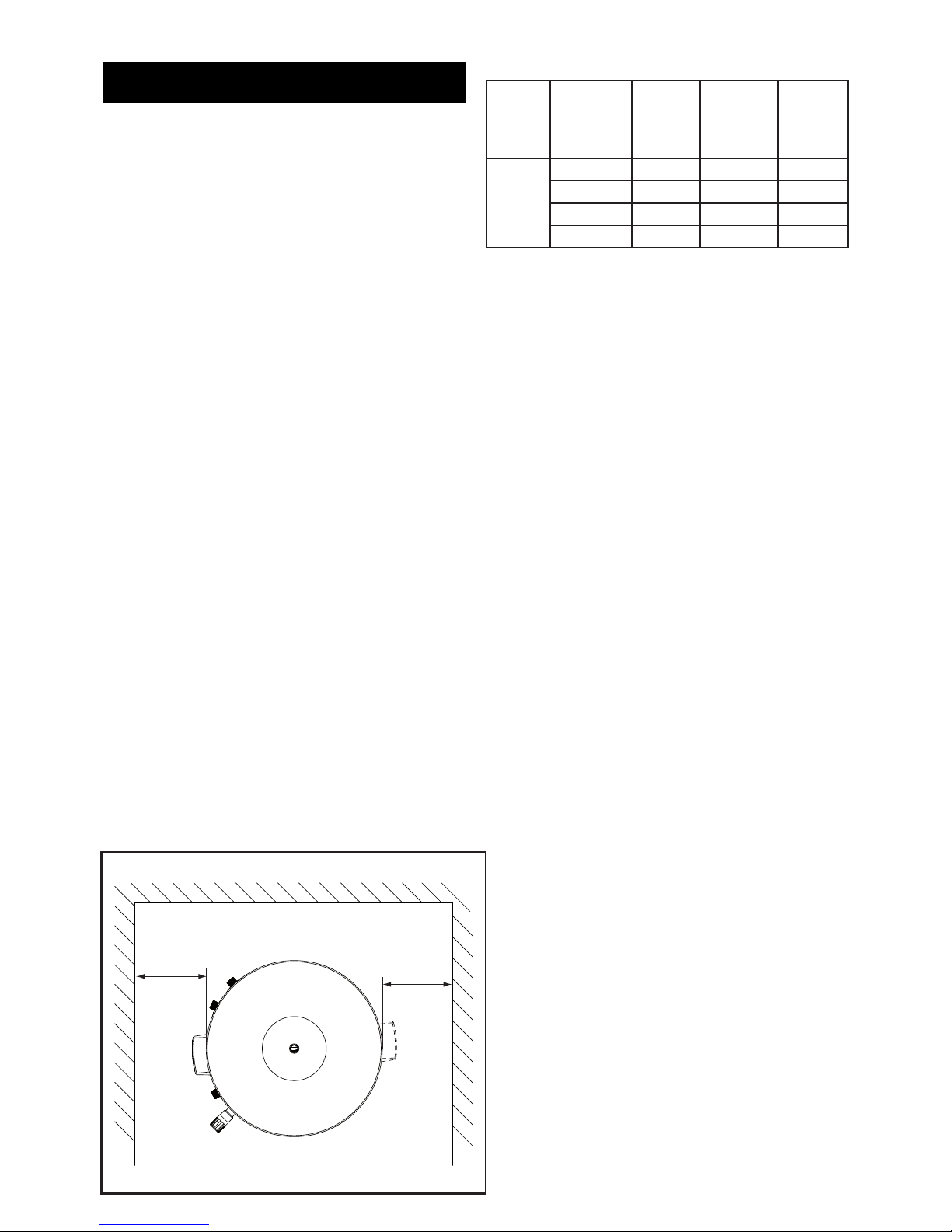
WALL
Min 250mm
Min 250mm
IMPORTANT:
This appliance can be used by children aged
from 8 years and above and persons with
reduced physical sensory or mental capabilities
or lack of experience and knowledge if they
have been given supervision or instruction
concerning use of the appliance in a safe way
and understand the hazards involved. Children
shall not play with the appliance. Cleaning
and user maintenance shall not be made by
children without supervision.
Children must be supervised to ensure they
do not play with the appliance.
WARNING: Do not switch on if there is a possibility that
the water in the heater is frozen.
Siting the Unit
The cylinder must be vertically oor mounted. Although
location is not critical, the following points should be
considered:
• The cylinder should be sited to ensure minimum
dead leg distances, particularly to the point of most
frequent use.
• Avoid siting where extreme cold temperatures will
be experienced. All exposed pipe work should be
insulated.
• The discharge pipework from the safety valves
must have minimum fall of 1:200 from the unit and
terminate in a safe and visible position.
• Access to associated controls and immersion
heaters must be available for the servicing and
maintenance of the system. Where these controls
are installed against a wall a minimum distance of
250mm must be left (see Fig. 01, below).
• Ensure that the oor area for the cylinder is level
and capable of permanently supporting the weight
when full of water. (see Table 01)Water Supply
Water supply
Bear in mind that the mains water supply to the
property will be supplying both the hot and cold water
requirements simultaneously.
It is recommended that the maximum water
demand is assessed and the water supply checked
to ensure this demand can be satisfactorily met.
Note: A high mains water pressure will not always
guarantee high ow rates.
Wherever possible the mains supply pipe should be
22mm. We suggest the minimum supply requirements
should be 0.15MPa (1.5 bar) pressure and 20 litres
per minute owrate. However, at these values outlet
ow rates may be poor if several outlets are used
simultaneously. The higher the available pressure and
ow rate the better the system performance.
The cylinder has an operating pressure of 0.35MPa (3.5
bar) which is controlled by the cold water combination
valve assembly. The cold water combination valve
assembly can be connected to a maximum mains
pressure of 1.6MPa (16 bar).
Outlet/Terminal Fittings (Taps, Etc)
The cylinder can be used with most types of terminal
ttings. It is advantageous in many mixer showers to
have balanced hot and cold water supplies. In these
instances a balanced pressure cold water connection
is available on the cold water combination valve
assembly (see Fig. 02, page 5). Outlets situated higher
than the cylinder will give outlet pressures lower than
that at the heater, a 10m height difference will result in
a 0.1MPa (1 bar) pressure reduction at the outlet. All
ttings, pipework and connections must have a rated
pressure of at least 0.6MPa (6 bar) at 80°C.
General Requirements
Table 01: Unit weights
Fig. 01: Siting the Unit
Type
Model
Reference
Nominal
Capacity
(litres)
Weight of
unit full
(Kg)
Weight
of unit
(Kg)
Solar
Indirect
190 S Ind 190 243 43
210 S Ind 210 264 50
250 S Ind 250 308 51
300 S Ind 300 367 58
Page 4

4
Limitations
The cylinder should not be used in association with
any of the following:
• Solid fuel boilers or any other boiler in which the
energy input is not under effective thermostatic
control, unless additional and appropriate safety
measures are installed.
• Ascending spray type bidets or any other class
1 back syphonage risk requiring that a type A air
gap be employed.
• Steam heating plants unless additional and
appropriate safety devices are installed.
• Situations where maintenance is likely to be
neglected or safety devices tampered with.
• Water supplies that have either inadequate pressure
or where the supply may be intermittent.
• Situations where it is not possible to safely pipe
away any discharge from the safety valves.
• In areas where the water consistently contains a
high proportion of solids, e.g. suspended matter
that could block the strainer, unless adequate
ltration can be ensured.
• In areas where the water supply contains chloride
levels that exceed 250mg/l.
Important Note:
THE SOLAR CYLINDER MUST BE INCORPORATED
INTO A FULLY PUMPED SOLAR PRIMARY
CIRCUIT.
CONTROL OF THE SOLAR PRIMARY CIRCUIT IS
ACHIEVED BY THE USE OF EXTERNAL CONTROLS
NOT SUPPLIED WITH THE UNIT. CONTROL MUST
BE A PURPOSE DESIGNED SOLAR DIFFERENTIAL
TEMPERATURE CONTROLLER.
Checklist
• Unvented cylinder
• Cold control pack
- Tundish
- Combination valve
- Expansion vessel
- Tool - Element spanner
- Compression nuts & olives
- 2 Port motorised valve
• Literature pack
- Installation manual
- Guarantee card
Operational Summary
Maximum mains pressure 1.6MPa (16 bar)
Operating pressure / PRV 0.35MPa (3.5 bar)
Maximum design pressure 0.6MPa (6 bar)
Expansion vessel charge pressure 0.35MPa (3.5 bar)
Expansion relief valve setting 0.6MPa (6 bar)
T&P relief valve setting 90-95°C/1.0MPa (10 bar)
Maximum primary circuit pressure 0.3MPa (3 bar)
(Auxiliary coil)
Maximum primary circuit pressure 0.3MPa (3 bar)
(Solar coil)
Pressure drop (Auxiliary coil) 0.02MPa (0.2 bar)
Pressure drop (Solar coil) 0.02MPa (0.2 bar)
Storage capacity See Table 1 - page 3
Weight when full See Table 1 - page 3
All models in conformance with BS EN 12897:2006
Note: Although the primary coil pressure rating is 1.0Mpa (10 bar) the 2 port zone valve supplied with the
cylinder is only rated 0.86MPa (8.6 bar). If the cylinder is to be plumbed into a system delivering 1.0MPa (10
bar) a suitable 2 port zone valve will have to be sourced.
Page 5
5
Pipe Fittings
All pipe ttings are made via 22mm compression ttings
directly to the unit. The ttings are threaded 3/4”BSP
male parallel, should threaded pipe connections be
required.
Cold Feed
A 22mm cold water supply is recommended, however,
if a 15mm (1/2”) supply exists, which provides sufcient
ow, this may be used (although more ow noise may
be experienced). A stopcock or servicing valve should
be incorporated into the cold water supply to enable the
cylinder and its associated controls to be isolated and
serviced.
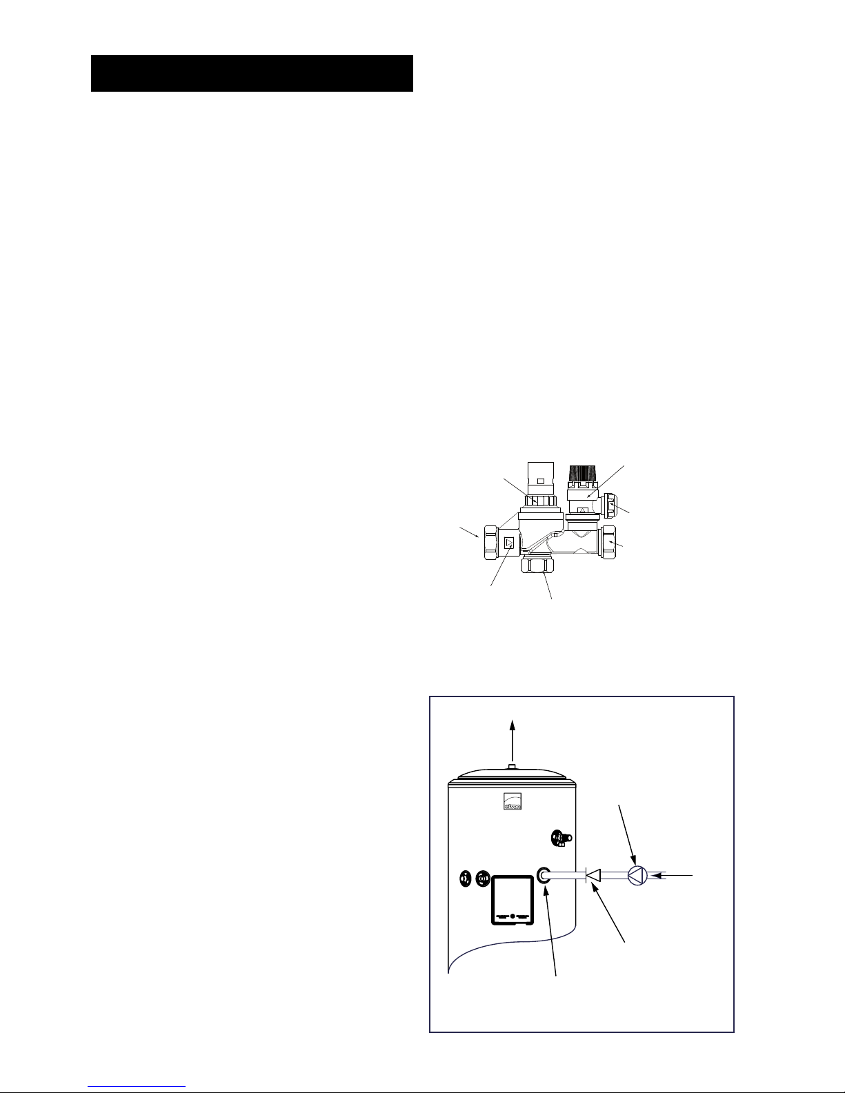
Cold Water Combination Valve Assembly
The 1-piece cold water combination valve assembly
(see Fig. 02 opposite) can be located anywhere on the
cold water mains supply prior to the expansion vessel
(see Fig. 06 Page 10). The cold water combination
valve is installed as a complete one-piece unit. The
valve incorporates the pressure reducer, strainer,
expansion valve and check valve. Ensure that the valve
is installed with the direction of ow arrows pointing
in the correct direction. No other valves should be
placed between the cold water combination valve and
the cylinder.
Drain Tap
A suitable drain tap should be installed in the cold water
supply to the cylinder between the expansion valve (see
Fig. 06 Page 10) and the heater at as low a level as
possible. It is recommended that the outlet point of the
drain pipework be at least 1 metre below the level of
the heater (this can be achieved by attaching a hose
to the drain tap outlet spigot).
Expansion Vessel
The expansion vessel accommodates expansion that
results from heating the water inside the unit. The
expansion vessel is pre-charged at 0.35MPa (3.5 bar).
The expansion vessel must be connected between
the expansion valve and the cylinder (see Fig. 06
Page 10). The location of the expansion vessel should
allow access to recharge the pressure as and when
necessary, this can be done using a normal car foot
pump. It is recommended that the expansion vessel
is adequately supported. An expansion vessel wall
mounting bracket is supplied for this purpose and
should be tted.
Secondary Circulation
If secondary circulation is required it is recommended
that it be connected to the cylinder as shown (see
Fig. 03 below) The secondary return pipe should
be in 15mm pipe and incorporate a check valve to
prevent backow. A suitable WRAS approved bronze
circulation pump will be required. On large systems,
due to the increase in system water content, it may be
necessary to t an additional expansion vessel to the
secondary circuit. This should be done if the capacity
of the secondary circuit exceeds 10 litres.
Pipe capacity (copper):
15mm O.D. = 0.13 l/m (10 litres = 77m)
22mm O.D. = 0.38 l/m (10 litres = 26m)
28mm O.D. = 0.55 l/m (10 litres = 18m)
Outlet
The hot water outlet is a 22mm compression tting
located at the top of the cylinder. Hot water distribution
pipework should be 22mm pipe with short runs of
15mm pipe to terminal ttings such as sinks and basins.
Pipe sizes may vary due to system design.
Installation General
Fig. 03: Secondary Circulation Connection
SECONDARY
CIRCULATION
PUMP
SECONDARY
RETURN
CHECK VALVE
SECONDARY RETURN
CONNECTION
HOT OUTLET
Expansion valve
(6bar)
Cold mains
connection
(22mm)
Expansion valve
outlet (15mm)
Outlet connection
(22mm)
Direction of
flow
Balanced take
off port
Pressure reducing
valve cartridge
(3.5bar)
Fig. 02: Cold Water Combination Valve Assembly
Page 6
6
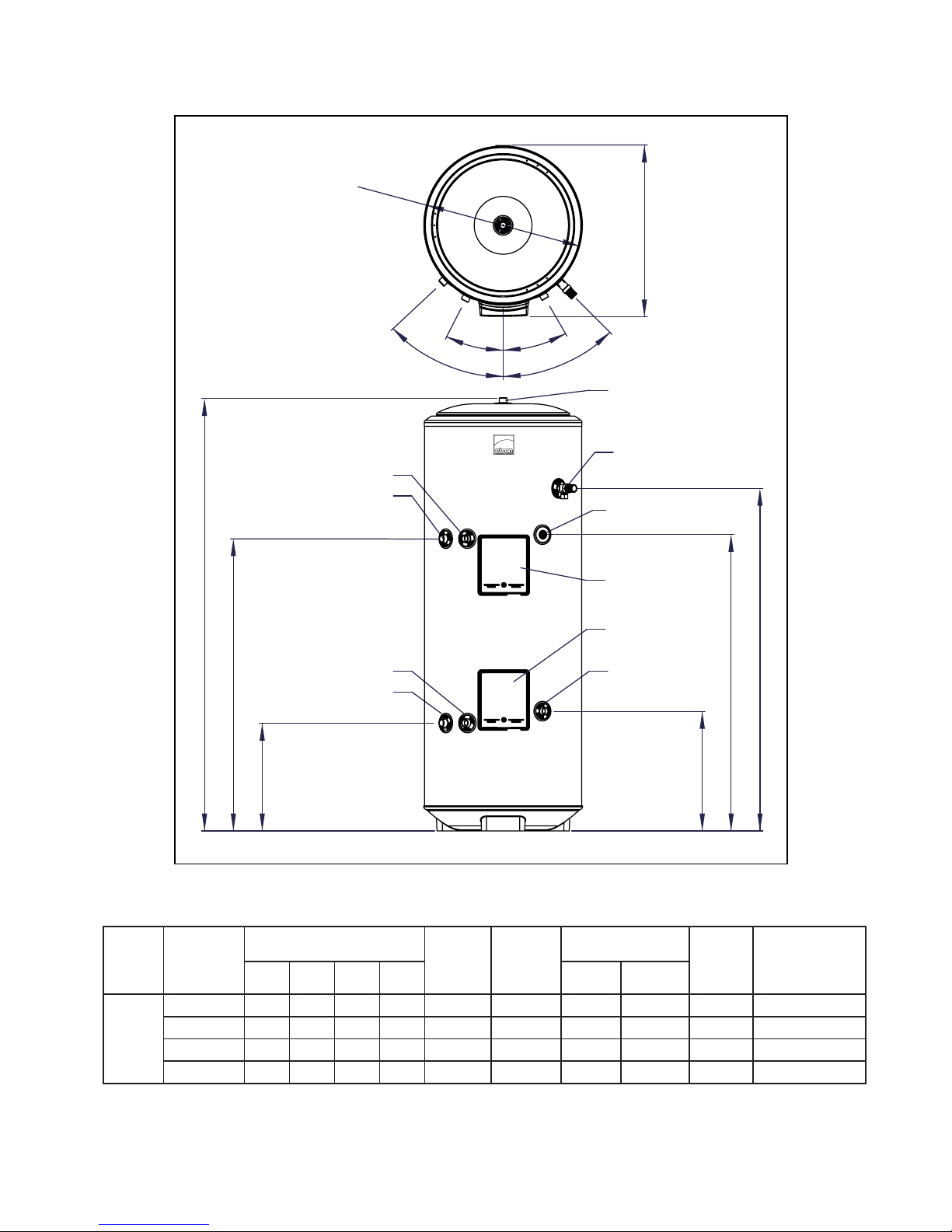
Fig. 04 General Dimensions
Notes:
1. Indirect cylinders tested in conformance with BS EN 12897:2006
2. Heat up time from cold through 45°C, with a primary ow rate 15ltrs/min at 80°C +/- 2°C.
Table 02: Dimensions and Performance
Type Model
Reference
Dimensions (mm) Solar
Volume
(ltrs)
Auxiliary
Volume
(ltrs)
Coil Rating (kW) Heat-up
Time
(mins)
Hot Water
Capacity (ltrs)
(volume of water
drawn off >40°C)
A B C D Solar Auxiliary
Solar
Indirect
190 S Ind 1401 1085 784 925 65 120 19 14.2 32 132
210 S Ind 1499 1186 1012 1026 85 120 19 15.0 25 196
250 S Ind 1752 1438 1143 1279 95 145 19 15.2 30 237
300 S Ind 2065 1752 1440 1592 120 175 19 17.4 32 265
D
B
373
C
A
415
SOLAR RETURN
SOLAR FLOW COLD INLET
HOT OUTLET
T&P VALVE
AUXILIARY RETURN
AUXILIARY FLOW
45°
25°
30°
45°
592
Ø
550
SOLAR CONTROL
AUXILLARY
CONTROL
SECONDARY RETURN
Page 7

7
Discharge Pipework
It is a requirement of Building Regulation G3 that
any discharge from an unvented system is conveyed
to where it is visible, but will not cause danger to
persons in or about the building. The tundish and
discharge pipes should be tted in accordance with the
requirements and guidance notes of Building Regulation
G3. The G3 Requirements and Guidance section 3.50
- 3.63 are reproduced in the following sections of this
manual. For discharge pipe arrangements not covered
by G3 guidance advice should be sought from your
local Building Control Ofcer. Any discharge pipe
connected to the pressure relief devices (expansion
valve and temperature/pressure relief valve) must be
installed in a continuously downward direction and in
a frost free environment.
Water may drip from the discharge pipe of the
pressure relief device. This pipe must be left open to
the atmosphere. The pressure relief device is to be
operated regularly to remove lime deposits and to
verify that it is not blocked.
G3 REQUIREMENT
“...there shall be precautions...to ensure that the
hot water discharged from safety devices is safely
conveyed to where it is visible but will not cause danger
to persons in or about the building.”
The following extract is taken from the latest G3
Regulations
Discharge pipes from safety devices
Discharge pipe D1
3.50 Each of the temperature relief valves or combined
temperature and pressure relief valves specied in 3.13
or 3.17 should discharge either directly or by way of
a manifold via a short length of metal pipe (D1) to a
tundish.
3.51 The diameter of discharge pipe (D1) should be
not less than the nominal outlet size of the temperature
relief valve.
3.52 Where a manifold is used it should be sized to
accept and discharge the total discharge form the
discharge pipes connected to it.
3.53 Where valves other than the temperature and
pressure relief valve from a single unvented hot water
system discharge by way of the same manifold that
is used by the safety devices, the manifold should be
factory tted as part of the hot water storage system
unit or package.
Tundish
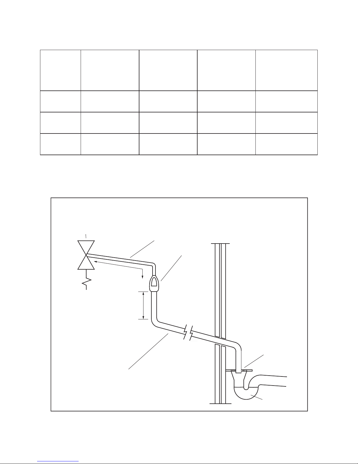
3.54 The tundish should be vertical, located in the same
space as the unvented hot water storage system and
be tted as close as possible to, and lower than, the
valve, with no more than 600mm of pipe between the
valve outlet and the tundish (see Fig. 05 page 9 ).
Note: To comply with the Water Supply (Water Fittings)
Regulations, the tundish should incorporate a suitable
air gap.
3.55 Any discharge should be visible at the tundish. In
addition, where discharges from safety devices may
not be apparent, e.g. in dwellings occupied by people
with impaired vision or mobility, consideration should
be given to the installation of a suitable safety device
to warn when discharge takes place, e.g. electronically
operated.
Discharge pipe D2
3.56 The discharge pipe (D2) from the tundish
should:
(a) have a vertical section of pipe at least 300mm
long below the tundish before any elbows or bends in
the pipework (see Fig. 05 page 9); and
(b) be installed with a continuous fall thereafter of at
least 1 in 200.
3.57 The discharge pipe (D2) should be made of:
(a) metal; or
(b) other material that has been demonstrated to
be capable of safely withstanding temperatures of
the water discharged and is clearly and permanently
marked to identify the product and performance
standard (e.g. as specied in the relevant part of BS
7291).
3.58 The discharge pipe (D2) should be at least one
pipe size larger than the nominal outlet size of the
safety device unless its total equivalent hydraulic
resistance exceeds that of a straight pipe 9m long,
i.e. for discharge pipes between 9m and 18m the
equivalent resistance length should be at least two
sizes larger than the nominal outlet size of the safety
device; between 18 and 27m at least 3 sizes larger, and
so on; bends must be taken into account in calculating
the ow resistance (see Table 03 page 9) and the
worked example.
Note: An alternative approach for sizing discharge
pipes would be to follow Annex D, section D.2 of
BS 6700:2006 Specication for design, installation,
testing and maintenance of services supplying water
for domestic use within buildings and their curtilages.
3.59 Where a single common discharge pipe serves
more than one system, it should be at least one pipe
size larger than the largest individual discharge pipe
(D2) to be connected.
Installation Discharge
Page 8

8
3.60 The discharge pipe should not be connected to
a soil discharge stack unless it can be demonstrated
that the soil discharge stack is capable of safely
withstanding temperatures of the water discharged,
in which case, it should:
(a) contain a mechanical seal, not incorporating a
water trap, which allows water into the branch pipe
without allowing foul air from the drain to be ventilated
through the tundish;
(b) be a separate branch pipe with no sanitary
appliances connected to it;
(c) if plastic pipes are used as branch pipes carrying
discharge from a safety device they should be either
polybutalene (PB) to Class S of BS 7291-2:2006 or
cross linked polyethylene (PE-X) to Class S of BS
7291-3:2006; and
(d) be continuously marked with a warning that no
sanitary appliances should be connected to the pipe.
Note:
1. Plastic pipes should be joined and assembled
with ttings appropriate to the circumstances in which
they are used as set out in BS EN ISO 1043-1.
2. Where pipes cannot be connected to the stack it
may be possible to route a dedicated pipe alongside
or in close proximity to the discharge stack.
Termination of discharge pipe
3.61 The discharge pipe (D2) from the tundish should
terminate in a safe place where there is no risk to
persons in the vicinity of the discharge.
3.62 Examples of acceptable discharge arrangements
are:
(a) to a trapped gully with the end of the pipe below
a xed grating and above the water seal;
(b) downward discharges at low level; i.e. up to
100mm above external surfaces such as car parks,
hard standings, grassed areas etc. are acceptable
providing that a wire cage or similar guard is positioned
to prevent contact, whilst maintaining visibility; and
(c) discharges at high level: e.g. into a metal hopper
and metal downpipe with the end of the discharge pipe
clearly visible or onto a roof capable of withstanding
high temperature discharges of water and 3m from
any plastic guttering system that would collect such
discharges.
3.63 The discharge would consist of high temperature
water and steam. Asphalt, roofing felt and non-
metallic rainwater goods may be damaged by such
discharges.
Worked Example of Discharge Pipe Sizing
Fig. 05: shows a G1/2 temperature relief valve with a
discharge pipe (D2) having 4 No. elbows and length of
7m from the tundish to the point of discharge.
From Table 03:
Maximum resistance allowed for a straight length of
22mm copper discharge pipe (D2) from a G1/2
temperature relief valve is 9.0m.
Subtract the resistance for 4 No. 22mm elbows at 0.8m
each = 3.2m
Therefore the permitted length equates to: 5.8m
5.8m is less than the actual length of 7m therefore
calculate the next largest size.
Maximum resistance allowed for a straight length of
28mm pipe (D2) from a G1/2 temperature relief valves
equates to 18m.
Subtract the resistance of 4 No. 28mm elbows at 1.0m
each = 4.0m
Therefore the maximum permitted length equates to:
14m
As the actual length is 7m, a 28mm (D2) copper pipe
will be satisfactory.
WARNINGS:
• Under no circumstances should the factory tted
temperature/pressure relief valve be removed other
than by a competent person. To do so will invalidate
any guarantee or claim.
• The cold water combination valve assembly must be
tted on the mains water supply to the cylinder.
• No control or safety valves should be tampered with
or used for any other purpose.
• The discharge pipe should not be blocked or used for
any other purpose.
• The tundish should not be located adjacent to any
electrical components.
Page 9
9
Table 03: Sizing of copper discharge pipe (D2) for common temperature relief valve outlet sizes
NOTE: The table below is based on copper tube. Plastic pipes may be of different bore and resistance. Sizes and
maximum lengths of plastic should be calculated using data prepared for the type of pipe being used.
VALVE OUTLET
SIZE
MINIMUM SIZE OF
DISCHARGE PIPE D1
MINIMUM SIZE OF
DISCHARGE PIPE D2
FROM TUNDISH
MAXIMUM RESISTANCE
ALLOWED, EXPRESSED
AS A LENGTH OF
STRAIGHT PIPE (I.E. NO
ELBOWS OR BENDS
RESISTANCE CREATED BY
EACH ELBOW OR BEND
G 1/2 15MM 22mm
28mm
35mm
UP TO 9M
UP TO 18M
UP TO 27M
0.8M
1.0M
1.4M
G 3/4 22MM 28mm
35mm
42mm
UP TO 9M
UP TO 18M
UP TO 27M
1.0M
1.4M
1.7M
G 1 28MM 35mm
42mm
54mm
UP TO 9M
UP TO 18M
UP TO 27M
1.4M
1.7M
2.3M
600mm maximum
300mm
minimum
Safety device
(e.g. Temperature
relief valve)
Metal discharge pipe (D1) from
Temperature relief valve to tundish
Tundish
Discharge below
fixed grating
(Building Regulation
G3 section 3.61 gives
alternative points
of discharge)
Fixed grating
Trapped
gully
Discharge pipe (D2) from tundish,
with continuous fall. See Building
Regulation G3 section 3.56,
Table 03 and worked example
Figure 05: Typical Discharge Pipe Arrangment (Extract From Building Regulation G3 Guidance Section 5.50)
Page 10
10
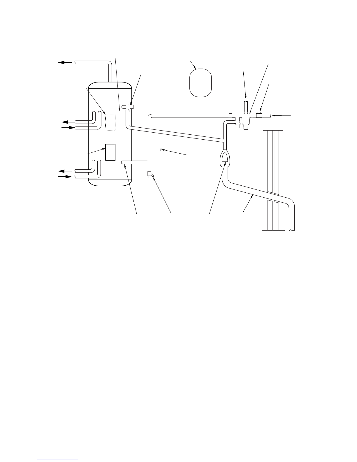
Fig. 06: Typical SOLAR Installation - Schematic
To hot outlets
Solar
Primary flow
Solar
Primary return
T&P relief
valve
Expansion
vessel
Balanced cold
water connection
(if required)
Cold water
combination
valve
Mains water
supply
Isolating valve
(not supplied)
Discharge
pipe
Tundish
Drain cock
(not supplied)
Secondary return
(if required)
use swept tee
Inlet
Boost element/
Auxillary
control housing
Solar
controls
housing
Auxillary
Primary return
Auxillary
Primary flow
Solar
Primary return
o
Secondary
Return Tapping
(if required)
Page 11
11
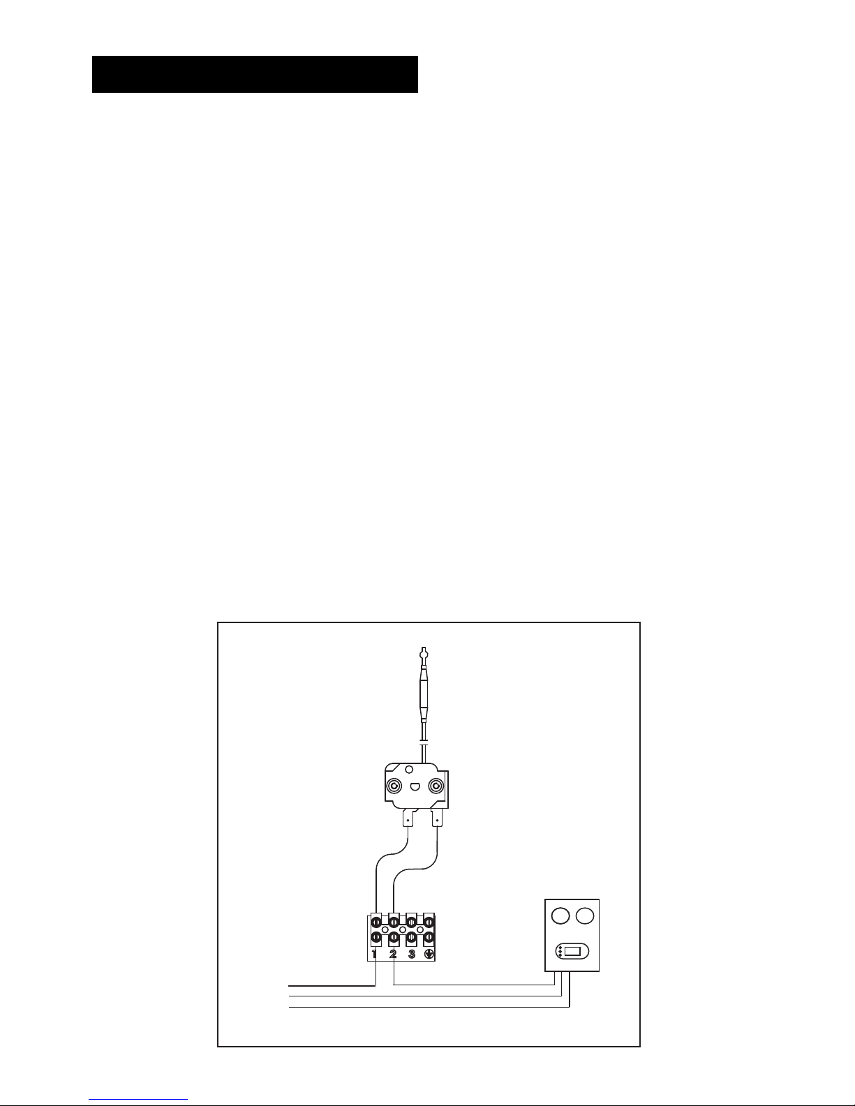
Fig. 07: Solar Control Connections
Installation - Solar
Connection To Solar Primary Circuit
The lower (solar) coil of the SOLAR cylinder must be
connected to a fully pumped solar primary circuit. The
connections are suitable for 22mm copper pipe direct
to the compression ttings provided. The connections
are also threaded 3/4” BSP male parallel should BSP
be required.
The solar primary circuit should have its own dedicated
circulating pump and safety controls which must be
installed as per the manufacturer’s instructions.
Control of Solar Primary Circuit
Temperature control of the SOLAR cylinder must be
carried out using a suitable proprietory solar controller/
programmer. The cylinder temperature sensing probe
(supplied with the solar controller) should be fully
inserted with the thermal cut-out probe into the pocket
provided on the SOLAR cylinder.The cable must
be secured using the cable clamps on the controls
housing.
Connection to the solar controller should be in
accordance with the manufacturers instructions.
The solar controller should be programmed to give a
cylinder temperature of approximately 60°C (maximum
70°C).
THERMAL CUT-OUT
PROBE
CONTROL ASSEMBLY
POWER SUPPLY TO
SOLAR CONTROLLER
L
N
E
SOLAR CONTROLLER
The solar controller and solar primary circulation
pump must be wired via the over-temperature cut-out
mounted in the lower solar controls housing. This will
ensure that the heat input to the solar coil is interrupted
in the event of the cylinder over-heating (see Fig. 07
below). There must also be suitable check (non-return)
valves installed in the solar primary ow and return to
prevent the possibility of any thermo-syphoning if the
solar circulation is stopped.
Page 12
12
Safety
DISCONNECT FROM THE MAINS ELECTRICAL
SUPPLY BEFORE REMOVING ANY COVERS.
Never attempt to replace the immersion heater other
than with the recommended authorised immersion
heater(s).
DO NOT BYPASS THE THERMAL CUT-OUT(S) IN
ANY CIRCUMSTANCES. Ensure the two male spade
terminations on the combined thermostat and thermal
cut-out are pushed firmly onto the corresponding
terminations on the element assembly.
In case of difculty contact service support; contact
details available at the back of this booklet.
Electrical Supply
All electrical wiring should be carried out by a
competent electrician and be in accordance with the
latest I.E.E Wiring Regulations.
Each circuit must be protected by a suitable fuse
and double pole isolating switch with a contact
separation of at least 3mm in both poles.
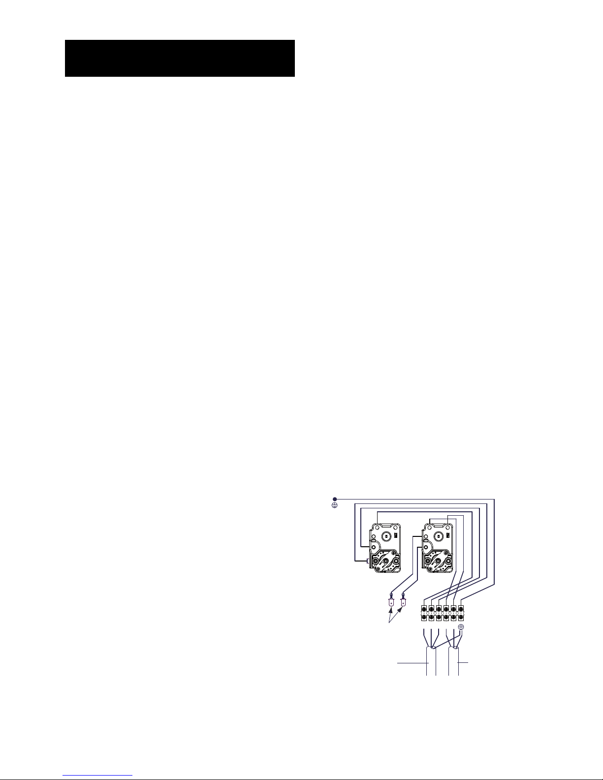
The immersion heater should be wired in accordance
with Fig 08 opposite. The immersion heaters MUST be
earthed. The supply cable should be 1.5mm2 3 core
HO5 VV-F sheathed and must be routed through the
cable grip provided with the outer sheath of the cable
rmly secured by tightening the screws on the cable
grip.
DO NOT operate the immersion heaters until the
cylinder has been lled with water.
Ensure the thermostat and thermal cut-out sensing
bulbs are pushed fully into the pockets on the element
plate assembly.
Plumbing Connections
Indirect cylinders require the following
pipework connections.
• Cold water supply to and from inlet controls.
• Outlet to hot water draw off points.
• Discharge pipework from valve outlets to
tundish.
• Connection to the primary circuit.
All connections are 22mm compression. However,
3/4”BSP parallel threaded ttings can be tted to the
primary coil connections if required.
Boiler Selection
The boiler should have a control thermostat and non
self-resetting thermal cut-out and be compatible with
unvented storage water heaters.
Where use of a boiler without a thermal cut-out is
unavoidable a “low head” open vented primary circuit
should be used. The feed and expansion cistern head
above the cylinder should not exceed 2.5m.
Primary Circuit Control
The 2 port motorised valve supplied with the cylinder
MUST be tted on the primary ow to the cylinder heat
exchanger (coil) and wired in series with the indirect
control thermostat and thermal cut-out tted to the
unit. (see Fig. 08 below). Primary circulation to the
cylinder heat exchanger (coil) must be pumped; gravity
circulation WILL NOT WORK.
Space and Heating Systems Controls
The controls provided with the cylinder will ensure the
safe operation of the unit within the central heating
system. Other controls (eg. room thermostat and
timer) will be necessary to control the space heating
requirements and times that the system is required to
function.The cylinder is compatible with most heating
controls, examples of electrical circuits are shown in
Figs. 09 and 10 (Page 13). However, other systems
may be suitable, refer to the controls manufacturers’
instructions, supplied with the controls selected, for
alternative system wiring schemes.
Installation -
Auxiliary Heating Coil
Fig. 08: Electrical Connections
L
N
1 2 3
Control Housing Details
Element Connections
1.5mm² 3 Core
HO5 VV-F sheathed
cable
Indirect control
wiring
Page 13
13
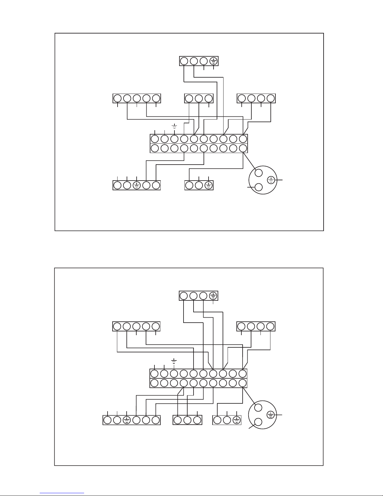
Fig. 09: Schematic Wiring Diagram - Basic 2 x 2 port valve system ( ‘S’ plan )
Fig. 10: Schematic Wiring Diagram - 3 port mid position valve system, ( ‘Y’ plan ). N.B. Must be used in conjunction
with 2 port zone valve supplied
NOTES: Control terminal numbering may differ from those shown.
Refer to instructions with controls selected.
A double pole isolating switch must be installed in the mains supply.
All earth connections must be connected back to the mains earth supply.
L1N
2
3
HTGONDHW
ON
L
N
2
3
1
L2N
3
4
5 6 7 8 9 10
1
2 3
4
5 6 7 8 9 10
(Supply)
1
2 3
G
1
Br
Bl20 GY
3
G1Br Bl20
1
3 2
2
L
N
Programmer Boiler Pump
Zone valve (HTG)
Cylinder terminal block
Room stat
Zone valve (DHW)
(supplied)
Junction box
3
2
3
L1N
2
3
HTGONDHW
ON
L
N
2
3
1
L2N
3
4
5 6 7 8 9 10
1
2 3
4
5 6 7 8 9 10
(Supply)
1
2 3
G
W
Bl20 GY
3
G1Br Bl20
L
N
Programmer Boiler Pump
3 Port Zone valve
Cylinder terminal block
1
3 2
2
Room stat
Zone valve (DHW)
(supplied)
Junction box
NOTES: Control terminal numbering may differ from those shown.
Refer to instructions with controls selected.
A double pole isolating switch must be installed in the mains supply.
All earth connections must be connected back to the mains earth supply.
3
DHW
OFF
2
3
Page 14
14
Filling The Unit With Water
Ensure that all ttings and immersion heaters are
correctly tted and tightened. An immersion heater key
is provided to aid tightening the immersion heater(s)
• Check expansion vessel pre-charge pressure. The
vessel is supplied precharged to 0.35MPa (3.5
bar) to match the control pressure of the pressure
reducing valve. The precharge pressure is checked
using a car tyre gauge by unscrewing the plastic
cap opposite the water connection.
• Check all connections for tightness including the
immersion heater(s). An immersion heater key
spanner is supplied for this purpose.
• Ensure the drain cock is CLOSED.
• Open a hot tap furthest from the cylinder.
• Open the mains stop cock to ll the unit. When
water ows from the tap, allow to run for a few
minutes to thoroughly ush through any residue,
dirt or swarf, then close the tap.
• Open successive hot taps to purge the system
of air.
System Checks
• Check all water connections for leaks and rectify
as necessary.
• Turn off mains water supply.
• Remove the pressure reducing valve head work to
access the strainer mesh, clean and re-t.
• Turn mains water supply on.
• Manually open, for a few seconds, each relief
valve in turn, checking that water is discharged
and runs freely through the tundish and out at the
discharge point.
• Ensure that the valve(s) reseat satisfactorily.
Solar Primary Circuit
Fill the solar primary circuit following the instructions
provided with the solar hydraulic controls. The cylinder
temperature control probe supplied with the solar
controller must be fully inserted into the pocket in the
lower controls housing and the cable securely clamped.
Heating by the solar primary circuit is controlled by the
solar controller; refer to the manufacturer’s installation
instructions for details of how to set up and connect
the solar primary circuit. The solar controller should be
programmed to give a maximum storage temperature
in the cylinder of 70°C, (60°C is recommended to
minimise scaling).
Secondary heating coil
Fill the secondary circuit following the boiler
manufacturer’s commissioning instructions. To ensure
the cylinder primary heat exchanger is lled, the 2
port motorised valve (supplied) should be manually
opened by moving the lever on the motor housing to
the MANUAL setting. When the primary circuit is full
return the lever to the AUTOMATIC position.
Switch on the boiler, ensure the programmer is set to
Domestic Hot Water and allow the cylinder to heat up to
a normal working temperature (60°C recommended). If
necessary the temperature can be adjusted by inserting
a at bladed screwdriver in the adjustment knob (located
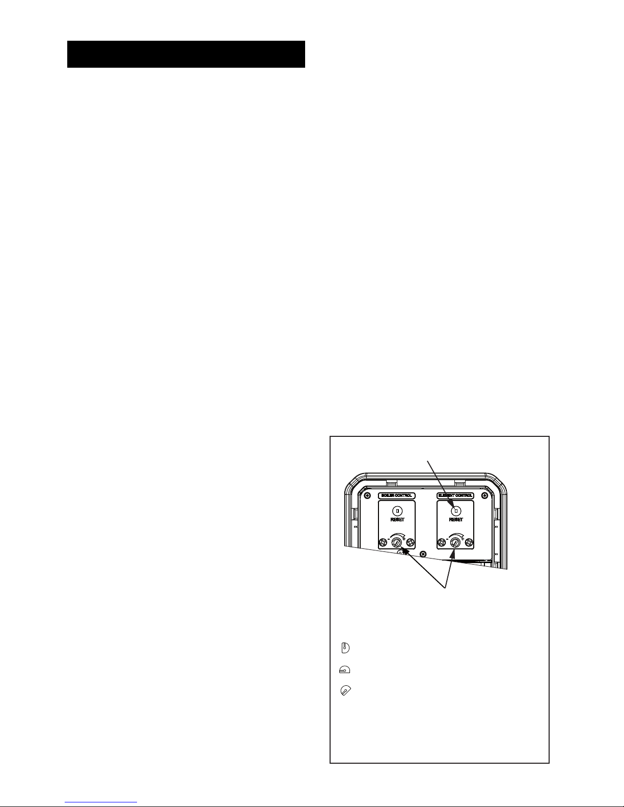
on front of the thermostat mounting bracket - (see Fig.11
below) and rotating. The minimum thermostat setting
is 10°C.
The adjustment represents a temperature range of 10°C
to 72°C.
Check the operation of the indirect thermostat and 2
port motorised valve and that no water has emitted from
the expansion relief valve or temperature/pressure relief
valve during the heating cycle.
Benchmark Log Book
On completion of the installation and commissioning
procedures detailed in this manual the Benchmark
Installation, Commissioning and Service Record Log,
pages 20 and 21 should be completed and signed off
by the competent installer or commissioning engineer
in the relevant sections. The various system features,
location of system controls, user instructions and what
to do in the event of a system failure should be explained
to the customer. The customer should then countersign
the BenchmarkTM Commissioning Checklist (page 20)
to accept completion. The service record should be
lled in when any subsequent service or maintenance
operation is carried out on the product.
Commisioning
Fig. 11: Indirect Thermostat and Thermal Cut-out
SPINDLE POSITIONS
= MINIMUM TEMP 10ºC
= MAXIMUM TEMP 72ºC
= APPROX 60 °C
ROTATE SPINDLE CLOCKWISE
FOR TEMPERATURE INCREASE
AND COUNTER CLOCKWISE
FOR TEMPERATURE DECREASE
THERMAL CUT-OUT RESET BUTTON
TEMPERATURE ADJUSTING
SPINDLE
Page 15

15
Maintenance Requirements
Unvented hot water systems have a continuing
maintenance requirement in order to ensure safe
working and optimum performance. It is essential
that the relief valve(s) are periodically inspected and
manually opened to ensure no blockage has occurred
in the valves or discharge pipework.
Similarly cleaning of the strainer element and
replacement of the air in the expansion vessel will help
to prevent possible operational faults.
The maintenance checks described below should be
performed by a competent person on a regular basis,
e.g. annually to coincide with boiler maintenance.
After any maintenance, please complete the relevant
Service Interval Record section of the Benchmark
Checklist on Page 21 of this document.
Inspection
The immersion heater boss can be used as an access
for inspecting the cylinder internally.
Safety Valve Operation
Manually operate the temperature/pressure relief valve
for a few seconds. Check water is discharged and that it
ows freely through the tundish and discharge pipework.
Check valve reseats correctly when released.
NOTE: Water discharged may be very hot!
Repeat the above procedure for the expansion relief
valve.
Strainer
Turn off the cold water supply, boiler and immersion
heaters. The lowest hot water tap should then be
opened to de-pressurise the system. Remove the
pressure reducing cartridge to access the strainer
mesh. Wash any particulate matter from the strainer
under clean water. Re-assemble ensuring the seal
is correctly fitted. DO NOT use any other type of
sealant.
Descaling Immersion Heater
Before removing the immersion heater the unit must be
drained. Before draining ensure the water, electrical
supply and boiler are OFF. Attach a hosepipe to the
drain cock having sufcient length to take water to a
suitable discharge point below the level of the unit.
Open a hot tap close to the unit and open drain cock to
drain unit. Remove the cover to the immersion heater
housing and disconnect wiring from immersion heater.
Carefully remove the thermostat capillaries. Note. the
order of the capillaries within the pocket. Remove the
terminal shroud. Unscrew immersion heater backnut
and remove immersion heater from the unit. A key
spanner is supplied with the cylinder unit for easy
removal/tightening of the immersion heater.
Over time the immersion heater gasket may become
stuck to the mating surface. To break the seal insert a
round bladed screwdriver into one of the pockets on
the immersion heater and gently lever up and down.
Carefully remove any scale from the surface of the
element. DO NOT use a sharp implement as
damage to the element surface could be caused.
Ensure sealing surfaces are clean and seals are
undamaged, if in doubt t a new gasket
(part number 70 351 65).
Replace immersion heater ensuring the (right angled)
element hangs vertically downwards towards the base
of the unit. It may be helpful to support the immersion
heater using a round bladed screwdriver inserted
into one of the thermostat pockets whilst the backnut
is tightened. Replace the terminal shroud. Connect
wiring to element. Check, and close and secure
immersion heater housing cover.
Expansion Vessel Charge Pressure
While system is de-pressurised check expansion
vessel charge pressure. Remove the dust cap on
top of the vessel. Check the charge pressure using
a tyre pressure gauge. The pressure (with system de-
pressurised) should be 0.35MPa (3.5 bar). If it is lower
than the required setting it should be re-charged using
a tyre pump (Schrader valve type). DO NOT OVERCHARGE. Re-check the pressure and when correct
replace the dust cap.
Re-commissioning
Check all electrical and plumbing connections are
secure. Close the drain cock. DO NOT switch on
the immersion heater(s) or boiler while the unit
is empty. With a hot tap open, turn on the cold water
supply and allow unit to rell. When water ows from the
hot tap allow to ow for a short while to purge air and
ush through any disturbed particles. Close hot tap and
then open successive hot taps in system to purge any
air. When completely full and purged check system for
leaks. Replace and secure immersion heater housing
cover. The heating source (immersion heater or boiler)
can then be switched on.
Maintenance
Page 16

16
User instructions
Warnings
IF WATER DISCHARGES FROM THE TEMPERATURE/
PRESSURE RELIEF VALVE ON CYLINDER SHUT
DOWN THE BOILER. ISOLATE ELECTRICAL SUPPLY
TO THE IMMERSION HEATER.
DO NOT TURN OFF ANY WATER SUPPLY. CONTACT
A COMPETENT INSTALLER FOR UNVENTED WATER
HEATERS TO CHECK THE SYSTEM.
DO NOT TAMPER WITH ANY OF THE SAFETY VALVES
FITTED TO THE SYSTEM. IF A FAULT IS SUSPECTED
CONTACT A COMPETENT INSTALLER.
Benchmark
The cylinder is covered by the Benchmark Scheme
which aims to improve the standards of installation
and commissioning of domestic heating and hot water
systems in the UK and to encourage regular servicing
to optimise safety, efciency and performance.
Benchmark is managed and promoted by the Heating
and Hotwater Industry Council. For more information
visit www.centralheating.co.uk.
Please ensure that the installer has fully completed the
Benchmark Checklist (Pages 20 & 21) of this manual
and that you have signed it to say that you have received
a full and clear explanation of its operation. The installer
is legally required to complete a commissioning checklist
as a means of complying with the appropriate Building
Regulations (England & Wales).
All installations must be notied to Local Area
Building Control either directly or through a
Competent Persons Scheme. A Building Regulations
Compliance Certicate will then be issued to the
customer who should, on receipt, write the
Notication Number on the Benchmark Checklist.
This product should be serviced regularly to optimise
its safety, efciency and performance. The service
engineer should complete the relevant Service Record
on the Benchmark Checklist after each service.
The Benchmark Checklist may be required in the event
of any warranty work.
Flow Performance
When initially opening hot outlets a small surge in
ow may be noticed as pressures stabilise. This is
quite normal with unvented systems. In some areas
cloudiness may be noticed in the hot water. This is
due to aeration of the water, is quite normal and will
quickly clear.
Temperature Controls - Solar
Temperature control of the solar primary coil is by
means of solar differential temperature controller. This
will usually have been set during commissioning to give
a storage temperature of approximately 60°C. Refer to
user instructions supplied with the controller for details
of how to adjust this if required.
DO NOT bypass the thermal cut-out(s) in any
circumstances.
Temperature Controls
The cylinder units are tted with an indirect control
thermostat and thermal cut-out. These controls must
be wired in series with the 2 port motorised zone valve
supplied to interrupt the ow of primary water around
the heat exchanger coil when the control temperature
has been reached. The controls are located within
the upper terminal housing along with the immersion
heater thermostat. The thermostat is factory set to
give a water storage temperature of approx. 55°C
to 60°C. Access to the thermostat can be made by
opening the terminal housing cover - DISCONNECT
THE ELECTRICAL SUPPLY BEFORE OPENING THE
COVER. Temperature adjustment is made by inserting
a at bladed screwdriver in the adjustment knob and
rotating. The minimum thermostat setting is 10°C. The
adjustment represents a temperature range of 10°C to
72°C (60°C recommended) ( Fig. 11, page 14). If in any
doubt contact a competent electrician.
An immersion heater is also provided for use should the
indirect heat source be shut down for any purpose. The
immersion heater control temperature is set using the
immersion heater thermostat.
DO NOT bypass the thermal cut-out(s) in any
circumstances.
Operational Faults
Operational faults and their possible causes are
detailed in the Fault Finding section of this book.
It is recommended that faults should be checked
by a competent installer. The air volume within the
expansion vessel will periodically require recharging
to ensure expanded water is accommodated within
the unit. A discharge of water INTERMITTENTLY from
the expansion valve will indicate the air volume has
reduced to a point where it can no longer accommodate
the expansion.
Page 17

17
Important
• After servicing, complete the relevant Service
Interval Record section of the Benchmark Checklist
located on page 21 of this document.
• Servicing should only be carried out by competent
persons in the installation and maintenance of
unvented water heating systems.
• Any spare parts used MUST be authorised
parts.
• Disconnect the electrical supply before removing
any electrical equipment covers.
• NEVER bypass any thermal controls or operate
system without the necessary safety valves.
• Water contained in the cylinder may be very
hot, especially following a thermal control failure.
Caution must be taken when drawing water from
the unit.
Fault Finding & Servicing
Table 04: Fault Finding Chart
Fault Possible Cause Remedy
No hot water ow
Mains supply off Check and open stop cock
Strainer blocked Turn off water supply. Remove strainer and
clean
Cold water combination valve incorrectly
tted
Check and ret as required
Water from hot tap
is cold
Direct immersion heater not switched on Check and switch on
Direct immersion heater thermal cut-out
has operated
Check, reset by pushing button on thermostat
Indirect programmer set to central heating only
Check, set to domestic hot water programme
Indirect boiler not working Check boiler operation. If fault is suspected
consult boiler manufacturer’s instructions
Indirect thermal cut-out has operated Check, reset by pushing button on thermostat
Check operation of indirect thermostat
Indirect motorised valve not connected
correctly
Check wiring and/or plumbing connections to
motorised valve
Water discharges
from expansion
valve
INTERMITTENTLY
Expansion vessel charge pressure has
reduced below 3.5 bar, or set to high
See maintenance section for re-charging of
expansion vessel procedure
CONTINUALLY
Cold water combination valve pressure
reducer not working correctly.
Expansion valve seat damaged
Check pressure from cold water combination
valve. If greater than 3.5 bar replace pressure
reducing valve
Remove expansion valve cartridge, check
condition of seat. If necessary t new expansion
valve
Water discharges
from T&P relief
valve
Thermal control failure
NOTE: water will be very hot
Switch off power to immersion heater(s) and
shut down boiler
DO NOT turn off water supply. When discharge
stops check all thermal controls, replace if faulty
Milky water
Oxygenated water Water from a pressurised system releases
oxygen bubbles when owing. The milkiness will
disappear after a short while
Spare Parts
A full range of spare parts are available for the
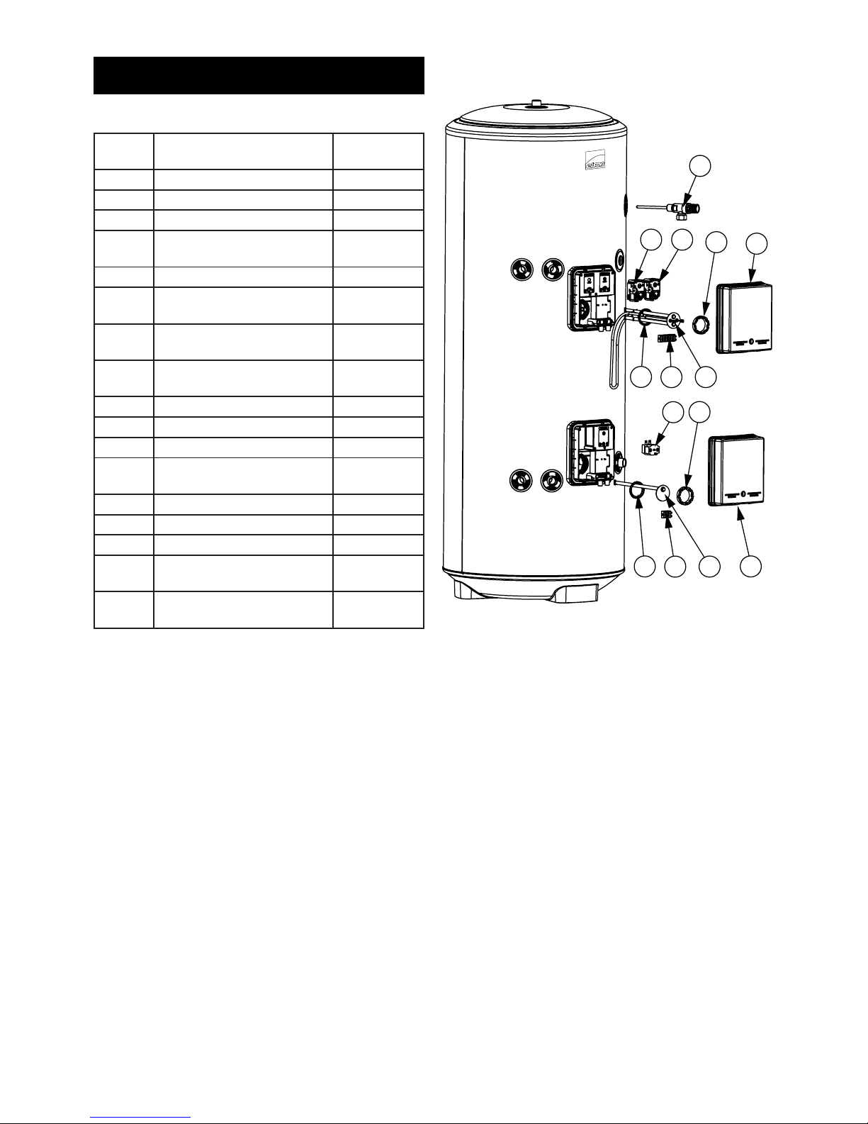
cylinder range (Table 05 Page 18). Refer to the
technical data label on the unit to identify the model
installed and ensure the correct part is ordered. You
will need to quote the serial number, which is printed
on the data label.
Fault Finding
The fault nding chart (Table 04 below) will enable
operational faults to be identied and their possible
causes rectied. Any work carried out on the unvented
water heater and its associated controls MUST be
carried out by a competent installer for unvented water
heating systems. In case of doubt contact service
support (see contact details on back page).
Warning
DO NOT TAMPER WITH ANY OF THE SAFETY VALVES
OR CONTROLS SUPPLIED WITH THE CYLINDER AS
THIS WILL INVALIDATE ANY GUARANTEE.
Page 18
18
Spares
Table 05: Spares
Fig. 12: Solar Cylinder Spares Diagram
16
8
7
3
10
2
11
1
2
15
13
9
3
10
Item
Number
Description Part Number
1 Immersion heater 95 606 961
2 Immersion heater gasket 70 351 65
3 Immersion heater backnut 95 607 869
4 Immersion heater key
spanner
95 607 861
5 Tundish 95 605 838
6 Cold water combination
valve - complete
70 344 68
7 Direct combined thermostat
and thermal cut-out
95 612 717
8 Indirect combined thermo-
stat and thermal cut-out
95 612 716
9 Thermal cut-out 95 612 698
10 Terminal cover 77 008 62
11 6 way terminal block 95 607 933
12 Accessory kit - Indirect
(without expansion vessel)
95 607 968
13 Solar pocket assembly 95 607 064
14 Expansion vessel - 24 litre 95 607 612
15 3 way terminal block 95 607 932
16 Temperature / pressure
relief valve
95 605 810
17 Pressure reducing catridge
3.5 Bar
70 360 63
Page 19
19
Table 06: Standing heat losses (based on an ambient air
temperature of 20°C and a stored water temperature of
65°C)
Products are manufactured from many recyclable
materials. At the end of their useful life they should be
disposed of at a Local Authority Recycling Centre in order
to realise the full environmental benets.
Insulation is by means of an approved CFC/HCFC free
polyurethane foam with an ozone depletion factor of zero.
WEEE Declaration
Disposal of Waste Equipment by Users in Private
Household in the European Union.
This symbol on the product indicates that this product
must not be disposed of with your other household waste.
Instead, it is your responsibility to dispose of your waste
equipment by handing it over to a designated collection
point for the recycling of waste electrical equipment.
The separate collection and recycling of your waste
equipment at the time of disposal will help to conserve
natural resources and ensure that it is recycled in a
manner that protects human health and the environment.
For more information about where you can drop off your
waste equipment for recycling, please contact your local
city ofce, your household waste disposal service or the
company where this product was purchased.
Heat Loss Environmental
Nominal
Capacity
(Litres)
Standing Heat Loss
per day
(kWh/24h)
per year
(kWh/365d)
190 1.65 642
210 1.75 664
250 1.98 670
300 2.31 843
Table: Technical parameters in accordance with European Commission regulations 814/2013 and 812/2013
Model(s) 190 210 250 300
Energy efficiency class C C C C
Storage volumes V in Litres 190.0 210.0 250.0 300.0
Standing loss in W 80.0 81.7 82.5 96.3
Table: Figures measured in accordance with KIWA Test
Criteria for compliance with UK Building and Water
Regulations
Page 20
20
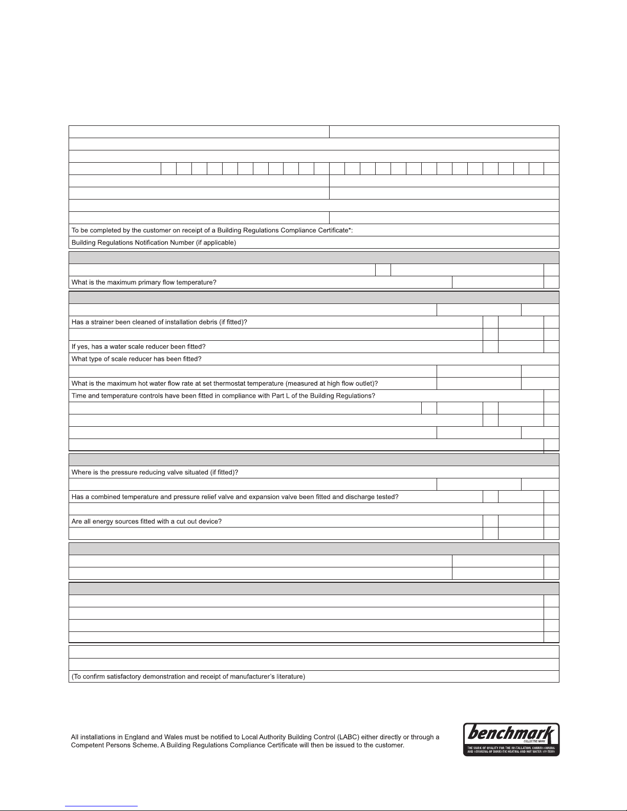
This Commissioning Checklist is to be completed in full by the competent person who commissioned the storage system as a means of
demonstrating compliance with the appropriate Building Regulations and then handed to the customer to keep for future reference.
Failure to install and commission this equipment to the manufacturer’s instructions may invalidate the warranty but does not affect statutory rights.
MAINS PRESSURE HOT WATER STORAGE SYSTEM COMMISSIONING CHECKLIST
Customer name: Telephone number:
Address:
Cylinder Make and Model
Cylinder Serial Number
Commissioned by (PRINT NAME): Registered Operative ID Number
Company name: Telephone number:
Company address:
Commissioning date:
ALL SYSTEMS PRIMARY SETTINGS (indirect heating only)
Is the primary circuit a sealed or open vented system? Sealed Open
°C
ALL SYSTEMS
What is the incoming static cold water pressure at the inlet to the system? bar
Yes No
Is the installation in a hard water area (above 200ppm)? Yes No
Yes No
What is the hot water thermostat set temperature? °C
I/min
Yes
Type of control system (if applicable) Y Plan S Plan Other
Is the cylinder solar (or other renewable) compatible? Yes No
What is the hot water temperature at the nearest outlet? °C
All appropriate pipes have been insulated up to 1 metre or the point where they become concealed Yes
UNVENTED SYSTEMS ONLY
What is the pressure reducing valve setting? bar
Yes No
The tundish and discharge pipework have been connected and terminated to Part G of the Building Regulations Yes
Yes No
Has the expansion vessel or internal air space been checked? Yes No
THERMAL STORES ONLY
What store temperature is achievable? °C
What is the maximum hot water temperature? °C
ALL INSTALLATIONS
The hot water system complies with the appropriate Building Regulations Yes
The system has been installed and commissioned in accordance with the manufacturer’s instructions Yes
The system controls have been demonstrated to and understood by the customer Yes
The manufacturer’s literature, including Benchmark Checklist and Service Record, has been explained and left with the customer Yes
Commissioning Engineer’s Signature
Customer’s Signature
*
© Heating and Hotwater Industry Council (HHIC)
www.centralheating.co.uk
Page 21

21
It is recommended that your hot water system is serviced regularly and that the appropriate Service Record is completed.
Service Provider
Before completing the appropriate Service Record below, please ensure you have carried out the service as described in the manufacturer’s instructions.
SERVICE RECORD
SERVICE 01
Date:
Engineer name:
Company name:
Telephone No:
Comments:
Signature
SERVICE 03
Date:
Engineer name:
Company name:
Telephone No:
Comments:
Signature
SERVICE 05
Date:
Engineer name:
Company name:
Telephone No:
Comments:
Signature
SERVICE 07
Date:
Engineer name:
Company name:
Telephone No:
Comments:
Signature
SERVICE 09
Date:
Engineer name:
Company name:
Telephone No:
Comments:
Signature
SERVICE 02
Date:
Engineer name:
Company name:
Telephone No:
Comments:
Signature
SERVICE 04
Date:
Engineer name:
Company name:
Telephone No:
Comments:
Signature
SERVICE 06
Date:
Engineer name:
Company name:
Telephone No:
Comments:
Signature
SERVICE 08
Date:
Engineer name:
Company name:
Telephone No:
Comments:
Signature
SERVICE 10
Date:
Engineer name:
Company name:
Telephone No:
Comments:
Signature
Email Address:
Email Address:
Email Address:
Email Address:
Email Address: Email Address:
Email Address: Email Address:
Email Address: Email Address:
Page 22

22
NOTES
Page 23

23
NOTES
Page 24

24
Fifers Lane, Norwich, Norfolk NR6 6XB
T: 0344 335 8819
F: 0344 871 1528
E: [email protected]
W: elsonhotwater.co.uk
36006103_issue_06
Sales & Support
Policy Statement
The policy of ELSON is one of
continuous product development
and, as such, we reserve the right to
change specications without notice.
Warranty
On site service support including
parts and labour for 12 months from
date of installation. After the initial 12
months, a guarantee will apply for
a further 24 years for the stainless
steel inner vessel only. During this 24
year period, in the event of a cylinder
leak, a replacement product will be
issued provided that the replacement
is carried out by one of our heateam
engineers, for which reasonable labour
charges will apply.
The Warranty is valid provided that:
• It has been correctly installed as
per the instructions contained
in the instruction manual and all
relevant Codes of Practice and
Regulations in force at the time of
installation.
• The Benchmark Checklist
has been completed upon
commissioning and the
Benchmark Service Record is
completed for each service.
• It has not been modied in any
way, other than by ELSON.
• It has not been frost damaged.
• It has only been used for the
storage of potable water.
• It has not been tampered with
or been subjected to misuse or
neglect.
• The fault is not scale related.
• Within 60 days of installation the
user completes and returns the
certicate supplied along with the
proof of purchase to register the
product.
• It has been installed in the United
Kingdom.
• The fault is not caused by high
chloride levels in the water supply
or incorrect disinfection methods.
Evidence of purchase and date
of supply may be required. The
guarantee is transferable. This
guarantee does not affect your
statutory rights.
Servicing
Baxi Customer Support
Baxi Customer Support is Elson’s
service division. With us on your side,
you can be sure that your customers
are in the very best of hands. Totally
committed to quality and safety, Baxi
Customer Support is open 7 days a
week, 363 days a year.
*excluding Christmas Day and New Year’s Day.
Simply call 0344 335 8819 or contact
us at [email protected]
• Dedicated Trade Advice
Line - our helpful and qualied
specialists are always on hand
to help you with even the most
complex technical query.
• Installer Priority Call-Outs - our
280 strong team of specically
trained expert heating engineers
covers the UK, no one is better
qualied to look after Elson’s
products for the duration of the
guarantee.
• Fully Stocked Vans - a
nationwide eet of vans, fully
stocked with spare parts -
meaning we can repair our
appliances on the rst visit 95% of
call-outs.
• Exclusive Service Plans -
heateam also offer Elson’s
customers a range of exclusive
annual service plans.
Opening Times: Monday-Friday 8am6pm, weekends and Bank Holidays*
8.30am-2pm.
*excluding Christmas Day and New Year’s Day.
Spares
For all technical support, replacement
parts & service issues please contact:
Electric Water Heating Co.
2 Horsecroft Place, Pinnacles,
Harlow, Essex CM19 5BT
Tel: 0845 0553811
E-mail: [email protected]
SPD
Special Product Division, Units 9 & 10
Hexagon Business Centre,
Springeld Road,
Hayes, Middlesex UB4 0TY
Tel: 020 8606 3567
Parts Center
Tel: 0845 270 9800
www.partscenter.co.uk
Newey & Eyre
Specialists Products Division
Please contact your local branch
UK Spares Ltd
Tower Lane, Warmley,
Bristol BS30 8XT
Tel: 0117 961 6670
www.uk-spares.com
Advanced Water Company Ltd
Unit 5D, Enterprise Way, Vale Park,
Evesham, Worcestershire WR11 1GS
Tel: 01386 760 066
 Loading...