

Page 1
Conduit angled diagonally
downwards (for cable access
from above or below)
Conduit angled vertically downwards (only
for cable access from above!)
concealed
concealed
45°
cable
cable
box
box
M16 conduit, 50 cm in length
M16 conduit,
50 cm in length
The display unit is held by magnets. Remove the front part from the concealed
box.
Caution: The display is connected
with a flat-ribbon cable to the circuit
board in the concealed box.
Loosen the plug so that the display unit
can be removed.
Remove all parts of the transportation
lock/packing.
The security covering in the concealed
box is attached with four screws: Loosen
the screws and take off the security covering.
Remove the circuit board from the concealed box to be installed a keep it in a place
where it is protected from dirt. It may ne-
ver be exposed to dust or moisture!
Place the concealed box in the wall so
that the arrows point upwards.
For fitting, screw the cover (board) on to
the concealed box with the enclosed
screws.
Clamp the concealed box to the wall with
the four enclosed screws.
Upon delivery, the pouch containing the
assembly screws can be found in the control unit’s concealed box.
or
Adjust the screws of the magnetic mounting with the enclosed template. Each of
the four screws must be adjusted individially in height.
When the edge of the template rests on
the wall surface (1), the template must
rest on the mounting screws as well (2).
1
1
2
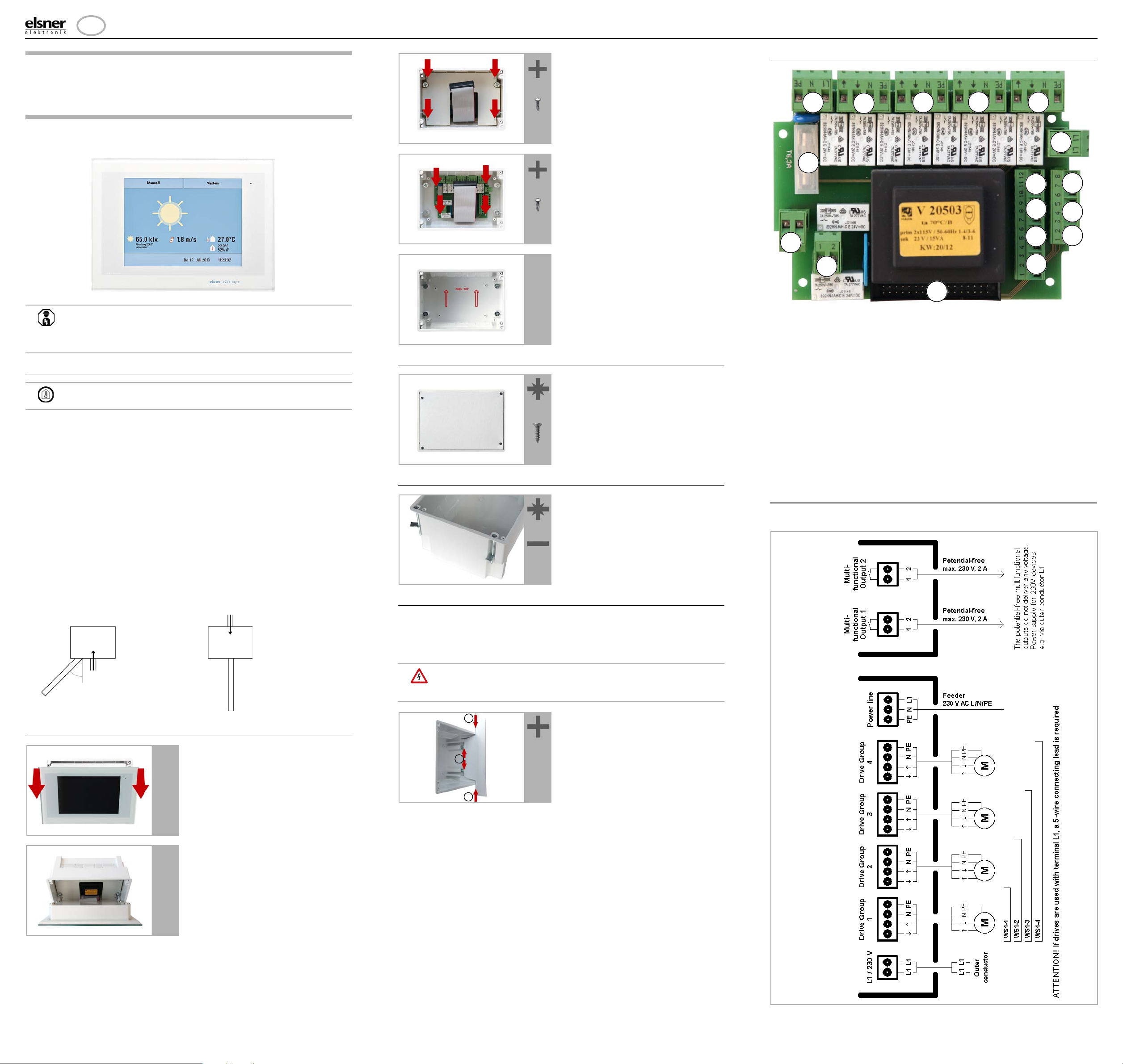
1 Mains connection
L/N/PE 230 V/50 Hz
2 Drive group 1
3 Drive group 2
4 Drive group 3
5 Drive group 4
6 Outer conductor L1
7 Multifunctional output 1
(potential-free)
8 MF output 2 (potential-free)
9 Wall button 1
(terminal 1: +12 V | 2: Up | 3: Down)
10 Wall button 2
(4: +12 V | 5: Up | 6: Down)
11 Wall button 3
(7: +12 V | 8: Up | 9: Down)
12 Wall button 4
(10:+12V|11:Up|12:Down)
13 Weather station (terminals 1-2)
14*Multifunctional input 1
(terminal 3: +12 V | 4: GND | 5: IN)
15*MF input 2 (6: +12 V | 7: GND | 8: IN)
16 Connector for flat-ribbon cable to
front board
17 Microfuse T6,3 A
* Supply voltage e. g. indoor sensor
possible via MF inputs
(No. 14, terminal 3(+), 4(-) and
No. 15, terminal 6(+), 7(-)),
max. 50 mA altogether.
1
2
3
4
5
6
7
8
9
10
11
12
13
14
15
16
17
There are no drive outputs available with the model WS1-0.
EN
Mounting of WS1 Style
Item numbers
60180-60184 (white)
60185-60189 (black)
Mounting of WS1 Style 1
Structure of the connector board WS1 Style
Brief Instruction
Warning, mains voltage! National legal regulations are to be
observed. Installation, inspection, commissioning and
troubleshooting of the device must only be carried out by a
competent electrician.
Preparing the installation location
The device must only be installed and used in dry, interior
spaces. Avoid condensation.
The device is to be installed flush to the wall surface. When selecting an installation
location, please ensure that the measurement results of the integrated temperature/humidity sensor are affected as little as possible by external influences. Possible sources of interference include:
• Direct sunlight
• Drafts from windows and doors
• Draft from ducts which lead from other rooms to the concealed box
• Warming or cooling of the building structure on which the device is
mounted, e.g. due to sunlight, heating or cold water pipes
• Connection lines which lead from warmer or colder areas to the device
Cut-out dimensions for concealed box:
W = 166 mm +1 -0 | H = 116 mm +1 -0 | D = 80 mm
An external antenna can be connected in order to improve wireless communications. During installation, a conduit 50 cm in length should be placed beneath
the recessed housing, in which the external antenna can be mounted (antenna dimensions approx. 565 x 8 x 5, L × W × H in mm):
Wall-fitting
Cavity wall fitting
Connection diagrams
Drive and MF outputs WS1:
Preparing for installation
Assembling the control unit with concealed box
During electrical installation, please introduce all connection cables into the concealed box through the lower or upper side wall. In the process, keep the individual
connection wires short to prevent long reserve loops.
After connecting the cables screw the security covering onto the concealed box.
The security covering must be fixed before the control is put
into operation! It prevents contact with current-carrying parts
in the concealed box.
By adjusting the mounting screws, the display unit will rest flat on the wall later
and be held by the magnets safely.
Connect the flat ribbon cable to the display and place the display unit on the concealed box. The magnets must be attracted by the mounting screws considerably
and the display unit must rest tightly on the concealed box.
Mounting of WS1 Style • Version: 29.10.2018 • Technical changes and errors excepted. • Elsner Elektronik GmbH • Sohlengrund 16 • 75395 Ostelsheim • Germany • www.elsner-elektronik.de • Technical Service: +49 (0) 7033 / 30945-250
Page 2

Mounting of WS1 Style 2
multifunctional outputs 1-4 WS1000 Color/Style
multifunctional outputs 1-2 WS1 Color/Style
MF output 1 MF output 2 MF output 3
neutral conductor
heating valve 230 V
lamp 230 V
Contactor / Relay (on-site)
MF output 4
L1 / L1connector
ventilator 230 V
F1 6,3A slow-blow
radiant heater
multifunctional outputs 1-4 WS1000 Color/Style
multifunctional outputs 1-2 WS1 Color/Style
MF output 1 MF output 2 MF output 3 MF output 4
e.g. 24 V (ext.power supply)
heating valve 24 V
other consumers 24 V
signal contact for e.g.
rain / wind / frost /
smoke detector / alarm
thermostat
(on-site)
replacement
Inputs WS1:
Connecting low-voltage consumers and potential-free contacts to MF
outputs
Connection examples for multifunctional outputs
Connecting 230 V consumers to MF outputs
Mounting of WS1 Style • Version: 29.10.2018 • Technical changes and errors excepted. • Elsner Elektronik GmbH • Sohlengrund 16 • 75395 Ostelsheim • Germany • www.elsner-elektronik.de • Technical Service: +49 (0) 7033 / 30945-250
 Loading...