

Page 1
EN
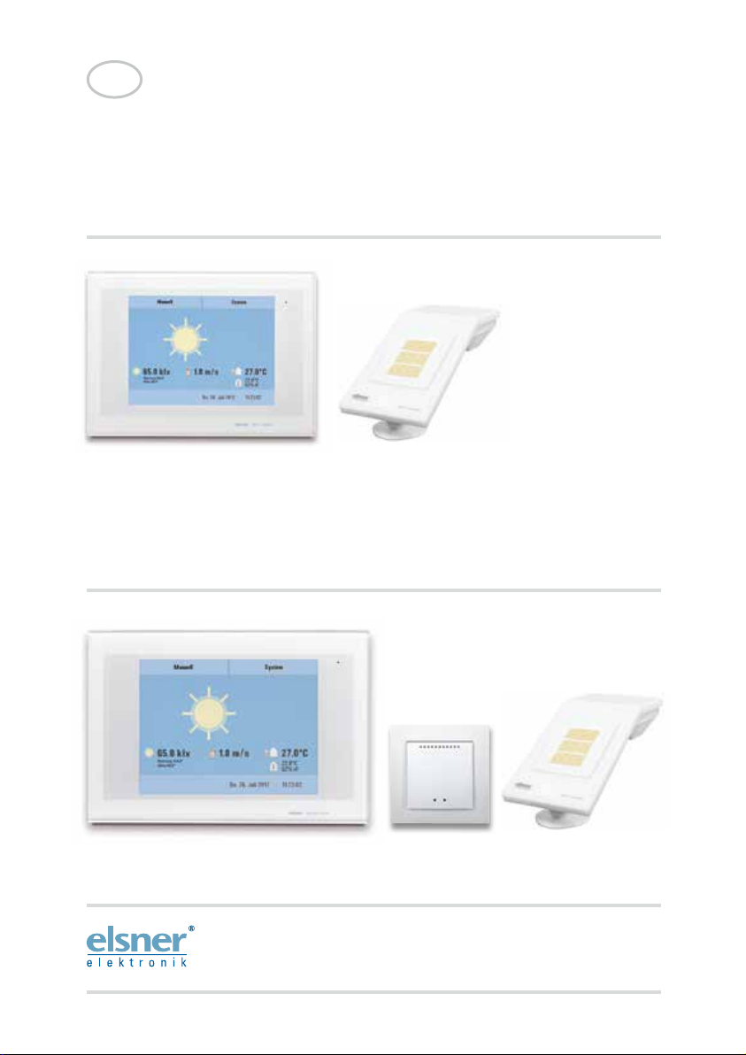
WS1 Style
Control System for Buildings and for Conservatories
WS1 Style 60180-60184 (white), 60185-60189 (black). WS1 Style-4 PF 60194 (white)
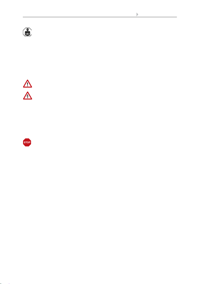
WS1000 Style
Control System for Buildings and for Conservatories
WS1000 Style 60201-60204 (white), 60206-60209 (black). WS1000 Style-10 PF 60214 (white)
including WS1Style-PF and WS1000Style-PF
Installation and Operation
Page 2

Page 3

1 Contents
1. Description ................................................... 7
1.1. Field of application ............................................................................ 8
1.1.1. Delivery scope ........................................................................................................ 8
1.2. Connection and control options ........................................................ 9
1.2.1. Automatic functions in overview ....................................................................... 11
2. Operation and use ....................................... 15
2.1. Weather data display (starting image) ............................................. 16
2.2. The touch display ............................................................................. 18
2.3. Manually operate drives and devices ............................................... 19
2.3.1. The „Manual“ menu ............................................................................................ 19
2.3.2. Internal buttons (group buttons) ........................................................................ 21
2.3.3. Remote control .................................................................................................... 21
2.3.4. Navigation in the System menu ......................................................................... 22
2.3.5. Input keyboard for names and codes ................................................................ 23
2.4. Slideshow ........................................................................................ 23
3. Automatic settings ..................................... 25
3.1. Automatic settings .......................................................................... 26
3.1.1. Safety notice for automatic and alarm functions .............................................. 26
Power failure, maintenance works, etc. (restart of control) .............................. 27
3.1.2. Automatic settings for drive groups and devices ............................................. 27
3.1.3. Drives and devices without automatic functions .............................................. 27
3.1.4. Automatic awning settings ................................................................................. 27
3.1.5. Automatic blind and roller shutter settings ....................................................... 33
3.1.6. Automatic window settings ................................................................................ 41
3.1.7. Automatic ventilation settings ............................................................................ 49
Ventilation modes wireless roof ventilator ........................................................ 55
3.1.8. Automatic heating settings ................................................................................. 56
3.1.9. Automatic air-conditioner settings ..................................................................... 57
3.1.10.Automatic light settings ..................................................................................... 59
3.1.11.Automatic roof gutter heating settings ............................................................. 61
3.1.12.Set up alarm ........................................................................................................ 62
3.1.13.Setting motion detectors .................................................................................... 62
3.2. Adjust general automatic settings ................................................... 63
3.2.1. Adjust twilight value ............................................................................................ 63
3.2.2. Adjust movement delays (shading elements) ................................................... 63
3.2.3. Set timer ............................................................................................................... 64
3.2.4. Adjust ventilation block ....................................................................................... 65
3.2.5. Set night-time re-cooling (ventilation) ............................................................... 65
Elsner Elektronik GmbH • Sohlengrund 16 • 75395 Ostelsheim • Germany
Control System WS1 Style / WS1000 Style • from software version 1.817
Version: 28.05.2018 • Technical changes and errors excepted.
Page 4

2 Contents
3.2.6. Adjust frost alarm ................................................................................................ 66
3.2.7. Set movement limitations (window) .................................................................. 67
3.2.8. Setting a wind delay (shades) ............................................................................ 68
3.2.9. Define automatic reset ........................................................................................ 68
4. Installation .................................................. 71
4.1. Procedure ......................................................................................... 72
4.1.1. Installation notes ................................................................................................. 72
4.1.2. Notes on wireless equipment ............................................................................. 73
4.1.3. Safety notice for automatic and alarm functions .............................................. 73
Power failure, maintenance works, etc. (restart of control) .............................. 74
4.2. Installation of the P04i-GPS Weather Station .................................. 74
4.2.1. Installing the weather station ............................................................................. 74
Installation location .............................................................................................. 74
Device design ........................................................................................................ 76
Preparation for installation .................................................................................. 76
Fitting the lower part with mounting .................................................................. 77
Connection ............................................................................................................ 79
Closing the installation ......................................................................................... 80
4.2.2. Notes on mounting and commissioning ........................................................... 80
4.2.3. Maintenance of the weather station .................................................................. 81
4.3. Installation of a WGTH-UP Indoor Sensor ........................................ 81
4.3.1. Installation of the indoor sensor ........................................................................ 82
Installation location .............................................................................................. 82
Layout .................................................................................................................... 82
Rear view ............................................................................................................... 83
Installation ............................................................................................................. 83
4.3.2. Notes on mounting and commissioning ........................................................... 83
4.3.3. Establish radio connection with WGTH-UP ....................................................... 83
4.4. Installation of the control unit ......................................................... 84
4.4.1. Installation of the control unit WS1000 Style .................................................... 84
Preparing the installation location ...................................................................... 84
Preparing for installation ..................................................................................... 85
Wall-fitting ............................................................................................................. 86
Cavity wall fitting .................................................................................................. 86
Assembling the control unit with concealed box .............................................. 86
Structure of the connector board WS1000 Style ............................................... 88
Structure of the connector board WS1000 Style-PF .......................................... 89
4.4.2. Installation of the control unit WS1 Style .......................................................... 90
Preparing the installation location ...................................................................... 90
Preparing for installation ..................................................................................... 91
Wall-fitting ............................................................................................................. 92
Cavity wall fitting .................................................................................................. 92
Assembling the control unit with concealed box .............................................. 92
Structure of the connector board WS1 Style ..................................................... 94
Elsner Elektronik GmbH • Sohlengrund 16 • 75395 Ostelsheim • Germany
Control System WS1 Style / WS1000 Style • from software version 1.817
Version: 28.05.2018 • Technical changes and errors excepted.
Page 5

3 Contents
Structure of the connector board WS1 Style-PF ................................................ 95
4.4.3. Connect drives and devices ................................................................................ 95
Connect drive groups ........................................................................................... 95
Connect devices to the multifunctional outputs ................................................ 96
Connect devices to the multifunctional inputs ................................................... 96
4.4.4. Connection manual push buttons ...................................................................... 97
Connecting drives and devices wirelessly .......................................................... 97
5. Commissioning ........................................... 99
5.1. Procedure ....................................................................................... 100
5.1.1. Start control unit ................................................................................................ 100
5.1.2. Check sensor functions ..................................................................................... 101
6. Basic Setting ............................................. 103
6.1. The “Installation” menu ................................................................ 104
6.1.1. Set up drives and drive groups ........................................................................ 104
Tips on connecting windows ............................................................................. 108
6.1.2. Assign external buttons .................................................................................... 108
6.1.3. Assign internal buttons (group buttons) ......................................................... 110
6.1.4. Set up multifunctional outputs ......................................................................... 111
6.1.5. Set up multifunctionals inputs ......................................................................... 112
6.1.6. Wireless connections ........................................................................................ 114
Learn wireless connection ................................................................................. 114
Status ................................................................................................................... 115
Delete wireless connection ................................................................................ 120
6.1.7. Indoor sensor for weather display ................................................................... 120
6.1.8. Settings for communication with KNX (WS1000 only) .................................. 120
6.1.9. Configuring internal thermometer/hygrometer of WS1 ................................. 121
6.1.10.Define channel order ........................................................................................ 122
6.2. WS1 / WS1000 Settings ................................................................. 122
6.2.1. Settings ............................................................................................................... 123
Enter time and date manually ........................................................................... 123
Change language ................................................................................................ 123
Adjust screen ...................................................................................................... 124
Switch on/off button tone .................................................................................. 124
Select time zone .................................................................................................. 125
Enter location (only DCF weather stations) ...................................................... 125
Calibrate touch .................................................................................................... 126
Adjust logo lighting ............................................................................................ 126
6.2.2. Service settings .................................................................................................. 127
Reset (new start) ................................................................................................. 127
Factory settings ................................................................................................... 128
Internal area ........................................................................................................ 128
6.2.3. Access code ........................................................................................................ 128
Elsner Elektronik GmbH • Sohlengrund 16 • 75395 Ostelsheim • Germany
Control System WS1 Style / WS1000 Style • from software version 1.817
Version: 28.05.2018 • Technical changes and errors excepted.
Page 6

4 Contents
Using an SD card ................................................................................................ 129
Show images on display .................................................................................... 130
Saving and loading configuration data ............................................................ 131
7. Tables, diagrams, maintenance ................ 133
7.1. Care and maintenance ................................................................... 134
Maintenance of the weather station ................................................................. 134
Maintenance of the control unit ........................................................................ 134
7.2. Technical specifications ................................................................ 134
7.2.1. Technical specifications Control Unit WS1 Style ............................................ 134
7.2.2. Technical specifications Control Unit WS1000 Style ...................................... 135
7.2.3. Technical specifications P04i-GPS ................................................................... 135
7.2.4. Technical specifications WGTH-UP .................................................................. 136
7.2.5. Units for sun and wind ...................................................................................... 137
7.3. Alarm and error messages ............................................................. 138
7.3.1. Weather data display messages ....................................................................... 138
7.3.2. “Manual” menu messages ............................................................................... 139
7.3.3. Diagrams WS1 ................................................................................................... 140
7.3.4. Diagrams WS1000 ............................................................................................. 143
7.3.5. Connection of several drives to one 230 V drive output ................................ 146
7.3.6. Use drive outputs for centralised control ........................................................ 147
Centralised control with IMSG 230 Motor Control Units (230 V drive output) 147
Centralised control with IMSG-UC Motor Control Units ................................. 148
7.4. Personal automatic settings data .................................................. 149
Elsner Elektronik GmbH • Sohlengrund 16 • 75395 Ostelsheim • Germany
Control System WS1 Style / WS1000 Style • from software version 1.817
Version: 28.05.2018 • Technical changes and errors excepted.
Page 7
5 Clarification of signs
Installation, inspection, commissioning and troubleshooting of the device
must only be carried out by a competent electrician.
This manual is amended periodically and will be brought into line with new software
releases. The change status (software version and date) can be found in the contents footer.
If you have a device with a later software version, please check
www.elsner-elektronik.de in the menu area "Service" to find out whether a more up-todate version of the manual is available.
Clarification of signs used in this manual
Safety advice.
Safety advice for working on electrical connections, components,
etc.
DANGER!
WARNING!
CAUTION!
ATTENTION!
“Control unit”
“Manual”
... indicates an immediately hazardous situation which will lead to
death or severe injuries if it is not avoided.
... indicates a potentially hazardous situation which may lead to
death or severe injuries if it is not avoided.
... indicates a potentially hazardous situation which may lead to
trivial or minor injuries if it is not avoided.
... indicates a situation which may lead to damage to property if it is
not avoided.
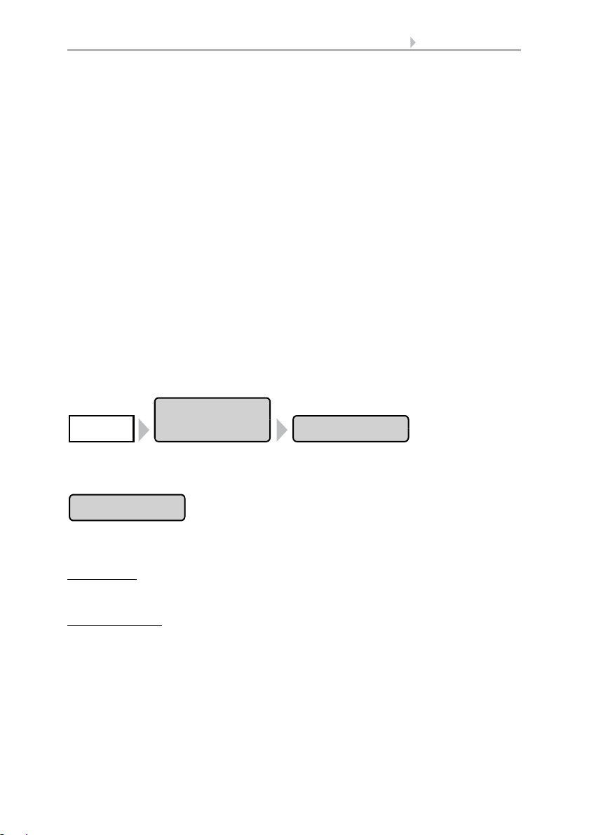
The symbol is followed by a menu path. In this menu the settings
just described can be changed.
The symbol is followed by chapter information with a page number. In this chapter you will find additional information about the
setting just described.
Page 8

6 Clarification of signs
Page 9

7 Description
1. Description
Control System WS1 Style / WS1000 Style • Version: 28.05.2018 • Technical changes and errors excepted.
Page 10

8 Description
1.1. Field of application
The control system was developed so that the different technical equipment installed
in conservatories and buildings could be centrally controlled. The control units offer
the highest measure of flexibility with regard to connections, allowing settings to be
optimally and individually adjusted to the circumstances on site. Please use this operational guide to adjust the automatic functions to your requirements and enable comfortable manual operation.
1.1.1. Delivery scope
• Central control and operations unit
WS1 Style: With integrated indoor sensor. With 1, 2, 3 or 4 drive outputs for
230 V motors or without drive outputs, depending on model.
WS1 Style-PF: With integrated indoor sensor. With 4 potential-free drive
outputs.
WS1000 Style: With 4, 6, 8 or 10 drive outputs for 230 V motors, depending on
model.
WS1000 Style-PF: With 10 potential-free drive outputs.
• Weather station
•Manual
Additionally with WS1000 Color:
• WGTH-UP indoor sensor with frame
(You need a socket ø 60 mm, 42 mm deep additionally)
Control System WS1 Style / WS1000 Style • Version: 28.05.2018 • Technical changes and errors excepted.
Page 11
9 Description
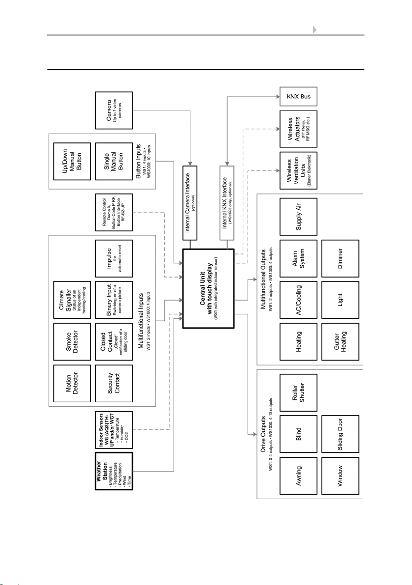
1.2. Connection and control options
Control System WS1 Style / WS1000 Style • Version: 28.05.2018 • Technical changes and errors excepted.
Page 12

10 Description
The following environmental parameters will be measured and displayed:
• Outdoor and indoor temperature
• Air humidity inside
• Lighting (intensity and direction, twilight recognition)
•Wind speed
•Precipitation
•Time/date
The following drives can be connected to the drive outputs:
(WS1 Style: 0-4 drive outputs, WS1000 Style: 4-10 drive outputs)
• Electrically-operated awnings
• Electrically-operated blinds
• Electrically-operated shutters
• Electrically-operated windows and sliding roofs
• Electrically-operated sliding doors
The following devices can be connected to the multifunctional outputs:
(WS1 Style: 2 MF outputs, WS1000 Style: 4 MF outputs)
•Heating
• Cooling
• Alarm equipment
• Lighting
• Roof gutter heating
• Ventilation units
• Dimmer (for a light)
The following can be connected to the multifunctional inputs:
(WS1 Style: 2 MF inputs, WS1000 Style: 4 MF inputs)
• Motion detector
• Smoke detector
• Climate sensor (A climate or heating unit which is independent of the control
unit. Status query “active”/“not active”, for cancelling ventilation)
• Safety contacts to keep drives in secured position
• Closed-contact for closing notification of a sliding door
• Impulse for automatic reset (e.g. button or impulse at alarm activation)
• Binary contact
The following devices can be connected via a wireless connection:
• WGTH-UP indoor sensors for temperature and humidity measurement at
various places in the room. This allows various climate areas to be realised (e.
g. living and plant areas in the conservatory)
• WGT temperature sensor for temperature measurement at various places in
the room and, for example, in the ground for control of the floor heating
• Radio remote control Remo 8/pro, push buttons Corlo P RF, push button
interface RF-B2-UP
• Elsner ventilation devices (WL400, WL800, WL-Z)
Control System WS1 Style / WS1000 Style • Version: 28.05.2018 • Technical changes and errors excepted.
Page 13

11 Description
• Fan module RF-VM for connecting fans/circulating air heating units from other
manufacturers
• RF relay (radio relay, On/Off)
• RF MSG (radio motor control device, Up/Down)
The following additional options are available:
• Connection of up to 10 external Up/Down wall buttons for manual operation of
drives and devices on the spot
• Presentation of a slide show on SD card, data storage on SD card
The following functions are available with WS1000 Style only:
• Communication with the KNX bus system via an optional KNX interface
1.2.1. Automatic functions in overview
Devices connected via the “Dimmer” output (e.g. lighting) have no automatic functions. They can however be operated manually via the display.
Sliding doors also have no automatic functions. They can be fitted with a close-contact (to a multifunctional input) and be manually operated via the display.
Automatic functions for windows/sliding roofs:
• Opening above a selectable indoor temperature (can be switched off)
• Opening above a selectable air humidity level in the room (can be switched off)
• Close when the supply air temperature is higher than the room temperature
(can be switched off)
• Night-time re-cooling (settable running times)
• Daily forced closure (settable running times)
• Outdoor temperature block: Block beneath a selectable outdoor temperature
(can be switched off)
• Keep closed in a period which can be set
• Frost alarm: Close in case of precipitation beneath a selectable outdoor
temperature (can be switched off)
• Wind alarm: Close when a selectable wind speed is exceeded (can be switched
off)
• Rain alarm: Close when there is precipitation or move to a gap (can be switched
off)
• Closing when cooling/air-conditioning unit is active
If a motion detector is connected, windows will be closed automatically when a breakin alarm is triggered. If a smoke detector is connected, windows will be opened automatically when a fire alarm is triggered.
Step windows will be opened step-by-step. An opening position can be set for sliding
windows.
Control System WS1 Style / WS1000 Style • Version: 28.05.2018 • Technical changes and errors excepted.
Page 14

12 Description
Automatic functions for awnings:
• Extend according to brightness and the position of the sun
or retract regardless of brightness (extending only manually)
or extend regardless of brightness (visual protection, automatically retraction
only when there is a rain or wind alarm)
• Adjustable movement position
• Keep retracted until a selectable indoor temperature is reached
(can be switched off)
• Outdoor temperature block: Block beneath a selectable outdoor temperature
(can be switched off)
• Frost alarm: Retract in case of precipitation beneath a selectable outdoor
temperature (can be switched off)
• Wind alarm: Retract when a selectable wind speed is exceeded (can be
switched off)
• Rain alarm: Retract when there is precipitation (can be switched off)
If a smoke detector is connected, awnings will be automatically retracted when a fire
alarm is triggered.
Automatic functions for blinds:
• Closing according to brightness or position of the sun
or keep open regardless of brightness (only time-controlled or manual closing)
or keep closed regardless of brightness (visual protection, automatically retract
only when there is a rain or wind alarm) with light reversal
• Adjustable movement position and slat position (slat tracking of the sun height
possible)
• Leave open until a selectable indoor temperature is reached
(can be switched off)
• Close at night/twilight (can be switched off)
• Close daily (settable running times)
• Outdoor temperature block: Block beneath a selectable outdoor temperature
(can be switched off)
• Frost alarm: Retract in case of precipitation beneath a selectable outdoor
temperature (can be switched off)
• Wind alarm: Retract when a selectable wind speed is exceeded (can be
switched off)
• Rain alarm: Retract when there is precipitation (can be switched off)
If a smoke detector is connected, blinds will be opened automatically when a fire alarm
is triggered.
Automatic functions for shutters:
• Closing according to brightness or position of the sun
or keep open regardless of brightness (only time-controlled or manual closing)
or keep closed regardless of brightness (visual protection, automatic retraction
only when there is a rain or wind alarm)
• Adjustable movement position
Control System WS1 Style / WS1000 Style • Version: 28.05.2018 • Technical changes and errors excepted.
Page 15

13 Description
• Leave open until a selectable indoor temperature is reached
(can be switched off)
• Close at night/twilight Leave open until
• Close daily (settable running times)
• Outdoor temperature block: Block beneath a selectable outdoor temperature
(can be switched off)
• Frost alarm: Retract in case of precipitation beneath a selectable outdoor
temperature (can be switched off)
• Wind alarm: Retract when a selectable wind speed is exceeded (can be
switched off)
• Rain alarm: Retract when there is precipitation (can be switched off)
If a smoke detector is connected, shutters will be opened automatically when a fire
alarm is triggered.
Automatic functions for heatings:
• Switch on daily below a selectable indoor temperature
• Night setback (with adjustment of time and temperature until the setback is
made)
If a smoke detector is connected, the heating will be automatically switched off when
a fire alarm is triggered.
Automatic functions for coolings and air-conditioning units:
• Switch on daily above a selectable indoor temperature
• Night mode (with adjustment of time and temperature until cooling takes
place)
• Cancel ventilation when cooling/air-conditioning unit is active
If a smoke detector is connected, the cooling will be automatically switched off when
a fire alarm is triggered.
Automatic ventilation functions:
• Ventilation above a selectable indoor temperature (can be switched off)
• Ventilation above a selectable air humidity level in the room
(can be switched off)
• Winter operation: supply air will be closed below a selectable outdoor
temperature (can be switched off)
• Summer operation: supply air will be shut off if outdoor temperature is higher
than room temperature
• Adjustable minimum and maximum speeds for motorised fans
• Night-time re-cooling (settable running times)
• Daily forced ventilation (settable running times)
• Additionally with roof ventilators WL400/800: recirculating air for heat
recovery; recirculating air to avoid condensation
• Cancel ventilation when cooling/air-conditioning unit is active
Control System WS1 Style / WS1000 Style • Version: 28.05.2018 • Technical changes and errors excepted.
Page 16

14 Description
If a smoke detector is connected, ventilation will be activated automatically when there
is a fire alarm.
Automatic functions for light:
• Switch on daily (settable running times, with and without twilight recognition)
• Switch on at twilight
• Switch on when an alarm triggers (motion/smoke detector)
Automatic functions for roof gutter heatings:
• Switch on within an adjustable temperature range
Automatic alarm settings:
• Motion detector: The period of alarm readiness is adjustable. If the alarm is
triggered within this period, all windows close. After 5 minutes without a new
alarm signal, normal automatic operation will be resumed.
• Smoke detector: When the alarm triggers, shades retract (escape routes),
windows open, ventilators open/switch on (getting rid of smoke) and heatings
and air conditioners switch off. No manual operation is possible. An acoustic
warning signal will sound at the control system.
Control System WS1 Style / WS1000 Style • Version: 28.05.2018 • Technical changes and errors excepted.
Page 17

15 Operation and use
2. Operation and use
Control System WS1 Style / WS1000 Style • Version: 28.05.2018 • Technical changes and errors excepted.
Page 18
16 Operation and use
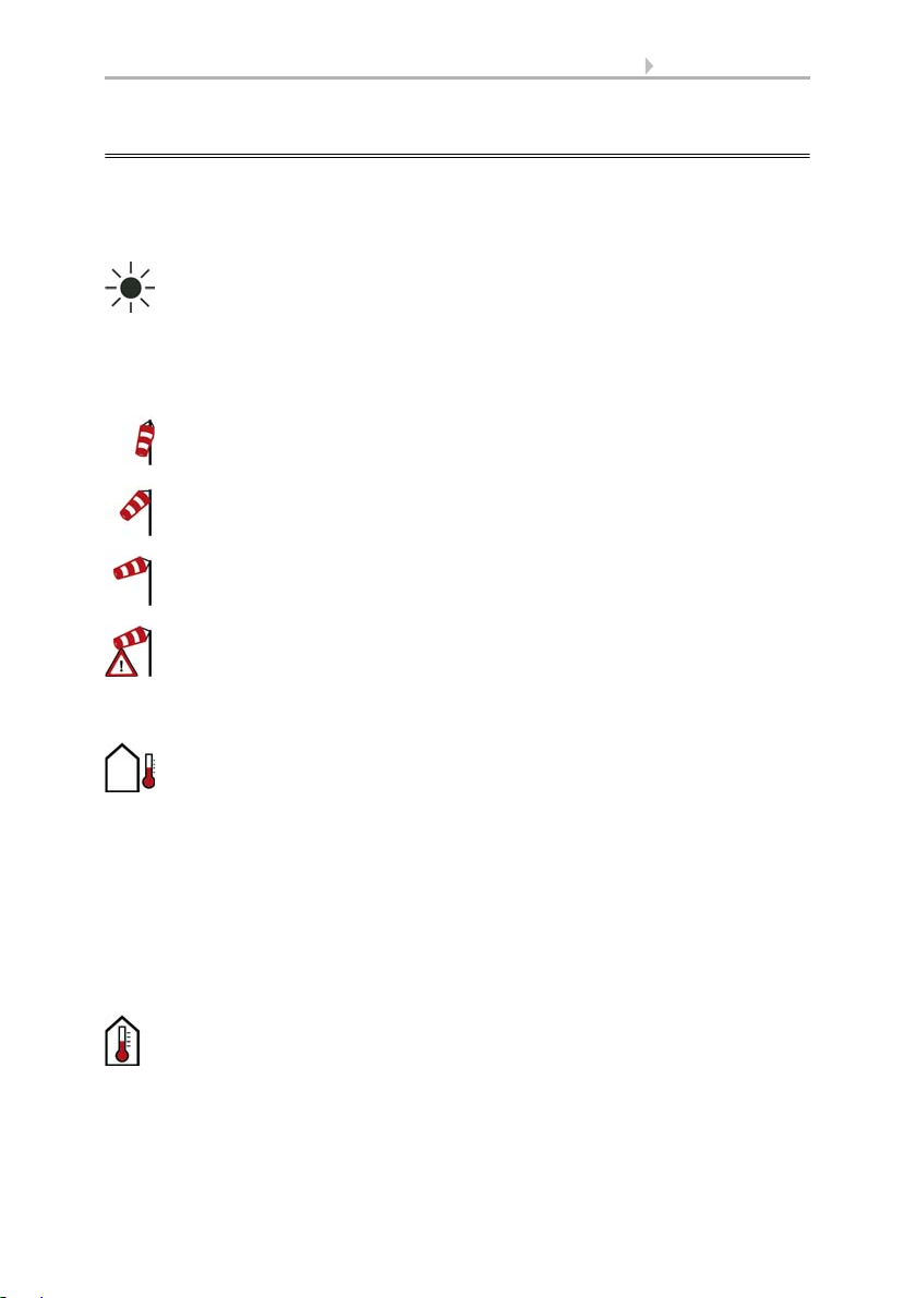
Intensity: Light intensity (brightness) in Lux (lx) or Kilolux (klx)
Direction: Direction (azimuth) in degrees
Height: Elevation over the horizon in degrees
Calm: up to 1.9 m/s
Slight wind: 2.0 to 9.9 m/s
Strong wind: 10.0 m/s and up
A caution flag appears besides the wind symbol if wind alarm has been
triggered for a drive.
Outdoor temperature at the weather station in degrees Celsius (°C)
Temperature in degrees Celsius (°C)
Air humidity in %RH
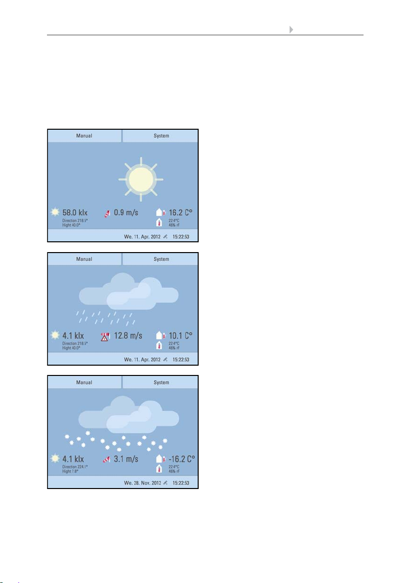
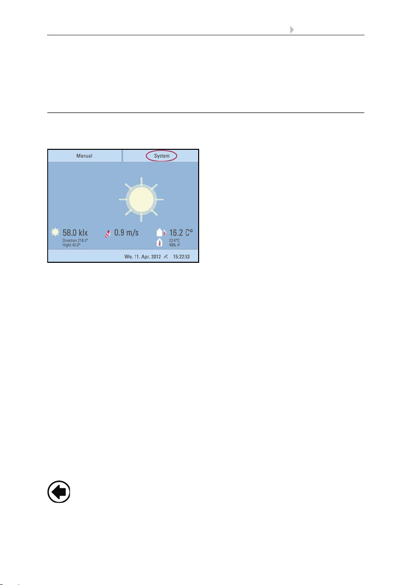
2.1. Weather data display (starting image)
As a starting image, the control system shows the current weather data:
Sun data
Wind
The wind speed will be shown in metres per second (m/s) and the windsock changes:
Outdoor temperature
Night-time Re-cooling, Frost Alarm and Window Movement Limitation are dis-
played in turn next to the outdoor temperature value as long as the relevant function
is active.
3.3. Set night_time re-cooling (ventilation)
3.3. Adjust frost alarm
3.3. Set movement limitations (windows)
Indoor information
Control System WS1 Style / WS1000 Style • Version: 28.05.2018 • Technical changes and errors excepted.
Page 19
17 Operation and use
Sunny or cloudy:
The sun moves across the sky according to
its current direction and height.
Rain:
When there is a precipitation report and
temperatures above -3 °C, it is raining.
Snow:
When there is a precipitation report and
temperatures below -3 °C, it is snowing.
You may select which indoor information is displayed (e. g. if several sensors are connected).
System > Installation > Weather Display
6.1. Indoor sensor for weather display
The general weather situation is shown graphically:
Control System WS1 Style / WS1000 Style • Version: 28.05.2018 • Technical changes and errors excepted.
Page 20
18 Operation and use
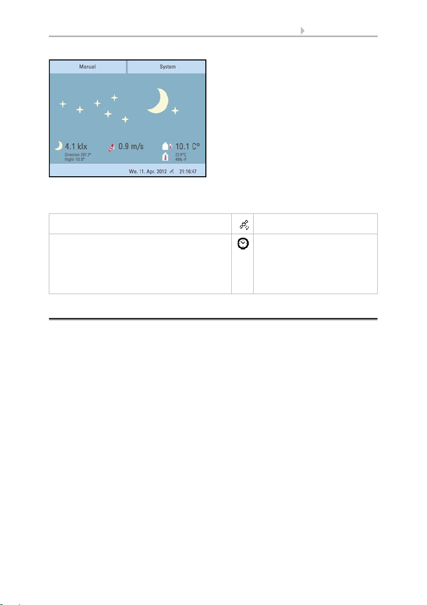
Night:
At night (twilight) the display will be darker; instead of the sun, the moon and stars
will appear.
The date and time will be shown on the lower right on the display. The following symbols are displayed, depending on which source the time signal is from:
GPS reception (from weather station) Satellite
Reception of time via KNX bus
(WS1000 Color)
Position must be entered manually for shading
control:
System > WS1000 Settings > Settings > Position
6.2.1.Enter position
Clock
2.2. The touch display
Manual control, as well as setting the defaults for the automatic functions and the connected equipment, is via the control’s stationary touch display. The button surfaces are
operated in this area by touching the display. When a button is activated, there is visual
feedback and a brief audio signal sounds. The sound can be switched off.
System > WS1 / WS1000 Settings > Settings > Button tone
6.2.1. Settings > Button tone
If the push buttons shown do not match up with the touch-sensitive surfaces (you have
to press “next to the button”), the touch display can be calibrated as follows.
System > WS1 / WS1000 Settings > Settings > Calibrate touch
6.2.1. Calibrate touch
Operating the display with long fingernails will not damage the screen or the touch
function. Touching the display with very hard or pointed objects (e.g. those made from
glass, gems or metal) should be avoided as this can cause marks.
Control System WS1 Style / WS1000 Style • Version: 28.05.2018 • Technical changes and errors excepted.
Page 21
19 Operation and use
Use the arrow keys to scroll through the list.
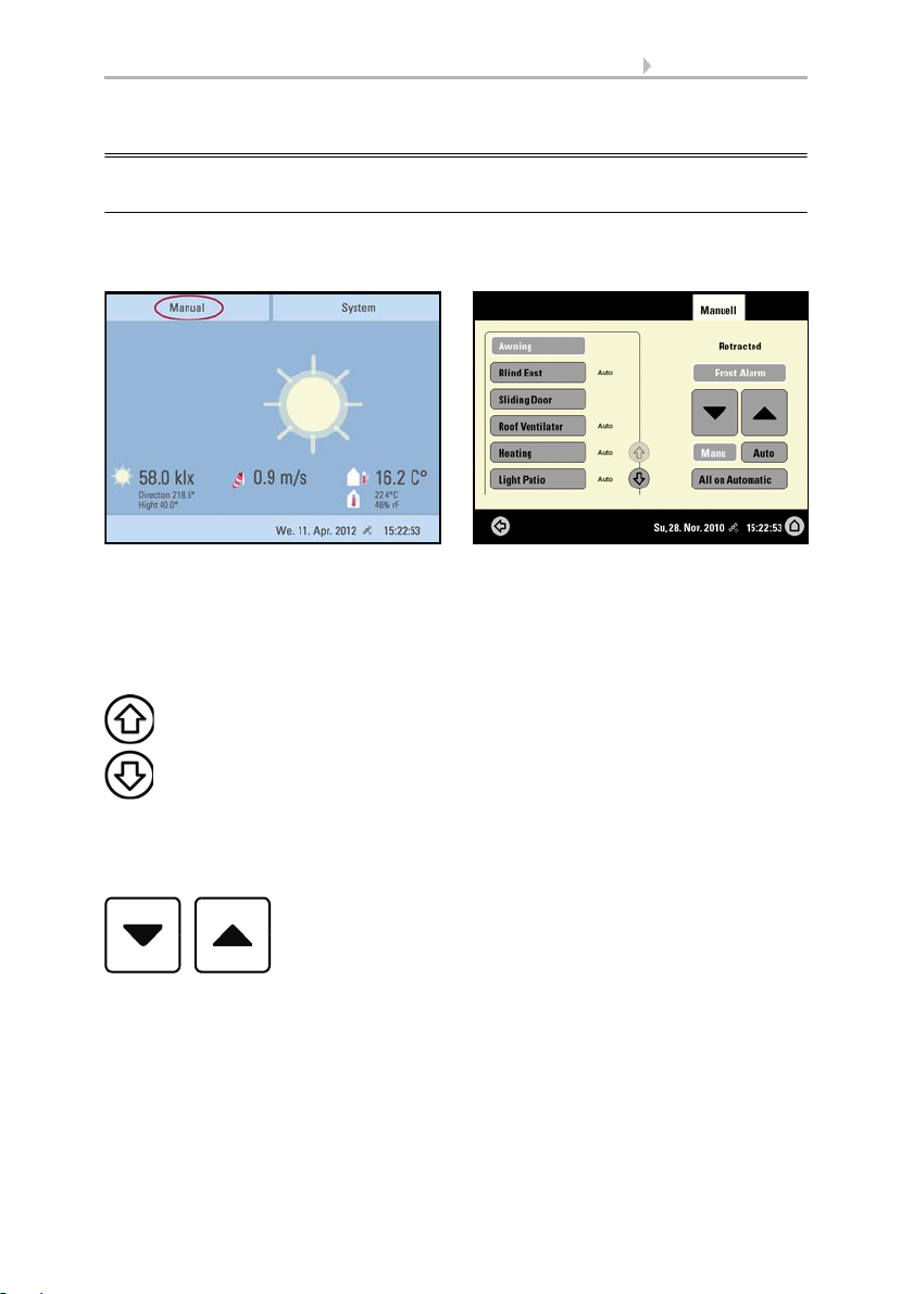
2.3. Manually operate drives and devices
2.3.1. The „Manual“ menu
You can reach the menu for manual control of drives and equipment by using the button Manual:
Here you can operate all connected drives and devices directly: Use the buttons to select the name of the drive or device you want to operate. You can change the order of
the list in the System menu.
System > Installation > Channel Order
6.1. Define channel order
The selected device is marked in white. On the right-hand side you will receive status
information (e.g. on/off, open/closed, exhaust air level, error messages) and various
control options (up/down arrow keys or on/off buttons).
The Down and Up buttons are fitted with automatic time functions.
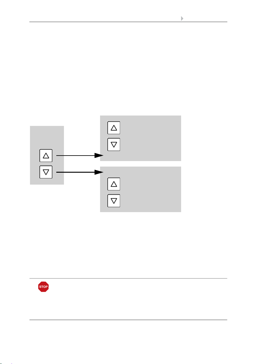
Drives:
The drive can be precisely positioned with brief button presses (less than 1 second,
short audio signal). For shutters and roller blinds, only a short step-movement command is triggered. If the button is pressed for longer than 1 second (higher audio signal: locking signal), the drive moves independently to the end position. A brief press in
the opposite direction stops the drive.
Control System WS1 Style / WS1000 Style • Version: 28.05.2018 • Technical changes and errors excepted.
Page 22
20 Operation and use
Fan OFF
(stopped,
flap closed)
Recirculation Mode
press
Speed higher
Speed lower
(until OFF)
press
Extraction Mode
Speed lower
(until OFF)
Speed higher
For shades and windows, the movement position is shown in percent above the Up-/
Down buttons (for blinds, also the slat position). For radio motor control units, the position shown can deviate from the movement position set in the automatic mode by up
to 2%.
Ventilation units WL400 and WL800:
Ventilation units WL400 and WL800 are operated in 10% steps by briefly pressing the
button (less than 1 second, brief sound, 10 ventilation levels). By pressing the button
longer, the fan speed is changed continuously. Release the button to stop speed
change.
Note: In rare cases, radio disturbances can lead to continuing speed change after having released the button. Please briefly press the other direction then.
Block because of rain, wind or frost alarm:
If a drive group is momentarily blocked for manual operation by a rain, wind or frost
alarm, the arrow keys will be greyed out and may not be used. The message “Rain
alarm” and/or “Wind alarm” is shown.
The frost alarm can be deactivated by pressing the corresponding button (see diagram); manual operation is then possible again. The frost block will then be first active
for this drive again when it is reactivated manually or the next time the frost alarm is
triggered.
ATTENTION
Material damage due to movement of frozen shading elements!
The drive and hangings may be damaged if a firmly frozen outdoor
shading is moved!
•Make shure the rails are no longer frozen before manually switching
off the frost alarm.
Control System WS1 Style / WS1000 Style • Version: 28.05.2018 • Technical changes and errors excepted.
Page 23
21 Operation and use
Manu Auto
Automatic Reset
Back to the weather data display (starting image)
Whether a drive or device is in automatic mode or manually operated can be recognised from the white marking on the buttons on the right and the text “Auto” next to
the name button in the list on the left. By pressing the button you can switch from one
to another.
After being operated manually the drive or device remains in manual mode. The automatic functions are thus switched off and only the rain and wind protection will be carried out. The equipment will only switch back into automatic mode when reset by hand
(“Manu” button) or through the daily automatic reset. In the Automatic menu, the automatic reset can be activated separately for each drive group and each device.
This button allows you to perform the automatic reset manually. All systems for which
an automatic reset has been set are then set to automatic mode.
External buttons
As well as operating the controls via the display, it is possible to connect external buttons (wall buttons) to the control unit. In the System menu the individual buttons can
be assigned to any drives or devices.
System > Installation > Ext. Buttons
6.1. Assign external buttons
2.3.2. Internal buttons (group buttons)
It is possible to operate several drives or devices at the same time via a collective group
button (internal software button). This makes it possible to close all windows with a
single button press, for example. These group buttons can be set up in the System
menu.
System > Installation > Int. Buttons
6.1. Assign internal buttons (group buttons)
2.3.3. Remote control
Drives and equipment can be controlled by using the remote controller Remo 8 (pro),
which can be ordered among the accessories. The hand-held transmitter must be configured in the control as a participant to the radio network. Then follows the allocation
Control System WS1 Style / WS1000 Style • Version: 28.05.2018 • Technical changes and errors excepted.
Page 24
22 Operation and use
Back to the previous menu level (only settings already saved with OK will
be applied)
of drives and equipment to the eight remote control channels. In the control, several
Remo 8 (pro) devices can be configured.
6.1. Wireless connections
2.3.4. Navigation in the System menu
All settings for drives and devices, for the automation and the control system are
changed in the System menu, which you reach via the System button:
In three sub-menus you can carry out the following adjustments:
Installation:
• Specify fundamental characteristics of the drives at inputs/outputs
• Set up wireless connections to devices
• Define the order in which the drives and devices are shown (e.g. in the manual
menu)
Automatic settings:
• Define automatic functions for the individual drives and devices
• Adjust general automatic settings: Twilight value, movement delays, forced
closure, ventilation block and automatic reset
Control Settings:
• Change personal data such as Time/Date and location and adjust the screen
display to your personal preferences
• Restart the control unit, reset to factory defaults and change internal settings
• Set an access code to protect the “Installation” and “Automatic Settings”
menus from unauthorised changes.
The following buttons are needed constantly for navigation in the System menu:
Control System WS1 Style / WS1000 Style • Version: 28.05.2018 • Technical changes and errors excepted.
Page 25
23 Operation and use
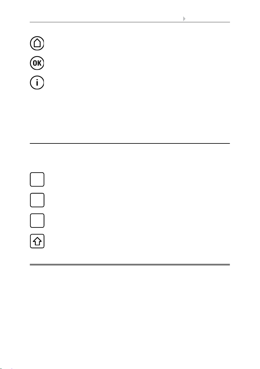
Back to the weather data display (starting image)
Confirms (saves) adjustments made
Info button: Appears in many menus next to the option settings. Press the
button for an explanation of the function shown in the upper display area.
Press again for the explanation to disappear.
Selects the input keyboard for letters and numbers.
ABC
Selects the input keyboard for symbols and umlauts.
&
Delete. Removes the preceding character.
Shift key. Switches between upper and lower case letters.
On the top right, beneath the System field, is shown which menu you are currently in
as well as the path by which you arrived there. For example, if you are in the Automation menu for the light intensity of the “South awning”, the path will be:
System > Automation > Awning > Awning South > Intensity
2.3.5. Input keyboard for names and codes
In some menus an input keyboard for names and codes appears. The words can be
typed in completely normally.
Special keys:
2.4. Slideshow
The WS1 Style / WS1000 Style can play back digitally-stored image data as a slideshow. For this, the image data must be saved onto an SD card and fulfil the following
requirements:
• Data format Bitmap (BMP)
• Size 640 x 480 pixels
• Color intensity 24 bit or 16 bit
•No compression (RLE)
• The data must be saved in the uppermost level of the card's directory (root
directory)
Control System WS1 Style / WS1000 Style • Version: 28.05.2018 • Technical changes and errors excepted.
Page 26
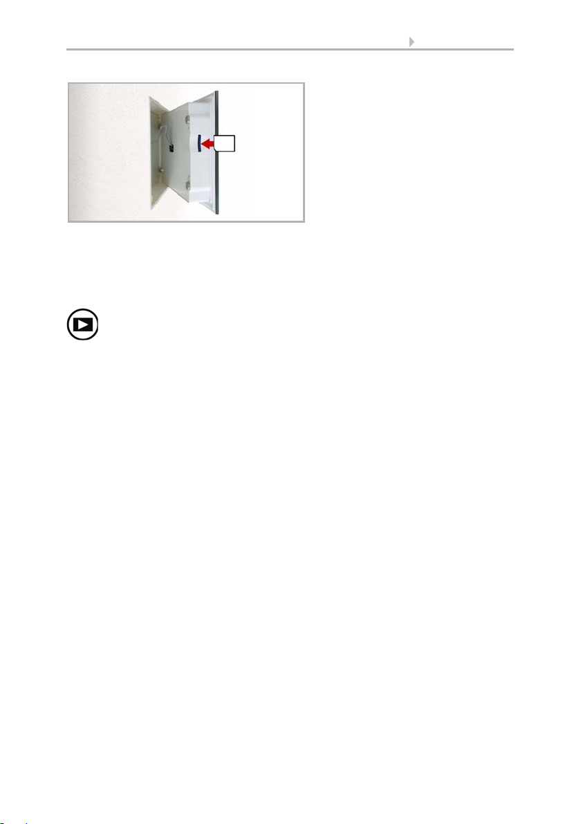
24 Operation and use
The SD card slot can be found on the
inner face of the housing.
The display is held on the wall by
magnets. It is connected to the power
electronics in the concealed box with
a cable. Lift the display unit to the
front without breaking the cable connection.
Wall
Press „play-back“ to start the slideshow.
The SD card is pushed into the slot, until it clicks into place.
The card will automatically be recognised. If image data are stored on the card, the
symbol for „play-back“ appears at the bottom right-hand side of the weather data display.
The image changes approx. every 45 seconds (for images with 24-bit color intensity).
To return to the weather data display, touch the screen or remove the SD card (briefly
press down on the card so that it pops out).
Further information about the image display can be found in chapter
6.2. Using an SD card
Control System WS1 Style / WS1000 Style • Version: 28.05.2018 • Technical changes and errors excepted.
Page 27

25 Automatic settings
3. Automatic settings
Control System WS1 Style / WS1000 Style • Version: 28.05.2018 • Technical changes and errors excepted.
Page 28
26 Automatic settings
3.1. Automatic settings
In the menu System > Automatic Settings you can make the following adjustments:
• Define automatic functions for the individual drives and devices
• Adjust general automatic settings: Twilight value, movement delays, timer,
ventilation block, night time re-cooling, frost alarm and automatic reset
In order to set the automatic functions, the basic settings must already have been
made.
6. Basic setting
Please adjust the settings for drives and devices to your individual circumstances. Only
in this way can alarm and blocking functions like rain or wind warnings help to protect
external awnings or prevent rain from coming in through the window.
3.1.1. Safety notice for automatic and alarm
functions
WARNING!
Risk of injury due to automatically moved components!
The automatic control may cause parts of the system to travel
and pose a danger to humans.
• No persons may remain in the travelling range of parts
driven by an electric motor.
• Adhere to the relevant building regulations (see guideline for
power-operated windows, doors and gates BGR 232 et al).
• Always disconnect the system from the mains power before
maintenance or cleaning (e.g. switch off/remove fuse).
Precipitation warning for automatically controlled windows:
Some time can pass before falling rain is recognised by the sensors in the system, depending on the rain amount and outdoor temperature. Furthermore, a closure time
must be calculated for electrically-actuated windows or sliding roofs. Humiditysensitive items should therefore not be placed in an area where they might be damaged by
incoming precipitation. Please also bear in mind that in the event of a power failure and
rainfall, a window will not be automatically closed if no emergency generator is installed.
Running rails of shades icing up:
Note that the rails of shutters, awnings and blind which are externally mounted can ice
up. Operating the drive under such conditions can damage the shades and drives.
Control System WS1 Style / WS1000 Style • Version: 28.05.2018 • Technical changes and errors excepted.
Page 29

27 Automatic settings
Power failure, maintenance works, etc. (restart of control)
If a power outage occurs, the control unit can no longer control the connected drives!
If the functional scope must be guaranteed even during a power cut, an emergency
power unit with a corresponding switch from network power to emergency operation
should be installed by the customer.
Settings saved in the control unit programme will be maintained even during a power
outage.
Note: After every re-start (e. g. return of voltage after mains failure or manual reset)
all drives and devices with active automatic reset are in automatic mode.
If cleaning or maintenance work is to be carried out in the conservatory/building, the
control unit should be de-energised and secure against restart by disconnection of the
customer-installed fuse. This ensures that the connected drives cannot start.
3.1.2. Automatic settings for drive groups and
devices
3.1.3. Drives and devices without automatic
functions
Devices connected via the “Dimmer” output (e.g. lighting) have no automatic functions. They can however be operated manually via the display.
Sliding doors also have no automatic functions. They can also be operated manually
via the display. In addition, sliding doors can be fitted with a close-contact (connection
to a multifunctional input). In this way the control unit knows whether the door is open
or closed.
3.1.4. Automatic awning settings
For connected awnings or awning groups the following automatic settings can be
changed:
• Light intensity
• Direction of sun
• Height of sun
• Movement position
• Indoor sensor to be used for the awning
• Indoor temperature block
• Outdoor temperature block
• Frost alarm
• Wind alarm
• Rain alarm
• Enable/Disable automatic reset
Control System WS1 Style / WS1000 Style • Version: 28.05.2018 • Technical changes and errors excepted.
Page 30
28 Automatic settings
Automatic
Settings
AwningSystem
Intensity
Alarm functions
Alarm functions are used for awnings in manual and in automatic mode.
Fire alarm of a smoke detector has highest priority. All awnings are retracted and cannot be influenced either by automatic or manual.
During frost, wind or rain alarm the awnings are retracted and cannot be manually
extended.
Shade settings
The settings are only executed if an awning is in automatic mode and none of the alarm
functions named above is active.
Highest priority is assigned to the outdoor temperature-block, followed by the in-
door temperature-block (retract).
Only when the direction and height of the sun agree and there is no active block is the
automatic shading by light intensity engaged.
Setting of the automatic
The automatic awning functions can be accessed by pressing the buttons:
Now you can select individual awnings and adjust their settings. For each awning the
following settings can be changed:
Press the button to set the brightness above which the awning will be deployed to offer
shade.
Adjust value:
Default setting: 40 kLux.
7.2. Units for sun and wind
Remain retracted:
awning will then remain retracted unless it is manually operated.
Confirm your setting with the OK button.
For the automatic system to react, the set light intensity value must be exceeded or undercut for the duration of the delay times. This prevents constant extensions and re-
Control System WS1 Style / WS1000 Style • Version: 28.05.2018 • Technical changes and errors excepted.
Use the arrow buttons to change the value as you wish.
If the awning should not react to the brightness, select Never. The
Page 31

29 Automatic settings
Direction of sun
Height of sun
Movem. Position
traction of the awning during rapid-changing light conditions. The movement delays
can be adjusted.
System > Automatic Settings > General Settings > Movement Delays
3.3. Adjust movement delays (shading elements)
Press the button to set the range (sun direction) in which the sun shall be, so that the
awning provides shade.
All directions:
If the sun’s orientation is not decisive for shading purposes, select All
sides (default setting).
Direction:
If the shade should only be deployed when the sun is in a specific orientation, select as appropriate: West, South-West, South, South-East or East. The thick-
ened part of the circle in the centre shows the selected area.
Enter angle:
To set the range in which shading shall be provided in exact numbers,
press the “from 0°” or “to 360°” and adjust the numeric values with the arrows keys
that appear.
Confirm your setting with the OK button.
For as long as no time signal has been received and the time has not been entered
manually (the display on the control unit will show "Please set clock!"), the shades will
only be controlled based on light intensity, temperature and alarm reports. The position of the sun will not be taken into account.
Press the button to set the range (sun height) in which the sun shall be, so that the awning provides shade.
Any angle:
height (default setting).
Enter angle:
“smaller 90°” or “larger 0°” with the adjacent arrow keys. The thickened part of the
graphic shows you the selected area.
Confirm your setting with the OK button.
For as long as no time signal has been received and the time has not been entered
manually (the display on the control unit will show "Please set clock!"), the shades will
only be controlled based on light intensity, temperature and alarm reports. The position of the sun will not be taken into account.
Press the button to set the movement position for the automatic mode. With the arrow
keys, specify the movement position in % (0% = fully retracted, 100% = fully extended).
Default setting: 75%.
If the height of the sun is not decisive for shading purposes, select Any
To exactly specify the hight numerically, change the number values
Control System WS1 Style / WS1000 Style • Version: 28.05.2018 • Technical changes and errors excepted.
Page 32

30 Automatic settings
Sensor Selection
Indoor Temp.
Outdoor Temp.
Confirm your setting with the OK button.
Press the button to select the indoor sensor the control system will use for this awning
(Pre-setting: Internal sensor at WS1, first sensor in the list at WS1000). As long as “No
Sensor” is selected, the indoor temperature will not be taken into account by the control system for this shade.
Confirm your setting with the OK button.
Press the button to set the indoor temperature block. Until an indoor sensor is selected,
the indoor temperature block will not be active.
The interior blocking temperature enables the use of solar energy to warm the room.
When the indoor temperature is below the set value, e.g. in the morning, the shading
will remain retracted despite the sunshine.
As soon as the set indoor temperature is exceeded, the block is released and the shade
is activated.
When the indoor temperature drops once again, the block is reactivated when the temperature drops below the pre-set value by more than 3.0°C (hysteresis). Note that the
shade only retracts once the retraction delay time has elapsed.
System > Automatic Settings > General Settings > Movement Delays
3.3. Adjust movement delays (shading)
Set temperature:
With the arrow keys, adjust the value for the desired room temperature. Default setting: 25.0 °C.
Disable block:
If the awning should be deployed to offer shade regardless of the indoor
temperature, press the Off button.
Confirm your setting with the OK button.
Press the button to set the outdoor temperature block. The block only applies to automatic operation; no shading occurs based on light intensity or the position of the sun.
Even when an outdoor blocking temperature is active, the drive will respond to wind
and rain alarms, as well as manual movement commands.
Please note that the shade rails or other mechanical components can remain iced even
when the outdoor temperature has already risen to a relatively high value.
Control System WS1 Style / WS1000 Style • Version: 28.05.2018 • Technical changes and errors excepted.
Page 33

31 Automatic settings
Behavior
Frost Alarm
ATTENTION
Damage to property by moving frozen shades!
The drive and curtain can be damaged if a frozen outdoor shading
system is used.
•Use the frost alarm function to provide reliable protection against
damage caused by icing.
Set temperature:
If the awning should be blocked when the outdoor temperature is
low, set the value recommended by the manufacturer using the arrow keys. Default
setting: 5.0 °C. The block is countermanded again when the temperature rises more
than 2.0°C over the pre-set value (hysteresis).
Set the shade behavior in the next menu item.
Disable block:
If the awning should be deployed to offer shade regardless of the out-
door temperature (for example with internal awnings), press the Off button.
Confirm your setting with the OK button.
Set the way in which the shade should behave when the outdoor temperature block is
triggered. The button is only active once an outdoor temperature has been set.
Retract:
If the shade should retract when the outdoor temperature falls below the set
value, select Yes (default setting). The shade is only retracted once the movement delay time has elapsed.
Remain in current position:
If the shade should not move when the outdoor temperature falls below the set value, select No. When the rain or wind alarm is triggered, the
shade will be retracted nonetheless (the alarm has priority over blocking temperature).
Confirm your setting with the OK button.
Press the button to active or deactivate the frost alarm for this shade. The frost alarm
retracts the sun shade if the outdoor temperature is low and it is raining/snowing at the
same time. This protects external shades from icing and from damage through movement when the rails are iced up.
The conditions for the triggering of the frost alarm (outdoor temperature, period) are
defined in the menu „General Settings“.
System > Automatic Settings > General Settings > Frost Alarm
Adjust frost alarm, page 62
When the frost alarm is triggered, manual operation of the shade is initially blocked.
You can remove the block manually however. To do this select the appropriate shade
in the Manual menu and press the frost alarm button. If the button is shown normally
(black writing), the block has been removed. The block will then be first active for this
Control System WS1 Style / WS1000 Style • Version: 28.05.2018 • Technical changes and errors excepted.
Page 34
32 Automatic settings
Wind Alarm
Rain Alarm
drive again if it is reactivated maually or the next time the frost alarm is triggered.
Please note that the shade rails or other mechanical components can remain iced even
when the outdoor temperature has already risen to a relatively high value.
ATTENTION
Damage to property by moving frozen shades!
The drive and curtain can be damaged if a frozen outdoor shading
system is used.
•For sensitive curtains, set the frost alarm range generously.
•Before manually switching off the frost alarm, make sure that the
rails are not iced up.
Activate:
Deactivate:
If the sun shade is to be retracted when there is a frost alarm, select Yes.
If the sun shade should offer shade regardless of the frost risk (e.g. for in-
ternal awnings), select No (default setting).
Confirm your setting with the OK button.
Press the button to set the wind alarm. The wind alarm protects the sensitive awning
cloth from damage by retracting the awning.
Adjust values:
Use the arrow keys to adjust the value for wind speed and the length of
time by which it must have been exceeded.
Disable:
If the awning should not react to the wind (e.g. internal awnings), select Never
retract (default setting).
Confirm your setting with the OK button.
A wind alarm triggered for the drive will remain active for 5 minutes. Additionally, a
wind delay can be set for shades. Then the automatic functions remain switched off for
the defined period of time after the end of the wind alarm. Manual operation is however possible again.
System > Automatic Settings > General Settings > Wind Delay
3.3. Setting a wind delay (shades)
Press the button to enable or disable the rain alarm. The rain alarm protects the sensitive awning cloth from damage by retracting the awning.
Enable:
For moisture-sensitive external awnings, select Yes (awning should be retracted when it rains).
Disable:
For internal awnings, select No (awning should not be retracted when it rains,
default setting).
Confirm your setting with the OK button.
Control System WS1 Style / WS1000 Style • Version: 28.05.2018 • Technical changes and errors excepted.
Page 35

33 Automatic settings
Automatik Reset
Press the button to enable or disable the switchover to automatic mode at a set point
in time, or following a manual intervention.
The general Automatic Reset occurs daily at the same time.
Switching on:
the default setting).
Switching off:
Alternatively, the automatic function can be reactivated at a set time following a manual intervention.
Switching on:
Switching off
setting).
Confirm your setting with the OK button.
Automatic Reset time and/or period can be set.
System > Automatic Settings > General Settings > Automatic Reset
3.3. Define automatic reset
To set the awning to Automatic at a set point in time, select Yes (this is
To switch off the awning’s Reset function, select No.
To perform an Automatic Reset after a manual intervention, select Yes.
: To switch off the awning’s Reset function, select No (this is the default
3.1.5. Automatic blind and roller shutter settings
For connected blinds and roller shutters (or groups of blinds/roller shutters) the following automatic settings can be changed:
• Light intensity
• Direction of sun
• Height of sun
• Movement position
• Slat position (only for blinds)
• Indoor sensor to be used for the blind/roller shutter
• Indoor temperature block
• Night closure
• Timed closure
• Outdoor temperature block
• Frost alarm
• Wind alarm
• Rain alarm
• Enable/Disable automatic reset
Alarm Functions
Alarm functions are used for shades in manual and in automatic mode.
Fire alarm of a smoke detector has highest priority. All shades are retracted and cannot be influenced either by automatic or manual operation.
Control System WS1 Style / WS1000 Style • Version: 28.05.2018 • Technical changes and errors excepted.
Page 36

34 Automatic settings
Automatic
settings
BlindSystem
Automatic
settings
ShutterSystem
Intensity
During frost, wind or rain alarm the shades are retracted and cannot be manually
extended.
Shade settings
The settings are only executed if a shade is in automatic mode and none of the aforementioned alarm functions is active.
The highest priority is given to the outdoor temperature block, followed by timed
closure (extend), night closure (extend) and indoor temperature-block (retract).
Only when the direction and height of the sun agree and there is no active block is the
automatic shading by light intensity engaged.
Setting of the automatic
The automatic blind functions can be accessed by pressing the buttons:
The automatic roller shutter functions can be accessed by pressing the buttons:
Now you can select individual blinds respectively roller shutters and adjust their settings. For each shade the following settings can be changed:
Press the button to set the brightness above which the blind respectively the roller
shutter will be deployed to offer shade.
Adjust value:
fault setting: 40 kLux.
7.2. Units for sun and wind
Keep closed:
there is brightness, select Always. The shading will then remain closed and will only
be retracted when the rain or wind alarms trigger, if these functions have been activated. The slat (for blinds) and movement position can be adjusted individually. Manual
opening is possible.
Leave open:
ness, select Never. The shading will then only be closed in the night closing and time
closing periods set by you. Manual closing is possible.
Confirm your setting with the OK button.
Control System WS1 Style / WS1000 Style • Version: 28.05.2018 • Technical changes and errors excepted.
Use the arrow buttons to change the value according to your desire. De-
If the blind respectively the roller shutter should remain closed when
If the blind respectively the roller shutter should not react to the bright-
Page 37

35 Automatic settings
Direction of sun
Height of sun
For the automatic system to react, the set light intensity value must be exceeded or undercut for the duration of the delay times. This prevents constant up and down movement of the shading during rapidly changing light conditions. The movement delays
can be adjusted.
System > Automatic Settings > General Settings > Movement delays
3.3. Adjust movement delays (shading elements)
Press the button to set the range (sun direction) in which the sun shall be, so that the
blind/roller shutter provides shade.
All directions:
If the sun’s orientation is not decisive for shading purposes, select All
sides (default setting).
Direction:
If the shade should only be deployed when the sun is in a specific orientation, select as appropriate: West, South-West, South, South-East or East. The
thickened part of the circle in the centre shows the selected area.
Enter angle:
To set the range in which shading shall be provided in exact numbers,
press the “from 0°” or “to 360°” and adjust the numeric values with the arrows keys
that appear.
Confirm your setting with the OK button.
For as long as no time signal has been received and the time has not been entered
manually (the display on the control unit will show "Please set clock!"), the shades will
only be controlled based on light intensity, temperature and alarm reports. The position of the sun will not be taken into account.
Press the button to set the range (sun height) in which the sun shall be, so that the
blind/roller shutter provides shade.
Any angle:
height (default setting).
Enter angle:
“smaller 90°” or “larger 0°” with the adjacent arrow keys. The thickened part of the
graphic shows you the selected area.
Confirm your setting with the OK button.
For as long as no time signal has been received and the time has not been entered
manually (the display on the control unit will show "Please set clock!"), the shades will
only be controlled based on light intensity, temperature and alarm reports. The position of the sun will not be taken into account.
If the height of the sun is not decisive for shading purposes, select Any
To exactly specify the height numerically, change the number values
Control System WS1 Style / WS1000 Style • Version: 28.05.2018 • Technical changes and errors excepted.
Page 38

36 Automatic settings
Movem. Position
Slat position
Only for blinds!
Sensor Selection
Indoor Temp.
Press the button to set the movement position for the automatic shading. With the arrow keys, specify the movement position in % (0% = fully retracted, 100% = fully extended). Default setting: 75%.
Confirm your setting with the OK button.
Press the button to set the angular position of the slats.
Fixed angle:
position, leave the button position at No (do not follow the sun's height). With the arrow keys, specify the slat position in % (0% = closed, 50% = horizontal, 100% = closed).
Default setting: 75% (slightly open).
Tracking the position of the sun
position of the sun, press the button so it changes to Yes. You can adjust the slat opening for the various angles of the sun. For this use the arrow keys next to the % details.
Default setting: 0° to 15°: 100% (closed), 15° to 30°: 80%, 30° to 45°: 65%, 45° to 90°: 50%
(horizontal).
Confirm your setting with the OK button.
If the slats should be opened at a fixed angle after reaching the movement
: If the slats should be opened in accordance with the
Press the button to select the indoor sensor the control system will use for these blinds
respectively shutters (Pre-setting: Internal sensor at WS1, first sensor in the list at
WS1000). As long as “No Sensor” is selected, the indoor temperature will not be taken into account by the control system for this shade.
Confirm your setting with the OK button.
Press the button to set the indoor temperature block. Until an indoor sensor is selected,
the indoor temperature block will not be active.
The interior blocking temperature enables the use of solar energy to warm the room.
When the indoor temperature is below the set value, e.g. in the morning, the shading
will remain retracted despite the sunshine.
As soon as the set indoor temperature is exceeded, the block is released and the shade
is activated.
Control System WS1 Style / WS1000 Style • Version: 28.05.2018 • Technical changes and errors excepted.
Page 39
37 Automatic settings
Night Closure
Timed closure
When the indoor temperature drops once again, the block is reactivated when the temperature drops below the pre-set value by more than 3.0°C (hysteresis). Note that the
shade only retracts once the retraction delay time has elapsed.
System > Automatic Settings > General Settings > Movement Delays
3.3. Adjust movement delays (shading)
Set temperature:
With the arrow keys, adjust the value for the desired room temperature. Default setting: 25.0 °C.
Disable block:
If the blinds respectively shutters should be deployed to offer shade re-
gardless of the indoor temperature, press the Off button.
Confirm your setting with the OK button.
Press the button to enable or disable the closing of the blind respectively the roller
shutter at night.
Enable:
If the blind respectively the roller shutter should be closed at night, select Yes.
Disable
: If the blind respectively the roller shutter should remain open at night, select
No (default setting).
Confirm your setting with the OK button.
The threshold value, above which twilight/night will be recognised, can be adjusted.
System > Automatic Settings > General Settings > Twilight
3.3. Adjust twilight value
Note to night closing function and outdoor temperature block:
If the outdoor temperature is below the blocking temperature (see “Outdoor Temperature” settings), the blinds and roller shutters will close, but will not open automatically. If the blind/shutter fails to move up in the morning, please check if the hangings are
not frozen or the rails iced. When the shading is free, you can move the hangings up
by hand.
Press the button to set the closure time. Press Select to select the time during which
the blind respectively the roller shutter will be closed. Activate one or more periods on
the list. The periods can be individually customised (see below).
ATTENTION
Damage to property by moving frozen shades!
The drive and curtain can be damaged if a frozen outdoor shading
system is used.
•Before manually switching off the frost alarm, make sure that the
rails are not iced up.
Control System WS1 Style / WS1000 Style • Version: 28.05.2018 • Technical changes and errors excepted.
Page 40

38 Automatic settings
Outdoor Temp.
Confirm your setting with the OK button.
To change any of the time periods, press Timer.
Set timer, page 59
Note to timer closing function and outdoor temperature block:
If the outdoor temperature is below the blocking temperature (see "Outdoor Temperature" settings), the blinds and roller shutters will close, but not open automatically. If
the blind/shutter fails to move up after the preset period, please check if the hangings
are not frozen or the rails iced. When the shading is free, you can move the hangings
up by hand.
ATTENTION
Damage to property by moving frozen shades!
The drive and curtain can be damaged if a frozen outdoor shading
system is used.
•Before manually switching off the frost alarm, make sure that the
rails are not iced up.
Press the button to set the outdoor temperature block. The block only applies to automatic operation; no shading occurs based on light intensity or the position of the sun.
Even when an outdoor blocking temperature is active, the drive will respond to wind
and rain alarms, as well as manual movement commands.
Please note that the shade rails or other mechanical components can remain iced even
when the outdoor temperature has already risen to a relatively high value.
Set temperature:
outdoor temperature is low, set the value recommended by the manufacturer using the
arrow keys. Default setting: 5.0 °C. The block is countermanded again when the temperature rises more than 2.0°C over the pre- set value (hysteresis).
Set the shade behavior in the next menu item.
Disable block
shade regardless of the outdoor temperature, press the Off button.
Confirm your setting with the OK button.
ATTENTION
Damage to property by moving frozen shades!
The drive and curtain can be damaged if a frozen outdoor shading
system is used.
•Use the frost alarm function to provide reliable protection against
damage caused by icing.
If the blind respectively the roller shutter should be blocked when the
: If the blind respectively the roller shutter should be deployed to offer
Control System WS1 Style / WS1000 Style • Version: 28.05.2018 • Technical changes and errors excepted.
Page 41

39 Automatic settings
Behavior
Frost Alarm
Set the way in which the shade should behave when the outdoor temperature block is
triggered. The button is only active once an outdoor temperature has been set.
Retract:
If the shade should retract when the outdoor temperature falls below the set
value, select Yes (default setting). The shade is only retracted once the movement delay time has elapsed.
Remain in current position:
If the shade should not move when the outdoor temperature falls below the set value, select No. When the rain or wind alarm is triggered, the
shade will be retracted nonetheless (the alarm has priority over blocking temperature).
Confirm your setting with the OK button.
Press the button to active or deactivate the frost alarm for this shade. The frost alarm
retracts the sun shade if the outdoor temperature is low and it is raining/snowing at the
same time. This protects external shades from icing and from damage through movement when the rails are iced up.
The conditions for the triggering of the frost alarm (outdoor temperature, period) are
defined in the menu „General Settings“.
System > Automatic Settings > General Settings > Frost Alarm
3.3. Adjust frost alarm
No time opening takes place in case of frost alarm.
When the frost alarm is triggered, manual operation of the shade is initially blocked.
You can remove the block manually however. To do this select the appropriate shade
in the Manual menu and press the frost alarm button. If the button is shown normally
(black writing), the block has been removed. The block will then be first active for this
drive again if it is reactivated maually or the next time the frost alarm is triggered.
Please note that the shade rails or other mechanical components can remain iced even
when the outdoor temperature has already risen to a relatively high value.
ATTENTION
Damage to property by moving frozen shades!
The drive and curtain can be damaged if a frozen outdoor shading
system is used.
•For sensitive curtains, set the frost alarm range generously.
•Before manually switching off the frost alarm, make sure that the
rails are not iced up.
Activate:
Deactivate:
If the sun shade is to be retracted when there is a frost alarm, select Yes.
If the sun shade should offer shade regardless of the frost risk, select No
(default setting).
Control System WS1 Style / WS1000 Style • Version: 28.05.2018 • Technical changes and errors excepted.
Page 42

40 Automatic settings
Wind Alarm
Rain Alarm
Automatic Reset
Confirm your setting with the OK button.
Press the button to set the wind alarm. The wind alarm protects the system from damage by retracting the blind respectively the roller shutter.
Adjust values:
Use the arrow keys to adjust the value for wind speed and the length of
time by which it must have been exceeded.
Disable:
If the blind respectively the roller shutter should not react to the wind, select
Never retract (default setting).
Confirm your setting with the OK button.
A wind alarm triggered for the drive will remain active for 5 minutes. Additionally, a
wind delay can be set for shades. Then the automatic functions remain switched off for
the defined period of time after the end of the wind alarm. Manual operation is however possible again.
System > Automatic Settings > General Settings > Wind Delay
3.3. Setting a wind delay (shades)
Press the button to enable or disable the rain alarm. The rain alarm protects against
moisture damage by retracting the blind respectively the roller shutter.
Enable:
If the shading should be retracted when there is rain, select Yes.
Disable:
If the shading respectively the roller shutter should remain closed when there
is rain, select No. (default setting).
Confirm your setting with the OK button.
Press the button to enable or disable the switchover to automatic mode at a set point
in time, or following a manual intervention.
The general Automatic Reset occurs daily at the same time.
Switching on:
in time, select Yes (this is the default setting).
Switching off:
Alternatively, the automatic function can be reactivated at a set time following a manual intervention.
Switching on:
Switching off:
default setting).
To set the blind respectively the roller shutter to Automatic at a set point
To switch off the blind’s/shutter’s Reset function, select No.
To perform an Automatic Reset after a manual intervention, select Yes.
To switch off the blinds’s/ shutter’s Reset function, select No (this is the
Control System WS1 Style / WS1000 Style • Version: 28.05.2018 • Technical changes and errors excepted.
Page 43

41 Automatic settings
Confirm your setting with the OK button.
Automatic Reset time and/or period can be set.
System > Automatic Settings > General Settings > Automatic Reset
3.3. Define automatic reset
3.1.6. Automatic window settings
For connected windows, sliding roofs, step windows or window groups, the following
automatic settings can be changed:
• Indoor sensor to be used for the window
• Indoor temperature
• Air humidity
• Supply air temperature
• Night-time re-cooling (together with indoor temperature and movement
position for night-time re-cooling)
• Movement position (only for sliding windows)
• Number of steps (only for step windows)
• Timed ventilation
• Outdoor temperature
• Timed closure
• Frost alarm
• Wind alarm
• Rain alarm
• Gap ventilation
• Gap position
• Enable/Disable automatic reset
Alarm Functions
Alarm functions are used for windows in manual and in automatic mode.
Fire alarm of a smoke detector has highest priority. All windows are opened and cannot be influenced either by automatic or manual operation.
In the case of a break-in alarm from a motion detector all windows are closed. The
windows can be operated again immediately after the break-in alarm.
During frost, wind or rain alarm all windows are closed and cannot be manually
opened. Gap ventilation during a rain alarm is an exception; it only restricts the window's range of motion in automatic mode.
As soon as a connected air conditioner is activated, all windows are closed. They
are then in automatic mode but can be immediately operated again. The delay time for
the ventilation block engaged by an air conditioner can be adjusted.
System > Automatic Settings > General Settings > Ventilation Block
3.3. Adjust ventilation block
Control System WS1 Style / WS1000 Style • Version: 28.05.2018 • Technical changes and errors excepted.
Page 44
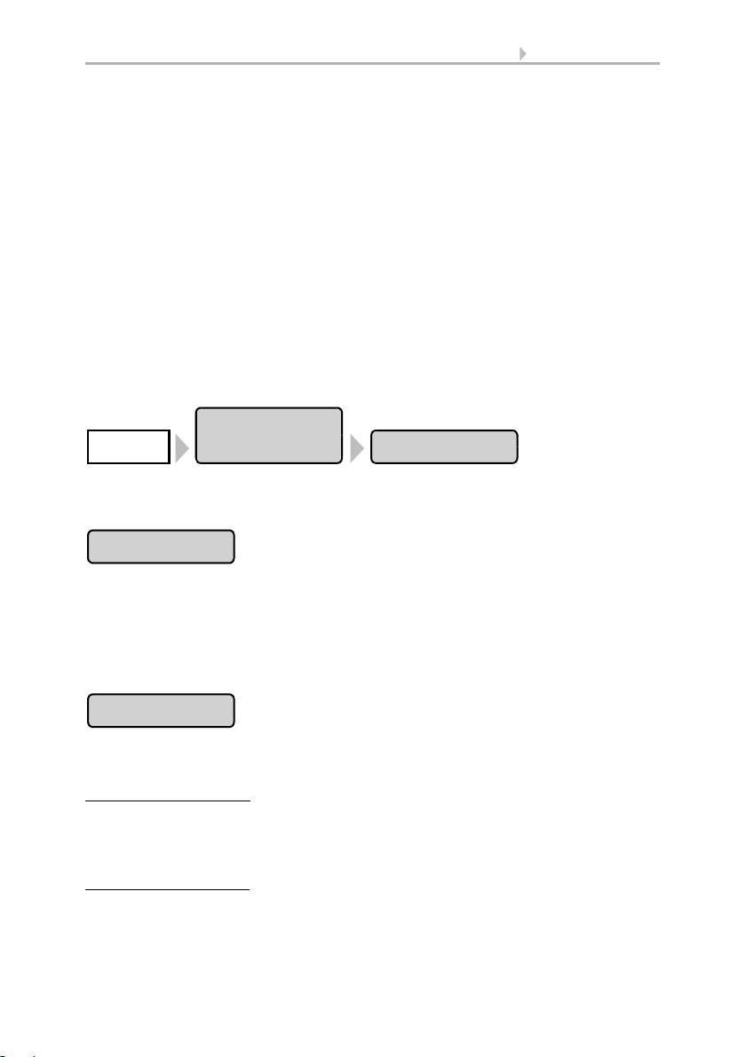
42 Automatic settings
Automatic
settings
WindowSystem
Sensor Selection
Indoor Temp.
Ventilation settings
The settings are only executed if a window is in automatic mode and none of the alarm
functions named above is active.
Highest priority is assigned to time closure, followed by the outdoor temperature-
block (keep closed), timed ventilation (open), the incoming air temperature-block
(keep closed) and night-time re-cooling (open).
This means that e.g. timed ventilation or night-time re-cooling will only occur, when
the outdoor temperature lies over the pre-set value for the outdoor temperature block.
The automatic ventilation according to temperature or relative humidity is only
performed if no block is active.
Setting of the automatic
The automatic window functions can be accessed by pressing the buttons:
Now you can select individual windows and adjust their settings. For each window the
following settings can be changed:
Press the button to select the indoor sensor the control system will use for this window
(Pre-setting: Internal sensor at WS1, first sensor in the list at WS1000). As long as “No
Sensor” is selected, the indoor temperature and air humidity will not be taken into account.
Confirm your setting with the OK button.
Press the button to set the indoor temperature above which the window will be
opened. Until an indoor sensor is selected, the indoor temperature will be disregarded.
Setting the temperature:
arrow buttons. Pre-setting: 25.0 °C.
The window is opened as soon as the temperature lies above the pre set value. It is
closed again once the temperature sinks more than 2.0°C under the pre-set value (hysteresis).
Shutting off ventilation:
press the button labelled OFF.
Confirm your setting with the OK button.
Adjust the value for the desired room temperature using the
If ventilation shall be independent of indoor temperature,
Control System WS1 Style / WS1000 Style • Version: 28.05.2018 • Technical changes and errors excepted.
Page 45

43 Automatic settings
Air Humidity
Supply-Air Temp.
Movem. Position
Only for sliding windows.
Number of steps
Only for step windows.
Press the button to set the air humidity above which the window will be opened. Until
an indoor sensor with humidity measurement is selected, the air humidity will be disregarded.
Setting air humidity:
Pre-setting: 80%.
The window is opened as soon as the humidity lies above the pre- set value. However,
it is only closed again when the humidity sinks by more than 3.0% under the pre-set
value (hysteresis).
Shutting off ventilation:
button labelled OFF.
Confirm your setting with the OK button.
Press the button to set the supply air temperature block (heat protection).
Enable:
If the window should be closed when the air supply temperature is higher than
the room temperature, select Yes.
The supply air temperature-block becomes active as soon as the incoming air temperature lies above the room temperature. The block is however only deactivated again
when the incoming air temperature sinks below the room temperature by more than
3.0°C (hysteresis).
Disable:
ture is higher than the room temperature, select No (default setting).
Confirm your setting with the OK button.
If the window should also then be/remain open when the supply air tempera-
Adjust the value for the desired humidity using the arrow buttons.
If ventilation is to be independent of the air humidity, press the
Press the button to set the movement position for a sliding window in automatic mode.
The window can also be fully opened by hand.
With the arrow keys, specify the movement position in % (0% = closed, 100% = fully
open). Default setting: 75%.
Confirm your setting with the OK button.
Press the button to set the number of movement steps for a step window in automatic
mode. With step windows the control unit checks every 3 minutes whether the set
room temperature or air humidity has been exceeded and then moves up another step
if necessary.
Control System WS1 Style / WS1000 Style • Version: 28.05.2018 • Technical changes and errors excepted.
Page 46

44 Automatic settings
Night-time cooling
NTC Indoor Temp.
NTC Movem. Pos.
Timed Ventilation
Specify the desired number of steps with the arrow keys. Default setting: 5.
Confirm your setting with the OK button.
Press the button to set the times for night-time re-cooling. The button is only activated
once the general settings for night-time re-cooling have been configured.
System > Automatic Settings > General Settings > Night-time Cooling
3.3. Set night-time re-cooling
Press Select to select the time during which the night-time re-cooling will operate. Activate one or more periods on the list.
Confirm your setting with the OK button.
To change any of the time periods, press Timer.
3.3. Set timer
Be careful that your settings for timed closure do not prevent night-time re-cooling operations!
Press the button to set the indoor temperature to the desired cooling level (for the
night-time re-cooling). The button is only activated once a night-time re-cooling period
has been set.
Use the arrow keys to change the value as required. Default setting: 16.0°C.
Confirm your setting by pressing OK.
Press the button to set the movement position for the night-time re-cooling. The button
is only activated once a night-time re-cooling period has been set.
Input the movement position in % using the arrow keys (0% = closed, 100% = fully
open). Default setting: 30%.
Confirm your setting by pressing OK.
Press the button to set the ventilation running time. However the window will only
open if the specified outdoor temperature is reached. At the end of a ventilation period,
the normal automatic ventilation according to temperature and air humidity will be executed.
Control System WS1 Style / WS1000 Style • Version: 28.05.2018 • Technical changes and errors excepted.
Page 47

45 Automatic settings
Movement Limitation
to Position
Outdoor Temp.
Press Select to select the time periods. Activate one or more periods on the list. The
periods can be individually customised (see below).
Confirm your setting by pressing OK.
To change any of the time periods, press Timer.
3.3. Set timer
Press the button to activate or deactivate the movement range limitation for this window at low outdoor temperatures.
The conditions for the triggering of the movement limitation (outdoor temperature, period) are defined in the "General Settings" menu.
System > Automatic Setttings > General Settings > Movement Limitation
3.3. Set movement limitations (windows)
Confirm your setting by pressing OK.
Press the button to set the movement position when movement limitation is active.
The button will only be activated once the movement limitation has been activated.
Input the maximum movement position in % using the arrow buttons (0% = closed,
100% = fully open). Default: 50%.
The window can be reopened fully by hand.
Confirm your setting using the OK button.
Confirm your setting by pressing OK.
Press the button to set the outdoor temperature block. The effect of the block is that the
window remains in the current position. The outdoor temperature block can, for example, be used if the window should not be used for ventilation in winter (cold protection
for plants).
The outdoor temperature block only applies for automatic operation; no ventilation
then takes place. When the rain or wind alarm is triggered, the window will be closed
despite the outdoor temperature block (the alarm has priority over temperature block).
Manual operation continues to remain possible, even when the window is blocked because of low outdoor temperatures.
Set value:
setting: 5.0°C
Control System WS1 Style / WS1000 Style • Version: 28.05.2018 • Technical changes and errors excepted.
Use the arrow buttons to change the value according to your wish. Default
Page 48

46 Automatic settings
Timed closure
Frost Alarm
The outdoor temperature-block becomes active as soon as the temperature sinks under the pre- set value. The block is however only deactivated again when the temperature rises over the pre-set value by more than 2.0°C (hysteresis).
Disable block:
If the window should be controlled independently of the outdoor tem-
perature, press the button Off.
Confirm your setting with the OK button.
Press the button to set the closure time. Closure periods prevent the windows, for example, from opening and closing at night, and thus causing noise. Note that no nighttime re-cooling is possible during the set closure periods.
Press Select to select the time during which the window should be closed. Activate
one or more periods on the list. The periods can be individually customised (see below).
Confirm your setting by pressing OK.
To change any of the time periods, press Timer.
3.3. Set timer
Press the button to activate or deactivate the frost alarm for this window. The frost
alarm closes the window if the outdoor temperature is low and it is raining/snowing at
the same time. This prevents damage from ice (e.g. at the seal).
The conditions for the triggering of the frost alarm (outdoor temperature, period) are
defined in the menu „General Settings“.
System > Automatic Settings > General Settings > Frost Alarm
3.3. Adjust frost alarm
In case of frost alarm there is no timed ventilation and no night time cooling.
When the frost alarm is triggered, manual operation of the window is initially blocked.
You can remove the block manually however. To do this select the appropriate window
in the Manual menu and press the frost alarm button. If the button is shown normally
(black writing), the block has been removed. The block will then be first active for this
drive again when it is reactivated manually or the next time the frost alarm is triggered.
Activate:
Deactivate:
If the window is to be closed when there is a frost alarm, select Yes.
If ventilation is to take place via the window regardless of the frost risk, se-
lect No (default setting).
Confirm your setting with the OK button.
Control System WS1 Style / WS1000 Style • Version: 28.05.2018 • Technical changes and errors excepted.
Page 49
47 Automatic settings
Wind Sensor
Wind Ventialtion
Only for step windows.
Wind Direction
Only for step windows
at WS1000 with KNX interface.
Wind Position
Only for step windows.
Press the button to select the wind sensor to be evaluated for controlling this window.
The button of the selected wind sensor is marked white (default setting: weather station on the "WS" controller). If no button is marked, the window does not react to wind.
Use the arrow buttons to set the response time for wind alarm (and wind ventilation
for step windows). Default: 1 second.
Confirm your setting with the OK button.
Drücken Sie die Taste um einzustellen, ab welcher Windstärke das Fenster bis auf einen Spalt zufahren soll. Wählen Sie einen Wert, der unter dem Windalarm-Wert liegt.
Erst bei Windalarm fährt das Fenster ganz zu (s. u.).
Set value:
Disable:
act to wind (default).
Confirm your setting with the OK button.
The wind direction can only be selected for step windows on WS1000 with
KNX interface! The wind direction must be received via the bus. The button is only
active if a value has been set for wind ventilation.
Press the button to set the range (wind direction) from which the wind must come so
that the window moves to the wind ventilation position.
All directions:
sides (default).
Direction:
there is wind from a certain direction, select the appropriate one: West, south-west,
south, south-east or east. The thickened part of the circle in the middle shows you
the selected area.
Enter the angle:
vated, press "from 0°" or "to 360°" and adjust the numerical values with the arrow buttons that appear.
Confirm your setting with the OK button.
Use the arrow buttons to adjust the value for the wind speed.
If you do not want the window to react to low wind speeds, select Do not re-
If the wind direction is not decisive for wind ventilation, select from all
If you only want the window to move to the wind ventilation position when
To specify the exact numerical range in which wind ventilation is acti-
Press the button to set the driving position for ventilation in wind. The button is only
active if a value has been set for wind ventilation.
Control System WS1 Style / WS1000 Style • Version: 28.05.2018 • Technical changes and errors excepted.
Page 50

48 Automatic settings
Wind Alarm
Rain Alarm
Gap Ventilation
Use the arrow buttons to enter the maximum travel position in % (0% = closed,
100% = fully open). Default: 15%.
The window can still be opened completely by hand.
Confirm your setting with the OK button.
Press the button to set the wind alarm. The wind alarm protects the unit and equipment
from damage by closing the window. The wind alarm will also close manually opened
windows.
Adjust values:
Use the arrow keys to adjust the value for wind speed and the length of
time by which it must have been exceeded (default setting 8 m/s).
Disable:
If the window should not react to the wind, select Never close.
Confirm your setting with the OK button.
A wind alarm triggered for the drive will be maintained for 5 minutes. If during these 5
minutes the saved value is exceeded again, the holding time begins again.
Press the button to enable or disable the rain alarm. The rain alarm protects against
moisture damage by closing the window. The rain alarm will also close manually
opened windows.
Enable:
If the window should be closed when there is rain, select Yes.
Disable:
If the window should remain open when there is rain, select No (default set-
ting).
Confirm your setting with the OK button.
Press the button to enable or disable gap opening when a rain alarm triggers. The function is only active if the rain alarm is switched on. With gap opening, the window can
be opened a little despite a rain alarm.
Enable:
ATTENTION
Material damage through penetrating precipitation!
Depending on the amount of rain and temperature, some time passes
before precipitation is detected by the weather station.
•Do not place moisture-sensitive objects in the area of automatic
windows.
•Include operating time to close the window in calculation.
If gap opening should be active when it rains, select Yes.
Control System WS1 Style / WS1000 Style • Version: 28.05.2018 • Technical changes and errors excepted.
Page 51

49 Automatic settings
Gap Position
Automatic Reset
Disable: If the window should be completely closed when there is rain, select No (default setting).
Confirm your setting with the OK button.
Please note that gap ventilation is not possible if the MSG Control has been activated
(signal duration set to permanent) in the basic settings of the window in the installation
menue.
6.1. Set up drives and drive groups
Press the button to set the movement position for the opening when a rain alarm triggers. The function is only active if the gap ventilation is switched on.
With the arrow keys, specify the movement position in % (0% = closed, 100% = fully
open). Default setting: 5%.
Confirm your setting with the OK button.
Press the button to enable or disable the switchover to automatic mode at a set point
in time, or following a manual intervention.
The general Automatic Reset occurs daily at the same time.
Switching on:
the default setting).
Switching off:
Alternatively, the automatic function can be reactivated at a set time following a manual intervention.
Switching on:
Switching off:
setting).
Confirm your setting with the OK button.
Automatic Reset time and/or period can be set.
System > Automatic Settings > General Settings > Automatic Reset
3.3. Define automatic reset
To set the window to Automatic at a set point in time, select Yes (this is
To switch off the window’s Reset function, select No.
To perform an Automatic Reset after a manual intervention, select Yes.
To switch off the window’s Reset function, select No (this is the default
3.1.7. Automatic ventilation settings
For connected roof ventilation units and supply air units the following automatic settings can be changed:
• Indoor sensor to be used for the ventilation unit
• Indoor temperature
Control System WS1 Style / WS1000 Style • Version: 28.05.2018 • Technical changes and errors excepted.
Page 52

50 Automatic settings
Automatic
Settings
VentilationSystem
Sensor Selection
For all ventilation units.
• Air humidity
•CO
(only if a CO2 sensor is installed)
2
• Air supply temperature (only for air supply devices)
• Exhaust air levels / exhaust air intensity (only for roof ventilators WL400/800 an
ventilators at RF-VM)
• Night-time re-cooling (together with indoor temperature for night-time re-
cooling)
• Timed ventilation (and levels for timed ventilation)
• Outdoor temperature (only for air supply devices)
• Recirculating air for heat recovery (only roof ventilators WL400/800)
• Recirculating air for condensation reduction (only for roof ventilators WL400/
800)
• Temperature for heating (only for fresh air/heating-combos on RF-VM)
• Enable/Disable automatic reset
In the event of a fire alarm from a smoke detector, ventilation is activated and cannot
be influenced by either the automatic or the manual.
As soon as a connected air conditioner is activated, ventilation is disabled, including
manually activated fans. The fans can be manually operated again immediately. The
delay time for the ventilation block can be adjusted.
System > Automatic Settings > General Settings > Ventilation Block
3.3. Adjust ventilation block
Ventilation according to temperature, humidity and CO
For exhaust air units (radio roof ventilation units, units at RF-VM), the more one of the
is checked every second.
2
values is above the setpoint value, the higher the air flow rate is increased. However,
the air flow rate is only reduced again when the new required ventilation level is 20%
lower than the current one (delay/hysteresis). The set minimum and maximum ventilation intensity is maintained.
In supply air units (WL-Z unit at MF output or radio relay), the ventilation flap is opened
as soon as one of the values is above the adjusted setpoint. However, it is only closed
again when the new required ventilation level is 20% lower than the current one (delay/
hysteresis).
The automatic ventilation functions can be accessed by pressing the buttons:
Now you can select individual ventilators and adjust their settings. For each ventilator
the following settings can be changed:
Press the button to select the indoor sensor the control system will use for this ventilator (Pre-setting: Internal sensor at WS1, first sensor in the list at WS1000). As long as
“No Sensor” is selected, the indoor temperature and air humidity will not be taken
into account by the control system for this ventilator.
Control System WS1 Style / WS1000 Style • Version: 28.05.2018 • Technical changes and errors excepted.
Page 53

51 Automatic settings
Indoor Temp
For all ventilation units.
Temp. Ventilation
Air Humidity
For all ventilation units.
Humidity Ventil.
CO2
For all ventilation units but only if a CO2 sensor is
installed.
Supply-Air Temp.
Only for WL-Z
and ventilation units at MF output/RF Relay.
Confirm your setting with the OK button.
Press the button to set the indoor temperature above which the ventilation will be
switched on at night. Until an indoor sensor is selected, the indoor temperature will be
disregarded.
Setting the temperature:
Adjust the value for the desired room temperature using the
arrow buttons. Pre-setting: 21.0 °C.
Shutting off ventilation:
If ventilation is to be independent of indoor temperature, press
the button labelled OFF.
Confirm your setting with the OK button.
Press the button to set the air humidity above which the ventilation will be switched on
at night. Until an indoor sensor is selected, the air humidity will be disregarded.
Setting humidity:
Adjust the value for the desired humidity using the arrow buttons.
Pre-setting: 80%.
Shutting off ventilation
: If ventilation is to be independent of air humidity, press the
button labelled OFF.
Confirm your setting with the OK button.
Press the button to set the CO
CO
Setting CO
at the lowest preset speed. Default: 700 ppm.
Use the lower arrow keys to set the value at which ventilation takes place at the highest
specified speed. Default: 1500 ppm.
The speed is automatically adjusted between the two values.
Shutting off ventilation:
Off button.
Confirm your setting with the OK button.
Press the button to set the supply air temperature block (summer operation). With WLZ supply air units, the supply air temperature is recorded by a thermometer integrated
into the WL-Z. With devices from other manufacturers the outdoor temperature at the
weather station is used as the supply air temperature.
content of the room air to be ventilated. As long as no
sensor is selected, the CO2 content is not taken into account.
2
: Use the upper arrow keys to set the value from which the ventilation starts
2
2
If ventilation is to be independent of the CO2 content, press the
Control System WS1 Style / WS1000 Style • Version: 28.05.2018 • Technical changes and errors excepted.
Page 54

52 Automatic settings
Exhaus Air Levels
Only for air supply on RF-VM.
Ventilation Levels
Min. Exhaust Level
Only for WL400/800.
Max. Exhaust Level
Night-time Cooling
Not on fresh air/heating-combos on RF-VM.
Enable: If the supply air unit should be closed when the supply air temperature is
warmer than the room temperature, select Yes.
Disable:
perature is warmer than the room temperature, select No (default setting).
Confirm your setting with the OK button.
Press the button to set the ventilation levels of the motorised roof ventilators. The further the indoor temperature and air humidity lie above the reference values, the higher
the ventilator shifts.
Use the arrow buttons to change the start and maximum values according to your
wishes. Default setting: Start with level 1, maximum level 8 (full level utilisation).
Confirm your setting with the OK button.
Press the button to set the minimum and maximum ventilation speed of the motorised
roof ventilators. The further the indoor temperature and air humidity lie above the reference values, the higher the ventilator shifts.
Use the arrow buttons to change the start and maximum values according to your
wishes. Default setting: Start with 0%, maximum 100% (full level utilisation).
Confirm your setting with the OK button.
If the supply air unit should also then be/remain open when the supply air tem-
Press the button to set the times for night-time re-cooling. The button is only activated
once the general settings for night-time re-cooling have been configured.
System > Automatic Settings > General Settings > Night-time Cooling
3.3. Set night-time re-cooling (ventilation)
Press Select to select the time during which the night-time re-cooling will operate. Activate one or more periods on the list.
Confirm your setting with the OK button.
To change any of the time periods, press Timer.
3.3. Set timer
Be careful that your settings for timed closure do not prevent night-time re-cooling operations! A set supply air temperature block can also prevent night-time re-cooling.
Control System WS1 Style / WS1000 Style • Version: 28.05.2018 • Technical changes and errors excepted.
Page 55

53 Automatic settings
NTC Indoor Temp.
NTC Exhaust Level
Only for WL400/800.
NTC Intensity
Timed Ventilation
For all ventilation units.
Ventilation Level
Nur bei WL400/800.
Ventilation Intesity
Outdoor Temp
Only for WL-Z
and ventilation units at MF output/RF Relay.
Press the button to set the indoor temperature to the desired cooling level (for the
night-time re-cooling). The button is only activated once a night-time re-cooling period
has been set.
Use the arrow keys to change the value as required. Default setting: 16.0°C.
Confirm your setting by pressing OK.
Press the button to set the ventilation levels (intensity) of the motorised roof ventilators
for the night-time re-cooling. The button is only activated once a night-time re-cooling
period has been set.
Use the arrow buttons to change the level according to your desire. Default setting:
Level 3.
Confirm your setting with the OK button.
Press the button to set the timed ventilation. Press Select to select the time during
which ventilation will occur. However supply air flaps are only opened if the set outdoor temperature is hit.
Activate one or more periods on the list. Confirm your setting by pressing OK.
To change any of the time periods, press Timer.
Set timer, page 59
Press the button to set the ventilation levels (intensity) of the motorised roof ventilators
for the timed ventilation. The button is only active if a ventilation time has been set.
Use the arrow buttons to change the level according to your desire. Default setting:
Level 3.
Confirm your setting with the OK button.
Press the button to set the outdoor temperature above which the supply air unit should
remain closed (winter operation). Use the arrow buttons to change the value according
to your wish. Default setting: 1.0 °C.
Control System WS1 Style / WS1000 Style • Version: 28.05.2018 • Technical changes and errors excepted.
Page 56

54 Automatic settings
Heat Recovery
Only for roof ventilators WL400/800.
Condensation
Only for roof ventilators WL400/800.
Temp. Heating
Only for fresh air/heating-combos on RF-VM.
Night mode
Only for fresh air/heating-combos on RF-VM.
Confirm your setting with the OK button.
Press the button to set the recirculating air function for heat recovery. Recirculation allows heated air from the first area to be distributed in the entire room and so be used
for warming if required. In principle, the recirculation function only starts if the temperature at the ventilator is at least 3° warmer than the indoor temperature.
Select Yes to activate the heat recovery function (with No, the function is switched off).
Use the arrow keys that appear to set the indoor temperature beneath which circulation should take place, and the level at which the ventilator should run.
Default setting: Indoor temperature 10.0°C lower; with 30%.
Confirm your setting with the OK button.
Press the button to set the recirculating air function for condensation reduction. Recirculation of the air can reduce condensation forming on the window panes.
Select Yes to activate the condensation reduction function (with No, the function is
switched off). Using the arrow keys that appear, set the U-value of the glass used (ask
your window manufacturer or conservatory supplier for the value) and the level at
which the ventilator should run. Default setting: U-value 1.0; with 30%.
Confirm your setting with the OK button.
Press the button to set the indoor temperature above which the circulating air heating
will be switched on during the day. Until an indoor sensor is selected, the automatic
heating is deactivated. Use the arrow buttons to change the value according to your
wish. Default setting: 16.0 °C.
Confirm your setting with the OK button.
Press the button to set the night-time operation for the circulating air heating. Press
Select to select the time during which the night mode will operate. Activate one or
more periods on the list. The periods can be individually customised (see below).
Confirm your setting with the OK button.
To change any of the time periods, press Timer.
3.3. Set timer
Control System WS1 Style / WS1000 Style • Version: 28.05.2018 • Technical changes and errors excepted.
Page 57

55 Automatic settings
Indoor Temp. Night
Automatic Reset
For all ventilation units.
Ventilator
OFF
(stopped,
Exhaust air
0% ... 100%
Flap open
+
-
For circulation air
100% ... 0%
Flap open
Press the button to set the indoor temperature above which the heating will be
switched on at night. The button is only active if a night mode operation period has
been set. Use the arrow buttons to change the value according to your wish. Default
setting: 9.0°C
Confirm your setting with the OK button.
Press the button to enable or disable the switchover to automatic mode at a set point
in time, or following a manual intervention.
The general Automatic Reset occurs daily at the same time.
Switching on:
(this is the default setting).
Switching off:
Alternatively, the automatic function can be reactivated at a set time following a manual intervention.
Switching on:
Switching off:
default setting).
Confirm your setting with the OK button.
Automatic Reset time and/or period can be set.
System > Automatic Settings > General Settings > Automatic Reset
3.3. Define automatic reset
To set the ventilation unit to Automatic at a set point in time, select Yes
To switch off the ventilation unit’s Reset function, select No.
To perform an Automatic Reset after a manual intervention, select Yes.
To switch off the ventilation unit’s Reset function, select No (this is the
Ventilation modes wireless roof ventilator
Ventilation modes for WL400 and WL800:
Each time the OFF state is reached, the speed change stops automatically, so that a
direct change between exhaust and circulation modes is impossible.
Control System WS1 Style / WS1000 Style • Version: 28.05.2018 • Technical changes and errors excepted.
Page 58

56 Automatic settings
Automatic
Settings
Air ConditionerSystem
Sensor Selection
Indoor Temp. Day
Night mode
3.1.8. Automatic heating settings
For connected heatings the following automatic settings can be changed:
• Indoor sensor to be used for the heating
• Indoor day temperature
• Night mode (period) and indoor night temperature
• Enable/Disable automatic reset
The automatic heating functions can be accessed by pressing the buttons:
Now you can select individual heatings and adjust their settings. For each heating the
following settings can be changed:
Press the button to select the indoor sensor the control system will use for this heating
(Pre-setting: Internal sensor at WS1, first sensor in the list at WS1000). For as long as
“No sensor” is selected, the indoor sensor will not be taken into account for control
of the heating, i.e. no automatic control will take place.
Confirm your setting with the OK button.
Press the button to set the indoor temperature above which the heating will be
switched on during the day. Until an indoor sensor is selected, the automatic heating
is deactivated. Use the arrow buttons to change the value according to your wish. Default setting: 20.0 °C.
Confirm your setting with the OK button.
The heating will engage as soon as the temperature drops below the set value and is
shut down again when the temperature is more than 0.5°C above the set value (hysteresis).
Press the button to set the night-time operation. Press Select to select the time during
which the night mode will operate. Activate one or more periods on the list. The periods can be individually customised (see below).
Confirm your setting with the OK button.
Control System WS1 Style / WS1000 Style • Version: 28.05.2018 • Technical changes and errors excepted.
Page 59

57 Automatic settings
Indoor Temp. Night
Automatic Reset
To change any of the time periods, press Timer.
3.3 Set timer
Press the button to set the indoor temperature above which the heating will be
switched on at night. The button is only active if a night mode operation period has
been set. Use the arrow buttons to change the value according to your wish. Default
setting: 16.0°C
Confirm your setting with the OK button.
The heating will engage as soon as the temperature drops below the set value and is
shut down again when the temperature is more than 0.5°C above the set value (hysteresis).
Press the button to enable or disable the switchover to automatic mode at a set point
in time, or following a manual intervention.
The general Automatic Reset occurs daily at the same time.
Switching on:
the default setting).
Switching off:
Alternatively, the automatic function can be reactivated at a set time following a manual intervention.
Switching on:
Switching off:
setting).
Confirm your setting with the OK button.
Automatic Reset time and/or period can be set.
System > Automatic Settings > General Settings > Automatic Reset
3.3. Define automatic reset
To set the heating to Automatic at a set point in time, select Yes (this is
To switch off the heating’s Reset function, select No.
To perform an Automatic Reset after a manual intervention, select Yes.
To switch off the heating’s Reset function, select No (this is the default
3.1.9. Automatic air-conditioner settings
For connected coolings/air conditioners the following automatic settings can be
changed:
• Indoor sensor to be used for the air-conditioner
• Indoor day temperature
• Night mode (period) and indoor night temperature
• Enable/Disable automatic reset
Control System WS1 Style / WS1000 Style • Version: 28.05.2018 • Technical changes and errors excepted.
Page 60

58 Automatic settings
Automatic
Settings
Air conditionerSystem
Sensor Selection
Indoor Temp. Day
Night mode
As soon as a cooling/air-conditioning unit is activated, windows will be closed and
ventilators switched off. The delay time applicable to this can be set.
System > Automatic Settings > General Settings > Ventilation Block
3.3. Adjust ventilation block
The automatic climate control functions can be accessed by pressing the buttons:
Now you can select individual air conditioners and adjust their settings. For each air
conditioner the following settings can be changed:
Press the button to select the indoor sensor the control system will use for this cooling
unit (Pre-setting: Internal sensor at WS1, first sensor in the list at WS1000). For as long
as “No sensor” is selected, the indoor sensor will not be taken into account for control
of the cooling unit, i.e. no automatic control will take place.
Confirm your setting with the OK button.
Press the button to set the indoor temperature above which the cooling unit will be
switched on during the day. Until an indoor sensor is selected, the automatic cooling
is deactivated. Use the arrow buttons to change the value according to your wish. Default setting: 30.0°C
Confirm your setting with the OK button.
The cooling will engage as soon as the temperature exceeds the set value and is shut
down again when the temperature is more than 2°C below the set value (hysteresis).
Press the button to set the night-time operation. Press Select to select the time during
which the night mode will operate. Activate one or more periods on the list. The periods can be individually customised (see below).
Confirm your setting with the OK button.
To change any of the time periods, press Timer.
3.3. Set timer
Control System WS1 Style / WS1000 Style • Version: 28.05.2018 • Technical changes and errors excepted.
Page 61

59 Automatic settings
Indoor Temp. Night
Automatic Reset
Automatic
Settings
LightSystem
Press the button to set the indoor temperature above which the cooling will be
switched on at night. The button is only active if a night mode operation period has
been set. Use the arrow buttons to change the value according to your wish. Default
setting: 34.0°C.
Confirm your setting with the OK button.
The cooling will engage as soon as the temperature exceeds the set value and is shut
down again when the temperature is more than 2°C below the set value (hysteresis).
Press the button to enable or disable the switchover to automatic mode at a set point
in time, or following a manual intervention.
The general Automatic Reset occurs daily at the same time.
Switching on:
(this is the default setting).
Switching off:
Alternatively, the automatic function can be reactivated at a set time following a manual intervention.
Switching on:
Switching off:
default setting).
Confirm your setting with the OK button.
Automatic Reset time and/or period can be set.
System > Automatic Settings > General Settings > Automatic Reset
3.3. Define automatic reset
To set the air conditioner to Automatic at a set point in time, select Yes
To switch off the air conditioner’s Reset function, select No.
To perform an Automatic Reset after a manual intervention, select Yes.
To switch off the air conditioner’s Reset function, select No (this is the
3.1.10.Automatic light settings
For connected lights the following automatic settings can be changed:
• Time switches
• Twilight operation
• Alarm reaction
• Enable/Disable automatic reset
The automatic lighting functions can be accessed by pressing the buttons:
Control System WS1 Style / WS1000 Style • Version: 28.05.2018 • Technical changes and errors excepted.
Page 62

60 Automatic settings
Time Switch
Twilight
Alarm
Automatic Reset
Now you can select individual lights and adjust their settings. For each light the following settings can be changed:
Press the button to set the time switch. Press Select to select the time during which
the lights will be turned on. As soon as you activate the twilight setting (see below), the
light will only be turned on at twilight in the selected time periods. Activate one or
more periods on the list.
Confirm your setting with the OK button.
To change any of the time periods, press Timer.
3.3. Set timer
Press the button to enable or disable the twilight/night switch. If the twilight setting is
active, the light is only turned on at twilight in the time periods selected above. Presetting: No (twilight switching off).
Confirm your setting with the OK button.
The threshold value, above which twilight/night will be recognised, can be adjusted.
System > Automatic Settings > Twilight
3.3. Adjust twilight value
Press the button to set the alarm response. When an alarm is triggered in a connected
motion or smoke detector, the lighting can be switched on automatically.
Enable:
select Yes.
Disable:
gered, select No (default setting).
Confirm your setting with the OK button.
Press the button to enable or disable the switchover to automatic mode at a set point
in time, or following a manual intervention.
The general Automatic Reset occurs daily at the same time.
Switching on:
default setting).
Switching off:
If the lighting should be switched on automatically when an alarm is triggered,
If the lighting should not be switched on automatically when an alarm is trig-
To set the light to Automatic at a set point in time, select Yes (this is the
To switch off the light’s Reset function, select No.
Control System WS1 Style / WS1000 Style • Version: 28.05.2018 • Technical changes and errors excepted.
Page 63

61 Automatic settings
Automatic
Settings
Gutter HeatingSystem
Temperature Range
Automatic Reset
Alternatively, the automatic function can be reactivated at a set time following a manual intervention.
Switching on:
Switching off
ting).
Confirm your setting with the OK button.
Automatic Reset time and/or period can be set.
System > Automatic Settings > General Settings > Automatic Reset
3.3. Define automatic reset
To perform an Automatic Reset after a manual intervention, select Yes.
: To switch off the light’s Reset function, select No (this is the default set-
3.1.11.Automatic roof gutter heating settings
For connected roof gutter heatings the following automatic settings can be changed:
• Temperature range within which the heating will be switched on
• Enable/Disable automatic reset
The automatic gutter heating functions can be accessed by pressing the buttons:
Now you can select individual roof gutter heatings and adjust their settings. For each
heating the following settings can be changed:
Use the arrow keys to set the temperature range within which the roof gutter heating
will be switched on. If the temperatures are very cold, no condensate forms and the
heating can remain switched off. Default setting: 5.0°C to -5.0°C.
Confirm your setting with the OK button.
Press the button to enable or disable the switchover to automatic mode at a set point
in time, or following a manual intervention.
The general Automatic Reset occurs daily at the same time.
Switching on:
(this is the default setting).
Switching off:
Alternatively, the automatic function can be reactivated at a set time following a manual intervention.
Control System WS1 Style / WS1000 Style • Version: 28.05.2018 • Technical changes and errors excepted.
To set the gutter heating to Automatic at a set point in time, select Yes
To switch off the gutter heating’s Reset function, select No.
Page 64

62 Automatic settings
Automatic
Settings
AlarmSystem
Switching on: To perform an Automatic Reset after a manual intervention, select Yes.
Switching off:
default setting).
Confirm your setting with the OK button.
Automatic Reset time and/or period can be set.
System > Automatic Settings > General Settings > Automatic Reset
3.3. Define automatic reset
To switch off the gutter heating’s Reset function, select No (this is the
3.1.12.Set up alarm
You can select the alarm source which should activate the alarm output relay here. The
alarm settings can be accessed by pressing the buttons:
First select the alarm output that you want to set.
Select the alarm source which should activate the alarm output relay. More than one
source can also be selected:
• Smoke detector (multifunctional output)
• Motion detector (multifunctional output)
• Rain alarm from weather station
• Wind alarm. Adjust the values for wind speed and duration of the exceedance.
A triggered wind alarm will be maintained for 5 minutes. If during these 5
minutes the saved value is exceeded again, the holding time begins again
• Frost alarm of the control
Confirm your setting with the OK button.
3.1.13.Setting motion detectors
If a motion-detector is connected, a period of time during which the control system will
react to the movements detected can be set (severe alarm). If an alarm is triggered
within this time, all windows will close for around 5 minutes. The display (starting position with weather data display) reads "Motion-detector alarm." After 5 minutes without a new alarm signal, normal automatic operation will be resumed.
Note: Even manually opened windows will be closed when there is a motion-detector
alarm!
If a multifunctional output is configured as an alarm output, it closes for the duration
of the alarm signal.
3.2. Set up alarm
Lights can also be switched on when the alarm is active.
3.2. Automatic light settings
Control System WS1 Style / WS1000 Style • Version: 28.05.2018 • Technical changes and errors excepted.
Page 65
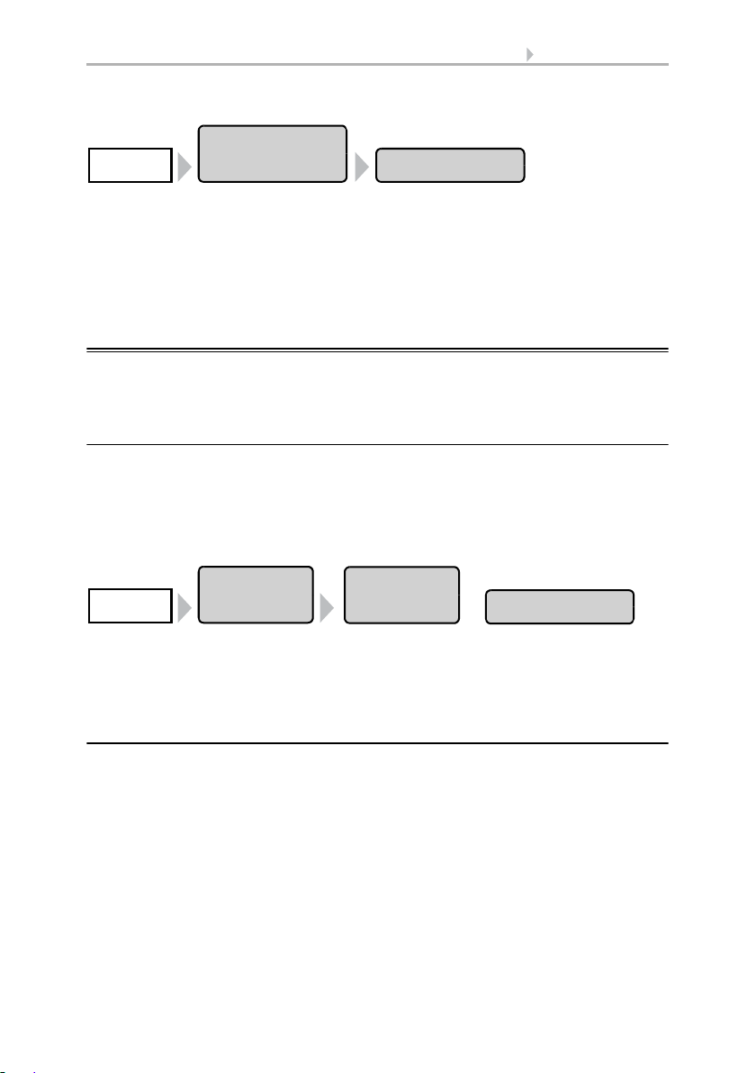
63 Automatic settings
Automatic
Settings
Motion DetectorSystem
Automatic
Settings
Twilight
System
General
Settings
The motion-detector settings can be accessed by pressing the buttons:
First select the motion detector that you want to set. Press Select to select the time
during which the motion detector alarm should be active. Activate one or more periods
on the list. The operating times can be individually customised (see below).
Confirm your setting with the OK button.
To change any of the time periods, press Timer.
3.3. Set timer
3.2. Adjust general automatic settings
The settings applied here are used for all drives and devices, or are applicable to the
drive types defined in the relevant chapter (e.g. for all shades).
3.2.1. Adjust twilight value
You can adjust the threshold value above which twilight/night will be recognised. Note
that on moonlit nights, brightness values short below 10 lux can be achieved. If the twilight value is set below 10 lux, shades which are set to “close at night” will remain open
because of the moonlight or retract during the night.
The twilight settings can be accessed by pressing the buttons:
Use the arrow keys to set the value above which twilight or night will be recognised by
the control unit. Default setting: 10 Lux.
Confirm your setting with the OK button.
3.2.2. Adjust movement delays (shading elements)
You can adjust the delay time for shades. The movement delay prevents sun shades
from being constantly extended and retracted when there are rapidly changing light
conditions.
For the shade to extend, the brightness must lie above the set light intensity value uninterruptedly for the set extension delay time (e.g. 1 minute). For the shade to retract
again, the light intensity for the set retraction delay time must lie below the value without interruption for the set retraction delay time (e.g. 12 minutes). Clever selection of
the delay time “masks out” passing clouds and nonetheless permits the shade to react
quickly to the sun.
Control System WS1 Style / WS1000 Style • Version: 28.05.2018 • Technical changes and errors excepted.
Page 66

64 Automatic settings
Automatic
Settings
Movement Delays
System
General
Settings
Automatic
Settings
Timer
System
General
Settings
Period 1
The movement delay settings can be accessed by pressing the buttons:
Use the arrow keys to set the values for the extension and retraction delays.
Default setting: Extension 1 minute, retraction 12 minutes.
Confirm your setting with the OK button.
3.2.3. Set timer
Sixteen periods can be set in the week-long timer, which can be used for different automation functions. A start and end point, as well as a day of the week must be set for
each time period.
The timer settings can be accessed by pressing the buttons:
In the illustration, the times for mandatory closing and opening the windows on weekdays and weekends have already been set.
Select the time period that you want to change. The following settings of each time period can be changed:
Name of the time period:
Press the button to change this name. Input the desired name on the on-screen keyboard which appears.
2.4. Input keyboard for names and codes
Control System WS1 Style / WS1000 Style • Version: 28.05.2018 • Technical changes and errors excepted.
Page 67

65 Automatic settings
Automatic
Settings
Ventilation Block
System
General
Settings
Start / end:
Set the start and end of the time period by selecting each hour and minute field consecutively and setting the time using the arrow keys.
Weekdays:
Select the day of the week on which the time period should be activated. More than
one day can also be selected.
Confirm your setting with the OK button.
3.2.4. Adjust ventilation block
As soon as a cooling/air-conditioning unit is activated, windows will be closed and
ventilators switched off. If the cooling is switched off again, the ventilation will stay off
for a while, to prevent the cooled air to be discharged immidiately through windows
or ventilation units. You can adjust the delay time for this.
The ventilation block is also iniciated by devices that are connected to the multifunction input as climate signallers.
The ventilation block settings can be accessed by pressing the buttons:
Use the arrow keys to set how many minutes ventilation via windows or ventilators
should remain blocked after an air-conditioning device is switched off.
Default setting: 120 minutes.
Confirm your setting with the OK button.
3.2.5. Set night-time re-cooling (ventilation)
The night-time re-cooling function using the windows and ventilation equipment is activated once a set outdoor temperature is exceeded for an extended period of time.
The weather data display (Start screen) then shows “Night-time re-cooling” next to the
outdoor temperature value. The display can also show “Frost alarm” and “Window
movement limitation” in turn.
2.1. Weather data display (start screen)
The window(s) and ventilator(s) which are used for night-time re-cooling as well as the
time period over which these are activated can be set in the automatic operation functions for the individual windows and ventilators.
Control System WS1 Style / WS1000 Style • Version: 28.05.2018 • Technical changes and errors excepted.
Page 68

66 Automatic settings
Automatic
Settings
Night-time Cooling
System
General
Settings
The night-time re-cooling settings can be accessed by pressing the buttons:
Using the arrow keys, set the outdoor temperature at which the night-time re-cooling
shall be active (e. g. higher than 20°C). Remember that the night-time re-cooling only
starts when the outdoor temperature is more than 2.0°C above the pre-set value. The
night-time re-cooling is de-activated again as soon as the outdoor temperature drops
below the pre-set value.
Also set the period for which the outdoor temperature must have been above the minimum temperature (e. g. longer than 48 hours).
Confirm your setting with the OK button.
Night-time re-cooling will stop when the set outdoor temperature is undercut by 2°C
for a specified period of time. This period depends on the set trigger period and on how
long this temperature has been exceeded. It is a maximum of one third of the set trigger period (e.g. max. 12 hours for a 48-hour trigger period).
3.2.6. Adjust frost alarm
The frost alarm for shades and windows will be active when during or after precipitation the outdoor temperature falls below a defined level.
The weather data display (Start screen) then shows “Frost alarm” next to the outdoor
temperature value. The display can also show “Night-time re-cooling” and “Window
movement limitation” in turn.
2.1. Weather data display (start screen)
You adjust which shades will be retracted and which windows will be closed in the automatic functions for the individual shades and windows. The frost alarm blocks all automatic functions and manual operation for these drives.
The following situations trigger the frost alarm:
• The outdoor temperature is below the set frost alarm temperature and ist starts
to rain/snow.
• The outdoor temperature falls below the set frost alarm temperature while it is
raining/snowing.
• Rain/snow has stopped. The outdoor temperature falls belowing the set frost
alarm temperature within the set standby period after the end of precipitation.
The following situation stops the frost alarm:
• The outdoor temperature stays above the set unfreezing temperature for the
set time period.
Setting of the frost alarm:
Control System WS1 Style / WS1000 Style • Version: 28.05.2018 • Technical changes and errors excepted.
Page 69

67 Automatic settings
Automatic
Settings
Frost Alarm
System
General
Settings
Automatic
Settings
Movement Limitation
System
General
Settings
You can reach the frost alarm settings by pressing the buttons:
First set when the frost alarm should be triggered. Use the arrow keys to adjust the outdoor temperature that must be undercut to trigger the frost alarm (e.g. 2.0°C).
Then set how many hours after precipitation the standby for the frost alarm should be
active (e.g. 5 hrs). Choose the standby period so that all humidity of the previous precipitation has dried.
Then set the conditions for the end of the frost alarm. Set the outdoor temperature to
be exceeded (e.g. 5.0°C) and the duration for which it should be exceeded (e.g. 5 hrs).
Choose the time period so that ice is completely melted thereafter.
The Off button lets you deactivate the frost alarm for all shades and windows.
Confirm your setting with the OK button.
3.2.7. Set movement limitations (window)
A movement limitation ensures that a window remains only open a portion at low outdoor temperatures. This prevents the room from cooling too rapidly.
The weather data display (Start screen) then shows “Window movement limitation”
next to the outdoor temperature value. The display can also show “Night-time re-cooling” and “Frost alarm” in turn.
2.1. Weather data display (start screen)
You can set the degree to which the opening is restricted for individual windows in the
automatic functions.
You can reach the movement limitation settings by pressing the buttons:
First define the outdoor temperature below which the window movement range becomes limited (e.g. 2.0°C).
You can then set how long the outdoor temperature must remain above the set limit
value, so that the movement limitation is cancelled again (e.g. 8 hours).
The Off button lets you deactivate the movement limitation for all windows.
Confirm your setting with the OK button.
Control System WS1 Style / WS1000 Style • Version: 28.05.2018 • Technical changes and errors excepted.
Page 70

68 Automatic settings
Automatik
einstellen
Windverzögerung
System
Allgemeine
Einstellungen
Automatic
Settings
Automatic Reset
System
General
Settings
3.2.8. Setting a wind delay (shades)
When the wind limitation value is exceeded for a drive, the wind alarm is then triggered
for 5 minutes. If the wind value is once again exceeded within this period, the 5-minute
stop time restarts from scratch.
For shades, a delay time can also be set following the wind alarm, during which the
shade automation is blocked. This means that if the shade is in automatic mode before
a wind alarm, the automatic setting remains switched off after the wind alarm. Further
manual operation is however possible again.
You can reach the wind delay time settings by pressing the buttons:
Set the duration of the shade block after a wind alarm using the arrow keys (0-360 minutes, default setting: 0 minutes).
Confirm your setting with the OK button.
3.2.9. Define automatic reset
Following a manual intervention, the affected drive or unit remains in manual mode,
and automatic operations are switched off. Once the general Automatic Function time
point is reached, drives and units are once again set to Automatic. Alternatively, the
automatic function can be set to reactivate following a manual intervention. The period
for this can be set.
The Automatic Reset prevents drives from being manually operated and then stay in
an unfavourable position (leaving windows accidentally open, or blinds retracted despite the sunlight).
The general Automatic Reset and reset following a manual intervention can be separately activated and de-activated in the Automatic functions menu for each drive group
and each unit.
The Automatic Reset function settings can be accessed by pressing the buttons:
General Automatic Reset
Set the time point by selecting the hour and accordingly the minute fields and setting
the time using the arrow buttons. Default setting: 3:00 AM.
Control System WS1 Style / WS1000 Style • Version: 28.05.2018 • Technical changes and errors excepted.
Page 71

69 Automatic settings
Automatic reset following a manual intervention
Use the arrow keys to set the time interval after which Automatic functions should be
once again activated.Default setting: 60 minutes.
Confirm your setting with the OK button.
Control System WS1 Style / WS1000 Style • Version: 28.05.2018 • Technical changes and errors excepted.
Page 72

70 Automatic settings
Control System WS1 Style / WS1000 Style • Version: 28.05.2018 • Technical changes and errors excepted.
Page 73

71 Installation
4. Installation
Control System WS1 Style / WS1000 Style • Version: 28.05.2018 • Technical changes and errors excepted.
Page 74

72 Installation
4.1. Procedure
Installation, inspection, commissioning and troubleshooting
must only be carried out by a competent electrician.
To install the control unit, proceed as follows:
1. Installation
2. Commissioning
3. Basic settings in the menu System > Installation (with selection of the time zone
in the System > WS1 / WS1000 Settings menu).
4. Automatic settings in the menu System > Automatic Settings.
This chapter describes the installation. Read through the notes and instructions for the
individual components carefully. First of all fit all components and connect the cables
to the control unit, drives and devices. Then check all components and continue with
the commissioning.
4.1.1. Installation notes
Installation, testing, operational start-up and troubleshooting should
only be performed by an electrician.
DANGER!
Risk to life from live voltage (mains voltage)!
There are unprotected live components within the device.
• VDE regulations and national regulations are to be followed.
• Ensure that all lines to be assembled are free of voltage and take
precautions against accidental switching on.
• Do not use the device if it is damaged.
• Take the device or system out of service and secure it against
unintentional use, if it can be assumed, that risk-free operation is no
longer guaranteed.
The device is only to be used for its intended purpose. Any improper modification or
failure to follow the operating instructions voids any and all warranty and guarantee
claims.
After unpacking the device, check it immediately for possible mechanical damage. If it
has been damaged in transport, inform the supplier immediately.
The device may only be used as a fixed-site installation; that means only when assembled and after conclusion of all installation and operational start-up tasks and only in
the surroundings designated for it.
Elsner Elektronik is not liable for any changes in norms and standards which may occur
after publication of these operating instructions.
Control System WS1 Style / WS1000 Style • Version: 28.05.2018 • Technical changes and errors excepted.
Page 75
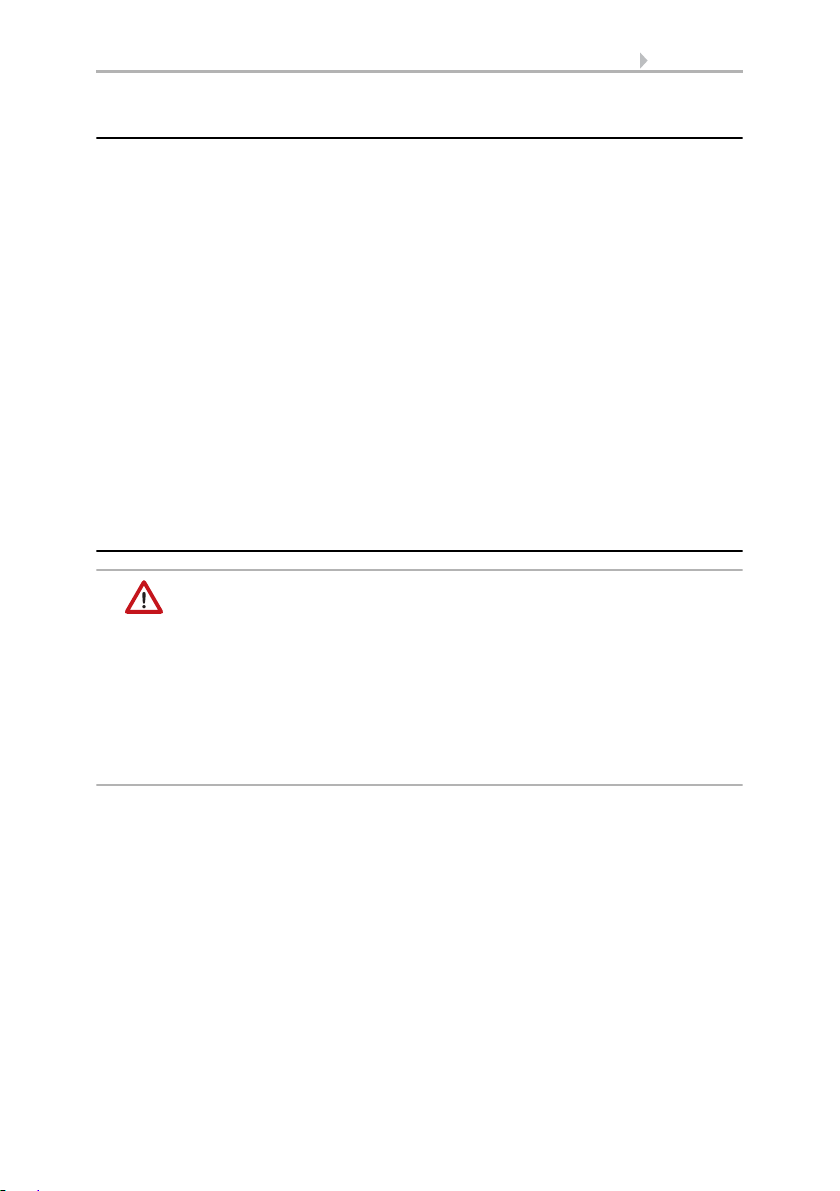
73 Installation
4.1.2. Notes on wireless equipment
When planning facilities with devices that communicate via radio, adequate radio reception must be guaranteed. The range of wireless control will be limited by legal regulation and structural circumstances. Avoid sources of interference and obstacles between receiver and transmitter, that could disturb the wireless communication. Those
would be for example:
• Walls and ceilings (especially concrete and solar protection glazing).
• Metal surfaces next to the wireless participants (e. g. aluminium construction
of a conservatory).
• Other wireless devices and powerful local transmitters (e.g. wireless
headphones), which transmit on the same frequency (868,2 MHz). Please
maintain a minimum distance of 30 cm between wireless transmitters for that
reason.
The transmission performance and reception sensitivity can be improved by means of
an external antenna. During installation, a conduit should be placed beneath the recessed housing, in which the external antenna can be mounted.
4.1.3. Safety notice for automatic and alarm
functions
WARNING!
Risk of injury due to automatically moved components!
The automatic control may cause parts of the system to travel
and pose a danger to humans.
• No persons may remain in the travelling range of parts
driven by an electric motor.
• Adhere to the relevant building regulations (see guideline for
power-operated windows, doors and gates BGR 232 et al).
• Always disconnect the system from the mains power before
maintenance or cleaning (e.g. switch off/remove fuse).
Precipitation warning for automatically controlled windows:
Some time can pass before falling rain is recognised by the sensors in the system, depending on the rain amount and outdoor temperature. Furthermore, a closure time
must be calculated for electrically-actuated windows or sliding roofs. Humiditysensitive items should therefore not be placed in an area where they might be damaged by
incoming precipitation. Please also bear in mind that in the event of a power failure and
rainfall, a window will not be automatically closed if no emergency generator is installed.
Running rails of shades icing up:
Note that the rails of shutters, awnings and blind which are externally mounted can ice
up. Operating the drive under such conditions can damage the shades and drives.
Control System WS1 Style / WS1000 Style • Version: 28.05.2018 • Technical changes and errors excepted.
Page 76

74 Installation
Power failure, maintenance works, etc. (restart of control)
If a power outage occurs, the control unit can no longer control the connected drives!
If the functional scope must be guaranteed even during a power cut, an emergency
power unit with a corresponding switch from network power to emergency operation
should be installed by the customer.
Settings saved in the control unit programme will be maintained even during a power
outage.
Note: After every re-start (e. g. return of voltage after mains failure or manual reset)
all drives and devices with active automatic reset are in automatic mode.
If cleaning or maintenance work is to be carried out in the conservatory/building, the
control unit should be de-energised and secure against restart by disconnection of the
customer-installed fuse. This ensures that the connected drives cannot start.
4.2. Installation of the P04i-GPS Weather Station
The P04i-GPS weather station for WS1 and WS1000 Color/Style measures temperature, wind speed and brightness. It recognises precipitation and receives the GPS signal for time and location (international time signal and position).
4.2.1. Installing the weather station
Installation location
Select an installation position on the building where the sensors can measure wind,
rain and sunshine without hindrance. No structural elements should be mounted
above the weather station from which water could continue to drop on the precipitation sensor even after it has stopped raining or snowing. The weather station should
not be shaded by structures or, for example, trees.
At least 60 cm of clearance must be left around the device. This facilitates correct wind
speed measurement without eddies. At the same time, this prevents spray (raindrops
hitting the device) or snow (snow penetration) from impairing the measurement. This
also prevents birds from biting it.
Please ensure that the extended awning does not cast shade on the unit, protects it
against the wind.
Temperature measurements can also be distorted by external influences such as
warming or cooling of the building structure on which the sensor is mounted (sunlight,
heating or cold water pipes).
Magnetic fields, transmitters and interference fields from electrical consumers (e.g. fluorescent lamps, neon signs, switch mode power supplies etc.) can block or interfere
with the reception of the GPS signal.
Control System WS1 Style / WS1000 Style • Version: 28.05.2018 • Technical changes and errors excepted.
Page 77

75 Installation
Fig. 1
There must be at least 60 cm clearance to other elements (structures, construction parts,
etc.) below, to the sides and in front of the
weather station.
60 cm
Fig. 2
The device must be attached to a vertical wall
(or a pole).
Wall
or
pole
90°
Fig. 3
The device must be mounted in the cross direction, i.e. in horizontal (transverse) direction.
Horizontal
Fig. 4
For installation in the northern hemisphere,
the device must be aligned to face south.
For installation in the southern hemisphere,
the device must be aligned to face north.
North
South
Control System WS1 Style / WS1000 Style • Version: 28.05.2018 • Technical changes and errors excepted.
Page 78

Device design
Fig. 5
1 GPS receiver in lid
2 Brightness measurement
3 Precipitation sensor in lid
4 Temperature measurement
5 Wind measurement
ATTENTION!
Sensitive wind sensor.
• Remove the protective transport sticker after installation.
• Do not touch the sensor on the wind measuring element (no. 5).
1
2
4
3
5
Fig. 6
Slacken both screws on the lid (top) and lower part (bottom) with a Phillips screwdriver.
76 Installation
ATTENTION!
Even a few drops of water can damage the device electronics.
• Do not open the device if water (e.g. rain) can get into it.
Preparation for installation
Control System WS1 Style / WS1000 Style • Version: 28.05.2018 • Technical changes and errors excepted.
Page 79

77 Installation
Fig. 7
Pull the lid and lower part completely apart.
This also releases the plug-in connection between the board in the lid and the socket in
the lower part.
Fig. 8
The device is installed with two screws. Break
off the two longitudinal holes in the lower
part of the housing.
Longitudinal holes
Fig. 9 a+b
a) If the power lead is to be hidden when in-
stalled, it must emerge from the wall in
the vicinity of the rear of the housing
(marked area).
Fitting the lower part with mounting
Now, first of all, assemble the lower part of the housing with the integrated mounting
for wall or pole installation.
Wall installation
Use fixing materials (dowels, screws) that are suitable for the base.
Control System WS1 Style / WS1000 Style • Version: 28.05.2018 • Technical changes and errors excepted.
Page 80

78 Installation
b) If the power lead is to be surface-mount-
ed, the cable guide is broken off. The lead
is then fed into the device at the underside of the housing.
Cable guide
Fig. 10
Feed the power lead through the rubber gasket.
Rubber
gasket
Fig. 11
Dimensions in mm. Variations are
possible for technical reasons
A/B2× longitudinal holes 8 mm ×
5.5 mm
C Position of the cable outlet (rub-
ber gasket) in the housing
AB
C
Drilling plan
ATTENTION! The printout of the data sheet does not have original size! A separate, dimensionally correct drilling plan is included ex works and this can be used as a template.
Control System WS1 Style / WS1000 Style • Version: 28.05.2018 • Technical changes and errors excepted.
Page 81
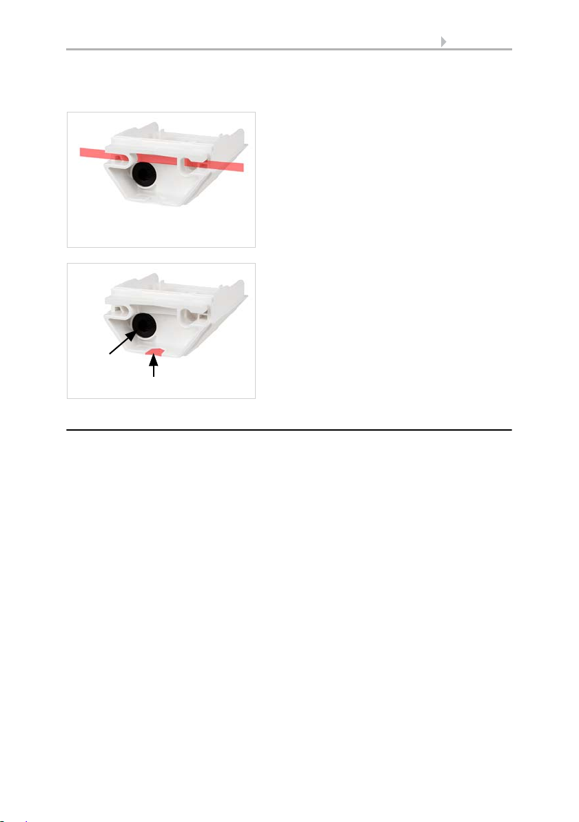
79 Installation
Fig. 12
Feed the mounting band through the eyelets
in the lower part of the housing.
Fig. 13
Break the cable guide off.
Feed the power lead through the rubber gasket.
Cable guide
Rubber
gasket
Pole installation
The device is installed on the pole with the enclosed stainless steel mounting band.
Connection
The connector is in the lower part of the housing.
The feed to the weather station must be a maximum of 100 m long. The connection is
made with off-the-shelf UV-resistant telephone cable (A-2Y(L)2Y 2x2x0.6 or A-2Y(L)2Y
2x2x0.8).
Control System WS1 Style / WS1000 Style • Version: 28.05.2018 • Technical changes and errors excepted.
Page 82

Closing the installation
Fig. 14
Connect
the controller/voltage (+24 V DC/GND) to the
terminals 1/2 P04i-GPS.
The terminal assignment is polarity-independent
12
Voltage
Controller
Fig. 15
Push the lid on the lower part. This also
makes the plug-in connection between the
board in the lid and the socket in the lower
part.
Fig. 16
Screw the lid (top) and lower part (bottom) together.
80 Installation
4.2.2. Notes on mounting and commissioning
Remove all existing protection labels after installation.
Control System WS1 Style / WS1000 Style • Version: 28.05.2018 • Technical changes and errors excepted.
Page 83

81 Installation
The correct wind value may only be supplied about 30 seconds after the supply voltage
has been connected.
4.2.3. Maintenance of the weather station
WARNING!
Risk of injury caused by components moved automatically!
The automatic control can start system components and place people in
danger (e.g. moving windows/awnings if a rain/wind alarm has been
triggered while cleaning).
• Always isolate the device from the mains for servicing and cleaning.
The device must regularly be checked for dirt twice a year and cleaned if necessary. In
case of severe dirt, the sensor may not work properly anymore.
ATTENTION
The device can be damaged if water penetrates the housing.
• Do not clean with high pressure cleaners or steam jets.
4.3. Installation of a WGTH-UP Indoor Sensor
The WS1 Style control system has an indoor sensor integrated into the central unit.
Further external sensors can additionally be installed. The WS1000 Style control system comes with an indoor sensor WGTH-UP included in the delivery.
The WGTH-UP Indoor Sensor transfers temperature and humidity to the control system via radio. Several separate WGTH-UP can be taught to one control system. The
teaching is described in the chapter “Learn wireless connections” (manual of the control system).
The WGTH-UP Indoor Sensor consists of the housing, the sensor PCB/base plate and a
frame. As an alternative to the supplied frame, a frame of the switch series used in the
building may be used. You will additionally require a junction box (Ø 60 mm, 42 mm
deep, not included in scope of delivery).
For power supply (7...30 V DC), e. g. 12 V DC can be tapped from the connection board
of the control unit (multifunctional input).
Control System WS1 Style / WS1000 Style • Version: 28.05.2018 • Technical changes and errors excepted.
Page 84

82 Installation
Fig. 17
1 Openings for air circulation
2 Opening programming LED
4 Opening programming button
for configurating the device
5 Openings for air circulation
(BOTTOM)
3
1
2
4
4.3.1. Installation of the indoor sensor
Installation location
The interior sensor is to be installed flush to the wall surface in a junction box (Ø 60
mm, 42 mm deep). The ideal installation hight is approx. 1.40 m above the ground.
When selecting an installation location, please ensure that the measurement results
are affected as little as possible by external influences. Possible sources of interference
include:
• Direct sunlight
• Drafts from windows and doors
• Draft from ducts which lead from other rooms to the junction box in which the
sensor is mounted.
• Waste heat from the control unit (when mounted above the display)
• Warming or cooling of the building structure on which the sensor is mounted,
e.g. due to sunlight, heating or cold water pipes
• Connection lines which lead from warmer or colder areas to the sensor
Temperature variations from such sources of interference must be corrected in the
control unit menu in order to ensure the specified accuracy of the sensor (see manual
chapter on Wireless connections > Status).
The indoor sensor must only be installed and used in dry,
interior spaces. Avoid condensation.
Layout
Control System WS1 Style / WS1000 Style • Version: 28.05.2018 • Technical changes and errors excepted.
Page 85

83 Installation
Fig. 18
1 Connection for power supply
7…30 V DC (+/-)
1
The programming button is situated behind the
right lower opening of the housing.
Use e. g. a paper-clip or a wire to press the button.
Rear view
Installation
First install the junction box. Seal the inlet tubes in order to prevent drafts.
Connect the power supply +/- to the connector terminals provided for this purpose on
the sensor board. Then screw the board/base plate onto the socket. Ensure that the
front side with the writing „TOP“ is directing out of the wall and that the arrows point
towards the top.
Position the frame of the switching programme. Insert the housing of the sensor firmly
onto the base plate using the catches, so that the housing and frame are fixed together.
4.3.2. Notes on mounting and commissioning
Never expose the device to water (e.g. rain) or dust. This can damage the electronics.
You must not exceed a relative humidity of 95%. Avoid condensation.
4.3.3. Establish radio connection with WGTH-UP
1. Bring the control unit into learning readiness mode (note chapter Learn wireless
connection in the manual).
2. Press the programming button at the WGTH-UP sensor
Control System WS1 Style / WS1000 Style • Version: 28.05.2018 • Technical changes and errors excepted.
Page 86

84 Installation
Conduit angled diagonally downwards
(for cable access from above or below)
Conduit angled vertically downwards
(only for cable access from above!)
concealed
concealed
45°
cable
cable
box
box
M16 conduit, 50 cm in length
M16 conduit,
50 cm in length
3. Pay attention to the report of the control unit (“Device successfully learnt”).
4.4. Installation of the control unit
The central unit is fixed in the wall. The magnetic wall mounting allows for a plane installation on the wall and an easy access to the SD card slot. The display unit may not
be used a a mobile device.
4.4.1. Installation of the control unit WS1000 Style
Preparing the installation location
The device must only be installed and used in dry, interior
spaces. Avoid condensation.
Cut-out dimensions for concealed box:
W = 248 mm +1 -0 | H = 165 mm +1 -0 | D = 84 mm
An external antenna can be connected in order to improve wireless communications.
During installation, a conduit 50 cm in length should be placed beneath the recessed housing, in which the external antenna can be mounted (antenna dimensions
approx. 565 x 8 x 5, L × W × H in mm):
Control System WS1 Style / WS1000 Style • Version: 28.05.2018 • Technical changes and errors excepted.
Page 87
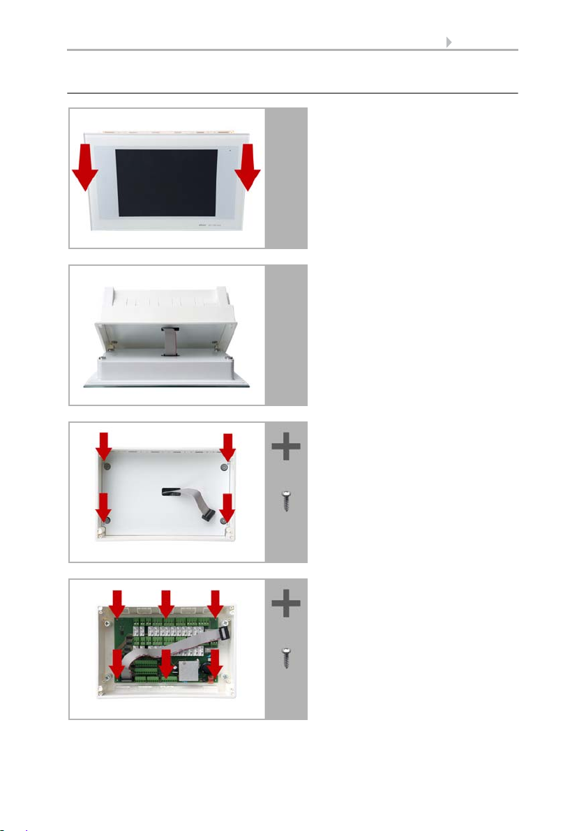
Preparing for installation
The display unit is held by magnets.
Remove the front part from the concealed box.
Caution: The display is connected
with a flat-ribbon cable to the circuit board in the concealed box.
Loosen the plug so that the display
unit can be removed.
Remove all parts of the transportation
lock/packing.
The security covering in the concealed
box is attached with four screws:
Loosen the screws and take off the security covering.
Remove the circuit board from the
concealed box to be installed a keep it
in a place where it is protected from
dirt. It may never be exposed to
dust or moisture!
85 Installation
Control System WS1 Style / WS1000 Style • Version: 28.05.2018 • Technical changes and errors excepted.
Page 88
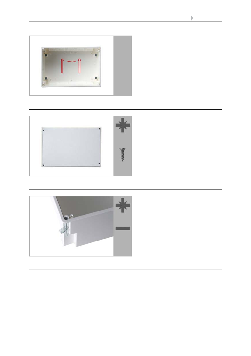
Wall-fitting
Place the concealed box in the wall so
that the arrows point upwards.
For fitting, screw the cover (board) on
to the concealed box with the enclosed screws.
Clamp the concealed box to the wall
with the four enclosed screws.
Upon delivery, the pouch containing
the assembly screws can be found in
the control unit’s concealed box.
oder
Cavity wall fitting
86 Installation
Assembling the control unit with concealed box
During electrical installation, please introduce all connection cables into the concealed
box through the lower or upper side wall. In the process, keep the individual connection wires short to prevent long reserve loops.
After connecting the cables screw the security covering onto the concealed box.
Control System WS1 Style / WS1000 Style • Version: 28.05.2018 • Technical changes and errors excepted.
Page 89

87 Installation
Adjust the screws of the magnetic
mounting with the enclosed template.
Each of the four screws must be adjusted individially in height.
When the edge of the template rests
on the wall surface (1), the template
must rest on the mounting screws as
well (2).
1
1
2
The security covering must be fixed before the control is put
into operation! It prevents contact with current-carrying parts
in the concealed box.
By adjusting the mounting screws, the display unit will rest flat on the wall later and be
held by the magnets safely.
Connect the flat ribbon cable to the display and place the display unit on the concealed
box. The magnets must be attracted by the mounting screws considerably and the display unit must rest tightly on the concealed box.
When connecting the display cable during operation, the display must not be touched
because of disturbances of the touch calibration function.
If the touch function doesn‘t work properly anymore, please restart the control unit,
e. g. by switching the power supply off/on. During the start-up procedure, the display
will be calibrated automatically. Otherwise use the function „Touch Calibration“ in the
menu.
System > WS1 / WS1000 Settings > Settings > Calibrate Touch
6.2.1. Calibrate touch
Control System WS1 Style / WS1000 Style • Version: 28.05.2018 • Technical changes and errors excepted.
Page 90

88 Installation
1 Multifunctional output 1
(potential-free)
2 Multifunctional output 2 (pot.-free)
3 Multifunctional output 3 (pot.-free)
4 Multifunctional output 4 (pot.-free)
5 Outer conductor L1
6 Outer conductor L1
7 Drive group 1
8 Drive group 2
9 Drive group 3
10 Drive group 4
11 Drive group 5
12 Drive group 6
13 Drive group 7
14 Drive group 8
15 Drive group 9
16 Drive group 10
17 Mains connection L/N/PE 230 V/50 Hz
18 Wall button 1 (terminals 1-3)
Wall button 2 (terminals 4-6)
Wall button 3 (terminals 7-9)
Wall button 4 (terminals 10-12)
19 Wall button 5 (terminals 1-3)
Wall button 6 (terminals 4-6)
Wall button 7 (terminals 7-9)
Wall button 8 (terminals 10-12),
20 Wall button 9 (terminals 1-3)
Wall button 10 (terminals 4-6),
21*Multifunctional input 1 (terminals 1-3)
Multifunctional input 2 (terminals 4-6)
22 Weather station (terminals 1-2)
23*Multifunctional input 3 (terminals 3-5)
Multifunctional input 4 (terminals 6-8)
24 Connector for flat-ribbon cable to front
board
25 Microfuse T6.3 A (Drive 1-5)
26 Microfuse T6.3 A (Drive 6-10)
27 Microfuse T630 mA
28 Slot KNX interface
* Supply voltage indoor sensor possible
via MF inputs
(No. 21, terminals 1(+), 2(-) | 4(+), 5(-)
and No. 23, term. 3(+), 4(-) | 6(+), 7(-)),
max. 400 mA altogether.
20
1
2
3
4
5
6
7
8
9
10
11
12
13 14
15
16
17
18
19
21
22
23
24
25
26
27
28
Structure of the connector board WS1000 Style
Control System WS1 Style / WS1000 Style • Version: 28.05.2018 • Technical changes and errors excepted.
Page 91
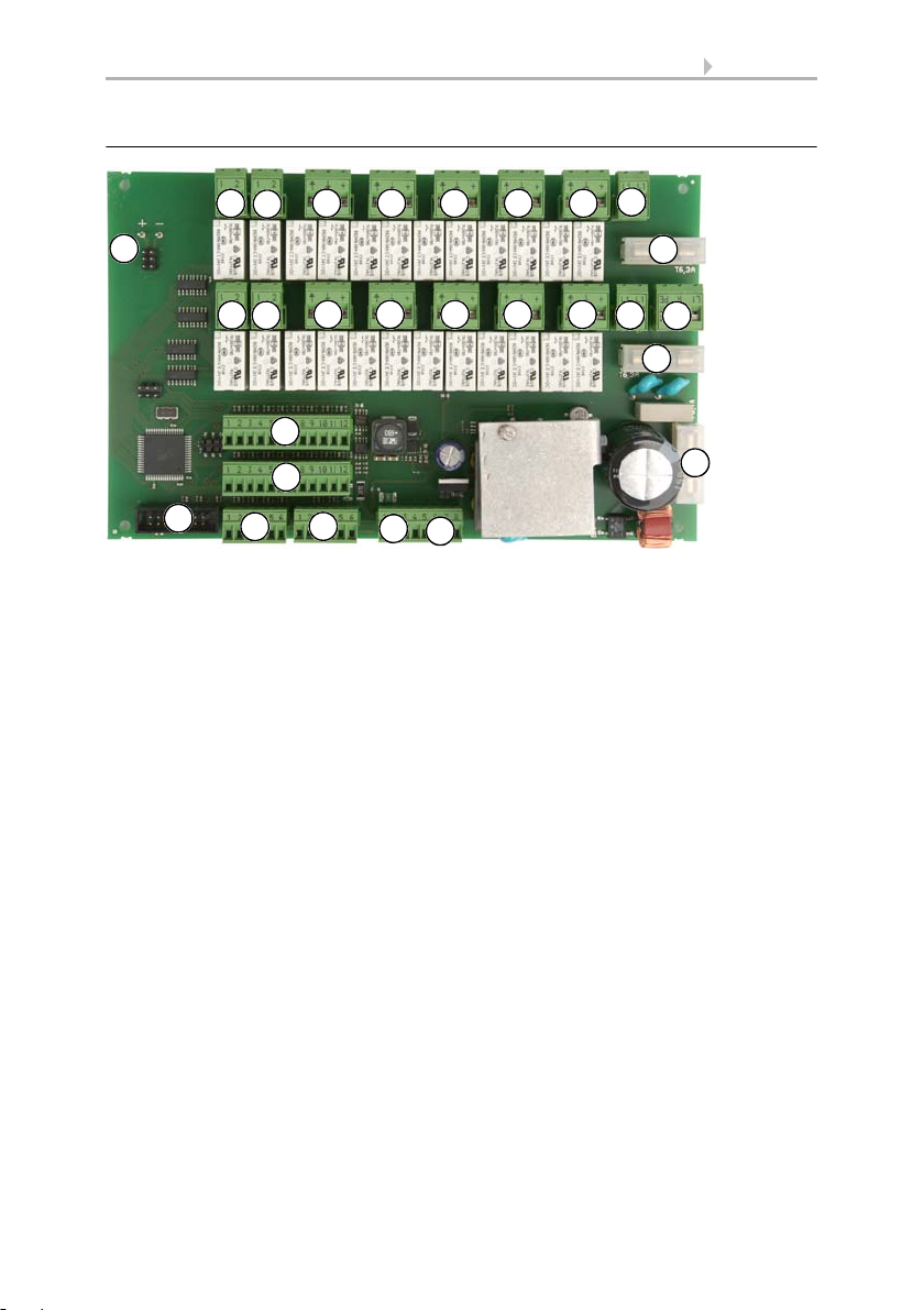
89 Installation
1 Multifunctional output 1
(potential-free)
2 Multifunctional output 2 (pot.-free)
3 Multifunctional output 3 (pot.-free)
4 Multifunctional output 4 (pot.-free)
5 Drive group 1
6 Drive group 2
7 Drive group 3
8 Drive group 4
9 Drive group 5
10 Drive group 6
11 Drive group 7
12 Drive group 8
13 Drive group 9
14 Drive group 10
15 Outer conductor L1
16 Outer conductor L1
17 Mains connection L/N/PE 230 V/50 Hz
18 Wall button 1 (terminals 1-3)
Wall button 2 (terminals 4-6)
Wall button 3 (terminals 7-9)
Wall button 4 (terminals 10-12)
19 Wall button 5 (terminals 1-3)
Wall button 6 (terminals 4-6)
Wall button 7 (terminals 7-9)
Wall button 8 (terminals 10-12),
20 Wall button 9 (terminals 1-3)
Wall button 10 (terminals 4-6),
21*Multifunctional input 1 (terminals 1-3)
Multifunctional input 2 (terminals 4-6)
22 Weather station (terminals 1-2)
23*Multifunctional input 3 (terminals 3-5)
Multifunctional input 4 (terminals 6-8)
24 Connector for flat-ribbon cable to front
board
25 Microfuse T6.3 A (Drive 1-5)
26 Microfuse T6.3 A (Drive 6-10)
27 Microfuse T630 mA
28 Slot KNX interface
* Supply voltage indoor sensor possible
via MF inputs
(No. 21, terminals 1(+), 2(-) | 4(+), 5(-)
and No. 23, term. 3(+), 4(-) | 6(+), 7(-)),
max. 400 mA altogether.
20
1
2
3
4
5 6 7 8 9
10 11 12 13 14
15
16
17
18
19
21
22
23
24
25
26
27
28
Structure of the connector board WS1000 Style-PF
Control System WS1 Style / WS1000 Style • Version: 28.05.2018 • Technical changes and errors excepted.
Page 92

90 Installation
Conduit angled diagonally downwards
(for cable access from above or below)
Conduit angled vertically downwards
(only for cable access from above!)
concealed
concealed
45°
cable
cable
box
box
M16 conduit, 50 cm in length
M16 conduit,
50 cm in length
4.4.2. Installation of the control unit WS1 Style
Preparing the installation location
The device must only be installed and used in dry, interior
spaces. Avoid condensation.
The device is to be installed flush to the wall surface. When selecting an installation
location, please ensure that the measurement results of the integrated temperature/
humidity sensor are affected as little as possible by external influences. Possible sources of interference include:
• Direct sunlight
• Drafts from windows and doors
• Draft from ducts which lead from other rooms to the concealed box
• Warming or cooling of the building structure on which the device is mounted,
e.g. due to sunlight, heating or cold water pipes
• Connection lines which lead from warmer or colder areas to the device
Cut-out dimensions for concealed box:
W = 166 mm +1 -0 | H = 116 mm +1 -0 | D = 80 mm
An external antenna can be connected in order to improve wireless communications.
During installation, a conduit 50 cm in length should be placed beneath the recessed housing, in which the external antenna can be mounted (antenna dimensions
approx. 565 x 8 x 5, L × W × H in mm):
Control System WS1 Style / WS1000 Style • Version: 28.05.2018 • Technical changes and errors excepted.
Page 93

Preparing for installation
The display unit is held by magnets.
Remove the front part from the concealed box.
Caution: The display is connected
with a flat-ribbon cable to the circuit board in the concealed box.
Loosen the plug so that the display
unit can be removed.
Remove all parts of the transportation
lock/packing.
The security covering in the concealed
box is attached with four screws:
Loosen the screws and take off the security covering.
Remove the circuit board from the
concealed box to be installed a keep it
in a place where it is protected from
dirt. It may never be exposed to
dust or moisture!
91 Installation
Control System WS1 Style / WS1000 Style • Version: 28.05.2018 • Technical changes and errors excepted.
Page 94
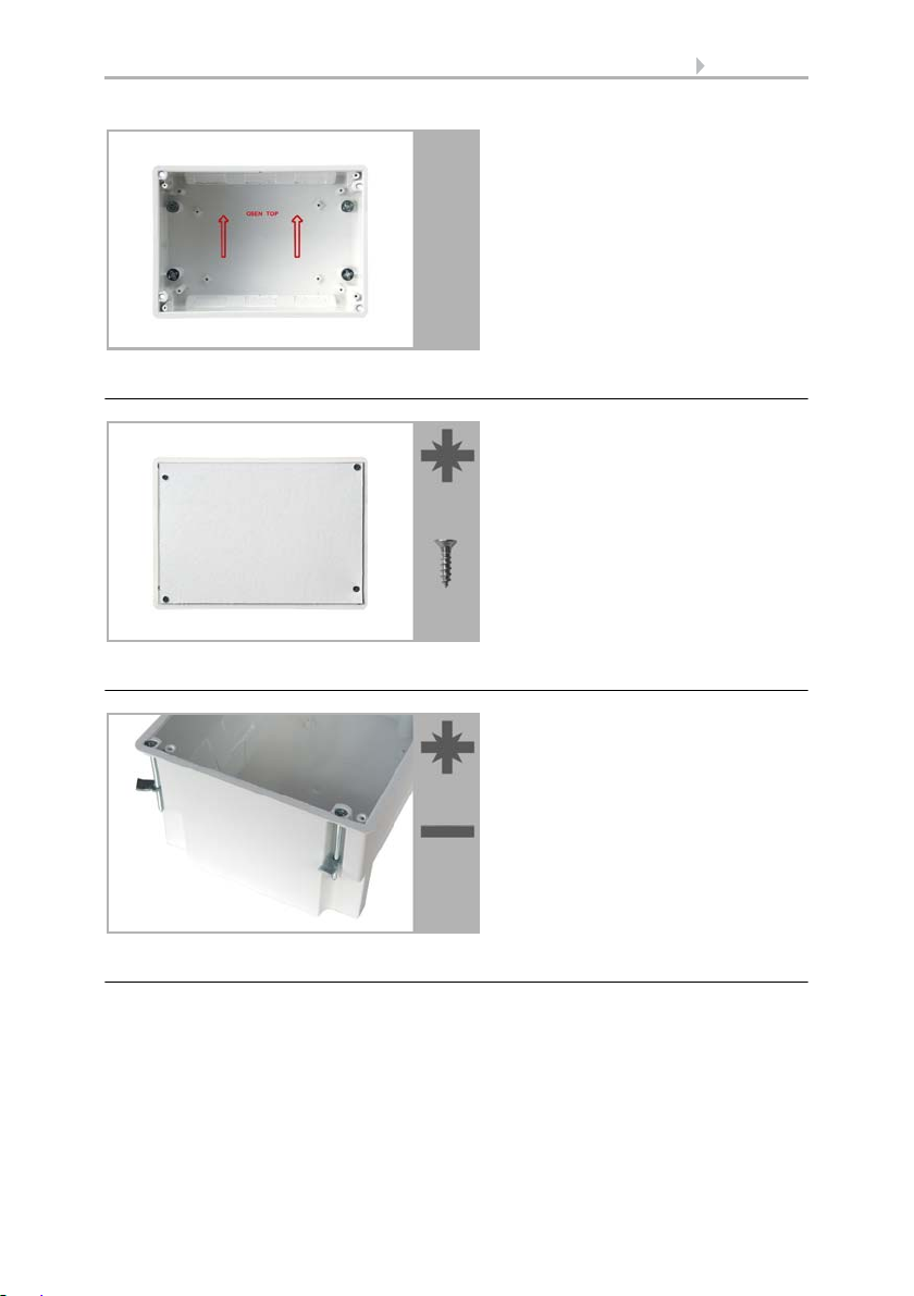
Wall-fitting
Place the concealed box in the wall so
that the arrows point upwards.
For fitting, screw the cover (board) on
to the concealed box with the enclosed screws.
Clamp the concealed box to the wall
with the four enclosed screws.
Upon delivery, the pouch containing
the assembly screws can be found in
the control unit’s concealed box.
or
Cavity wall fitting
92 Installation
Assembling the control unit with concealed box
During electrical installation, please introduce all connection cables into the concealed
box through the lower or upper side wall. In the process, keep the individual connection wires short to prevent long reserve loops.
After connecting the cables screw the security covering onto the concealed box.
Control System WS1 Style / WS1000 Style • Version: 28.05.2018 • Technical changes and errors excepted.
Page 95

93 Installation
Adjust the screws of the magnetic
mounting with the enclosed template.
Each of the four screws must be adjusted individially in height.
When the edge of the template rests
on the wall surface (1), the template
must rest on the mounting screws as
well (2).
1
1
2
The security covering must be fixed before the control is put
into operation! It prevents contact with current-carrying parts
in the concealed box.
By adjusting the mounting screws, the display unit will rest flat on the wall later and be
held by the magnets safely.
Connect the flat ribbon cable to the display and place the display unit on the concealed
box. The magnets must be attracted by the mounting screws considerably and the display unit must rest tightly on the concealed box.
When connecting the display cable during operation, the display must not be touched
because of disturbances of the touch calibration function.
If the touch function doesn‘t work properly anymore, please restart the control unit,
e. g. by switching the power supply off/on. During the start-up procedure, the display
will be calibrated automatically. Otherwise use the function „Touch Calibration“ in the
menu.
System > WS1 / WS1000 Settings > Settings > Calibrate Touch
6.2.1. Calibrate touch
Control System WS1 Style / WS1000 Style • Version: 28.05.2018 • Technical changes and errors excepted.
Page 96

94 Installation
1 Mains connection L/N/PE 230 V/50 Hz
2 Drive group 1
3 Drive group 2
4 Drive group 3
5 Drive group 4
6 Outer conductor L1
7 Multifunctional output 1
(potential-free)
8 MF output 2 (potential-free)
9 Wall button 1
(terminal 1: +12 V | 2: Up | 3: Down)
10 Wall button 2 (4: +12 V | 5: Up | 6: Down)
11 Wall button 3 (7: +12 V | 8: Up | 9: Down)
12 Wall button 4 (10:+12V|11:Up|12:Down)
13 Weather station (terminals 1-2)
14*Multifunctional input 1
(terminal 3: +12 V | 4: GND | 5: IN)
15*MF input 2 (6: +12 V | 7: GND | 8: IN)
16 Connector for flat-ribbon cable to front
board
17 Microfuse T6,3 A
* Supply voltage e. g. indoor sensor pos-
sible via MF inputs
(No. 14, terminal 3(+), 4(-) and
No. 15, terminal 6(+), 7(-)),
max. 50 mA altogether.
1
2
3
4
5
6
7
8
9
10
11
12
13
14
15
16
17
Structure of the connector board WS1 Style
Control System WS1 Style / WS1000 Style • Version: 28.05.2018 • Technical changes and errors excepted.
Page 97

95 Installation
1 Mains connection L/N/PE 230 V/50 Hz
2 Drive group 1
3 Drive group 2
4 Drive group 3
5 Drive group 4
6 Multifunctional output 1
(potential-free)
7 MF output 2 (potential-free)
8 Microfuse T630 mA
9 Wall button 1
(terminal 1: +12 V | 2: Up | 3: Down)
10 Wall button 2 (4: +12 V | 5: Up | 6: Down)
11 Wall button 3 (7: +12 V | 8: Up | 9: Down)
12 Wall button 4 (10:+12V|11:Up|12:Down)
13 Weather station (terminals 1-2)
14*Multifunctional input 1
(terminal 3: +12 V | 4: GND | 5: IN)
15*MF input 2 (6: +12 V | 7: GND | 8: IN)
16 Connector for flat-ribbon cable to front
board
* Supply voltage e. g. indoor sensor pos-
sible via MF inputs
(No. 14, terminal 3(+), 4(-) and
No. 15, terminal 6(+), 7(-)),
max. 50 mA altogether.
1
2
3
4
5
6
7
8
9
10
11
12
13
14
15
16
Structure of the connector board WS1 Style-PF
4.4.3. Connect drives and devices
Connect drive groups
Each drive that must be controlled individually requires a group of its own. It is not possible to individually control drives that are connected in a group. Only drives with the
same function (only windows, only awnings, only blinds, only shutters) can be brought
together in groups.
Shades with different orientations (east, south, west) should be placed in different
groups. Only in this way can the shades be controlled appropriately according to the
position of the sun.
Control System WS1 Style / WS1000 Style • Version: 28.05.2018 • Technical changes and errors excepted.
Page 98

96 Installation
Drives can be kept in secure position by using safety contacts (multifunctional inputs).
Take note that a safety contactis not capable of preventing collisions (e.g. if an awning
is installed over a window).
The device works with 230 V alternating voltage 50 Hz. The input power is dependent
on the number and power of the connected motors.
On the WS1/WS1000 Color version (for 230V drives), each drive outlet must have a
maximum 400-watt load. The total installed input must not however exceed approx.
1.5 KW. The output voltage is 230V AC.
On the WS1/WS1000 Color-PF version (with potential-free drive outputs), each relay
must have a maximum 400-watt load.
When motors are connected in parallel, take note of whether a group control relay is
prescribed by the manufacturer. Group control relays can be obtained from Elsner Elektronik or the motor manufacturer.
Various drives for blinds and awnings, in particular, can for the most part only be operated via a group control relay on an output channel.
If motors are connected in parallel which are unsuitable for this
purpose, both they and the control unit will be damaged.
Motors with a higher power input than 400 Watt are to be operated via a relay or control gate with its own power cable.
For D.C. drives we offer appropriate power supply units. In case of need we ask for details of the motor type, the manufacturer and – if available – the technical data.
Connect devices to the multifunctional outputs
Heatings, air-conditioners, lights, ventilation devices, roof gutter heatings, dimmers or
alarm devices (e.g. alarm equipment in combination with a motion detector in a multifunctional input) can be connected to the multifunctional outputs.
The multifunctional outputs have a potential-free make contact which can be loaded
with 230 V AC/2 A.
Connect devices to the multifunctional inputs
Devices with potential-free contacts can be connected to the multifunctional inputs.
These can be alarm-reporting devices, such as motion-detectors or smoke detectors
(with relay output) or another device with a potential-free contact, which is then crucial
for the alarm function.
A smoke alarm at the multi-functional input does not fulfil the
requirements for a smoke alarm system.
A heating or cooling plant operated independently of the control system can be connected to a multifunction input using its potential-free contact. Through the closed re-
Control System WS1 Style / WS1000 Style • Version: 28.05.2018 • Technical changes and errors excepted.
Page 99

97 Installation
lay, the device signals the control that it is currently heating or cooling and the control
activates the ventilation block.
A closed contact on the multifunction input can be used to test if a sliding door is
closed.
An impulse transmitter for the automatic reset can also be connected here, e.g. a sensor device or an alarm unit (impulse when activating).
4.4.4. Connection manual push buttons
Mechanical single or double push buttons can be connected to the push button inputs
and be assigned to the drives and devices in the menu.
ATTENTION
Bridging the UP button input doesn‘t guarantee that a drive stays in safe
position.
• Use a multifunctional input configuered as „safety contact“ to keep
drives in safe position.
6.1.5. Set Multifunctional Inputs
Connecting drives and devices wirelessly
Connecting drives and devices wirelessly is achieved by means of an Elsner wireless
modules (RF relay, RR-MSG). Elsner Elektronik ventilation devices can be learned into
the control system without any additional equipment. Please observe the installation
instructions relating to the wireless relays, motor control devices and ventilation devices.
6.1. Wireless connections
Control System WS1 Style / WS1000 Style • Version: 28.05.2018 • Technical changes and errors excepted.
Page 100

98 Installation
Control System WS1 Style / WS1000 Style • Version: 28.05.2018 • Technical changes and errors excepted.
 Loading...