

Page 1
EN
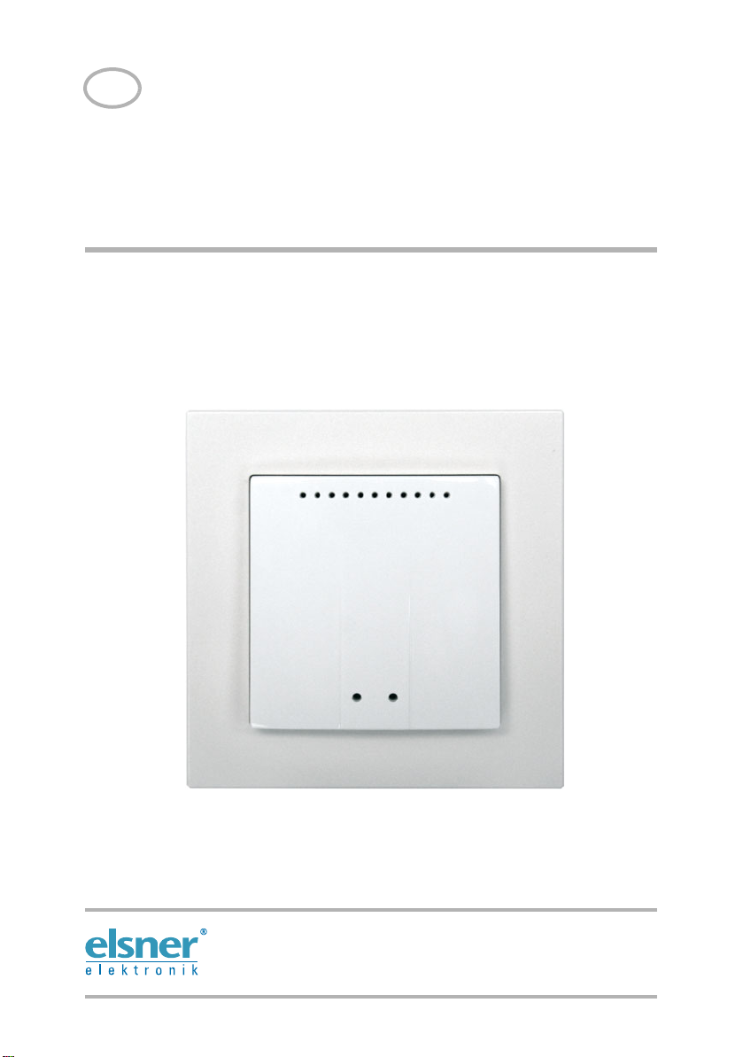
Indoor Sensor WGTH-UP
For WS1 Color/Style, (KNX) WS1000 Color/Style
Technical Specifications and Installat ion Instructions
Elsner Elektronik GmbH Control and Automation Engineering
Herdweg 7
D – 75391 Gechingen Phone +49 (0) 70 56 / 93 97-0 info@elsner-elektronik.de
Germany Fax +49 (0) 70 56 / 93 97-20 www.elsner-elektronik.de
Page 2

2 Installation of the indoor sensor
The WGTH-UP Indoor Sensor transfers temperature and humidity to the control system via radio. Several separate WGTH-UP can be taught to one control system. The
teaching is described in the chapter “Learn wireless connections” (manual of the control system).
The WGTH-UP Indoor Sensor consists of the housing, the sensor PCB/base plate and a
frame. As an alternative to the supplied frame, a frame of the switch series used in the
building may be used. You will additionally require a junction box (Ø 60 mm, 42 mm
deep, not included in scope of delivery).
For power supply (7...30 V DC), e. g. 12 V DC can be tapped from the connection board
of the control unit (multifunctional input).
1. Installation of the indoor sensor
1.1. Installation location
The interior sensor is to be installed flush to the wall surface in a junction box (Ø 60
mm, 42 mm deep). The ideal installation hight is approx. 1.40 m above the ground.
When selecting an installation location, please ensure that the measurement results
are affected as little as possible by external influences. Possible sources of interference
include:
• Direct sunlight
• Drafts from windows and doors
• Draft from ducts which lead from other rooms to the junction box in which the
sensor is mounted.
• Waste heat from the control unit (when mounted above the display)
• Warming or cooling of the building structure on which the sensor is mounted,
e.g. due to sunlight, heating or cold water pipes
• Connection lines which lead from warmer or colder areas to the sensor
Temperature variations from such sources of interference must be corrected in the
control unit menu in order to ensure the specified accuracy of the sensor (see manual
chapter on Wireless connections > Status).
The indoor sensor must only be installed and used in dry, interior spaces. Avoid condensation.
Indoor Sensor WGTH-UP • Status: 21.09.2012 • Subject to technical changes. Errors excepted.
Page 3

1.2. Layout
Abb. 1
1 Openings for air circulation
2 Opening programming LED
4 Opening programming button
for configurating the device
5 Openings for air circulation
(BOTTOM)
3
1
2
4
Abb. 2
1 Connection for power supply
7…30 V DC (+/-)
1
1.3. Rear view
3 Installation of the indoor sensor
1.4. Installation
First install the junction box. Seal the inlet tubes in order to prevent drafts.
Connect the power supply +/- to the connector terminals provided for this purpose on
the sensor board. Then screw the board/base plate onto the socket. Ensure that the
front side with the writing „TOP“ is directing out of the wall and that the arrows point
towards the top.
Position the frame of the switching programme. Insert the housing of the sensor firmly
onto the base plate using the catches, so that the housing and frame are fixed together.
Indoor Sensor WGTH-UP • Status: 21.09.2012 • Subject to technical changes. Errors excepted.
Page 4

4 Notes on mounting and commissioning
The programming button is situated behind the
right lower opening of the housing.
Use e. g. a paper-clip or a wire to press the button.
2. Notes on mounting and commissioning
Sensor must not be exposed to water (rain) or dust. This could result in the electronic
being damaged. A relative air humidity of 95% must not be exceeded. Avoid bedewing.
3. Establish radio connection with WGTH-UP
1. Bring the control unit into learning readiness mode (note chapter Learn wireless
connection in the manual).
2. Press the programming button at the WGTH-UP sensor
3. Pay attention to the report of the control unit (“Device successfully learnt”).
4. Notes on installation
Installation, inspection, commissioning and troubleshooting of
the device must only be carried out by a competent electrician.
Disconnect all lines to be assembled, and take safety precautions against accidental
switch-on.
The device is exclusively intended for appropriate use. With each inappropriate change
or non-observance of the instructions for use, any warranty or guarantee claim will be
void.
After unpacking the device, check immediately for any mechanical damages. In case of
transport damage, this must immediately notified to the supplier.
If damaged, the device must not be put into operation.
If an operation without risk may supposedly not be guaranteed, the device must be put
out of operation and be secured against accidental operation.
Indoor Sensor WGTH-UP • Status: 21.09.2012 • Subject to technical changes. Errors excepted.
Page 5

5 Technical specifications WGTH-UP
The device must only be operated as stationary system, i.e. only in a fitted state and
after completion of all installation and start-up works, and only in the environment intended for this purpose.
Elsner Elektronik does not assume any liability for changes in standards after publication of this instruction manual.
5. Technical specifications WGTH-UP
Housing Plastic (partially painted)
Colours • White, glossy (similar to RAL 9016 Traffic White)
Installation Flush-mounted (installed in wall within junction box
Protection rating IP 20
Dimensions Housing approx. 55 × 55 (W × H, mm)
Total weight approx. 50 g
Ambient temperature Operating -20…+70°C, Storage -55…+90°C
Ambient air humidity max. 95% rH, avoid condensation
Operating voltage 7…30 V DC
Current max. 35 mA
Data output Wireless
Wireless frequency 868.2 MHz
Protocol Proprietary protocol (Elsner RF)
Temperature measurement
range
Resolution (temperature) 0.1°C
Accuracy (temperature) ± 0.9°C at 25°C
Humidity measurement
range
Resolution (humidity) 0,3%
Accuracy (humidity) 0…20 % = ± 5% rH
Drift (humidity) ± 0.5% rH per year in normal atmosphere
• Matt aluminium
Ø 60 mm, 42 mm deep)
Installation depth approx. 15 mm
Backplate approx. 71 × 71 (W × H, mm)
-40…+100°C
0…100% rH
20…80 % = ± 3% rH
80…100 % = ± 5% rH
Indoor Sensor WGTH-UP • Status: 21.09.2012 • Subject to technical changes. Errors excepted.
 Loading...